WO2011122441A1 - ウレタン発泡成形体およびその製造方法 - Google Patents
ウレタン発泡成形体およびその製造方法 Download PDFInfo
- Publication number
- WO2011122441A1 WO2011122441A1 PCT/JP2011/057192 JP2011057192W WO2011122441A1 WO 2011122441 A1 WO2011122441 A1 WO 2011122441A1 JP 2011057192 W JP2011057192 W JP 2011057192W WO 2011122441 A1 WO2011122441 A1 WO 2011122441A1
- Authority
- WO
- WIPO (PCT)
- Prior art keywords
- particles
- urethane foam
- foam molded
- molded article
- thermally conductive
- Prior art date
- Legal status (The legal status is an assumption and is not a legal conclusion. Google has not performed a legal analysis and makes no representation as to the accuracy of the status listed.)
- Ceased
Links
Images


Classifications
-
- C—CHEMISTRY; METALLURGY
- C08—ORGANIC MACROMOLECULAR COMPOUNDS; THEIR PREPARATION OR CHEMICAL WORKING-UP; COMPOSITIONS BASED THEREON
- C08G—MACROMOLECULAR COMPOUNDS OBTAINED OTHERWISE THAN BY REACTIONS ONLY INVOLVING UNSATURATED CARBON-TO-CARBON BONDS
- C08G18/00—Polymeric products of isocyanates or isothiocyanates
- C08G18/06—Polymeric products of isocyanates or isothiocyanates with compounds having active hydrogen
- C08G18/70—Polymeric products of isocyanates or isothiocyanates with compounds having active hydrogen characterised by the isocyanates or isothiocyanates used
- C08G18/72—Polyisocyanates or polyisothiocyanates
- C08G18/74—Polyisocyanates or polyisothiocyanates cyclic
- C08G18/76—Polyisocyanates or polyisothiocyanates cyclic aromatic
- C08G18/7657—Polyisocyanates or polyisothiocyanates cyclic aromatic containing two or more aromatic rings
- C08G18/7664—Polyisocyanates or polyisothiocyanates cyclic aromatic containing two or more aromatic rings containing alkylene polyphenyl groups
- C08G18/7671—Polyisocyanates or polyisothiocyanates cyclic aromatic containing two or more aromatic rings containing alkylene polyphenyl groups containing only one alkylene bisphenyl group
-
- C—CHEMISTRY; METALLURGY
- C08—ORGANIC MACROMOLECULAR COMPOUNDS; THEIR PREPARATION OR CHEMICAL WORKING-UP; COMPOSITIONS BASED THEREON
- C08G—MACROMOLECULAR COMPOUNDS OBTAINED OTHERWISE THAN BY REACTIONS ONLY INVOLVING UNSATURATED CARBON-TO-CARBON BONDS
- C08G18/00—Polymeric products of isocyanates or isothiocyanates
- C08G18/06—Polymeric products of isocyanates or isothiocyanates with compounds having active hydrogen
- C08G18/28—Polymeric products of isocyanates or isothiocyanates with compounds having active hydrogen characterised by the compounds used containing active hydrogen
- C08G18/30—Low-molecular-weight compounds
- C08G18/32—Polyhydroxy compounds; Polyamines; Hydroxyamines
- C08G18/3203—Polyhydroxy compounds
- C08G18/3206—Polyhydroxy compounds aliphatic
-
- C—CHEMISTRY; METALLURGY
- C08—ORGANIC MACROMOLECULAR COMPOUNDS; THEIR PREPARATION OR CHEMICAL WORKING-UP; COMPOSITIONS BASED THEREON
- C08G—MACROMOLECULAR COMPOUNDS OBTAINED OTHERWISE THAN BY REACTIONS ONLY INVOLVING UNSATURATED CARBON-TO-CARBON BONDS
- C08G18/00—Polymeric products of isocyanates or isothiocyanates
- C08G18/06—Polymeric products of isocyanates or isothiocyanates with compounds having active hydrogen
- C08G18/28—Polymeric products of isocyanates or isothiocyanates with compounds having active hydrogen characterised by the compounds used containing active hydrogen
- C08G18/40—High-molecular-weight compounds
- C08G18/48—Polyethers
- C08G18/4829—Polyethers containing at least three hydroxy groups
-
- C—CHEMISTRY; METALLURGY
- C08—ORGANIC MACROMOLECULAR COMPOUNDS; THEIR PREPARATION OR CHEMICAL WORKING-UP; COMPOSITIONS BASED THEREON
- C08G—MACROMOLECULAR COMPOUNDS OBTAINED OTHERWISE THAN BY REACTIONS ONLY INVOLVING UNSATURATED CARBON-TO-CARBON BONDS
- C08G18/00—Polymeric products of isocyanates or isothiocyanates
- C08G18/06—Polymeric products of isocyanates or isothiocyanates with compounds having active hydrogen
- C08G18/28—Polymeric products of isocyanates or isothiocyanates with compounds having active hydrogen characterised by the compounds used containing active hydrogen
- C08G18/65—Low-molecular-weight compounds having active hydrogen with high-molecular-weight compounds having active hydrogen
- C08G18/66—Compounds of groups C08G18/42, C08G18/48, or C08G18/52
- C08G18/6666—Compounds of group C08G18/48 or C08G18/52
- C08G18/667—Compounds of group C08G18/48 or C08G18/52 with compounds of group C08G18/32 or polyamines of C08G18/38
- C08G18/6674—Compounds of group C08G18/48 or C08G18/52 with compounds of group C08G18/32 or polyamines of C08G18/38 with compounds of group C08G18/3203
-
- C—CHEMISTRY; METALLURGY
- C08—ORGANIC MACROMOLECULAR COMPOUNDS; THEIR PREPARATION OR CHEMICAL WORKING-UP; COMPOSITIONS BASED THEREON
- C08G—MACROMOLECULAR COMPOUNDS OBTAINED OTHERWISE THAN BY REACTIONS ONLY INVOLVING UNSATURATED CARBON-TO-CARBON BONDS
- C08G2110/00—Foam properties
- C08G2110/0083—Foam properties prepared using water as the sole blowing agent
Definitions
- the present invention relates to a urethane foam molded article used as, for example, a sound absorbing material or a vibration absorbing material, and a manufacturing method thereof.
- Urethane foam moldings are used in various fields such as automobiles as sound absorbing materials, vibration absorbing materials and the like (see, for example, Patent Document 1).
- the urethane foam molded article has a large number of cells (bubbles) inside. For this reason, the thermal conductivity of the urethane foam molding is small. Therefore, when it arrange
- Patent Documents 2 and 3 disclose urethane foam molded articles having oriented magnetic particles.
- a filler having a large thermal conductivity can be contained in the urethane foam molded article.
- the filler having a high thermal conductivity include carbon fiber.
- simply blending carbon fibers makes it difficult to connect them to each other to form a heat transfer path.
- foam molding may be affected, and physical properties such as sound absorption characteristics may be reduced.
- the problem that the mass of a urethane foam molding increases and cost also arises.
- Carbon fiber is a non-magnetic material. Therefore, even if foam molding is performed in a magnetic field as magnetic particles are oriented, carbon fibers cannot be oriented.
- This invention is made in view of such a situation, and makes it a subject to provide a urethane foam molded object with high heat conductivity, without changing a physical property as much as possible. It is another object of the present invention to provide a manufacturing method thereof.
- the urethane foam molded article of the present invention has a base material made of polyurethane foam and a thermally conductive filler blended in the base material and aligned in an aligned manner.
- the thermally conductive filler is characterized by comprising composite particles having thermally conductive particles made of a non-magnetic material and magnetic particles attached to the surface of the thermally conductive particles.
- the thermally conductive filler is composed of composite particles having thermally conductive particles and magnetic particles.
- the thermally conductive particles forming the core of the composite particles have a large thermal conductivity, but are made of a nonmagnetic material.
- magnetic particles are attached to the surface of the heat conductive particles. For this reason, when a magnetic field is applied during foam molding, the magnetic particles tend to be oriented along the lines of magnetic force. Thereby, the composite particles are oriented along the magnetic field lines. That is, the thermally conductive particles can be oriented using the magnetic field orientation of the magnetic particles attached to the surface.
- the composite particles are arranged in the base material in a state of being connected to each other.
- a heat transfer path is formed in the substrate. That is, the heat applied to one end of the urethane foam molded article of the present invention is transmitted to the other end in the orientation direction via the heat conductive filler, and is quickly released from the other end.
- the urethane foam molded article of the present invention is excellent in thermal conductivity. Therefore, according to the urethane foam molded article of the present invention, it is possible to effectively suppress an increase in the temperature of the sound absorbing object serving as a heat source.
- the magnetic particles are oriented in a resin or rubber without foaming, it is difficult to achieve a desired orientation state due to thermal contraction of the resin or rubber during molding and thermal fluctuation of the resin or rubber during thermosetting.
- the liquid foamed urethane resin raw material grows by foaming during the production process. Accordingly, when the thermally conductive filler is oriented in the direction in which the foamed urethane resin material grows, the movement of the thermally conductive filler is promoted along with the growth of the foamed urethane resin material, and a desired orientation state is easily realized.
- the heat conductive filler is oriented, the influence on the skeleton formation of the polyurethane foam is small. That is, in the urethane foam molded article, the cell structure is difficult to change. Furthermore, compared with the case where the magnetic particle with small heat conductivity is orientated, thermal conductivity can be improved with a smaller amount of filler. Accordingly, physical properties such as tensile strength, elongation, and sound absorption characteristics of the urethane foam molded article are hardly changed. Further, by reducing the blending amount of the filler, it is possible to reduce the weight of the urethane foam molded body and reduce the cost.
- the heat conductive filler in the substrate may be arranged in a predetermined direction with a certain regularity. For example, it may be arranged linearly between one end and the other end of the urethane foam molded body (not necessarily the end opposite to the one end by 180 °) or may be arranged in a curved shape. . Moreover, you may arrange
- the method for producing a urethane foam molded article according to the present invention is a method for producing a urethane foam molded article having the configuration of (1) above, in which a foamed urethane resin raw material and the thermally conductive filler are mixed.
- a urethane foam molded article is produced by orienting the thermally conductive filler in a magnetic field.
- foam molding is performed in a magnetic field in which the magnetic flux density in the cavity is substantially uniform.
- uneven distribution of the heat conductive filler due to the difference in magnetic flux density can be suppressed, and a desired orientation state can be obtained.
- the heat conductive filler can be oriented in a substantially uniformly dispersed state. Therefore, according to the production method of the present invention, the urethane foam molded article of the present invention having high thermal conductivity can be easily produced even if the blending amount of the thermally conductive filler is relatively small.
- the present invention it is possible to provide a urethane foam molded article having improved thermal conductivity without impairing the original physical properties of the urethane foam molded article. Moreover, the simple manufacturing method can be provided.
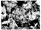
- Example 2 It is a SEM photograph of the composite particles of Example 1 (magnification 200 times). It is a SEM photograph of the composite particles of Example 2 (magnification 200 times).
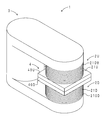
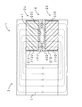
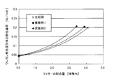
- an Example it is a perspective view of the 1st magnetic induction foam molding apparatus used for manufacture of a urethane foam molding. It is sectional drawing of the same apparatus. It is a graph which shows the measurement result of the heat conductivity of the urethane foam molding of Examples 1, 2 and a comparative example.
- it is a perspective view of the 2nd magnetic induction foam molding apparatus used for manufacture of a urethane foam molding. It is sectional drawing of the same apparatus.
- First magnetic induction foam molding apparatus 2U, 2D Electromagnet part 20U, 20D: Core part 21U, 21D: Coil part 210U, 210D: Conductor 3: Yoke part 4: Foaming mold 40U: Upper mold 40D: Lower mold 41: Cavity 5: Second magnetic induction foam molding apparatus 6: Stand 61: Bracket 7: Electromagnet part 70D, 70U: Yoke part 71L, 71R: Coil part 72D, 72U: Pole piece 710L, 710R: Core part 711L, 711R: Conductor 8 : Foaming mold 80U: Upper mold 80D: Lower mold 81: Cavity L: Magnetic field line
- urethane foam molded article and the production method thereof according to the present invention will be described.
- the urethane foam molded article and the method for producing the same according to the present invention are not limited to the following embodiments, and various modifications and improvements that can be made by those skilled in the art without departing from the gist of the present invention. It can implement with the form of.
- the urethane foam molded article of the present invention has a base material made of polyurethane foam, and a thermally conductive filler that is blended in the base material and aligned and connected to each other.
- Polyurethane foam is manufactured from foamed urethane resin raw materials such as a polyisocyanate component and a polyol component. Details will be described in the method for producing a urethane foam molded article of the present invention described later.
- the thermally conductive filler is composed of composite particles having thermally conductive particles made of a non-magnetic material and magnetic particles attached to the surface of the thermally conductive particles.
- the heat conductive particles may be non-magnetic and have high thermal conductivity.
- diamagnetic materials and paramagnetic materials other than ferromagnetic materials and antiferromagnetic materials are referred to as nonmagnetic materials.
- the thermal conductivity of the thermally conductive particles is desirably 200 W / m ⁇ K or more.
- a material of the heat conductive particles for example, a carbon material such as graphite or carbon fiber is suitable. Also, aluminum, gold, silver, copper, and alloys based on these may be used.
- the heat conductive particles one kind of particles may be used or two or more kinds of particles may be used in combination.
- the shape of the heat conductive particle is not particularly limited as long as it can be combined with the magnetic particle.
- various shapes such as a flaky shape, a fibrous shape, a columnar shape, a spherical shape, an elliptical sphere shape, and an oval sphere shape (a shape in which a pair of opposing hemispheres are connected by a cylinder) can be employed.
- the thermally conductive particles have a shape other than a sphere, the contact area between the composite particles (thermally conductive fillers) increases. As a result, a heat transfer path is easily secured and the amount of heat transferred is increased.
- the shape of metal particles such as aluminum, gold, and copper is spherical. Therefore, if the aspect ratio is increased, the processing cost is increased. On the other hand, graphite can be obtained at a relatively low cost even in a shape with a large aspect ratio. From such a viewpoint, graphite is suitable as a material for the thermally conductive particles.
- graphite examples include natural graphite such as scaly graphite, scaly graphite, and earthy graphite, and artificial graphite. Artificial graphite is not easily scaled. For this reason, natural graphite is suitable because it is scaly and has a high effect of improving thermal conductivity.
- expanded graphite in which a substance that generates gas by heating is inserted between scaly graphite layers may be used. Expanded graphite is used as a flame retardant, as disclosed in Patent Documents 4 and 5, for example. When heat is applied to expanded graphite, the generated gas expands the layers and forms a stable layer against heat and chemicals. The formed layer becomes a heat-insulating layer and prevents heat transfer, thereby providing a flame retardant effect.
- a urethane foam molded article to which flame retardancy is imparted has a dropping action that suppresses fire spread by dropping a fire type even when exposed to flame.
- the dropping effect is impaired, and the self-digestibility of the urethane foam molded article may be reduced.
- the composite particles thermally conductive filler
- the thermally conductive particles are made of expanded graphite, the expanded graphite reaches the expansion start temperature early. Thereby, the flame-retardant effect by expanded graphite is exhibited rapidly. Therefore, by using expanded graphite as the heat conductive particles, it is possible to suppress a decrease in self-digestibility of the urethane foam molded article and maintain flame retardancy.
- a suitable one may be selected from known expanded graphite powder in consideration of the expansion start temperature, the expansion rate, and the like.
- the expansion start temperature of expanded graphite must be higher than the exothermic temperature at the time of molding a urethane foam molded article.
- expanded graphite having an expansion start temperature of 150 ° C. or higher is suitable.
- the flame retardancy of the urethane foam molded article can be improved.
- the content of expanded graphite is desirably 5% by mass or more when the mass of the entire urethane foam molded article is 100% by mass.
- the composite particles include both composite particles in which magnetic particles are attached to the surface of expanded graphite particles, and composite particles in which magnetic particles are attached to the surface of particles made of a nonmagnetic material other than expanded graphite.
- Embodiments are desirable.
- the blending ratio of each composite particle may be appropriately determined in consideration of flame retardancy, moldability, and the like.
- the size of the heat conductive particles may be determined in consideration of dispersibility, an apparatus used for foam molding, and the like. For example, it is desirable that the average particle diameter of the heat conductive particles be 500 ⁇ m or less. 250 ⁇ m or less is more preferable. In the present specification, the maximum length of the thermally conductive particles is adopted as the particle diameter. In addition, as will be described in detail later, when the collision stirring method is employed in the method for producing a urethane foam molded article, it is desirable to use a thermally conductive particle having a maximum length of 500 ⁇ m or less.
- the magnetic particles only have to have excellent magnetization characteristics.
- iron, nickel, cobalt, gadolinium, stainless steel, magnetite, maghemite, manganese zinc ferrite, barium ferrite, strontium ferrite and other ferromagnetic materials, MnO, Cr Antiferromagnetic materials such as 2 O 3 , FeCl 2 , and MnAs, and alloys particles using these are preferable.
- iron, nickel, cobalt, and powders of these iron-based alloys are preferable from the viewpoint of easy availability as fine particles and high saturation magnetization.
- the magnetic particles are attached to the surface of the thermally conductive particles and play a role of orienting the composite particles (thermally conductive filler).
- the magnetic particles may be attached to only a part of the surface of the heat conductive particles, or may be attached so as to cover the entire surface.
- the size of the magnetic particles may be appropriately determined in consideration of the size of the thermally conductive particles, the orientation of the composite particles, the thermal conductivity between the composite particles, and the like. For example, when the size of the magnetic particles is reduced, the saturation magnetization of the magnetic particles tends to decrease. Therefore, in order to orient the composite particles with a smaller amount of magnetic particles, the average particle size of the magnetic particles needs to be 100 nm or more. It is more preferable that the thickness is 1 ⁇ m or more, further 5 ⁇ m or more. In the present specification, the maximum length of the magnetic particles is adopted as the particle diameter.
- the shape of the magnetic particles is not particularly limited.
- the shape of the magnetic particles is flat, the distance between adjacent heat conductive particles is shortened. Thereby, the thermal conductivity between adjacent composite particles is improved. As a result, the thermal conductivity of the urethane foam molding is improved.
- the shape of the magnetic particles is flat, the magnetic particles and the heat conductive particles are in contact with each other on the surface. That is, the contact area between the two becomes large. Thereby, the adhesive force of a magnetic particle and a heat conductive particle improves. Therefore, the magnetic particles are difficult to peel off.
- the thermal conductivity between the magnetic particles and the thermally conductive particles is also improved. For these reasons, it is desirable to employ flaky particles as the magnetic particles.
- the volume ratio of graphite to magnetic particles in the composite particles is 7: 3 to 5: considering the orientation of the composite particles and the effect of improving the heat conductivity. 5 is desirable.
- the volume ratio of the magnetic particles is less than 30%, the magnetism necessary for orientation may be insufficient.
- the volume ratio of graphite is less than 50%, the effect of improving thermal conductivity is reduced.
- the composite particles can be produced by a wet electrostatic adsorption method, a dry pulverization and mixing method, a stirring granulation method, a mechanochemical method, or the like.
- a stirring granulation method a raw material containing a powder of heat conductive particles, a powder of magnetic particles, and a binder for bonding them together is granulated by stirring at high speed.
- the heat conductive particles and the magnetic particles can be softly bonded with the binder. For this reason, even when the thermally conductive particles have a shape with a high thermal conductivity (a shape with a large aspect ratio), they can be combined with the magnetic particles without breaking the shape.
- the type of binder may be appropriately selected in consideration of the types of heat conductive particles and magnetic particles, the influence on foam molding, and the like. During the production of composite particles, frictional heat is generated by high-speed stirring. For this reason, as a binder, a non-volatile thing is desirable. In view of the environment, a water-based binder is preferable.
- the aqueous binder include methyl cellulose, carboxymethyl cellulose, hydroxypropyl methyl cellulose, and polyvinyl alcohol.
- Insulation properties may be required for the urethane foam molded body of the present invention, such as for heat dissipation of electronic parts.
- the composite particles have electrical conductivity, it is desirable to use composite particles whose surfaces are covered with an insulating layer as the thermally conductive filler.
- the composite particles can be provided with insulating properties without impairing the magnetic field orientation.
- Examples of the material for the insulating layer include epoxy resin and phenol resin.
- Examples of the method for forming the insulating layer include a method of immersing the composite particles in a resin solution in which a resin is dissolved in a solvent such as a solvent and water, and a method of spraying the resin solution onto the composite particles.
- the thickness of the insulating layer is desirably 1 ⁇ m or less from the viewpoint of imparting insulation without impairing thermal conductivity.
- the binding force between the magnetic particles and the heat conductive particles increases. Therefore, separation of the thermally conductive particles and the magnetic particles is suppressed in a mechanical mixing process, a raw material mixing process by high pressure injection, a high pressure foaming process, and the like.
- the insulating layer is made of a resin having a hydroxyl group such as an epoxy resin or a phenol resin, the adhesion between the polyurethane foam as the base material and the composite particles is improved. Therefore, the composite particles (thermally conductive filler) are not easily dropped from the base material, and a good orientation state can be maintained. Moreover, the effect of improving physical properties such as tensile strength and elongation of the urethane foam molded article can be expected by improving the adhesion between the base material and the composite particles.
- the blending amount of the heat conductive filler is 10 volumes when the volume of the urethane foam molded article is 100% by volume. % Or less is desirable. It is more suitable when it is 5 volume% or less.
- the blending amount of the thermal conductive filler is preferably 0.5% by volume or more. It is more suitable when it is 1 volume% or more.
- the manufacturing method of the urethane foam molding of this invention has a raw material mixing process and a foam molding process. Hereinafter, each step will be described.
- Raw material mixing step This step is a step of mixing a foamed urethane resin raw material and a thermally conductive filler to obtain a mixed raw material.
- the foamed urethane resin raw material may be prepared from already known raw materials such as polyol and polyisocyanate.
- Polyols include polyhydric hydroxy compounds, polyether polyols, polyester polyols, polymer polyols, polyether polyamines, polyester polyamines, alkylene polyols, urea-dispersed polyols, melamine-modified polyols, polycarbonate polyols, acrylics What is necessary is just to select suitably from polyols, polybutadiene polyols, phenol modified polyols, etc.
- polyisocyanate examples include tolylene diisocyanate, phenylene diisocyanate, xylylene diisocyanate, diphenylmethane diisocyanate, triphenylmethane triisocyanate, polymethylene polyphenyl isocyanate, naphthalene diisocyanate, and derivatives thereof (for example, by reaction with polyols). What is necessary is just to select suitably from prepolymers obtained, modified polyisocyanate, etc.).
- a catalyst In addition to the foamed urethane resin raw material, a catalyst, a foaming agent, a foam stabilizer, a plasticizer, a crosslinking agent, a flame retardant, an antistatic agent, a viscosity reducing agent, a stabilizer, a filler, a colorant, and the like may be appropriately blended.
- the catalyst include amine-based catalysts such as tetraethylenediamine, triethylenediamine, and dimethylethanolamine, and organometallic catalysts such as tin laurate and tin octoate.
- water is suitable as the foaming agent.
- methylene chloride In addition to water, methylene chloride, chlorofluorocarbons, CO 2 gas, and the like can be given.
- a silicone type foam stabilizer is suitable as the foam stabilizer, and triethanolamine, diethanolamine and the like are suitable as the crosslinking agent.
- the constitution and blending amount of the heat conductive filler are as described in the description of the urethane foam molded body of the present invention. Therefore, the description is omitted here.
- the mixed raw material can be manufactured, for example, by mechanically stirring the foamed urethane resin raw material and the heat conductive filler using a propeller or the like.
- at least one of the two components of the foamed urethane resin material (polyol material, polyisocyanate material) is added with a heat conductive filler to prepare two types of materials, and then the two materials are mixed and manufactured. Also good.
- this step is performed by preparing a polyol raw material containing a polyol, a catalyst, and a foaming agent and a polyisocyanate raw material containing a polyisocyanate as a foamed urethane resin raw material, and the polyol raw material and the polyisocyanate raw material.
- a raw material preparation step in which a heat conductive filler is blended in at least one of the above, a polyol raw material and a polyisocyanate raw material, respectively, and fed to a mixing head, and both raw materials are mixed in the mixing head to be a mixed raw material And a mixing step.
- the collision stirring method it is possible to employ a collision stirring method in which a polyol raw material and a polyisocyanate raw material are each injected and collided at a high pressure in the mixing head. According to the collision stirring method, continuous production becomes possible. Therefore, the collision stirring method is suitable for mass production. Further, according to the collision stirring method, the container cleaning step which is necessary every time of mixing is not required and the yield is improved as compared with the mechanical stirring method. Therefore, manufacturing cost can be reduced.
- a polyol raw material and a polyisocyanate raw material preliminarily blended with a heat conductive filler are each injected and collided at high pressure from an injection hole provided in a mixing head of a high pressure foaming apparatus. If the size of the thermally conductive filler is larger than the hole diameter of the injection hole, the injection hole is likely to be damaged due to contact with the heat conductive filler. Thereby, there exists a possibility that durability of a mixing head may fall. Moreover, the larger the size of the heat conductive filler, the more easily the heat conductive filler settles in the polyol raw material. For this reason, uniform mixing is difficult.
- the maximum length of the heat conductive filler is smaller than the diameter of the injection hole into which the polyol raw material and the polyisocyanate raw material are injected. By doing so, it is possible to reduce the load on the mixing head and extend the life of the high-pressure foaming apparatus. Moreover, sedimentation of the heat conductive filler is suppressed, and an increase in viscosity in the polyol raw material can be reduced.
- the maximum length of the heat conductive filler is desirably 500 ⁇ m or less.
- the magnetic field may be formed in the direction in which the thermally conductive filler is oriented.
- the thermally conductive filler is oriented linearly, it is desirable that the magnetic lines of force in the foam-type cavity are substantially parallel from one end of the cavity to the other end.
- magnets may be disposed near both surfaces of one end and the other end of the foaming mold so as to sandwich the foaming mold.
- a permanent magnet or an electromagnet may be used as the magnet.
- an electromagnet When an electromagnet is used, magnetic field formation can be switched on and off instantaneously, and the control of the magnetic field strength is easy. Therefore, it is easy to control foam molding.
- the magnetic field lines constituting the magnetic field form a closed loop. By doing so, leakage of magnetic field lines is suppressed, and a stable magnetic field can be formed in the cavity.
- a material having a low magnetic permeability that is, a nonmagnetic material.
- a foaming mold made of a magnetic material may be used as appropriate according to the required magnetic field and magnetic field lines.
- the magnetic field is formed so that the magnetic flux density in the cavity is substantially uniform.
- the difference in magnetic flux density in the cavity is preferably within ⁇ 10%. It is more preferable that it is within ⁇ 5%, more preferably within ⁇ 3%.
- the foam molding may be performed with a magnetic flux density of 150 mT or more and 350 mT or less. By carrying out like this, the heat conductive filler in a mixed raw material can be orientated reliably.
- the magnetic field be applied while the viscosity of the foamed urethane resin material is relatively low. If the foamed urethane resin material is thickened and a magnetic field is applied when foam molding is completed to some extent, it is difficult to obtain the desired thermal conductivity because the thermally conductive filler is difficult to orient. In addition, it is not necessary to apply a magnetic field in all the time for performing foam molding.
- the mold is removed to obtain the urethane foam molded article of the present invention.
- a skin layer is formed on at least one of the one end and the other end of the urethane foam molded article depending on the manner of foam molding.
- the skin layer may be excised depending on the use (of course, it may not be excised).
- natural graphite powder as thermal conductive particles (“F # 2” manufactured by Nippon Graphite Industry Co., Ltd., flake shape, average particle diameter 130 ⁇ m, thermal conductivity 250 W / m ⁇ K) and stainless steel as magnetic particles Powder (“DAP410L”, Daisuke Special Steel Co., Ltd., SUS410, spherical, average particle size 10 ⁇ m
- Example 2 the composite particles of Example 2 were produced in the same manner as above except that the stainless steel powder as the magnetic particles was changed to a flattened powder (flaky shape, average particle diameter of 20 ⁇ m) as follows. Specifically, a stainless steel powder (same as above) was filled in a planetary ball mill (“Planet-M” manufactured by Gokin Planetaring) together with zirconia balls having a diameter of 5 mm, and the processing was performed at 300 rpm for 1 hour.
- a stainless steel powder (same as above) was filled in a planetary ball mill (“Planet-M” manufactured by Gokin Planetaring) together with zirconia balls having a diameter of 5 mm, and the processing was performed at 300 rpm for 1 hour.
- the manufactured composite particles of Examples 1 and 2 were observed with a scanning electron microscope (SEM).
- SEM scanning electron microscope
- FIG. 1 the SEM photograph of the composite particle of Example 1 is shown (magnification 200 times).
- FIG. 2 shows an SEM photograph of the composite particles of Example 2 (magnification 200 times).
- FIGS. 1 and 2 it was confirmed that stainless steel particles were adhered to the surface of natural graphite particles in any composite particles.
- Example 1 Manufacture of urethane foam molding>
- the two types of produced composite particles were each blended as a thermally conductive filler to produce a urethane foam molded article.
- the urethane foam raw material was prepared as follows.
- Polyether polyol as a polyol component (“S-0248” manufactured by Sumika Bayer Urethane Co., Ltd., average molecular weight 6000, functional group number 3, OH value 28 mg KOH / g) 100 parts by mass and cross-linking agent diethylene glycol (Mitsubishi Chemical Corporation) 2 parts by mass), 2 parts by mass of foaming water, 1 part by mass of a tetraethylenediamine catalyst (“Kaorizer (registered trademark) No. 31” manufactured by Kao Corporation), and a silicone foam stabilizer (Toray)
- a polyol raw material was prepared by mixing 0.5 part by mass of “SZ-1313” manufactured by Dow Corning Co., Ltd.
- PO: ISO polyisocyanate component
- the composite particles of Examples 1 and 2 were mixed with the prepared foamed urethane resin raw material to prepare two types of mixed raw materials.
- the composite particle of Example 2 it is 3.42 volume% about the composite particle of Example 2 so that it may be 3.89 volume% when the volume of the urethane foam molding to be manufactured is 100 volume%.
- Each was compounded.
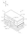
- FIG. 3 is a perspective view of the first magnetic induction foam molding apparatus.
- FIG. 4 shows a sectional view of the apparatus.
- the first magnetic induction foam molding apparatus 1 includes a pair of electromagnet portions 2U and 2D and a yoke portion 3.
- the electromagnet part 2U includes a core part 20U and a coil part 21U.
- the core portion 20U is made of a ferromagnetic material and has a cylindrical shape extending in the vertical direction.
- the coil portion 21U is disposed on the outer peripheral surface of the core portion 20U.
- the coil portion 21U is formed by a conducting wire 210U wound around the outer peripheral surface of the core portion 20U.
- the conducting wire 210U is connected to a power source (not shown).
- the electromagnet portion 2D is disposed below the electromagnet portion 2U with the foaming mold 4 interposed therebetween.
- the electromagnet part 2D has the same configuration as the electromagnet part 2U. That is, the electromagnet part 2D includes a core part 20D and a coil part 21D.
- the coil portion 21D is formed by a conducting wire 210D wound around the outer peripheral surface of the core portion 20D.
- the conducting wire 210D is connected to a power source (not shown).
- the yoke part 3 has a C shape.
- the C-shaped upper end of the yoke part 3 is connected to the upper end of the core part 20U of the electromagnet part 2U.
- the C-shaped lower end of the yoke part 3 is connected to the lower end of the core part 20D of the electromagnet part 2D.
- the foaming mold 4 includes an upper mold 40U and a lower mold 40D.
- the foaming mold 4 is interposed between the core part 20U of the electromagnet part 2U and the core part 20D of the electromagnet part 2D.
- the upper mold 40U has a prismatic shape.
- a cylindrical concave portion is formed on the lower surface of the upper mold 40U.
- the lower mold 40D has a prismatic shape.
- a cylindrical recess is formed on the upper surface of the lower mold 40D.
- the upper mold 40U and the lower mold 40D are arranged so that the openings of the recesses face each other.
- a cavity 41 is defined between the upper mold 40U and the lower mold 40D by combining the concave portions. As described above, the cavity 41 is filled with the mixed raw material.
- the lower end of the core portion 20U is an N pole
- the upper end of the core portion 20D is an S pole.
- lines of magnetic force L are generated from above to below between the core portion 20U and the core portion 20D.
- lines of magnetic force L are generated between the electromagnet portions 2U and 2D from the top to the bottom.
- the lines of magnetic force L radiated from the lower end of the core part 20D of the lower electromagnet part 2D flow through the yoke part 3 and flow into the upper end of the core part 20U of the upper electromagnet part 2U.
- the magnetic force line L comprises a closed loop, the leakage of the magnetic force line L can be suppressed.
- the foaming mold 4 is interposed between the core portion 20U and the core portion 20D. For this reason, a uniform magnetic field is formed in the cavity 41 of the foaming mold 4 by lines of magnetic force L that are substantially parallel from the top to the bottom. Specifically, the magnetic flux density in the cavity 41 was about 200 mT. Further, the difference in magnetic flux density in the cavity 41 was within ⁇ 3%.
- foam molding was performed while applying a magnetic field for the first approximately 2 minutes. For the next about 5 minutes, foam molding was performed without applying a magnetic field. After the foam molding was completed, the mold was removed to obtain a cylindrical urethane foam molded body.
- the obtained urethane foam molded article was made into the urethane foam molded article of Examples 1 and 2, corresponding to the number of the composite particles (thermally conductive filler).
- the thermally conductive fillers were connected to each other and oriented.
- thermal conductivities of the urethane foam moldings of Examples 1 and 2 and Comparative Example produced were measured.
- the thermal conductivity was measured by a hot wire method (probe method) based on JIS R2616 (2001).
- QTM-D3 manufactured by Kyoto Electronics Industry Co., Ltd. was used.
- FIG. 5 the measurement result of the thermal conductivity in each urethane foaming molding is shown.
- each curve indicates the thermal conductivity (approximately 0.04 W / mK) of the urethane foam molded article when the filler is not blended (blending amount 0% by volume), and the heat of each urethane foam molded article such as an example.
- each urethane foam molded body was 0.204 W / mK for Example 1 (the amount of heat conductive filler was 3.89% by volume), and 0.27 W / mK for Example 2 (the same amount). 3.42% by volume) and 0.198 W / mK for the comparative example (total blending amount of natural graphite powder and stainless steel powder: 4.12% by volume).
- the thermal conductivity of the urethane foam moldings of Examples 1 and 2 may be larger than the thermal conductivity of the urethane foam molding of the comparative example. Recognize. That is, according to the urethane foam moldings of Examples 1 and 2, it can be seen that the thermal conductivity is improved by a smaller amount of filler. In particular, according to the urethane foam molded article of Example 2 in which flaky magnetic particles were used as the composite particles, the thermal conductivity increased despite the small amount of the thermally conductive filler. The reason for this is that the contact area between the magnetic particles and the thermally conductive particles is increased, and the distance between the adjacent thermally conductive particles is shortened, thereby improving the thermal conductivity between the adjacent composite particles. It is thought that it was because.
- Expanded graphite powder (“SYZR502FP” purchased from Sanyo Trading Co., Ltd.) and natural graphite powder (same as above) are used as thermal conductive particles, and stainless steel powder (same as above) is used as magnetic particles.
- Manufactured First, expanded graphite powder, natural graphite powder, stainless steel powder, and hydroxypropylmethylcellulose (same as above) were put into a container of a high-speed stirring type mixing granulator (same as above) and mixed for about 3 minutes. Next, water was added and mixed for another 20 minutes. The obtained powder was dried to obtain composite particles A.
- the blending ratio of the materials used is shown in Table 1 below (the same applies to the following composite particles B to D).
- Composite particles B were produced in the same manner as the composite particles A except that the blending ratios of the magnetic particles and the binder were changed.
- Composite particles C were produced without using expanded graphite powder. That is, composite particles C were produced in the same manner as the composite particles A using natural graphite powder, stainless steel powder, and a binder. The composite particle C is the same as the composite particle of Example 1 in that expanded graphite particles are not included as the heat conductive particles.
- Composite particles D were produced without using natural graphite powder. That is, composite particles D were produced in the same manner as the composite particles A using expanded graphite powder, stainless steel powder, and a binder.
- a urethane foam molded article was produced using the produced composite particles A as a thermally conductive filler.
- the particles having expanded graphite particles as thermally conductive particles are 50% by mass
- the particles having natural graphite particles as thermally conductive particles are 50% by mass.
- a polyol raw material was prepared by mixing 0.5 parts by mass of a foam stabilizer (same as above).
- diphenylmethane diisocyanate (MDI) (same as above) was prepared as a polyisocyanate raw material.
- FIGS. 6 and 7 show a perspective view of the second magnetic induction foam molding apparatus.
- FIG. 7 shows a sectional view of the apparatus. In FIG. 7, for convenience of explanation, hatching of the yoke portion and the core portion is omitted.
- the second magnetic induction foam molding apparatus 5 includes a gantry 6, an electromagnet portion 7, and a foaming mold 8.
- the electromagnet portion 7 is placed on the top surface of the gantry 6.
- the electromagnet portion 7 and the gantry 6 are fixed by screwing a bracket 61 to each.
- the electromagnet portion 7 includes yoke portions 70U and 70D, coil portions 71L and 71R, and pole pieces 72U and 72D.
- the yoke part 70U is made of iron and has a flat plate shape.
- the yoke portion 70D is made of iron and has a flat plate shape.
- the yoke portions 70U and 70D are arranged to face each other in the vertical direction.
- the coil part 71L is interposed between the yoke parts 70U and 70D.
- the coil part 71 ⁇ / b> L is disposed on the left side of the foaming mold 8.
- Two coil portions 71L are arranged in the vertical direction.
- Each of the coil parts 71L includes a core part 710L and a conducting wire 711L.
- the core portion 710L is made of iron and has a columnar shape extending in the vertical direction.
- the conducting wire 711L is wound around the outer peripheral surface of the core portion 710L.
- the conducting wire 711L is connected to a power source (not shown).
- the coil portion 71R is interposed between the yoke portions 70U and 70D.
- the coil portion 71 ⁇ / b> R is disposed on the right side of the foaming mold 8.
- Two coil portions 71R are arranged in the vertical direction.
- the coil portions 71R each have the same configuration as the coil portion 71L. That is, the coil part 71R includes a core part 710R and a conducting wire 711R.
- the conducting wire 711R is wound around the outer peripheral surface of the core portion 710R.
- the conducting wire 711R is connected to a power source (not shown).
- the pole piece 72U is made of iron and has a flat plate shape.
- the pole piece 72U is disposed at the center of the lower surface of the yoke portion 70U.
- the pole piece 72U is interposed between the yoke portion 70U and the foaming mold 8.
- the pole piece 72D is made of iron and has a flat plate shape.
- the pole piece 72D is disposed at the center of the upper surface of the yoke portion 70D.
- the pole piece 72D is interposed between the yoke portion 70D and the foaming mold 8.
- the foaming mold 8 is disposed between the coil part 71L and the coil part 71R.
- the foaming mold 8 includes an upper mold 80U and a lower mold 80D.
- the upper mold 80U has a prismatic shape.
- a recess is formed in the lower surface of the upper mold 80U.
- the lower mold 80D has a prismatic shape.
- a recess is formed on the upper surface of the lower mold 80D.
- the upper mold 80U and the lower mold 80D are arranged so that the openings of the recesses face each other.
- a rectangular parallelepiped cavity 81 is defined between the upper mold 80U and the lower mold 80D by combining the concave portions. As described above, the cavity 81 is filled with the mixed raw material.
- Magnetic field lines L radiated from the upper end of the core portion 710L of the coil portion 71L flow into the cavity 81 of the foaming die 8 through the yoke portion 70U and the pole piece 72U. Then, it flows into the lower end of the core part 710L through the pole piece 72D and the yoke part 70D.
- the lines of magnetic force L radiated from the upper end of the core portion 710R of the coil portion 71R flow into the cavity 81 of the foaming mold 8 through the yoke portion 70U and the pole piece 72U. Then, it flows into the lower end of the core portion 710R through the pole piece 72D and the yoke portion 70D.
- the magnetic lines L constitute a closed loop, the leakage of the magnetic lines L is suppressed. Further, a uniform magnetic field is formed in the cavity 81 of the foaming mold 8 by the magnetic force lines L that are substantially parallel from the top to the bottom. Specifically, the magnetic flux density in the cavity 81 was about 200 mT. Further, the difference in magnetic flux density in the cavity 81 was within ⁇ 3%.
- Foam molding was performed while applying a magnetic field for the first approximately 2 minutes and without applying a magnetic field for the subsequent approximately 5 minutes. After the foam molding was completed, the mold was removed to obtain a urethane foam molded article. The obtained urethane foam molded article was used as the urethane foam molded article of Example 3. In the urethane foam molded article of Example 3, the content of the thermally conductive filler (composite particles A) was 4% by volume when the volume of the urethane foam molded article was 100% by volume.
- Example 4 Using the produced composite particle B as a thermally conductive filler, a urethane foam molded article was produced.
- the composite particles B 50% by mass is particles with expanded graphite particles as thermally conductive particles, and 50% by mass with natural graphite particles as thermally conductive particles.
- 381 g of the premix polyol and 15.1 g of the polyisocyanate raw material used in Example 3 were mixed to obtain a mixed raw material.
- the mixed raw material was poured into a foaming mold (same as above), the foaming mold was sealed, and foam molding was performed in a magnetic field in the same manner as in Example 3.
- the obtained urethane foam molded article was used as the urethane foam molded article of Example 4.
- the content of the heat conductive filler (composite particle B) was 19.3 volume% when the volume of the urethane foam molded article was 100 volume%.
- Example 5 A urethane foam molded article was produced using the produced composite particles D as a thermally conductive filler.
- the thermally conductive particles constituting the composite particle D are all expanded graphite particles.
- 129.7 parts by mass of composite particles D were added to and mixed with 100 parts by mass of the polyol raw material used in Example 3 to prepare a premix polyol.
- 100.6 g of the premix polyol and 13.7 g of the polyisocyanate raw material used in Example 3 were mixed to obtain a mixed raw material.
- the mixed raw material was poured into a foaming mold (same as above), the foaming mold was sealed, and foam molding was performed in a magnetic field in the same manner as in Example 3.
- the obtained urethane foam molded article was used as the urethane foam molded article of Example 5.
- the content of the thermally conductive filler (composite particles D) was 4% by volume when the volume of the urethane foam molded article was 100% by volume.
- a urethane foam molded article was produced.
- the heat conductive particles constituting the composite particle C are all natural graphite particles.
- 129.7 parts by mass of composite particles C were added and mixed to prepare a premix polyol.
- 100.6 g of the premix polyol and 13.7 g of the polyisocyanate raw material used in Example 3 were mixed to obtain a mixed raw material.
- the mixed raw material was poured into a foaming mold (same as above), the foaming mold was sealed, and foam molding was performed in a magnetic field in the same manner as in Example 3.
- the obtained urethane foam molded article was used as a urethane foam molded article of Reference Example.
- the content of the heat conductive filler (composite particles C) was 4% by volume when the volume of the urethane foam molded article was 100% by volume.
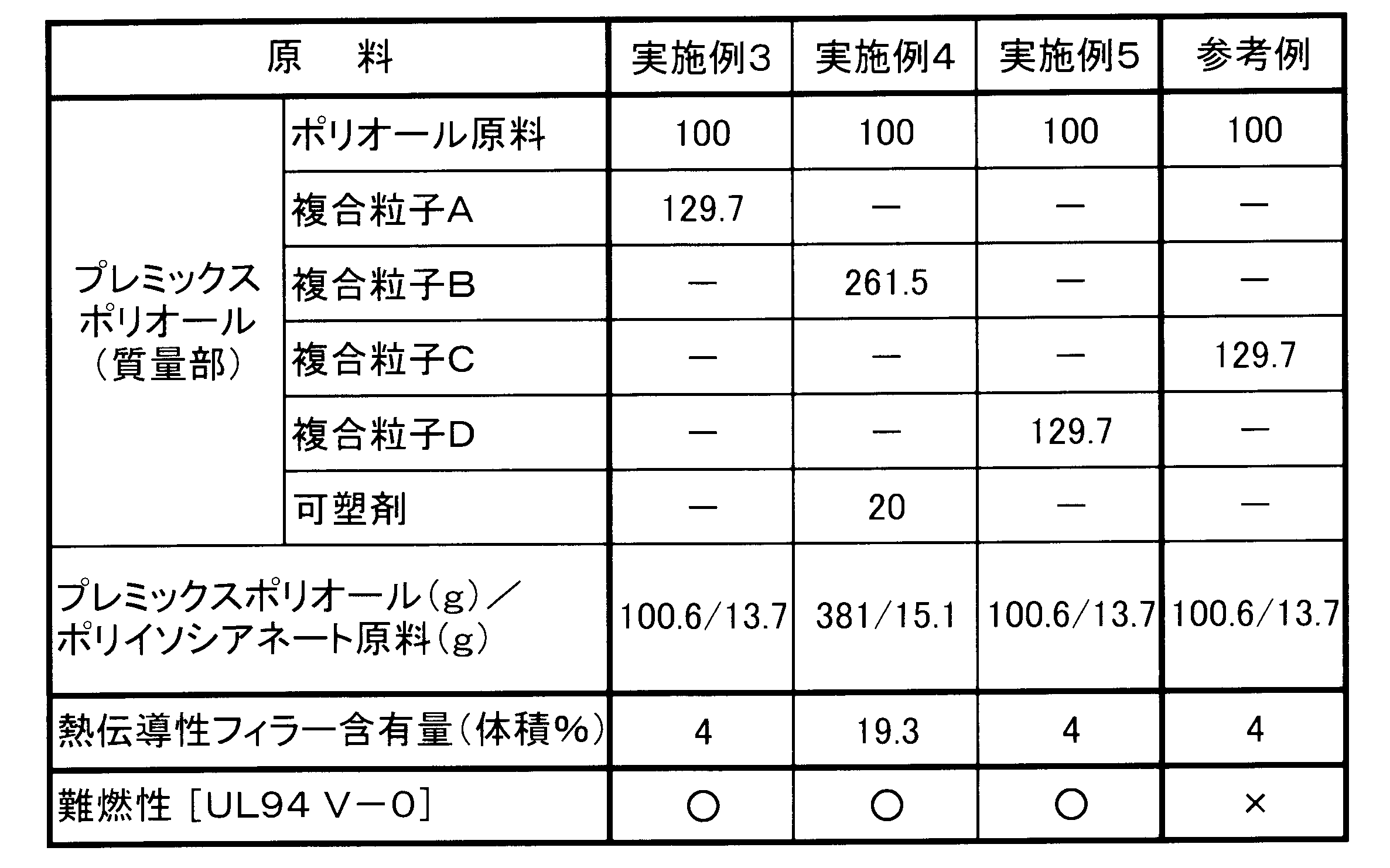
- the UL foam V-0 standard was cleared for each urethane foam molded body of the example.
- the urethane foam molded article of the reference example that does not contain expanded graphite particles as the heat conductive particles could not achieve the flame retardancy based on V-0.
- expanded graphite particles were used as the thermally conductive particles, it was confirmed that the urethane foam molded article of the present invention was excellent in flame retardancy even if it contained magnetic particles.
- the urethane foam molded article of the present invention can be used in a wide range of fields such as automobiles, electronic equipment, and architecture. In addition to heat dissipation, it can also be used for applications that require high flame retardancy. For example, soundproof tires to reduce noise caused by road surface unevenness, engine covers and side covers arranged in the engine room of vehicles to reduce engine noise, motors for office automation (OA) equipment and household appliances It is suitable as a sound absorbing material for a computer, a heat radiating sound absorbing material for an electronic device such as a personal computer, a sound absorbing material for inner and outer walls of a house, and a vibration isolating material used for a reactor for a power conditioner of a solar power generation system.
- OA office automation
Landscapes
- Chemical & Material Sciences (AREA)
- Health & Medical Sciences (AREA)
- Chemical Kinetics & Catalysis (AREA)
- Medicinal Chemistry (AREA)
- Polymers & Plastics (AREA)
- Organic Chemistry (AREA)
- Casting Or Compression Moulding Of Plastics Or The Like (AREA)
- Polyurethanes Or Polyureas (AREA)
- Compositions Of Macromolecular Compounds (AREA)
Abstract
Description
2U、2D:電磁石部 20U、20D:芯部 21U、21D:コイル部 210U、210D:導線 3:ヨーク部 4:発泡型 40U:上型 40D:下型 41:キャビティ
5:第二磁気誘導発泡成形装置
6:架台 61:ブラケット 7:電磁石部 70D、70U:ヨーク部 71L、71R:コイル部 72D、72U:ポールピース 710L、710R:芯部 711L、711R:導線 8:発泡型 80U:上型 80D:下型 81:キャビティ
L:磁力線
本発明のウレタン発泡成形体は、ポリウレタンフォームからなる基材と、該基材中に配合され互いに連接して配向している熱伝導性フィラーと、を有する。
本発明のウレタン発泡成形体の製造方法は、原料混合工程と発泡成形工程とを有する。以下、各工程について説明する。
本工程は、発泡ウレタン樹脂原料と、熱伝導性フィラーと、を混合して混合原料とする工程である。
本工程は、先の原料混合工程にて得られた混合原料を発泡型のキャビティ内に注入し、該キャビティ内の磁束密度が略均一になるように磁場をかけながら発泡成形する工程である。
<複合粒子の製造>
次のようにして、二種類の複合粒子を製造した。まず、熱伝導性粒子としての天然黒鉛粉末(日本黒鉛工業(株)製「F♯2」、薄片状、平均粒子径130μm、熱伝導率250W/m・K)と、磁性粒子としてのステンレス鋼粉末(大同特殊鋼(株)製「DAP410L」、SUS410、球状、平均粒子径10μm)と、バインダーとしてのヒドロキシプロピルメチルセルロース(信越化学工業(株)製「TC-5」)と、を準備した。次に、天然黒鉛粉末、ステンレス鋼粉末、およびヒドロキシプロピルメチルセルロースを、高速攪拌型混合造粒機((株)奈良機械製作所製「NMG-1L」)の容器内へ投入して、約3分間混合した。天然黒鉛粉末とステンレス鋼粉末との配合割合は、体積比で6:4とした。また、ヒドロキシプロピルメチルセルロースの配合割合は、天然黒鉛粉末およびステンレス鋼粉末の合計質量を100質量%とした場合の、2質量%とした。その後、水を添加して、さらに20分間混合した。得られた粉末を乾燥した後、目開き500μmの篩いにより篩い分けして、最大長さが500μm以下の粒子を回収した。このようにして、実施例1の複合粒子を製造した。
[実施例1、2]
製造した二種類の複合粒子を、各々、熱伝導性フィラーとして配合して、ウレタン発泡成形体を製造した。まず、発泡ウレタン樹脂原料を、次のようにして調製した。ポリオール成分のポリエーテルポリオール(住化バイエルウレタン(株)製「S-0248」、平均分子量6000、官能基数3、OH価28mgKOH/g)100質量部と、架橋剤のジエチレングリコール(三菱化学(株)製)2質量部と、発泡剤の水2質量部と、テトラエチレンジアミン系触媒(花王(株)製「カオーライザー(登録商標)No.31」)1質量部と、シリコーン系整泡剤(東レ・ダウコーニング(株)製「SZ-1313」)0.5質量部と、を混合して、ポリオール原料を調製した。調製したポリオール原料に、ポリイソシアネート成分のジフェニルメタンジイソシアネート(MDI)(BASFINOACポリウレタン(株)製「NE1320B」、NCO=44.8wt%)を加えて混合し、発泡ウレタン樹脂原料とした。ここで、ポリオール成分とポリイソシアネート成分との配合比(PO:ISO)は、両者の合計質量を100%として、PO:ISO=78.5:21.5とした。
実施例1の複合粒子の製造に使用した天然黒鉛粉末(熱伝導性粒子)と、ステンレス鋼粉末(球状の磁性粒子)と、を複合化せずに、各々単体として配合した点以外は、上記実施例1、2と同様にして、ウレタン発泡成形体を製造した。天然黒鉛粉末については、製造するウレタン発泡成形体の体積を100体積%とした場合の2.34体積%、ステンレス鋼粉末については、1.78体積%、となるように配合した。得られたウレタン発泡成形体を、比較例のウレタン発泡成形体とした。
製造した実施例1、2および比較例のウレタン発泡成形体の熱伝導率を測定した。熱伝導率は、JIS R2616(2001)に準拠した熱線法(プローブ法)により測定した。測定には、京都電子工業(株)製「QTM-D3」を使用した。図5に、各ウレタン発泡成形体における熱伝導率の測定結果を示す。図5中、各曲線は、フィラーを配合しない場合(配合量0体積%)のウレタン発泡成形体の熱伝導率(約0.04W/mK)と、実施例等の各ウレタン発泡成形体の熱伝導率と、を結んだ近似曲線である。各ウレタン発泡成形体の熱伝導率は、実施例1については0.204W/mK(熱伝導性フィラーの配合量3.89体積%)、実施例2については0.207W/mK(同配合量3.42体積%)、比較例については0.198W/mK(天然黒鉛粉末およびステンレス鋼粉末の合計配合量4.12体積%)であった。
<複合粒子の製造>
次のようにして、A~Dの四種類の複合粒子を製造した。
熱伝導性粒子として、膨張黒鉛粉末(三洋貿易(株)から購入した「SYZR502FP」)、および天然黒鉛粉末(同上)を用い、磁性粒子として、ステンレス鋼粉末(同上)を用いて、複合粒子を製造した。まず、膨張黒鉛粉末と、天然黒鉛粉末と、ステンレス鋼粉末と、ヒドロキシプロピルメチルセルロース(同上)と、を高速攪拌型混合造粒機(同上)の容器内へ投入して、約3分間混合した。次に、水を添加して、さらに20分間混合した。得られた粉末を乾燥して、複合粒子Aを得た。なお、使用した材料の配合割合については、下記表1に示す(以下の複合粒子B~Dについても同じ)。
磁性粒子、バインダーの配合割合を、各々変更した以外は、上記複合粒子Aと同様にして、複合粒子Bを製造した。
膨張黒鉛粉末を用いずに、複合粒子Cを製造した。すなわち、天然黒鉛粉末、ステンレス鋼粉末、およびバインダーを用いて、上記複合粒子Aと同様にして、複合粒子Cを製造した。熱伝導性粒子として膨張黒鉛粒子を含まないという点において、複合粒子Cは、上記実施例1の複合粒子と同じである。
天然黒鉛粉末を用いずに、複合粒子Dを製造した。すなわち、膨張黒鉛粉末、ステンレス鋼粉末、およびバインダーを用いて、上記複合粒子Aと同様にして、複合粒子Dを製造した。

[実施例3]
製造した複合粒子Aを熱伝導性フィラーとして用いて、ウレタン発泡成形体を製造した。複合粒子Aのうち、膨張黒鉛粒子を熱伝導性粒子とする粒子は50質量%、天然黒鉛粒子を熱伝導性粒子とする粒子は50質量%である。まず、ポリエーテルポリオール(同上)100質量部と、架橋剤のジエチレングリコール(同上)2質量部と、発泡剤の水2質量部と、テトラエチレンジアミン系触媒(同上)1.5質量部と、シリコーン系整泡剤(同上)0.5質量部と、を混合して、ポリオール原料を調製した。また、ポリイソシアネート原料として、ジフェニルメタンジイソシアネート(MDI)(同上)を準備した。
製造した複合粒子Bを熱伝導性フィラーとして用いて、ウレタン発泡成形体を製造した。複合粒子Bのうち、膨張黒鉛粒子を熱伝導性粒子とする粒子は50質量%、天然黒鉛粒子を熱伝導性粒子とする粒子は50質量%である。まず、上記実施例3で使用したポリオール原料100質量部に、複合粒子B261.5質量部と、可塑剤20質量部と、を添加、混合して、プレミックスポリオールを調製した。次に、プレミックスポリオール381gと、上記実施例3で使用したポリイソシアネート原料15.1gと、を混合して、混合原料とした。そして、混合原料を発泡型(同上)に注入し、発泡型を密閉して、上記実施例3と同様に、磁場中で発泡成形を行った。得られたウレタン発泡成形体を、実施例4のウレタン発泡成形体とした。実施例4のウレタン発泡成形体において、熱伝導性フィラー(複合粒子B)の含有量は、ウレタン発泡成形体の体積を100体積%とした場合の19.3体積%であった。
製造した複合粒子Dを熱伝導性フィラーとして用いて、ウレタン発泡成形体を製造した。複合粒子Dを構成する熱伝導性粒子は、全て膨張黒鉛粒子である。まず、上記実施例3で使用したポリオール原料100質量部に、複合粒子D129.7質量部を添加、混合して、プレミックスポリオールを調製した。次に、プレミックスポリオール100.6gと、上記実施例3で使用したポリイソシアネート原料13.7gと、を混合して、混合原料とした。そして、混合原料を発泡型(同上)に注入し、発泡型を密閉して、上記実施例3と同様に、磁場中で発泡成形を行った。得られたウレタン発泡成形体を、実施例5のウレタン発泡成形体とした。実施例5のウレタン発泡成形体において、熱伝導性フィラー(複合粒子D)の含有量は、ウレタン発泡成形体の体積を100体積%とした場合の4体積%であった。
製造した複合粒子Cを熱伝導性フィラーとして用いて、ウレタン発泡成形体を製造した。複合粒子Cを構成する熱伝導性粒子は、全て天然黒鉛粒子である。まず、上記実施例3で使用したポリオール原料100質量部に、複合粒子C129.7質量部を添加、混合して、プレミックスポリオールを調製した。次に、プレミックスポリオール100.6gと、上記実施例3で使用したポリイソシアネート原料13.7gと、を混合して、混合原料とした。そして、混合原料を発泡型(同上)に注入し、発泡型を密閉して、上記実施例3と同様に、磁場中で発泡成形を行った。得られたウレタン発泡成形体を、参考例のウレタン発泡成形体とした。参考例のウレタン発泡成形体において、熱伝導性フィラー(複合粒子C)の含有量は、ウレタン発泡成形体の体積を100体積%とした場合の4体積%であった。
実施例および参考例の各ウレタン発泡成形体について、難燃性を評価した。難燃性の評価は、米国のUnderwriters Laboratories,Inc.により制定された燃焼試験規格(UL94)に基づいて、行った。そして、「V-0」の判定基準を満たした場合を合格(表2中○印で示す)、満たさなかった場合を不合格(表2中×印で示す)と評価した。評価結果を、各ウレタン発泡成形体における原料の配合量と共に、表2に示す。
Claims (13)
- ポリウレタンフォームからなる基材と、該基材中に配合され互いに連接して配向している熱伝導性フィラーと、を有し、
該熱伝導性フィラーは、非磁性体からなる熱伝導性粒子と、該熱伝導性粒子の表面に付着された磁性粒子と、を有する複合粒子からなることを特徴とするウレタン発泡成形体。 - 前記磁性粒子は、薄片状を呈している請求項1に記載のウレタン発泡成形体。
- 前記磁性粒子は、鉄、ニッケル、コバルト、およびこれらの鉄系合金から選ばれる一種以上からなる請求項1または請求項2に記載のウレタン発泡成形体。
- 前記磁性粒子の平均粒子径は、1μm以上である請求項1ないし請求項3のいずれかに記載のウレタン発泡成形体。
- 前記熱伝導性粒子の平均粒子径は、500μm以下である請求項1ないし請求項4のいずれかに記載のウレタン発泡成形体。
- 前記複合粒子は、攪拌造粒法により製造されており、
前記熱伝導性粒子と前記磁性粒子とは、バインダーにより接着されている請求項1ないし請求項5のいずれかに記載のウレタン発泡成形体。 - 前記熱伝導性粒子は、黒鉛からなる請求項1ないし請求項6のいずれかに記載のウレタン発泡成形体。
- 前記複合粒子における前記黒鉛と前記磁性粒子との体積割合は、7:3~5:5である請求項7に記載のウレタン発泡成形体。
- 前記熱伝導性粒子は、膨張黒鉛粒子を含む請求項1ないし請求項8のいずれかに記載のウレタン発泡成形体。
- 前記熱伝導性粒子は、さらに膨張黒鉛以外の黒鉛粒子を含む請求項9に記載のウレタン発泡成形体。
- 前記膨張黒鉛粒子の含有量は、ウレタン発泡成形体全体の質量を100質量%とした場合の5質量%以上である請求項9または請求項10に記載のウレタン発泡成形体。
- 前記複合粒子の表面は、絶縁層で被覆されている請求項1ないし請求項11のいずれかに記載のウレタン発泡成形体。
- 請求項1ないし請求項12のいずれかに記載のウレタン発泡成形体の製造方法であって、
発泡ウレタン樹脂原料と、前記熱伝導性フィラーと、を混合して混合原料とする原料混合工程と、
該混合原料を発泡型のキャビティ内に注入し、該キャビティ内の磁束密度が略均一になるように磁場をかけながら発泡成形する発泡成形工程と、
を有することを特徴とするウレタン発泡成形体の製造方法。
Priority Applications (3)
| Application Number | Priority Date | Filing Date | Title |
|---|---|---|---|
| CN2011800013010A CN102341225A (zh) | 2010-03-30 | 2011-03-24 | 聚氨酯发泡成形体及其制造方法 |
| DE112011100007.3T DE112011100007B4 (de) | 2010-03-30 | 2011-03-24 | Urethanschaum-Formteil und Verfahren zu dessen Herstellung |
| US13/203,176 US9034935B2 (en) | 2010-03-30 | 2011-03-24 | Urethane foam molded product and method for producing the same |
Applications Claiming Priority (4)
| Application Number | Priority Date | Filing Date | Title |
|---|---|---|---|
| JP2010078503 | 2010-03-30 | ||
| JP2010-078503 | 2010-03-30 | ||
| JP2010194130A JP5662743B2 (ja) | 2010-08-31 | 2010-08-31 | ウレタン発泡成形体およびその製造方法 |
| JP2010-194130 | 2010-08-31 |
Publications (1)
| Publication Number | Publication Date |
|---|---|
| WO2011122441A1 true WO2011122441A1 (ja) | 2011-10-06 |
Family
ID=44712150
Family Applications (1)
| Application Number | Title | Priority Date | Filing Date |
|---|---|---|---|
| PCT/JP2011/057192 Ceased WO2011122441A1 (ja) | 2010-03-30 | 2011-03-24 | ウレタン発泡成形体およびその製造方法 |
Country Status (4)
| Country | Link |
|---|---|
| US (1) | US9034935B2 (ja) |
| CN (1) | CN102341225A (ja) |
| DE (1) | DE112011100007B4 (ja) |
| WO (1) | WO2011122441A1 (ja) |
Cited By (6)
| Publication number | Priority date | Publication date | Assignee | Title |
|---|---|---|---|---|
| US20140231700A1 (en) * | 2011-12-27 | 2014-08-21 | Panasonic Corporation | Thermoconductive resin composition |
| EP2682411A4 (en) * | 2011-09-20 | 2015-01-14 | Sumitomo Riko Co Ltd | URETHANEUM FUEL FORMPRODUCT AND METHOD FOR THE PRODUCTION THEREOF |
| JP2015105282A (ja) * | 2013-11-28 | 2015-06-08 | 住友理工株式会社 | エラストマー成形体およびその製造方法 |
| EP3987605A1 (de) * | 2019-06-18 | 2022-04-27 | Audi AG | Verfahren zum einbringen einer wärmeleitfähigen füllmasse mit variablem anteil an füllstoff, batteriemodulvorrichtung und anlage zum einbringen von füllmasse |
| JP2023016623A (ja) * | 2021-07-22 | 2023-02-02 | 株式会社イノアックコーポレーション | ポリウレタンフォーム、ポリオール組成物及びポリウレタンフォームの製造方法 |
| WO2025004471A1 (ja) * | 2023-06-30 | 2025-01-02 | 住友理工株式会社 | ウレタン発泡成形体 |
Families Citing this family (10)
| Publication number | Priority date | Publication date | Assignee | Title |
|---|---|---|---|---|
| JP6657601B2 (ja) * | 2014-08-08 | 2020-03-04 | 株式会社リコー | 立体造形用粉末材料、立体造形材料セット、及び立体造形物の製造方法 |
| WO2017165340A1 (en) * | 2016-03-21 | 2017-09-28 | Hubbell Incorporated | Noise reducing and cooling enclosure |
| KR102056098B1 (ko) * | 2016-04-01 | 2019-12-17 | 주식회사 엘지화학 | 금속폼의 제조 방법 |
| JP6729873B2 (ja) * | 2016-07-04 | 2020-07-29 | トヨタ紡織株式会社 | ウレタン発泡成形用補強用布状物およびこれを利用したウレタン発泡成形体の製造方法 |
| US10525643B2 (en) * | 2017-05-03 | 2020-01-07 | Covestro Llc | Methods for making foam laminates having a concave surface and laminates produced thereby |
| CN107955200B (zh) * | 2017-11-29 | 2020-06-09 | 三峡大学 | 一种石墨烯/有机物复合微粒及其制备方法 |
| US11760136B2 (en) | 2018-05-15 | 2023-09-19 | Bridgestone Americas Tire Operations, Llc | Tire with multi-layer insert |
| EP3808525A1 (en) * | 2019-10-14 | 2021-04-21 | SHPP Global Technologies B.V. | Improved through-plane thermal conductivity using foam injection molding with core-back technology |
| CN114161803A (zh) * | 2020-09-11 | 2022-03-11 | 北京服装学院 | 一种新型复合式磁化tpu材料 |
| CN115433389A (zh) * | 2022-10-19 | 2022-12-06 | 安徽大学 | 一种两步法构建的双重导热网络聚氨酯导热复合材料及其制备方法 |
Citations (3)
| Publication number | Priority date | Publication date | Assignee | Title |
|---|---|---|---|---|
| JP2003321554A (ja) * | 2002-04-26 | 2003-11-14 | Polymatech Co Ltd | 熱伝導性成形体及びその製造方法 |
| JP2006219562A (ja) * | 2005-02-09 | 2006-08-24 | Toyo Tire & Rubber Co Ltd | 硬質ポリウレタンフォーム、硬質ポリウレタンフォーム用ポリオール組成物及び硬質ポリウレタンフォームの製造方法 |
| JP2009051148A (ja) * | 2007-08-28 | 2009-03-12 | Tokai Rubber Ind Ltd | ウレタン発泡成形体およびその製造方法 |
Family Cites Families (6)
| Publication number | Priority date | Publication date | Assignee | Title |
|---|---|---|---|---|
| DE3616507C1 (en) | 1986-05-16 | 1987-07-30 | Gebr. Happich Gmbh, 5600 Wuppertal, De | Cushion material mfr. - from moulded foam having at least two different hardness areas |
| JP3546033B2 (ja) | 2001-09-27 | 2004-07-21 | 東海ゴム工業株式会社 | 車両用難燃性防音・防振材及びその製造方法 |
| JP4709609B2 (ja) | 2005-08-08 | 2011-06-22 | 株式会社イノアックコーポレーション | 難燃性遮音材、及びその製造方法 |
| JP4906527B2 (ja) | 2006-01-31 | 2012-03-28 | 東海ゴム工業株式会社 | 吸音体及び吸音構造体 |
| WO2008104491A1 (de) | 2007-02-28 | 2008-09-04 | Basf Se | Schaumstoffe mit veränderbaren mechanischen eigenschaften |
| US8734669B2 (en) * | 2007-08-28 | 2014-05-27 | Tokai Rubber Industries, Ltd. | Urethane foam molded article, manufacturing method thereof, and magnetic induction foam molding apparatus |
-
2011
- 2011-03-24 WO PCT/JP2011/057192 patent/WO2011122441A1/ja not_active Ceased
- 2011-03-24 US US13/203,176 patent/US9034935B2/en active Active
- 2011-03-24 CN CN2011800013010A patent/CN102341225A/zh active Pending
- 2011-03-24 DE DE112011100007.3T patent/DE112011100007B4/de active Active
Patent Citations (3)
| Publication number | Priority date | Publication date | Assignee | Title |
|---|---|---|---|---|
| JP2003321554A (ja) * | 2002-04-26 | 2003-11-14 | Polymatech Co Ltd | 熱伝導性成形体及びその製造方法 |
| JP2006219562A (ja) * | 2005-02-09 | 2006-08-24 | Toyo Tire & Rubber Co Ltd | 硬質ポリウレタンフォーム、硬質ポリウレタンフォーム用ポリオール組成物及び硬質ポリウレタンフォームの製造方法 |
| JP2009051148A (ja) * | 2007-08-28 | 2009-03-12 | Tokai Rubber Ind Ltd | ウレタン発泡成形体およびその製造方法 |
Cited By (8)
| Publication number | Priority date | Publication date | Assignee | Title |
|---|---|---|---|---|
| EP2682411A4 (en) * | 2011-09-20 | 2015-01-14 | Sumitomo Riko Co Ltd | URETHANEUM FUEL FORMPRODUCT AND METHOD FOR THE PRODUCTION THEREOF |
| US9399706B2 (en) | 2011-09-20 | 2016-07-26 | Sumitomo Riko Company Limited | Urethane foam molded product and method for producing the same |
| US20140231700A1 (en) * | 2011-12-27 | 2014-08-21 | Panasonic Corporation | Thermoconductive resin composition |
| JP2015105282A (ja) * | 2013-11-28 | 2015-06-08 | 住友理工株式会社 | エラストマー成形体およびその製造方法 |
| EP3987605A1 (de) * | 2019-06-18 | 2022-04-27 | Audi AG | Verfahren zum einbringen einer wärmeleitfähigen füllmasse mit variablem anteil an füllstoff, batteriemodulvorrichtung und anlage zum einbringen von füllmasse |
| JP2023016623A (ja) * | 2021-07-22 | 2023-02-02 | 株式会社イノアックコーポレーション | ポリウレタンフォーム、ポリオール組成物及びポリウレタンフォームの製造方法 |
| JP7759745B2 (ja) | 2021-07-22 | 2025-10-24 | 株式会社イノアックコーポレーション | ポリウレタンフォーム、ポリオール組成物及びポリウレタンフォームの製造方法 |
| WO2025004471A1 (ja) * | 2023-06-30 | 2025-01-02 | 住友理工株式会社 | ウレタン発泡成形体 |
Also Published As
| Publication number | Publication date |
|---|---|
| DE112011100007B4 (de) | 2014-07-24 |
| DE112011100007T5 (de) | 2012-06-28 |
| US9034935B2 (en) | 2015-05-19 |
| US20130001460A1 (en) | 2013-01-03 |
| CN102341225A (zh) | 2012-02-01 |
Similar Documents
| Publication | Publication Date | Title |
|---|---|---|
| JP5766477B2 (ja) | ウレタン発泡成形体およびその製造方法 | |
| WO2011122441A1 (ja) | ウレタン発泡成形体およびその製造方法 | |
| JP5829279B2 (ja) | ウレタン発泡成形体およびその製造方法 | |
| JP5662743B2 (ja) | ウレタン発泡成形体およびその製造方法 | |
| JP5026892B2 (ja) | ウレタン発泡成形体およびその製造方法 | |
| JP2015030735A (ja) | エラストマー成形体およびその製造方法 | |
| JP5577065B2 (ja) | ウレタン発泡成形体およびその製造方法 | |
| US12441035B2 (en) | Urethane foam-molded article and method for producing same | |
| JP2012153079A (ja) | ウレタン発泡成形体およびその製造方法 | |
| JP5302547B2 (ja) | ウレタン発泡成形体、その製造方法、および磁気誘導発泡成形装置 | |
| JP2014065159A (ja) | ウレタン発泡成形体およびその製造方法 | |
| JP5097092B2 (ja) | ウレタン発泡成形体およびその製造方法 | |
| JP5118988B2 (ja) | ウレタン発泡成形体およびその製造方法 | |
| JP2025086109A (ja) | ウレタン発泡成形体 | |
| JP2025006977A (ja) | ウレタン発泡成形体 | |
| JP2025006980A (ja) | ウレタン発泡成形体 | |
| US20250297102A1 (en) | Urethane foam molded body | |
| JP2025025262A (ja) | ウレタン発泡成形体およびそれを用いた放熱構造体 |
Legal Events
| Date | Code | Title | Description |
|---|---|---|---|
| WWE | Wipo information: entry into national phase |
Ref document number: 201180001301.0 Country of ref document: CN |
|
| WWE | Wipo information: entry into national phase |
Ref document number: 13203176 Country of ref document: US |
|
| WWE | Wipo information: entry into national phase |
Ref document number: 1120111000073 Country of ref document: DE Ref document number: 112011100007 Country of ref document: DE |
|
| 121 | Ep: the epo has been informed by wipo that ep was designated in this application |
Ref document number: 11762672 Country of ref document: EP Kind code of ref document: A1 |
|
| 122 | Ep: pct application non-entry in european phase |
Ref document number: 11762672 Country of ref document: EP Kind code of ref document: A1 |