WO2011122435A1 - 膨張弁 - Google Patents
膨張弁 Download PDFInfo
- Publication number
- WO2011122435A1 WO2011122435A1 PCT/JP2011/057150 JP2011057150W WO2011122435A1 WO 2011122435 A1 WO2011122435 A1 WO 2011122435A1 JP 2011057150 W JP2011057150 W JP 2011057150W WO 2011122435 A1 WO2011122435 A1 WO 2011122435A1
- Authority
- WO
- WIPO (PCT)
- Prior art keywords
- power element
- valve body
- closing member
- passage
- expansion valve
- Prior art date
- Legal status (The legal status is an assumption and is not a legal conclusion. Google has not performed a legal analysis and makes no representation as to the accuracy of the status listed.)
- Ceased
Links
Images




Classifications
-
- F—MECHANICAL ENGINEERING; LIGHTING; HEATING; WEAPONS; BLASTING
- F25—REFRIGERATION OR COOLING; COMBINED HEATING AND REFRIGERATION SYSTEMS; HEAT PUMP SYSTEMS; MANUFACTURE OR STORAGE OF ICE; LIQUEFACTION SOLIDIFICATION OF GASES
- F25B—REFRIGERATION MACHINES, PLANTS OR SYSTEMS; COMBINED HEATING AND REFRIGERATION SYSTEMS; HEAT PUMP SYSTEMS
- F25B41/00—Fluid-circulation arrangements
- F25B41/30—Expansion means; Dispositions thereof
- F25B41/31—Expansion valves
- F25B41/33—Expansion valves with the valve member being actuated by the fluid pressure, e.g. by the pressure of the refrigerant
- F25B41/335—Expansion valves with the valve member being actuated by the fluid pressure, e.g. by the pressure of the refrigerant via diaphragms
-
- F—MECHANICAL ENGINEERING; LIGHTING; HEATING; WEAPONS; BLASTING
- F25—REFRIGERATION OR COOLING; COMBINED HEATING AND REFRIGERATION SYSTEMS; HEAT PUMP SYSTEMS; MANUFACTURE OR STORAGE OF ICE; LIQUEFACTION SOLIDIFICATION OF GASES
- F25B—REFRIGERATION MACHINES, PLANTS OR SYSTEMS; COMBINED HEATING AND REFRIGERATION SYSTEMS; HEAT PUMP SYSTEMS
- F25B2341/00—Details of ejectors not being used as compression device; Details of flow restrictors or expansion valves
- F25B2341/06—Details of flow restrictors or expansion valves
- F25B2341/068—Expansion valves combined with a sensor
- F25B2341/0683—Expansion valves combined with a sensor the sensor is disposed in the suction line and influenced by the temperature or the pressure of the suction gas
Definitions
- the present invention relates to an expansion valve that is incorporated in a refrigeration cycle and controls the flow rate of refrigerant flowing through an orifice according to the temperature of the refrigerant.
- a high-pressure liquid-phase refrigerant from a condenser is passed through an orifice to a low pressure and sent to an evaporator (evaporator), and from the evaporator to a compressor.
- evaporator evaporator
- a temperature expansion valve with a built-in temperature sensing mechanism that adjusts the amount of refrigerant passing by allowing the low-pressure gas-phase refrigerant to pass through and controlling the orifice opening according to the temperature and pressure of the gas-phase refrigerant.
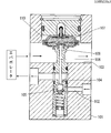
- the expansion valve disclosed in the above-mentioned Patent Document 1 is provided with a first passage 102 through which refrigerant from the condenser to the evaporator passes, and is provided above the first passage 102 and from the evaporator to the compressor.
- the valve body 101 having the orifice 104 provided in the middle of the second passage 103 and the first passage 102 through which the refrigerant is directed and the valve seat 104a formed at the lower end of the orifice 104 are contacted and separated to open and close the orifice 104.
- the flow rate of the refrigerant circulating in the refrigeration cycle is controlled according to the degree of load.
- the attachment of the power element 107 to the valve body 101 is performed by screwing a male screw 107a formed on the power element and a female screw 101a formed on the valve body 101.
- a male screw 107a formed on the power element and a female screw 101a formed on the valve body 101 it is necessary to thread the male screw and the female screw, which is a factor that causes an increase in the manufacturing cost of the expansion valve.
- the valve body 101 and the power element 107 are sealed with a separate seal member 108.
- the member 108 causes an increase in the number of parts and an increase in manufacturing cost.
- FIG. 9 shows a longitudinal sectional view of an example of an expansion valve that solves such a problem.
- the power element 107 is fixed to a projecting end portion 109 provided so as to protrude into the second passage 103, and a recess 110 provided on the ceiling of the second passage 103.
- the power element 107 is disposed in the front.
- the diaphragm driving medium enclosed in the power element 107 is less affected by the outside air temperature, so that the diaphragm driving medium accurately senses the temperature of the refrigerant flowing through the second passage 103.
- Patent Document 2 shows a longitudinal sectional view of an example of an expansion valve that solves such a problem.
- the power element 107 is fixed to a protruding end 109 that protrudes into the second passage 103, and a part of the protruding end 109 and the lower part of the power element 107 are below. Becomes a resistance to the refrigerant flowing through the second passage 103, causing a pressure loss of the refrigerant.
- JP 2008-180476 A Microfilm of Japanese Utility Model Application Sho 62-85873 (Japanese Utility Model Application No. 63-196058)
- the present invention has been made in view of the above-described problems, and a first object thereof is to manufacture a screw element for fixing the power element to the valve body and a seal member for sealing the periphery of the power element.
- An object of the present invention is to provide an expansion valve capable of reducing the cost.
- the second object of the present invention is to improve the accuracy of refrigerant flow rate control by making the power element less susceptible to outside air temperature, and to reduce the pressure loss of the low-pressure refrigerant from the evaporator to the compressor. It is to provide an expansion valve.
- the first expansion valve according to the present invention includes a first passage through which a refrigerant from the condenser to the evaporator passes, and a refrigerant that is provided above the first passage and that is directed from the evaporator to the compressor.
- a valve body having an orifice provided in the middle of the second passage and the first passage, a valve body for opening and closing the orifice, an operating rod slidably supported by the valve body, and the operation
- An expansion valve having a power element for driving the valve body via a rod, the bottomed power element accommodating chamber opening at the upper end of the valve body, and the power element fixed to the upper end of the valve body And a closing member for sealing the opening of the power element accommodation chamber in an airtight state while being sandwiched between and fixed to the bottom wall of the power element accommodation chamber It is.
- the closing member is fixed to the valve body by welding or welding in order to improve airtightness.
- the valve body and the closing member are made of metal such as aluminum or an alloy thereof, the closing member can be fixed to the valve body by electron beam welding or laser welding.
- the closing member when the valve body and the closing member are made of synthetic resin, the closing member can be fixed to the valve body by ultrasonic welding.
- the second expansion valve is provided in a first passage through which a refrigerant from the condenser to the evaporator passes, and is provided above the first passage and travels from the evaporator to the compressor.
- a valve body having an orifice provided in the middle of the second passage and the first passage through which the refrigerant passes, a valve body for opening and closing the orifice, an operating rod slidably supported by the valve body,
- An expansion valve provided with a power element for driving the valve body through the operating rod, wherein a bottomed power element accommodating chamber for accommodating the power element is provided above the second passage,
- the power element storage chamber and the second passage are communicated with each other.
- the upper surface of the power element housing chamber with a closing member fixed to the valve body by welding or welding, since it is not necessary to provide a sealing member between the closing member and the valve body. .
- the closure member is fixed to the valve body by electron beam welding or laser welding, the welded portion can be narrowed, and therefore the thickness of the peripheral wall of the power element housing chamber can be reduced. Therefore, it is preferable for reducing the size of the expansion valve.
- a fixing structure such as a screw portion for fixing the power element to the valve body becomes unnecessary. Therefore, it is preferable.
- a gap is formed between the closing member and the power element and between the power element and the bottom wall in a state where the closing member is fixed to the valve body, and the second passage is formed. The low-pressure refrigerant flowing through the power element can circulate around the power element through the gaps.
- the first expansion valve according to the present invention does not use the screw fastening of the male screw and the female screw as a structure for fixing the power element to the valve body, it is possible to avoid an increase in manufacturing cost due to the formation of the screw. it can.
- the closing member is hermetically fixed to the valve body, the power element can be sealed so that there is no leakage of refrigerant without using a sealing member, and the number of parts can be reduced by omitting the sealing member. Thus, an increase in manufacturing cost can be avoided.
- the power element since the power element is less affected by the outside air temperature when the periphery of the power element is filled with the low-pressure refrigerant introduced from the second passage, the flow rate of the refrigerant passing through the orifice Can be controlled with high accuracy. Moreover, since the power element storage chamber is provided in a state of being separated upward from the second passage, the flow of the low-pressure refrigerant flowing through the second passage is not hindered by the power element. Pressure loss can be reduced.
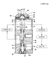
- An expansion valve 1 shown in FIG. 1 is used in a refrigeration cycle of an air conditioner such as an automobile, and is disposed inside a prismatic valve body 20 made of aluminum or the like from a refrigerant outlet of a condenser via a receiver.
- a valve chamber 32 and an orifice 33 for adiabatically expanding the refrigerant are formed.
- a spherical valve body 34 that opens and closes the orifice 33 in contact with and separates from a valve seat formed on the inlet side of the orifice 33 is disposed, and the valve body 34 is supported by a support member 35.
- the support member 35 is urged in a direction approaching the valve seat by an urging force of an urging means 36 such as a compression coil spring disposed between the support member 35 and a plug 37 screwed to the lower end of the valve chamber 32.
- a seal member such as an O-ring 37 a is interposed between the plug 37 and the valve body 20.
- valve body 20 is formed with a through hole 22 that vertically cuts through the partition wall 21 between the first passage 30 and the second passage 31, and an operating rod 38 made of stainless steel or the like is formed in the through hole 22. Is slidably inserted. The lower end portion of the operating rod 38 is in contact with the valve body 34, and the upper end portion of the operating rod 38 is connected to a power element 40 serving as a temperature-sensitive drive unit described later.
- the power element 40 is formed between a diaphragm 41 made of a thin metal plate such as flexible stainless steel, an upper cover 42 and a lower cover 43 that sandwich the periphery thereof, and the diaphragm 41 and the upper cover 42.
- a diaphragm driving medium sealed in the upper pressure chamber 44 and a plug 46 for sealing an opening for injecting the diaphragm driving medium into the upper pressure chamber 44 are provided.
- a lower pressure chamber 45 formed between the diaphragm 41 and the lower cover 43 communicates with the second passage 31 through a through hole 47 formed concentrically with the center line of the orifice 33 in the valve body 20. .
- the refrigerant vapor from the evaporator flows through the second passage 31, and the pressure of the refrigerant acts on the lower pressure chamber 45 through the through hole 47.
- a stopper portion 48 that comes into contact with the lower surface of the diaphragm 41. This stopper portion 48 is supported by the lower cover 43 so as to slide up and down in the lower pressure chamber 45, and an operating rod. 38 is connected to the upper end of 38.
- the refrigerant temperature on the outlet side of the evaporator is transmitted to the upper pressure chamber 44 directly or via the stopper portion 48.
- the pressure of the diaphragm drive medium in the upper pressure chamber 44 changes corresponding to the transmitted temperature and acts on the upper surface of the diaphragm 41.
- the diaphragm 41 is displaced up and down due to the difference between the pressure of the diaphragm driving medium acting on the upper surface of the diaphragm 41 and the refrigerant pressure acting on the lower surface of the diaphragm 41.
- the valve body 34 is moved closer to or away from the valve seat of the orifice 33. As a result, the refrigerant flow rate is controlled.
- the outlet temperature of the evaporator rises, and the pressure of the upper pressure chamber 44 that receives the heat rises. Since it is pushed down, the opening of the orifice 33 increases. As a result, the amount of refrigerant supplied to the evaporator increases, and the temperature of the evaporator decreases. Conversely, when the evaporator thermal load decreases, the opening of the orifice 33 decreases and the amount of refrigerant supplied to the evaporator decreases.
- the upper end of the through hole 22 has a large diameter, and this portion includes an O-ring that seals the periphery of the operating rod 38 in order to ensure airtightness between the first passage 30 and the second passage 31.
- Such a sealing member (not shown) and an anti-vibration spring member 23 that stably supports the operating rod 38 from the surroundings are provided.
- a power element storage chamber 24 is provided at the upper end of the valve body 20.
- the power element housing chamber 24 is formed with a bottom so as to open to the upper end of the valve body 20, and is sealed by a closing member 50 fixed to the upper end of the peripheral wall 26 of the valve body 20.
- the closing member 50 is fixed to the upper end of the peripheral wall 26 by welding or welding in order to eliminate the need for a sealing member for sealing between the valve body 20.
- the lower surface of the closing member 50 is formed in a shape substantially matched to the surface of the upper cover 42 of the power element 40, and a plurality of convex portions 53 are circumferentially spaced at the periphery of the lower surface of the closing member 50. Is provided.
- the convex portion 53 of the closing member 50 comes into contact with the upper cover 42, and the power element 40 is in the power element accommodation chamber 24.
- the bottom wall 27 is pressed and fixed.
- These convex portions 53 serve as a plurality of partial contact portions with respect to the power element 40 of the closing member 50.
- the fixing method of the closing member 50 to the valve body 20 can be, for example, electron beam welding which is a linear heat source and can deepen the penetration.
- electron beam welding By the electron beam welding, the valve main body 20 and the closing member 50 are heated to the melting point or higher to be melt welded.
- the peripheral portion 52 of the closing member 50 corresponding to the peripheral wall 26 of the valve body 20 is irradiated with the electron beam B from the upper side to the lower side, and the irradiation state is maintained.
- the irradiation position is relatively moved by rotating the valve body 20 and the closing member 50, and the peripheral portion 52 of the closing member 50 is continuously welded to the upper surface 26 a of the peripheral wall 26.
- the closing member 50 is securely and airtightly fixed to the valve body 20, and leakage of the refrigerant to which the power element 40 is exposed can be prevented.
- both the power element 40 and the valve body 20 need to be threaded. In the present invention, such threading is not necessary. become. Further, since the space between the closing member 50 and the valve body 20 is sealed, a sealing member such as an O-ring is not necessary. Therefore, manufacturing cost can be reduced.
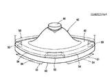
- FIG. 2 is an enlarged cross-sectional view showing a part of the expansion valve shown in FIG. 3 is an enlarged perspective view showing a part of the bottom wall 27 of the power element accommodating chamber 24 shown in FIG. 1, and FIG. 4 is an enlarged perspective view showing the power element 40 of the expansion valve shown in FIG. is there.
- the bottom wall 27 is provided with a plurality of recesses 61 that are radially formed around the central through hole 47 and communicate with the through hole 47.
- a support portion 62 is formed between the adjacent recesses 61, and the lower cover 43 of the power element 40 is received by the bottom wall 27 of the power element accommodation chamber 24 by the plurality of partial support portions 62. Supported.
- the end surface 63 of the recess 61 is an inclined surface between the adjacent support portions 62 and 62, and a gap 64 (see FIG. 4) is formed between the lower cover 43 and the through hole 47 and the power through the gap 64.
- the element storage chamber 24 communicates with the element storage chamber 24. Therefore, the refrigerant flowing through the second passage 31 is introduced into the power element accommodation chamber 24 through the recess 61 as indicated by an arrow in FIG.
- a plurality of recesses 61 are provided in the bottom wall 27 of the power element accommodation chamber 24.
- a recess similar to the recess 61 may be provided on the side facing the bottom wall 27.
- a similar recess can be provided on the side of the lower cover 43 facing the bottom wall 27.
- a member formed in a waveform in the circumferential direction may be interposed between the bottom wall 27 and the lower cover 43 to provide the same effect as the concave portion 61.
- circulates between the closing member 50 and the upper cover 42 is formed by providing a recessed part in the closing member 50 or the upper cover 42. It may be. Further, a member that is corrugated in the circumferential direction is interposed between the upper cover 42 and the closing member 50, thereby forming a gap through which the refrigerant flows between the closing member 50 and the upper cover 42. Good.
- the periphery of the power element 40 is filled with the low-pressure refrigerant introduced from the second passage 31 into the power element accommodating chamber 24, and the power element 40 is less susceptible to the outside air temperature.
- the flow rate of the refrigerant passing through 33 can be controlled with high accuracy.
- the power element storage chamber 24 is provided in a state of being separated upward from the second passage 31, so that the power element 40 does not protrude into the second passage 31 and the inner surface of the second passage 31 is substantially flat. Since the flow of the low-pressure refrigerant flowing through the second passage 31 is not hindered, the pressure loss of the low-pressure refrigerant can be reduced.
- FIG. 5 is a longitudinal sectional view showing another embodiment of the expansion valve according to the present invention
- FIG. 6 is an enlarged sectional view showing a part of the expansion valve shown in FIG.
- the same reference numerals as those used in FIG. 1 are used for the same portions as the elements and portions of the embodiment shown in FIG.
- the closing member 50 is formed so as to be fitted inside a cylindrical peripheral wall 26 formed on the upper surface of the valve body 20.
- laser light is irradiated over the entire circumference from the direction of L 1 or L 2 shown in FIG. 6, and the closing member 50 is fixed to the peripheral wall 26 by welding.
- An annular convex portion 53 formed on the lower surface of the closing member 50 abuts on the upper cover 42 of the power element 40, whereby the power element 40 is pressed and fixed onto the bottom wall 27 of the power element accommodation chamber 24.
- a plurality of concave portions are provided on the lower surface of the convex portion 53 at intervals in the circumferential direction, and a gap 54 is formed between the lower portion and the upper cover 42.
- the lower cover 43 of the power element 40 is formed in a narrow wedge-shaped annular shape, and the inner peripheral portion thereof is opposed to the outer peripheral portion of the stopper portion 48 at a radial interval.
- a plurality of recesses are provided on the lower surface of the lower cover 43 at intervals in the circumferential direction, and a gap 43 a is formed between the lower cover 43 and the bottom wall 27 of the power element storage chamber 24.
- the stopper portion 48 is accommodated in a recess 28 formed in the valve body 20.
- the stopper portion 48 is composed of a large-diameter portion and a small-diameter portion formed on the lower surface thereof.
- the lower surface of the large-diameter portion is provided with a plurality of concave portions at intervals in the circumferential direction.
- a plurality of gaps 48a are formed.
- the low-pressure refrigerant flowing through the second passage 31 flows into the power element accommodation chamber 24 through the through hole 47 and the gap 48a, and flows around the power element 40 through the gaps 43a and 54.
- the stopper portion 48 is positioned downward by the lower cover 43 of the power element 40, whereas in this embodiment, this positioning is performed by the recess 28 formed in the valve body 20. Since it is performed on the bottom surface, the height of the expansion valve can be made smaller than in the embodiment of FIG. In addition, since the lower cover 43 is not sandwiched between the valve body 20 and the stopper portion 48, variations in the thickness of the lower cover 43 do not affect the position of the diaphragm 41. Therefore, since the position of the diaphragm 41 is determined only by the cutting of the valve body 20 and the processing accuracy of the stopper portion 48, variation in performance can be reduced.
- FIG. 7 shows an embodiment in which the valve body and the closing member are made of resin.
- the same reference numerals as those used in FIG. 1 are used for parts equivalent to the elements and parts of the embodiment shown in FIG.
- the closure member 50 can be fixed to the valve body 20 by, for example, ultrasonic welding.
- the upper end of the cylindrical peripheral wall 56 of the valve body 20 is configured in a concentric stepped structure, and the peripheral portion 57 is formed in a stepped structure so that the closing member 50 is fitted into the stepped structure. It is configured.
- a plurality of convex portions 58 are provided in the peripheral edge portion of the lower surface of the closing member 50 at intervals in the circumferential direction, the power element 40 is accommodated in the power element accommodating chamber 24, and the peripheral edge portion of the closing member 50 is defined as the peripheral wall 56. Then, the convex portion 58 of the closing member 50 comes into contact with the upper cover 42, and the power element 40 is pressed and fixed onto the bottom wall 27 of the power element housing chamber 24.
- the ultrasonic wave S is continuously applied in the circumferential direction from above the peripheral portion 57 of the closing member 50, whereby the resin is continuously melted at the fitting portion of the step structure of the closing member 50 and the peripheral wall 56. Done.
- the closing member 50 is securely and airtightly fixed to the valve body 20, and leakage of the refrigerant to which the power element 40 is exposed can be prevented. Also in the present embodiment, the threading of the power element 40 and the valve main body 20 is unnecessary, and the sealing member between the closing member 50 and the valve main body 20 is also unnecessary, so that the manufacturing cost can be reduced.
Landscapes
- Physics & Mathematics (AREA)
- Engineering & Computer Science (AREA)
- Fluid Mechanics (AREA)
- Mechanical Engineering (AREA)
- Thermal Sciences (AREA)
- General Engineering & Computer Science (AREA)
- Temperature-Responsive Valves (AREA)
Abstract
Description
Claims (9)
- コンデンサからエバポレータへ向かう冷媒が通る第1の通路、該第1の通路の上方に設けられエバポレータからコンプレッサへ向かう冷媒が通る第2の通路及び前記第1の通路の途中に設けられたオリフィスを有する弁本体と、前記オリフィスを開閉する弁体と、前記弁本体に摺動自在に支持された作動棒と、該作動棒を介して前記弁体を駆動するパワーエレメントとを備えた膨張弁において、
前記弁本体の上端に開口する有底のパワーエレメント収容室と、前記弁本体の上端に固着され前記パワーエレメントを前記パワーエレメント収容室の底壁との間に挟み込んで固定するとともに前記パワーエレメント収容室の開口を気密状態に密閉する閉鎖部材とを設けたことを特徴とする膨張弁。 - 前記閉鎖部材が溶接又は溶着により前記弁本体に固着されることを特徴とする請求項1記載の膨張弁。
- 前記弁本体と前記閉鎖部材が金属製であり、前記閉鎖部材が電子ビーム溶接又はレーザー溶接により前記弁本体に固着されることを特徴とする請求項2記載の膨張弁。
- 前記弁本体と前記閉鎖部材が合成樹脂製であり、前記閉鎖部材が超音波溶着により前記弁本体に固着されることを特徴とする請求項2記載の膨張弁。
- コンデンサからエバポレータへ向かう冷媒が通る第1の通路、該第1の通路の上方に設けられエバポレータからコンプレッサへ向かう冷媒が通る第2の通路及び前記第1の通路の途中に設けられたオリフィスを有する弁本体と、前記オリフィスを開閉する弁体と、前記弁本体に摺動自在に支持された作動棒と、該作動棒を介して前記弁体を駆動するパワーエレメントとを備えた膨張弁において、
前記第2の通路の上方に前記パワーエレメントを収容する有底のパワーエレメント収容室を設けるとともに、該パワーエレメント収容室と前記第2の通路とを連通させたことを特徴とする膨張弁。 - 前記弁本体に溶接又は溶着により固着される閉鎖部材により前記パワーエレメント収容室の上面が密閉されることを特徴とする請求項5記載の膨張弁。
- 前記弁本体と前記閉鎖部材が金属製であり、前記閉鎖部材が電子ビーム溶接又はレーザー溶接により前記弁本体に固着されることを特徴とする請求項6記載の膨張弁。
- 前記閉鎖部材が前記パワーエレメントを前記パワーエレメント収容室の底壁との間に挟み込んで固定することを特徴とする請求項5又は6記載の膨張弁。
- 前記閉鎖部材を前記弁本体に固着した状態で前記閉鎖部材と前記パワーエレメントとの間及び前記パワーエレメントと前記底壁との間にそれぞれ隙間が形成され、前記第2の通路を流れる低圧冷媒が前記各隙間を介して前記パワーエレメントの周囲に流通するように構成したことを特徴とする請求項8記載の膨張弁。
Priority Applications (2)
| Application Number | Priority Date | Filing Date | Title |
|---|---|---|---|
| CN201180010101.1A CN102762935B (zh) | 2010-03-29 | 2011-03-24 | 膨胀阀 |
| JP2012508244A JP5680062B2 (ja) | 2010-03-29 | 2011-03-24 | 膨張弁 |
Applications Claiming Priority (4)
| Application Number | Priority Date | Filing Date | Title |
|---|---|---|---|
| JP2010-074537 | 2010-03-29 | ||
| JP2010074537 | 2010-03-29 | ||
| JP2010077177 | 2010-03-30 | ||
| JP2010-077177 | 2010-03-30 |
Publications (1)
| Publication Number | Publication Date |
|---|---|
| WO2011122435A1 true WO2011122435A1 (ja) | 2011-10-06 |
Family
ID=44712144
Family Applications (1)
| Application Number | Title | Priority Date | Filing Date |
|---|---|---|---|
| PCT/JP2011/057150 Ceased WO2011122435A1 (ja) | 2010-03-29 | 2011-03-24 | 膨張弁 |
Country Status (3)
| Country | Link |
|---|---|
| JP (1) | JP5680062B2 (ja) |
| CN (1) | CN102762935B (ja) |
| WO (1) | WO2011122435A1 (ja) |
Cited By (9)
| Publication number | Priority date | Publication date | Assignee | Title |
|---|---|---|---|---|
| JP2013195003A (ja) * | 2012-03-21 | 2013-09-30 | Fuji Koki Corp | 膨張弁 |
| WO2015037207A1 (ja) * | 2013-09-11 | 2015-03-19 | 株式会社デンソー | 膨張弁 |
| WO2015072088A1 (ja) * | 2013-11-14 | 2015-05-21 | 株式会社デンソー | 膨脹弁 |
| JP2016196982A (ja) * | 2015-04-03 | 2016-11-24 | 株式会社不二工機 | カシメ固定型パワーエレメント及びこれを用いた膨張弁 |
| JP2017044374A (ja) * | 2015-08-25 | 2017-03-02 | 株式会社デンソー | エジェクタ |
| JP2017058112A (ja) * | 2015-09-18 | 2017-03-23 | 株式会社不二工機 | 膨張弁 |
| JP2017172846A (ja) * | 2016-03-23 | 2017-09-28 | 株式会社テージーケー | 膨張弁 |
| US10240831B2 (en) | 2013-09-11 | 2019-03-26 | Denso Corporation | Expansion valve |
| JP2019066064A (ja) * | 2017-09-29 | 2019-04-25 | 株式会社不二工機 | 膨張弁 |
Families Citing this family (3)
| Publication number | Priority date | Publication date | Assignee | Title |
|---|---|---|---|---|
| KR102237210B1 (ko) * | 2017-04-13 | 2021-04-07 | 쯔지앙 산후아 오토모티브 컴포넌츠 컴퍼니 리미티드 | 열 팽창 밸브 |
| JP7134146B2 (ja) * | 2019-07-26 | 2022-09-09 | 株式会社鷺宮製作所 | 膨張弁及び冷凍サイクルシステム |
| JP7182283B2 (ja) * | 2019-11-25 | 2022-12-02 | 株式会社不二工機 | パワーエレメント及びこれを用いた膨張弁 |
Citations (7)
| Publication number | Priority date | Publication date | Assignee | Title |
|---|---|---|---|---|
| JPS50121852A (ja) * | 1974-03-13 | 1975-09-25 | ||
| JP2000220917A (ja) * | 1999-01-28 | 2000-08-08 | Tgk Co Ltd | 過冷却度制御式膨張弁 |
| JP2002195698A (ja) * | 2000-10-17 | 2002-07-10 | Denso Corp | ヒートポンプ用制御弁 |
| JP2004028491A (ja) * | 2002-06-27 | 2004-01-29 | Fuji Koki Corp | 膨張弁 |
| JP2008057949A (ja) * | 2006-05-18 | 2008-03-13 | Tgk Co Ltd | 膨張弁の装着構造 |
| JP2009180419A (ja) * | 2008-01-30 | 2009-08-13 | Tgk Co Ltd | 膨張弁 |
| JP2009222144A (ja) * | 2008-03-17 | 2009-10-01 | Tgk Co Ltd | 膨張弁 |
Family Cites Families (2)
| Publication number | Priority date | Publication date | Assignee | Title |
|---|---|---|---|---|
| JPH10253199A (ja) * | 1997-03-11 | 1998-09-25 | Fuji Koki Corp | 温度式膨張弁 |
| CN101074809A (zh) * | 2006-05-18 | 2007-11-21 | 株式会社Tgk | 膨胀阀的安装结构 |
-
2011
- 2011-03-24 WO PCT/JP2011/057150 patent/WO2011122435A1/ja not_active Ceased
- 2011-03-24 JP JP2012508244A patent/JP5680062B2/ja active Active
- 2011-03-24 CN CN201180010101.1A patent/CN102762935B/zh active Active
Patent Citations (7)
| Publication number | Priority date | Publication date | Assignee | Title |
|---|---|---|---|---|
| JPS50121852A (ja) * | 1974-03-13 | 1975-09-25 | ||
| JP2000220917A (ja) * | 1999-01-28 | 2000-08-08 | Tgk Co Ltd | 過冷却度制御式膨張弁 |
| JP2002195698A (ja) * | 2000-10-17 | 2002-07-10 | Denso Corp | ヒートポンプ用制御弁 |
| JP2004028491A (ja) * | 2002-06-27 | 2004-01-29 | Fuji Koki Corp | 膨張弁 |
| JP2008057949A (ja) * | 2006-05-18 | 2008-03-13 | Tgk Co Ltd | 膨張弁の装着構造 |
| JP2009180419A (ja) * | 2008-01-30 | 2009-08-13 | Tgk Co Ltd | 膨張弁 |
| JP2009222144A (ja) * | 2008-03-17 | 2009-10-01 | Tgk Co Ltd | 膨張弁 |
Cited By (12)
| Publication number | Priority date | Publication date | Assignee | Title |
|---|---|---|---|---|
| JP2013195003A (ja) * | 2012-03-21 | 2013-09-30 | Fuji Koki Corp | 膨張弁 |
| WO2015037207A1 (ja) * | 2013-09-11 | 2015-03-19 | 株式会社デンソー | 膨張弁 |
| JP2015055388A (ja) * | 2013-09-11 | 2015-03-23 | 株式会社デンソー | 膨張弁 |
| US10113779B2 (en) | 2013-09-11 | 2018-10-30 | Denso Corporation | Expansion valve |
| US10240831B2 (en) | 2013-09-11 | 2019-03-26 | Denso Corporation | Expansion valve |
| WO2015072088A1 (ja) * | 2013-11-14 | 2015-05-21 | 株式会社デンソー | 膨脹弁 |
| JP2016196982A (ja) * | 2015-04-03 | 2016-11-24 | 株式会社不二工機 | カシメ固定型パワーエレメント及びこれを用いた膨張弁 |
| US10436484B2 (en) | 2015-04-03 | 2019-10-08 | Fujikoki Corporation | Caulking fixation type power element and expansion valve using the same |
| JP2017044374A (ja) * | 2015-08-25 | 2017-03-02 | 株式会社デンソー | エジェクタ |
| JP2017058112A (ja) * | 2015-09-18 | 2017-03-23 | 株式会社不二工機 | 膨張弁 |
| JP2017172846A (ja) * | 2016-03-23 | 2017-09-28 | 株式会社テージーケー | 膨張弁 |
| JP2019066064A (ja) * | 2017-09-29 | 2019-04-25 | 株式会社不二工機 | 膨張弁 |
Also Published As
| Publication number | Publication date |
|---|---|
| CN102762935A (zh) | 2012-10-31 |
| CN102762935B (zh) | 2015-12-09 |
| JP5680062B2 (ja) | 2015-03-04 |
| JPWO2011122435A1 (ja) | 2013-07-08 |
Similar Documents
| Publication | Publication Date | Title |
|---|---|---|
| JP5680062B2 (ja) | 膨張弁 | |
| JPH10170106A (ja) | 膨張弁 | |
| EP2503267B1 (en) | Expansion valve | |
| JP7026979B2 (ja) | 膨張弁 | |
| JPH10253199A (ja) | 温度式膨張弁 | |
| CN102759234B (zh) | 热力膨胀阀 | |
| JP2005164208A (ja) | 膨張弁 | |
| JP2002054861A (ja) | 温度式膨張弁 | |
| JP2002054860A (ja) | 温度式膨張弁 | |
| CN108489161B (zh) | 热力膨胀阀 | |
| WO2019181409A1 (ja) | パワーエレメントおよびそれを有する膨張弁 | |
| JP6447906B2 (ja) | 膨張弁 | |
| JP2018004234A (ja) | 膨張弁 | |
| CN102913656B (zh) | 密封构造及温度膨胀阀 | |
| CN102759235B (zh) | 热力膨胀阀 | |
| JP4047088B2 (ja) | 膨張弁 | |
| JP2004028491A (ja) | 膨張弁 | |
| JP2000304381A (ja) | 温度膨張弁 | |
| JP3942848B2 (ja) | 膨張弁ユニット | |
| JP7390699B2 (ja) | 膨張弁 | |
| JP7519687B2 (ja) | 配管の継手 | |
| JP7051091B2 (ja) | 膨張弁 | |
| JP7249301B2 (ja) | 調整ねじ機構の固定構造及び弁装置並びに冷凍サイクルシステム | |
| JP7418015B2 (ja) | パワーエレメントの製造方法、パワーエレメント及びそれを用いた膨張弁 | |
| JP2009227027A (ja) | 車両用防水構造 |
Legal Events
| Date | Code | Title | Description |
|---|---|---|---|
| WWE | Wipo information: entry into national phase |
Ref document number: 201180010101.1 Country of ref document: CN |
|
| 121 | Ep: the epo has been informed by wipo that ep was designated in this application |
Ref document number: 11762666 Country of ref document: EP Kind code of ref document: A1 |
|
| WWE | Wipo information: entry into national phase |
Ref document number: 2012508244 Country of ref document: JP |
|
| NENP | Non-entry into the national phase |
Ref country code: DE |
|
| 122 | Ep: pct application non-entry in european phase |
Ref document number: 11762666 Country of ref document: EP Kind code of ref document: A1 |