WO2011121839A1 - 電磁式燃料噴射弁及びその製造方法 - Google Patents
電磁式燃料噴射弁及びその製造方法 Download PDFInfo
- Publication number
- WO2011121839A1 WO2011121839A1 PCT/JP2010/070568 JP2010070568W WO2011121839A1 WO 2011121839 A1 WO2011121839 A1 WO 2011121839A1 JP 2010070568 W JP2010070568 W JP 2010070568W WO 2011121839 A1 WO2011121839 A1 WO 2011121839A1
- Authority
- WO
- WIPO (PCT)
- Prior art keywords
- coil
- cylindrical body
- valve
- magnetic
- fuel injection
- Prior art date
- Legal status (The legal status is an assumption and is not a legal conclusion. Google has not performed a legal analysis and makes no representation as to the accuracy of the status listed.)
- Ceased
Links
Images

Classifications
-
- F—MECHANICAL ENGINEERING; LIGHTING; HEATING; WEAPONS; BLASTING
- F02—COMBUSTION ENGINES; HOT-GAS OR COMBUSTION-PRODUCT ENGINE PLANTS
- F02M—SUPPLYING COMBUSTION ENGINES IN GENERAL WITH COMBUSTIBLE MIXTURES OR CONSTITUENTS THEREOF
- F02M51/00—Fuel-injection apparatus characterised by being operated electrically
- F02M51/06—Injectors peculiar thereto with means directly operating the valve needle
- F02M51/061—Injectors peculiar thereto with means directly operating the valve needle using electromagnetic operating means
- F02M51/0625—Injectors peculiar thereto with means directly operating the valve needle using electromagnetic operating means characterised by arrangement of mobile armatures
- F02M51/0664—Injectors peculiar thereto with means directly operating the valve needle using electromagnetic operating means characterised by arrangement of mobile armatures having a cylindrically or partly cylindrically shaped armature, e.g. entering the winding; having a plate-shaped or undulated armature entering the winding
- F02M51/0671—Injectors peculiar thereto with means directly operating the valve needle using electromagnetic operating means characterised by arrangement of mobile armatures having a cylindrically or partly cylindrically shaped armature, e.g. entering the winding; having a plate-shaped or undulated armature entering the winding the armature having an elongated valve body attached thereto
- F02M51/0675—Injectors peculiar thereto with means directly operating the valve needle using electromagnetic operating means characterised by arrangement of mobile armatures having a cylindrically or partly cylindrically shaped armature, e.g. entering the winding; having a plate-shaped or undulated armature entering the winding the armature having an elongated valve body attached thereto the valve body having cylindrical guiding or metering portions, e.g. with fuel passages
-
- F—MECHANICAL ENGINEERING; LIGHTING; HEATING; WEAPONS; BLASTING
- F02—COMBUSTION ENGINES; HOT-GAS OR COMBUSTION-PRODUCT ENGINE PLANTS
- F02M—SUPPLYING COMBUSTION ENGINES IN GENERAL WITH COMBUSTIBLE MIXTURES OR CONSTITUENTS THEREOF
- F02M61/00—Fuel-injectors not provided for in groups F02M39/00 - F02M57/00 or F02M67/00
- F02M61/04—Fuel-injectors not provided for in groups F02M39/00 - F02M57/00 or F02M67/00 having valves, e.g. having a plurality of valves in series
- F02M61/10—Other injectors with elongated valve bodies, i.e. of needle-valve type
- F02M61/12—Other injectors with elongated valve bodies, i.e. of needle-valve type characterised by the provision of guiding or centring means for valve bodies
-
- F—MECHANICAL ENGINEERING; LIGHTING; HEATING; WEAPONS; BLASTING
- F02—COMBUSTION ENGINES; HOT-GAS OR COMBUSTION-PRODUCT ENGINE PLANTS
- F02M—SUPPLYING COMBUSTION ENGINES IN GENERAL WITH COMBUSTIBLE MIXTURES OR CONSTITUENTS THEREOF
- F02M61/00—Fuel-injectors not provided for in groups F02M39/00 - F02M57/00 or F02M67/00
- F02M61/16—Details not provided for in, or of interest apart from, the apparatus of groups F02M61/02 - F02M61/14
- F02M61/168—Assembling; Disassembling; Manufacturing; Adjusting
-
- F—MECHANICAL ENGINEERING; LIGHTING; HEATING; WEAPONS; BLASTING
- F02—COMBUSTION ENGINES; HOT-GAS OR COMBUSTION-PRODUCT ENGINE PLANTS
- F02M—SUPPLYING COMBUSTION ENGINES IN GENERAL WITH COMBUSTIBLE MIXTURES OR CONSTITUENTS THEREOF
- F02M2200/00—Details of fuel-injection apparatus, not otherwise provided for
- F02M2200/08—Fuel-injection apparatus having special means for influencing magnetic flux, e.g. for shielding or guiding magnetic flux
-
- F—MECHANICAL ENGINEERING; LIGHTING; HEATING; WEAPONS; BLASTING
- F02—COMBUSTION ENGINES; HOT-GAS OR COMBUSTION-PRODUCT ENGINE PLANTS
- F02M—SUPPLYING COMBUSTION ENGINES IN GENERAL WITH COMBUSTIBLE MIXTURES OR CONSTITUENTS THEREOF
- F02M2200/00—Details of fuel-injection apparatus, not otherwise provided for
- F02M2200/80—Fuel injection apparatus manufacture, repair or assembly
- F02M2200/8046—Fuel injection apparatus manufacture, repair or assembly the manufacture involving injection moulding, e.g. of plastic or metal
-
- F—MECHANICAL ENGINEERING; LIGHTING; HEATING; WEAPONS; BLASTING
- F02—COMBUSTION ENGINES; HOT-GAS OR COMBUSTION-PRODUCT ENGINE PLANTS
- F02M—SUPPLYING COMBUSTION ENGINES IN GENERAL WITH COMBUSTIBLE MIXTURES OR CONSTITUENTS THEREOF
- F02M2200/00—Details of fuel-injection apparatus, not otherwise provided for
- F02M2200/80—Fuel injection apparatus manufacture, repair or assembly
- F02M2200/8061—Fuel injection apparatus manufacture, repair or assembly involving press-fit, i.e. interference or friction fit
-
- F—MECHANICAL ENGINEERING; LIGHTING; HEATING; WEAPONS; BLASTING
- F02—COMBUSTION ENGINES; HOT-GAS OR COMBUSTION-PRODUCT ENGINE PLANTS
- F02M—SUPPLYING COMBUSTION ENGINES IN GENERAL WITH COMBUSTIBLE MIXTURES OR CONSTITUENTS THEREOF
- F02M2200/00—Details of fuel-injection apparatus, not otherwise provided for
- F02M2200/80—Fuel injection apparatus manufacture, repair or assembly
- F02M2200/8084—Fuel injection apparatus manufacture, repair or assembly involving welding or soldering
-
- F—MECHANICAL ENGINEERING; LIGHTING; HEATING; WEAPONS; BLASTING
- F02—COMBUSTION ENGINES; HOT-GAS OR COMBUSTION-PRODUCT ENGINE PLANTS
- F02M—SUPPLYING COMBUSTION ENGINES IN GENERAL WITH COMBUSTIBLE MIXTURES OR CONSTITUENTS THEREOF
- F02M2200/00—Details of fuel-injection apparatus, not otherwise provided for
- F02M2200/80—Fuel injection apparatus manufacture, repair or assembly
- F02M2200/8092—Fuel injection apparatus manufacture, repair or assembly adjusting or calibration
Definitions
- the present invention relates to an electromagnetic fuel injection valve mainly used for a fuel supply system of an internal combustion engine, and in particular, a valve seat member having a valve hole from the front end to the rear end of the fuel injection valve, a magnetic cylinder, and a nonmagnetic A cylinder housing, a fixed core, and a fuel inlet cylinder are sequentially connected to each other, a valve housing having a fuel flow path inside, a coil disposed on the outer periphery of the valve housing, and the coil is accommodated, and the front end is welded.
- a coil housing fixed to the outer periphery of the magnetic cylinder and magnetically connecting the magnetic cylinder and the fixed core; and a front end of the fixed core slidably fitted to the inner peripheral surface of the magnetic cylinder
- a valve assembly that opens and closes the valve hole when the fixed core is demagnetized and excited, and includes a fixed core, a movable core, a magnetic cylinder, and a coil housing.
- the inner peripheral surface of the magnetic cylinder of such an electromagnetic fuel injection valve slidably supports the movable core of the valve assembly.
- the front end of the coil housing is In order to avoid the occurrence of distortion on the inner peripheral surface of the magnetic cylinder due to the welding heat during welding to the outer peripheral surface of the magnetic cylinder, the connecting end surface between the non-magnetic cylinder and the magnetic cylinder is connected to the front end of the coil.
- the sliding part of the movable core on the inner circumferential surface of the magnetic cylinder is arranged rearward from the surface so as to be moved backward from the welded part at the front end of the coil housing.
- An object of the present invention is to provide an electromagnetic fuel injection valve and a method for manufacturing the same.
- the present invention provides a valve seat member having a valve hole, a magnetic cylinder, a nonmagnetic cylinder, a fixed core, and a fuel inlet cylinder from the front end to the rear end of the electromagnetic fuel injection valve.
- a valve housing that is successively connected and has an internal fuel flow path, a coil that is disposed on the outer periphery of the valve housing, and that accommodates the coil, and the front end is fixed to the outer periphery of the magnetic cylindrical body by welding.
- a coil housing that magnetically connects between the magnetic cylinder and the fixed core; and a movable core that is slidably fitted to the inner peripheral surface of the magnetic cylinder and is opposed to the suction surface at the front end of the fixed core.
- a valve assembly that opens and closes the valve hole in accordance with demagnetization and excitation of the fixed core, and the fixed core, the movable core, the magnetic cylindrical body, and the coil housing, when the coil is energized, Magnet for exciting
- the magnetic cylinder and the non-magnetic cylinder are arranged so that a boundary surface between the two and the non-magnetic cylinder protrudes forward from the coil, and the inner end in the radial direction of the front end of the coil housing.
- a first feature is that a journal portion that is slidably supported on the inner peripheral surface of the magnetic cylindrical body at one side is formed on the movable core.
- the present invention has a second feature in that the fixed core is arranged so that the suction surface at the front end thereof protrudes forward from the coil.
- the present invention provides the electromagnetic fuel injection valve according to the first or second feature, wherein the front end of the coil housing is fixed to the outer peripheral surface of the magnetic cylindrical body by welding,
- a third feature is that the peripheral surface and the suction surface of the fixed core are finished by cutting.
- the boundary surface between the magnetic cylindrical body and the nonmagnetic cylindrical body is disposed in front of the coil, and the magnetic cylindrical body is located at a radially inward position of the front end portion of the coil housing.
- the suction surface at the front end of the fixed core is disposed in front of the front end surface of the coil, the magnetic field in the section from the front end of the coil housing to the fixed core through the movable core is arranged.
- the path length is further shortened and the magnetic path resistance is further reduced to improve the valve opening responsiveness of the valve assembly.
- the residual magnetism of the movable core is quickly lost.
- the three-dimensional valve closing response can also be improved.
- the suction surface at the front end of the fixed core comes forward from the front end surface of the coil, the axial length of the valve assembly is reduced and its weight is reduced. Can be reduced.
- the front end of the coil housing is fixed to the outer peripheral surface of the magnetic cylinder by welding, and then the inner peripheral surface of the magnetic cylinder and the suction surface of the fixed core are finished by cutting.
- the fixed portion by welding between the front end portion of the coil housing and the magnetic cylindrical body approaches the circumferential surface of the magnetic cylindrical body or the attracting surface of the fixed core, thereby Even if distortion occurs on the peripheral surface of the cylindrical body and the suction surface of the fixed core due to welding heat, the distortion can be removed by the above-described cutting process, thus ensuring accurate operation of the valve assembly and high performance electromagnetic A fuel injection valve can be obtained.
- FIG. 1 is a longitudinal sectional view of an electromagnetic fuel injection valve according to the present invention.
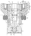
- FIG. 2 is an enlarged view of part 2 of FIG.
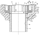
- FIG. 3 is an explanatory diagram of a cutting process during the manufacturing process of the electromagnetic fuel injection valve.
- a valve housing 2 of an electromagnetic fuel injection valve (hereinafter simply referred to as a fuel injection valve) I for an engine is fitted to a cylindrical valve seat member 3 and a rear end portion of the valve seat member 3.
- a magnetic cylinder 4 that is liquid-tightly welded, a non-magnetic cylinder 6 that is abutted against the rear end of the magnetic cylinder 4 and is liquid-tightly welded, and an inner peripheral surface of the non-magnetic cylinder 6
- a cylindrical fixed core 5 fitted with a front end portion and welded in a liquid-tight manner, and a fuel inlet cylinder 9 integrally connected to the rear end of the fixed core 5 with the same material.
- the valve seat member 3 includes a valve hole 7 that opens to the front end surface thereof, a conical valve seat 8 that is connected to the inner end of the valve hole 7, and a large-diameter portion of the valve seat 8. And a cylindrical large-diameter hole 17 having a diameter larger than that of the valve-body guide 15 and connected to the rear end of the valve-body guide 15 via a tapered hole 16.
- a steel plate injector plate 10 having a plurality of fuel injection holes 11 communicating with the valve hole 7 is welded to the front end face of the valve seat member 3 in a liquid-tight manner.
- a portion that does not fit with the fixed core 5 remains at the front end portion of the nonmagnetic cylindrical body 6, and the valve assembly V is accommodated in the valve housing 2 extending from the portion to the valve seat member 3.
- the valve assembly V is welded to the movable core 12 opposed to the suction surface 5a at the front end of the fixed core 5, the valve rod 13 protruding integrally with the front end of the movable core 12, and the valve rod 13.
- the basic shape slidably supported by the guide 15 so as to open and close the valve hole 7 in cooperation with the valve seat 8 is composed of a spherical valve body 14.
- An annular journal portion 12 a that is slidably supported on the inner peripheral surface 4 a of the magnetic cylindrical body 4 is formed.
- valve assembly V is slidably supported on the valve housing 2 at two points of the valve body 14 and the journal portion 12a that are largely separated from each other, so that the opening / closing posture of the valve assembly V is stabilized.
- a plurality of flat flow path portions 18, 18... Permitting the passage of fuel are formed at equal intervals.
- the first fixed hole 5 is provided with a first vertical hole 19 connected to the hollow portion of the fuel inlet tube 9.
- the valve assembly V has a second vertical hole 20 that starts from the rear end surface of the movable core 12 and ends at the middle of the valve rod 13, and the second vertical hole 20 is opened to the large-diameter hole 17 of the valve seat member 3. Lateral holes 21 are provided.
- an annular spring seat 24 facing the fixed core 5 is formed in the middle of the second vertical hole 20.
- a slotted pipe retainer 23 is press-fitted into the first vertical hole 19 of the fixed core 5, and the movable core 12 is urged toward the valve closing side of the valve body 14 between the retainer 23 and the spring seat 24.
- the valve spring 22 is contracted. At that time, the set load of the valve spring 22 is adjusted by the fitting depth of the retainer 23 into the first vertical hole 19.
- the movable core 12 is embedded with a ring-shaped stopper member 27 made of a nonmagnetic material that slightly protrudes from the rear end surface thereof and faces the suction surface 5 a of the fixed core 5.
- the stopper member 27 has a predetermined gap between the opposed end surfaces of the fixed core 5 and the movable core 12 by the stopper member 27 coming into contact with the suction surface 5a of the fixed core 5 when the fixed and movable cores 5 and 12 are attracted to each other. Is to remain.
- a coil assembly 28 is fitted to the outer periphery of the soot valve housing 2 so as to correspond to the fixed core 5 and the movable core 12.
- the coil assembly 28 includes a bobbin 29 fitted to the outer peripheral surface from the rear end portion of the magnetic cylindrical body 4 to the fixed core 5, and a coil 30 wound around the bobbin 29.
- a base end portion of the coupler terminal 33 protruding to one side is held, and the terminal of the coil 30 is connected to the coupler terminal 33.
- a synthetic resin primary coating layer 34 covering the outer periphery of the coil assembly 28 is molded so as to embed the coil 30.
- a coupler 35 that accommodates and holds the coupler terminal 33 and protrudes to one side of the coil assembly 28 is integrally formed with the primary coating layer 34.
- a magnetic coil housing 31 for accommodating and holding the coil assembly 28 is attached to the valve housing 2.
- the coil housing 31 includes a body portion 31a that surrounds the coil assembly 28, and a pair of front and rear end walls 31b that bend radially inward from both ends of the body portion 31a to support both front and rear end surfaces of the coil assembly 28. , 31b 'and a pair of front and rear connecting cylindrical portions 31c, 31c' which protrude axially outward from both end walls 31b, 31b 'and fit to the outer peripheral surfaces of the magnetic cylindrical body 4 and the fixed core 5.
- the distal end portions of the connecting tube portions 31c and 31c ′ are cut off at the outer periphery into thin portions 31d. These thin portions 31d are fixed to the outer peripheral surfaces of the magnetic cylindrical body 4 and the fixed core 5 by laser welding 32. Laser welding at the thin portion 31d requires relatively little heat input, and the thermal distortion of the magnetic cylindrical body 4 and the fixed core 5 can be kept small.
- the coil housing 31, the magnetic cylindrical body 4, the movable core 12, and the fixed core 5 form a magnetic path 39 for exciting the fixed core 5 when the coil 30 is energized.
- the magnetic cylinder 4 and the non-magnetic cylinder 6 are arranged such that the boundary surface B between them 4 and 6 comes out of the coil 30 by a distance S1, and the fixed core 5 is attracted to the front end thereof.
- the surface 5a is disposed so as to protrude a distance S2 ahead of the coil 30.
- journal portion 12a on the outer periphery of the movable core 12 that is slidably supported on the inner peripheral surface of the magnetic cylindrical body 4 is disposed at the front end portion of the coil housing 31, that is, the radially inner position of the connecting cylinder portion 31c. Is done.
- the outer periphery of the magnetic cylinder 4 extends from the rear half of the magnetic cylinder 4 to the rear end of the fixed core 5 and is made of a synthetic resin that embeds the roots of the coil assembly 28, the coil housing 31, and the coupler 35.
- the secondary coating layer 36 is formed by molding.
- An annular seal groove 41 for mounting a seal member 40 such as an O-ring is formed on the outer periphery of the rear end portion of the fuel inlet tube 9.
- the front end wall of the seal groove 41 is constituted by a flange 42 a at the rear end of a collar 42 made of synthetic resin that is press-fitted into the front outer peripheral surface of the fuel inlet cylinder 9, and the rear end wall is the inlet of the fuel inlet cylinder 9. It is comprised by the attachment flange 43a of the fuel filter 43 press-fit in. Therefore, when the seal member 40 is mounted, the collar 42 is press-fitted into the front outer peripheral surface of the fuel inlet tube 9 and then the seal member 40 is fitted to the rear outer peripheral surface of the fuel inlet tube 9.
- the mounting flange 43 a is press-fitted into the inlet of the fuel inlet cylinder 9. By doing so, it is possible to mount the seal member 40 in the seal groove 41 without forcibly expanding the seal member 40.
- a seal member 44 that is in close contact with the front end surface of the secondary coating layer 36 is attached to the outer periphery of the magnetic cylindrical body 4.
- High-pressure fuel pumped from a fuel pump (not shown) to the fuel inlet cylinder 9 is filtered by the fuel filter 43, and then the inside of the valve housing 2, that is, the hollow portion of the fuel inlet cylinder 9, the first vertical hole 19 of the fixed core 5, The second vertical hole 20 and the horizontal hole 21 of the valve assembly V, the large-diameter hole 17, the tapered hole 16 and the valve body guide hole 15 of the valve seat member 3 are filled.
- the coil 30 is demagnetized, the valve assembly V is pressed forward by the urging force of the valve spring 22, and the valve body 14 is seated on the valve seat 8.
- the magnetic flux generated by the coil 30 sequentially runs on the magnetic path 39, that is, the coil housing 31, the magnetic cylindrical body 4, the movable core 12 and the fixed core 5, and is generated by the magnetic force generated between the cores 5 and 12.
- the movable core 12 is attracted to the fixed core 5 against the set load of the valve spring 22 by the suction force, and the valve body 14 is separated from the valve seat 8, so that the valve hole 7 is opened and the valve seat member 3
- High-pressure fuel exits the valve hole 7 and is injected from the fuel injection hole 11 of the injector plate 10 into a throttle body (not shown) equipped with the fuel injection valve I or an intake passage of the engine.
- the magnetic cylindrical body 4 and the nonmagnetic cylindrical body 6 are arranged so that the boundary surface B between the both 4 and 6 protrudes forward from the coil 30.
- the magnetic cylindrical body 4 Since the journal portion 12a on the outer periphery of the movable core 12 that is slidably supported on the inner peripheral surface of the coil housing 31 is disposed at the radially inward position of the connecting cylinder portion 31c at the front end portion of the coil housing 31, the front end of the coil housing 31 is provided.
- the length of the magnetic path in the section extending from the journal portion 12a of the movable core 12 to the fixed core 5 is shorter than the conventional one, and accordingly the magnetic path resistance in the section is reduced.
- the fixed core 5 has the front end attracting surface 5 a disposed in front of the coil 30, so that the magnetic path length in the section from the front end of the coil housing 31 to the fixed core 5 through the movable core 12. Not only improves the valve opening response of the valve assembly V by further reducing the magnetic path resistance, but also the loss of the residual magnetism of the movable core 12 is accelerated when the coil 30 is energized. The valve closing response of the assembly V can also be improved.
- the suction surface 5a at the front end of the fixed core 5 protrudes ahead of the coil 30, the axial length of the valve assembly V is reduced from the conventional one, and the weight thereof is reduced. Is less seated on the valve seat 8, and the operating noise generated due to the stopper member 27 of the movable core 12 abutting against the suction surface 5a of the fixed core 5 is reduced from the conventional one.
- the front end of the coil housing 31 is fixed to the outer peripheral surface of the magnetic cylindrical body 4 by welding 32, and then the inner peripheral surface 4a of the magnetic cylindrical body 4 and the suction surface of the fixed core 5 are used. Since 5a is finished by cutting, according to the above-described configuration, the fixed portion by welding 32 between the front end portion of the coil housing 31 and the magnetic cylindrical body 4 is the inner peripheral surface 4a of the magnetic cylindrical body 4 and the suction surface of the fixed core 5. By approaching 5a, even if distortion occurs on the inner peripheral surface 4a of the magnetic cylindrical body 4 and the suction surface 5a of the fixed core 5 due to welding heat, the distortion can be removed by the cutting process.
- valve assembly V is inserted into the magnetic cylinder 4, and the valve seat member 3 is fitted to the front end of the magnetic cylinder 4 and welded.
- accurate operation of the valve assembly V can be ensured, and a high-performance fuel injection valve I can be obtained.
Landscapes
- Engineering & Computer Science (AREA)
- Chemical & Material Sciences (AREA)
- Combustion & Propulsion (AREA)
- Mechanical Engineering (AREA)
- General Engineering & Computer Science (AREA)
- Manufacturing & Machinery (AREA)
- Physics & Mathematics (AREA)
- Electromagnetism (AREA)
- Fuel-Injection Apparatus (AREA)
- Magnetically Actuated Valves (AREA)
Abstract
Description
I・・・・・電磁式燃料噴射弁
V・・・・・弁組立体
2・・・・・弁ハウジング
3・・・・・弁座部材
4・・・・・磁性円筒体
4a・・・・磁性円筒体の内周面
5・・・・・固定コア
5a・・・・固定コアの吸引面
6・・・・・非磁性円筒体
7・・・・・弁孔
12・・・・可動コア
12a・・・ジャーナル部
30・・・・コイル
31・・・・コイルハウジング
31c・・・コイルハウジングの前端部(連結筒部)
32・・・・溶接
39・・・・磁路
Claims (3)
- 電磁式燃料噴射弁(I)の前端から後端に向けて,弁孔(7)を有する弁座部材(3),磁性円筒体(4),非磁性円筒体(6),固定コア(5)及び燃料入口筒(9)を順次連ねてなり内部を燃料流路とする弁ハウジング(2)と,この弁ハウジング(2)の外周に配設されるコイル(30)と,このコイル(30)を収容すると共に,前端部(31c)を溶接(32)により前記磁性円筒体(4)の外周に固着して前記磁性円筒体(4)及び固定コア(5)間を磁気的に接続するコイルハウジング(31)と,前記磁性円筒体(4)の内周面(4a)に摺動自在に嵌合されて前記固定コア(5)の前端の吸引面(5a)に対置される可動コア(12)を有し,前記固定コア(5)の消磁及び励磁に伴ない前記弁孔(7)を開閉する弁組立体(V)とを備え,前記固定コア(5),可動コア(12),磁性円筒体(4)及びコイルハウジング(31)により,前記コイル(30)の通電時,前記固定コア(5)を励磁するための磁路(39)を形成する電磁式燃料噴射弁において,
前記磁性円筒体(4)及び非磁性円筒体(6)を,その両者間の境界面(B)が前記コイル(30)の前端面より前方に出るように配置すると共に,前記コイルハウジング(31)の前端部(31c)の半径方向内方位置で前記磁性円筒体(4)の内周面に摺動自在に支承されるジャーナル部(12a)を前記可動コア(12)に形成したことを特徴とする電磁式燃料噴射弁。 - 請求項1記載の電磁式燃料噴射弁において,
前記固定コア(5)を,その前端の吸引面(5a)が前記コイル(30)より前方に出るように配置したことを特徴とする電磁式燃料噴射弁。 - 請求項1又は2記載の電磁式燃料噴射弁を製造するに当たり,
前記コイルハウジング(31)の前端部を前記磁性円筒体(4)の外周面に溶接(32)により固着した後,前記磁性円筒体(4)の内周面(4a)及び前記固定コア(5)の吸引面(5a)を切削加工により仕上げることを特徴とする電磁式燃料噴射弁の製造方法。
Priority Applications (2)
| Application Number | Priority Date | Filing Date | Title |
|---|---|---|---|
| BR112012023058A BR112012023058A8 (pt) | 2010-03-29 | 2010-11-18 | válvula de injeção de combustível eletromagnética e método para fabricá-la |
| CN201080065792.0A CN102822498B (zh) | 2010-03-29 | 2010-11-18 | 电磁式燃料喷射阀及其制造方法 |
Applications Claiming Priority (2)
| Application Number | Priority Date | Filing Date | Title |
|---|---|---|---|
| JP2010-075542 | 2010-03-29 | ||
| JP2010075542A JP2011208530A (ja) | 2010-03-29 | 2010-03-29 | 電磁式燃料噴射弁及びその製造方法 |
Publications (1)
| Publication Number | Publication Date |
|---|---|
| WO2011121839A1 true WO2011121839A1 (ja) | 2011-10-06 |
Family
ID=44711613
Family Applications (1)
| Application Number | Title | Priority Date | Filing Date |
|---|---|---|---|
| PCT/JP2010/070568 Ceased WO2011121839A1 (ja) | 2010-03-29 | 2010-11-18 | 電磁式燃料噴射弁及びその製造方法 |
Country Status (4)
| Country | Link |
|---|---|
| JP (1) | JP2011208530A (ja) |
| CN (1) | CN102822498B (ja) |
| BR (1) | BR112012023058A8 (ja) |
| WO (1) | WO2011121839A1 (ja) |
Cited By (5)
| Publication number | Priority date | Publication date | Assignee | Title |
|---|---|---|---|---|
| CN102568741A (zh) * | 2011-12-30 | 2012-07-11 | 成都威特电喷有限责任公司 | 带有衔铁滑枕的快速电磁铁 |
| CN102693813A (zh) * | 2011-12-30 | 2012-09-26 | 成都威特电喷有限责任公司 | 电控燃油喷射快速电磁铁 |
| EP2700806A1 (en) * | 2012-08-23 | 2014-02-26 | Continental Automotive GmbH | Fuel injector, fuel injection assembly and use of a sealing ring |
| EP3064757A1 (en) * | 2015-03-05 | 2016-09-07 | Continental Automotive GmbH | Method for manufacturing an injector for injecting fluid and injector for injecting fluid |
| EP3006721A4 (en) * | 2013-06-06 | 2016-11-23 | Hitachi Automotive Systems Ltd | ELECTROMAGNETIC FUEL INJECTION VALVE |
Families Citing this family (9)
| Publication number | Priority date | Publication date | Assignee | Title |
|---|---|---|---|---|
| US20150014995A1 (en) | 2012-01-17 | 2015-01-15 | Toshihisa Nishioka | Marine power generating system and marine power generating method |
| JP6186126B2 (ja) * | 2013-01-24 | 2017-08-23 | 日立オートモティブシステムズ株式会社 | 燃料噴射装置 |
| CN103233838B (zh) * | 2013-04-23 | 2015-07-15 | 上海理工大学 | 一种电控汽油喷射器及其制造方法 |
| JP6187563B2 (ja) * | 2015-09-28 | 2017-08-30 | 株式会社デンソー | 燃料噴射弁 |
| JP6605371B2 (ja) * | 2016-03-14 | 2019-11-13 | 日立オートモティブシステムズ株式会社 | 電磁ソレノイド及び燃料噴射弁 |
| JP6797697B2 (ja) * | 2017-01-11 | 2020-12-09 | 日立オートモティブシステムズ株式会社 | 燃料噴射弁及び燃料噴射弁の製造方法 |
| CN110651116B (zh) * | 2017-05-23 | 2021-12-24 | 三菱电机株式会社 | 喷射器 |
| JP6773927B1 (ja) * | 2020-01-24 | 2020-10-21 | 株式会社ケーヒン | 電磁式燃料噴射弁 |
| CN117425773A (zh) * | 2021-05-31 | 2024-01-19 | 日立安斯泰莫株式会社 | 电磁式燃料喷射阀 |
Citations (3)
| Publication number | Priority date | Publication date | Assignee | Title |
|---|---|---|---|---|
| JPH05164016A (ja) * | 1991-12-10 | 1993-06-29 | Nippon Injiekuta Kk | 電磁式燃料噴射弁 |
| JP2002081356A (ja) * | 2000-09-06 | 2002-03-22 | Keihin Corp | 電磁式燃料噴射弁 |
| JP2009167901A (ja) * | 2008-01-16 | 2009-07-30 | Aisan Ind Co Ltd | 燃料噴射弁 |
Family Cites Families (6)
| Publication number | Priority date | Publication date | Assignee | Title |
|---|---|---|---|---|
| DE19503821A1 (de) * | 1995-02-06 | 1996-08-08 | Bosch Gmbh Robert | Elektromagnetisch betätigbares Ventil |
| JPH08232801A (ja) * | 1995-02-22 | 1996-09-10 | Nippondenso Co Ltd | 内燃機関用燃料噴射弁 |
| JP2000170620A (ja) * | 1998-12-09 | 2000-06-20 | Keihin Corp | 電磁式燃料噴射弁における磁性体及び非磁性体の組立体,並びに固定コア系組立体の製造方法 |
| US6676044B2 (en) * | 2000-04-07 | 2004-01-13 | Siemens Automotive Corporation | Modular fuel injector and method of assembling the modular fuel injector |
| JP2002004013A (ja) * | 2000-06-16 | 2002-01-09 | Keihin Corp | 電磁弁用コア |
| JP2002310029A (ja) * | 2001-04-10 | 2002-10-23 | Denso Corp | 燃料噴射弁 |
-
2010
- 2010-03-29 JP JP2010075542A patent/JP2011208530A/ja active Pending
- 2010-11-18 WO PCT/JP2010/070568 patent/WO2011121839A1/ja not_active Ceased
- 2010-11-18 CN CN201080065792.0A patent/CN102822498B/zh active Active
- 2010-11-18 BR BR112012023058A patent/BR112012023058A8/pt active Search and Examination
Patent Citations (3)
| Publication number | Priority date | Publication date | Assignee | Title |
|---|---|---|---|---|
| JPH05164016A (ja) * | 1991-12-10 | 1993-06-29 | Nippon Injiekuta Kk | 電磁式燃料噴射弁 |
| JP2002081356A (ja) * | 2000-09-06 | 2002-03-22 | Keihin Corp | 電磁式燃料噴射弁 |
| JP2009167901A (ja) * | 2008-01-16 | 2009-07-30 | Aisan Ind Co Ltd | 燃料噴射弁 |
Cited By (6)
| Publication number | Priority date | Publication date | Assignee | Title |
|---|---|---|---|---|
| CN102568741A (zh) * | 2011-12-30 | 2012-07-11 | 成都威特电喷有限责任公司 | 带有衔铁滑枕的快速电磁铁 |
| CN102693813A (zh) * | 2011-12-30 | 2012-09-26 | 成都威特电喷有限责任公司 | 电控燃油喷射快速电磁铁 |
| EP2700806A1 (en) * | 2012-08-23 | 2014-02-26 | Continental Automotive GmbH | Fuel injector, fuel injection assembly and use of a sealing ring |
| EP3006721A4 (en) * | 2013-06-06 | 2016-11-23 | Hitachi Automotive Systems Ltd | ELECTROMAGNETIC FUEL INJECTION VALVE |
| EP3064757A1 (en) * | 2015-03-05 | 2016-09-07 | Continental Automotive GmbH | Method for manufacturing an injector for injecting fluid and injector for injecting fluid |
| US10323616B2 (en) | 2015-03-05 | 2019-06-18 | Continental Automotive Gmbh | Method of manufacturing an injector for injecting fluid and injector for injecting fluid |
Also Published As
| Publication number | Publication date |
|---|---|
| BR112012023058A2 (pt) | 2016-05-17 |
| JP2011208530A (ja) | 2011-10-20 |
| CN102822498A (zh) | 2012-12-12 |
| CN102822498B (zh) | 2016-01-27 |
| BR112012023058A8 (pt) | 2017-10-17 |
Similar Documents
| Publication | Publication Date | Title |
|---|---|---|
| WO2011121839A1 (ja) | 電磁式燃料噴射弁及びその製造方法 | |
| JP5014090B2 (ja) | 電磁式燃料噴射弁及びその製造方法 | |
| WO2011142258A1 (ja) | 電磁式燃料噴射弁 | |
| CN103291514B (zh) | 电磁式燃料喷射阀 | |
| JP5363228B2 (ja) | 電磁式燃料噴射弁 | |
| JP3732723B2 (ja) | 電磁式燃料噴射弁 | |
| JP4120632B2 (ja) | 燃料噴射弁 | |
| JP2010031674A (ja) | 電磁式燃料噴射弁 | |
| JP2013181409A (ja) | 電磁式燃料噴射弁 | |
| JP2008223535A (ja) | 電磁式燃料噴射弁 | |
| JP4866336B2 (ja) | 電磁式燃料噴射弁 | |
| JP4767795B2 (ja) | 電磁式燃料噴射弁 | |
| JP5394298B2 (ja) | 電磁式燃料噴射弁 | |
| JP6344940B2 (ja) | 電磁式燃料噴射弁 | |
| JP2002081356A (ja) | 電磁式燃料噴射弁 | |
| JP6337391B2 (ja) | 電磁式燃料噴射弁 | |
| JP2022102752A (ja) | 電磁式燃料噴射弁 | |
| JP2008063952A (ja) | 電磁式燃料噴射弁 | |
| JP2010133490A (ja) | 電磁弁 | |
| JP2022102754A (ja) | 電磁式燃料噴射弁 | |
| JP2010101256A (ja) | 電磁式燃料噴射弁 | |
| JP3819864B2 (ja) | 電磁式燃料噴射弁 | |
| US20060192163A1 (en) | Fluid injection valve | |
| JP2006009705A (ja) | 電磁式燃料噴射弁の組付時における燃料噴射量調整方法 | |
| JP2006077728A (ja) | 電磁式燃料噴射弁 |
Legal Events
| Date | Code | Title | Description |
|---|---|---|---|
| WWE | Wipo information: entry into national phase |
Ref document number: 201080065792.0 Country of ref document: CN |
|
| 121 | Ep: the epo has been informed by wipo that ep was designated in this application |
Ref document number: 10849012 Country of ref document: EP Kind code of ref document: A1 |
|
| DPE1 | Request for preliminary examination filed after expiration of 19th month from priority date (pct application filed from 20040101) | ||
| WWE | Wipo information: entry into national phase |
Ref document number: 1201004872 Country of ref document: TH |
|
| NENP | Non-entry into the national phase |
Ref country code: DE |
|
| WWE | Wipo information: entry into national phase |
Ref document number: 8964/CHENP/2012 Country of ref document: IN |
|
| 122 | Ep: pct application non-entry in european phase |
Ref document number: 10849012 Country of ref document: EP Kind code of ref document: A1 |
|
| REG | Reference to national code |
Ref country code: BR Ref legal event code: B01A Ref document number: 112012023058 Country of ref document: BR |
|
| ENP | Entry into the national phase |
Ref document number: 112012023058 Country of ref document: BR Kind code of ref document: A2 Effective date: 20120912 |