WO2011114758A1 - ステータおよび回転電機 - Google Patents
ステータおよび回転電機 Download PDFInfo
- Publication number
- WO2011114758A1 WO2011114758A1 PCT/JP2011/050157 JP2011050157W WO2011114758A1 WO 2011114758 A1 WO2011114758 A1 WO 2011114758A1 JP 2011050157 W JP2011050157 W JP 2011050157W WO 2011114758 A1 WO2011114758 A1 WO 2011114758A1
- Authority
- WO
- WIPO (PCT)
- Prior art keywords
- frame
- stator core
- stator
- reinforcing member
- electrical machine
- Prior art date
- Legal status (The legal status is an assumption and is not a legal conclusion. Google has not performed a legal analysis and makes no representation as to the accuracy of the status listed.)
- Ceased
Links
Images


Classifications
-
- H—ELECTRICITY
- H02—GENERATION; CONVERSION OR DISTRIBUTION OF ELECTRIC POWER
- H02K—DYNAMO-ELECTRIC MACHINES
- H02K1/00—Details of the magnetic circuit
- H02K1/06—Details of the magnetic circuit characterised by the shape, form or construction
- H02K1/12—Stationary parts of the magnetic circuit
- H02K1/18—Means for mounting or fastening magnetic stationary parts on to, or to, the stator structures
- H02K1/185—Means for mounting or fastening magnetic stationary parts on to, or to, the stator structures to outer stators
Definitions
- the present invention has been made in view of such problems, and an object of the present invention is to provide a stator and a rotating electrical machine that can reduce cogging torque by improving deformation of the stator core.
- the stator of the present invention is a stator comprising a stator core formed by laminating electromagnetic steel plates and fixed inside a cylindrical frame, and a coil wound around the stator core, the axial dimension of the frame being And a reinforcing member which is formed larger than the axial dimension of the stator core and which is provided on the inner side of the frame and on both sides of the stator core and reinforces the frame from the inner side.
- the rotating electric machine according to the present invention includes a stator core formed by laminating electromagnetic steel plates and fixed inside a cylindrical frame, a stator including a coil wound around the stator core, and both axial ends of the frame.
- a rotating electrical machine comprising a bracket provided on a surface, a rotating shaft rotatably supported by the bracket, and a rotor provided inside the stator and rotating together with the rotating shaft, the axial dimension of the frame Is formed larger than the axial dimension of the stator core, and is provided with a reinforcing member provided on the inner side of the frame and on both sides of the stator core to reinforce the frame from the inner side.
- the cogging torque can be reduced by improving the deformation of the stator core by providing the reinforcing member provided on the inner side of the frame and on both sides of the stator core to reinforce the frame from the inner side.
- FIG. 1 is a sectional side view of a main part of a rotating electrical machine according to a first embodiment of the present invention.
- FIG. 1 is a side sectional view of a rotating electrical machine according to a first embodiment of the present invention.
- the stator 10 includes a stator core 11 formed by laminating electromagnetic steel plates in the thickness direction (left-right direction in FIG. 1).
- a rotor 13 is provided on the rotating shaft 12.
- the rotor 13 provided inside the stator 10 rotates together with the rotating shaft 12.
- the reinforcing ring 14 that is a ring-shaped member is provided inside the frame 15 having a cylindrical shape and a cylindrical space inside and on one side (right side in FIG. 1) of the stator core 11, and the frame 15 is reinforced from the inside. It functions as a reinforcing member.
- the reinforcing ring 16 that is a ring-shaped member is provided on the inner side of the cylindrical frame 15 and on the other side (left side in FIG. 1) of the stator core 11, and functions as a reinforcing member that reinforces the frame 15 from the inner side. . Therefore, the reinforcing rings 14 and 16 as reinforcing members are provided inside the frame 15 and on both sides of the stator core 11.
- the insulator 17 insulates the coil 18 wound around the stator core 11.
- the shape of the reinforcement rings 14 and 16 in FIG. 1 is the thing of 2nd Embodiment for convenience.
- the rotary shaft 12 is rotatably supported by load side brackets 34 and anti-load side brackets 43 which are support members provided on both axial end surfaces of the frame 15 via bearings 36 and 44.
- the stator 10 is resin-sealed with sealing resins 35 and 39.
- the coil 18 is connected to the lead wire 46 through the connection plate 45.
- the lead wire 46 is connected to a receptacle 29 fixed to the pedestal 28.
- the base 28 is provided outside the rotating electrical machine 1.
- FIG. 2 is a sectional side view of the main part of the rotating electrical machine according to the first embodiment of the present invention.
- the reinforcing rings 14 and 16 are in contact with the frame 15 from the inside.
- the reinforcing rings 14 and 16 are in contact with the end face of the stator core 11. Furthermore, since the reinforcing rings 14 and 16 are formed of an iron-based material, the linear expansion coefficient of the reinforcing rings 14 and 16 is smaller than the linear expansion coefficient of the frame 15 formed of aluminum.
- the reinforcing rings 14 and 16 having an outer diameter substantially equal to the outer diameter of the stator core are fixed so as to contact the end face of the stator core 11, and then the frame 15 is fixed to the stator core 11. Obtained by shrink fitting.
- the presence of the reinforcing rings 14 and 16 leads to an improvement in the rigidity of the stator core 11, and prevents deformation of the stator core 11 when the frame 15 is shrink-fitted to the stator core 11.
- the inner diameter dimension of the load-side and anti-load-side stator cores 11 is not extremely reduced compared to the axially central portion, leading to ensuring the accuracy of the roundness of the stator cores 11 and reducing the cogging torque. It becomes possible to do.
- the inner diameter dimension of the load-side and counter-load-side stator core 11 is not extremely reduced as compared with the central portion in the axial direction, the gap between the inner diameter of the stator core 11 and the outer diameter of the rotor 13 is reduced. Thus, the performance of the rotating electrical machine 1 can be improved.
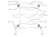
- FIG. 3 is a cross-sectional side view of a main part of the rotating electrical machine according to the second embodiment of the present invention.
- the stator 19, the stator core 20, the rotating shaft 21, the rotor 22, the frame 24, the insulator 26, and the coil 27 have the same structure and function as those described in the first embodiment.
- the end faces of the reinforcing ring 23 and the reinforcing ring 25 are different from those of the first embodiment in that they include protrusions 23a and 25a that protrude from the end face of the frame 24.
- the projecting parts 23a and 25a can be positioned with the bracket as a support member. That is, by assembling the reinforcing ring 23 and the reinforcing ring 25 having a length protruding in the axial direction from the end face of the frame 24 to the end face of the stator core 20, the fitting accuracy of the load side bracket 34 and the anti-load side bracket 43 is ensured. Is easily possible.
- the load side bracket 34 and the anti-load side bracket 43 are formed with positioning portions 34a and 43a corresponding to the protruding portions 23a and 25a (see FIG. 1).
- the rotating electrical machine 1 is not limited to an electric motor such as a motor, and includes a generator.
Landscapes
- Engineering & Computer Science (AREA)
- Power Engineering (AREA)
- Iron Core Of Rotating Electric Machines (AREA)
Abstract
Description
この結果、モータ軸方向中央部と比較し、負荷側及び反負荷側のステータコア内径寸法が小さくなるとともにステータコアを変形させていた。このようなステータコアの変形の結果、回転電機のコギングトルクが大きくなるという課題があった。
本発明はこのような課題に鑑みてなされたものであり、ステータコアの変形を改善することにより、コギングトルクを低減することができるステータおよび回転電機を提供することを目的とする。
本発明のステータは、電磁鋼板を積層して形成され筒状のフレームの内側に固定されたステータコアと、前記ステータコアに巻回されたコイルとからなるステータであって、前記フレームの軸方向寸法が、前記ステータコアの軸方向寸法より大きく形成されており、前記フレームの内側かつ前記ステータコアの両側に設けられ当該フレームをその内側から補強する補強部材を備えた。
また、本発明の回転電機は、電磁鋼板を積層して形成され筒状のフレームの内側に固定されたステータコアと、前記ステータコアに巻回されたコイルとからなるステータと、前記フレームの軸方向両端面に設けられたブラケットと、前記ブラケットに回転自在に支持された回転軸と、前記ステータの内側に設けられ前記回転軸とともに回転するロータとからなる回転電機であって、前記フレームの軸方向寸法が、前記ステータコアの軸方向寸法より大きく形成されており、前記フレームの内側かつ前記ステータコアの両側に設けられ当該フレームをその内側から補強する補強部材を備えた。
図1は本発明の第1実施形態における回転電機の側断面図である。以下、図1を用いて回転電機1の構造を説明する。ステータ10は、電磁鋼板を厚さ方向(図1では左右方向)に積層して形成されたステータコア11を備えている。回転軸12には、ロータ13が設けられている。ステータ10の内側に設けられたロータ13は回転軸12とともに回転する。
リング状部材である補強リング14は、筒状で内側に円柱状の空間を有するフレーム15の内側かつステータコア11の一方側(図1では右側)に設けられており、フレーム15をその内側から補強する補強部材として機能する。また、リング状部材である補強リング16は、筒状のフレーム15の内側かつステータコア11の他方側(図1では左側)に設けられており、フレーム15をその内側から補強する補強部材として機能する。したがって、補強部材としての補強リング14、16は、フレーム15の内側かつステータコア11の両側に設けられている。インシュレータ17は、ステータコア11に巻回されたコイル18を絶縁するものである。
なお、図1における補強リング14、16の形状は、便宜上、第2実施形態のものとなっている。
コイル18は、結線板45を介してリード線46に接続されている。リード線46は、台座28に固定されたレセプタクル29に接続されている。台座28は、回転電機1の外側に設けられている。
次に、本発明の第2実施形態を説明する。第2実施形態は、第1実施形態における補強リング14,16の形状に変更を加えたものである。その他の部分は、第1実施形態と同じである。
図3は本発明の第2実施形態における回転電機の要部側断面図である。図3において、ステータ19、ステータコア20、回転軸21、ロータ22、フレーム24、インシュレータ26、およびコイル27は、第1実施形態で説明したものと同等の構造および機能を有している。ただし、補強リング23および補強リング25の端面は、フレーム24の端面より突出した突出部23a、25aを備えた点が、第1実施形態のものと異なっている。
すなわち、フレーム24の端面より軸方向に突出した長さを有した補強リング23および補強リング25をステータコア20の端面に組み付けることにより、負荷側ブラケット34および反負荷側ブラケット43の嵌め込み精度を確保することが容易に可能となる。
なお、これらの負荷側ブラケット34および反負荷側ブラケット43には、突出部23a、25aに対応する位置決め部34a、43aが形成されている(図1参照)。
このようにして、補強リング23および補強リング25の端面が、フレーム24の端面より突出しており、補強リング23および補強リング25の端面の突出部23a、25aとこれらに対応する位置決め部34a、43aによって、フレーム24と負荷側ブラケット34および反負荷側ブラケット43が位置決めされている。
例えば、回転電機1はモータなどの電動機に限られるものではなく、発電機なども含むものである。
10 ステータ
11 ステータコア
12 回転軸
13 ロータ
14 補強リング
15 フレーム
16 補強リング
17 インシュレータ
18 コイル
19 ステータ
20 ステータコア
21 回転軸
22 ロータ
23 補強リング
23a 突出部
24 フレーム
25 補強リング
25a 突出部
26 インシュレータ
27 コイル
28 台座
29 リセプタクル
34 負荷側ブラケット
34a 位置決め部
35 封止樹脂
36 軸受
39 封止樹脂
43 反負荷側ブラケット
43a 位置決め部
44 軸受
45 結線板
46 リード線
Claims (12)
- 電磁鋼板を積層して形成され筒状のフレームの内側に固定されたステータコアと前記ステータコアに巻回されたコイルとからなるステータであって、
前記フレームの軸方向寸法が、前記ステータコアの軸方向寸法より大きく形成されており、
前記フレームの内側かつ前記ステータコアの両側に設けられ当該フレームをその内側から補強する補強部材を備えたことを特徴とするステータ。 - 前記補強部材の端面が、前記フレームの端面より突出したことを特徴とする請求項1記載のステータ。
- 前記補強部材が、前記フレームに内側から接触するリング状部材であることを特徴とする請求項1記載のステータ。
- 前記補強部材が、前記ステータコアの端面に接触するリング状部材であることを特徴とする請求項1記載のステータ。
- 前記補強部材の線膨張係数が、前記フレームの線膨張係数より小さいことを特徴とする請求項1記載のステータ。
- 前記フレームが、前記ステータコアに焼嵌めされたことを特徴とする請求項1記載のステータ。
- 電磁鋼板を積層して形成され筒状のフレームの内側に固定されたステータコアと前記ステータコアに巻回されたコイルとからなるステータと、前記フレームの軸方向両端面に設けられた支持部材と、前記支持部材に回転自在に支持された回転軸と、前記ステータの内側に設けられ前記回転軸とともに回転するロータとからなる回転電機であって、
前記フレームの軸方向寸法が、前記ステータコアの軸方向寸法より大きく形成されており、
前記フレームの内側かつ前記ステータコアの両側に設けられ当該フレームをその内側から補強する補強部材を備えたことを特徴とする回転電機。 - 前記補強部材の端面が、前記フレームの端面より突出しており、
前記補強部材の端面によって、前記フレームと前記支持部材が位置決めされたことを特徴とする請求項7記載の回転電機。 - 前記補強部材が、前記フレームに内側から接触するリング状部材であることを特徴とする請求項7記載の回転電機。
- 前記補強部材が、前記ステータコアの端面に接触するリング状部材であることを特徴とする請求項7記載の回転電機。
- 前記補強部材の線膨張係数が、前記フレームの線膨張係数より小さいことを特徴とする請求項7記載の回転電機。
- 前記フレームが、前記ステータコアに焼嵌めされたことを特徴とする請求項7記載の回転電機。
Priority Applications (2)
| Application Number | Priority Date | Filing Date | Title |
|---|---|---|---|
| CN2011800139678A CN102804551A (zh) | 2010-03-18 | 2011-01-07 | 定子和旋转电机 |
| JP2012505521A JPWO2011114758A1 (ja) | 2010-03-18 | 2011-01-07 | ステータおよび回転電機 |
Applications Claiming Priority (2)
| Application Number | Priority Date | Filing Date | Title |
|---|---|---|---|
| JP2010-062991 | 2010-03-18 | ||
| JP2010062991 | 2010-03-18 |
Publications (1)
| Publication Number | Publication Date |
|---|---|
| WO2011114758A1 true WO2011114758A1 (ja) | 2011-09-22 |
Family
ID=44648867
Family Applications (1)
| Application Number | Title | Priority Date | Filing Date |
|---|---|---|---|
| PCT/JP2011/050157 Ceased WO2011114758A1 (ja) | 2010-03-18 | 2011-01-07 | ステータおよび回転電機 |
Country Status (3)
| Country | Link |
|---|---|
| JP (1) | JPWO2011114758A1 (ja) |
| CN (1) | CN102804551A (ja) |
| WO (1) | WO2011114758A1 (ja) |
Cited By (3)
| Publication number | Priority date | Publication date | Assignee | Title |
|---|---|---|---|---|
| JP2015133807A (ja) * | 2014-01-10 | 2015-07-23 | 本田技研工業株式会社 | 電動機 |
| CN107404161A (zh) * | 2017-07-28 | 2017-11-28 | 安徽美芝精密制造有限公司 | 压缩机 |
| JP2024006181A (ja) * | 2022-07-01 | 2024-01-17 | 株式会社荏原製作所 | ポンプ装置 |
Citations (5)
| Publication number | Priority date | Publication date | Assignee | Title |
|---|---|---|---|---|
| JPH03284145A (ja) * | 1990-03-29 | 1991-12-13 | Toshiba Corp | 回転電機用積層鉄心 |
| JP2001025183A (ja) * | 1999-07-05 | 2001-01-26 | Nissan Motor Co Ltd | 電動機のステータ |
| JP2006087244A (ja) * | 2004-09-16 | 2006-03-30 | Asmo Co Ltd | 回転電機 |
| JP2007014175A (ja) * | 2005-07-04 | 2007-01-18 | Yaskawa Electric Corp | モータおよびその製造方法 |
| JP2009060760A (ja) * | 2007-09-03 | 2009-03-19 | Jtekt Corp | 電動モータ |
Family Cites Families (1)
| Publication number | Priority date | Publication date | Assignee | Title |
|---|---|---|---|---|
| JP2008178253A (ja) * | 2007-01-19 | 2008-07-31 | Fanuc Ltd | 電動機ロータの製造方法及び電動機 |
-
2011
- 2011-01-07 CN CN2011800139678A patent/CN102804551A/zh active Pending
- 2011-01-07 JP JP2012505521A patent/JPWO2011114758A1/ja active Pending
- 2011-01-07 WO PCT/JP2011/050157 patent/WO2011114758A1/ja not_active Ceased
Patent Citations (5)
| Publication number | Priority date | Publication date | Assignee | Title |
|---|---|---|---|---|
| JPH03284145A (ja) * | 1990-03-29 | 1991-12-13 | Toshiba Corp | 回転電機用積層鉄心 |
| JP2001025183A (ja) * | 1999-07-05 | 2001-01-26 | Nissan Motor Co Ltd | 電動機のステータ |
| JP2006087244A (ja) * | 2004-09-16 | 2006-03-30 | Asmo Co Ltd | 回転電機 |
| JP2007014175A (ja) * | 2005-07-04 | 2007-01-18 | Yaskawa Electric Corp | モータおよびその製造方法 |
| JP2009060760A (ja) * | 2007-09-03 | 2009-03-19 | Jtekt Corp | 電動モータ |
Cited By (3)
| Publication number | Priority date | Publication date | Assignee | Title |
|---|---|---|---|---|
| JP2015133807A (ja) * | 2014-01-10 | 2015-07-23 | 本田技研工業株式会社 | 電動機 |
| CN107404161A (zh) * | 2017-07-28 | 2017-11-28 | 安徽美芝精密制造有限公司 | 压缩机 |
| JP2024006181A (ja) * | 2022-07-01 | 2024-01-17 | 株式会社荏原製作所 | ポンプ装置 |
Also Published As
| Publication number | Publication date |
|---|---|
| CN102804551A (zh) | 2012-11-28 |
| JPWO2011114758A1 (ja) | 2013-06-27 |
Similar Documents
| Publication | Publication Date | Title |
|---|---|---|
| JP5879121B2 (ja) | アキシャルギャップ回転電機 | |
| US9219389B2 (en) | Permanent magnet rotating electrical machine | |
| US10050480B2 (en) | Axial flux machine having a lightweight design | |
| JP5920637B2 (ja) | 回転電機の回転子 | |
| JP6545393B2 (ja) | コンシクエントポール型の回転子、電動機および空気調和機 | |
| JPWO2017141412A1 (ja) | アキシャルギャップ回転電機 | |
| WO2018180720A1 (ja) | 電動モータおよびその製造方法 | |
| JP2013219904A (ja) | ステータの製造方法及びステータ | |
| US8823240B2 (en) | Stator and rotating electrical machine | |
| WO2021131575A1 (ja) | コイル及びそれを備えたステータ、モータ | |
| WO2011114758A1 (ja) | ステータおよび回転電機 | |
| JP2009177907A (ja) | 回転電動機のステータおよびそれを備えた回転電動機 | |
| JP2018074638A (ja) | ステータ、モータ、およびステータの製造方法 | |
| US11139714B2 (en) | Axial gap rotary electric machine | |
| JP2012044789A (ja) | 回転電機およびその製造方法 | |
| WO2017158700A1 (ja) | 回転電機、回転電機の製造方法 | |
| JP2015220950A (ja) | 回転電機 | |
| JP2011239626A (ja) | 回転電機 | |
| JP5564885B2 (ja) | 永久磁石形回転電機 | |
| WO2019064747A1 (ja) | ロータ及びそのロータを備えたモータ | |
| CN113472110B (zh) | 马达 | |
| CN113472168B (zh) | 马达 | |
| JP6230475B2 (ja) | 突極形回転子 | |
| CN113472169B (zh) | 马达 | |
| JP2012090486A (ja) | 回転電機の固定子 |
Legal Events
| Date | Code | Title | Description |
|---|---|---|---|
| WWE | Wipo information: entry into national phase |
Ref document number: 201180013967.8 Country of ref document: CN |
|
| 121 | Ep: the epo has been informed by wipo that ep was designated in this application |
Ref document number: 11755948 Country of ref document: EP Kind code of ref document: A1 |
|
| WWE | Wipo information: entry into national phase |
Ref document number: 2012505521 Country of ref document: JP |
|
| NENP | Non-entry into the national phase |
Ref country code: DE |
|
| 122 | Ep: pct application non-entry in european phase |
Ref document number: 11755948 Country of ref document: EP Kind code of ref document: A1 |