WO2011111368A1 - 白色照明装置 - Google Patents
白色照明装置 Download PDFInfo
- Publication number
- WO2011111368A1 WO2011111368A1 PCT/JP2011/001338 JP2011001338W WO2011111368A1 WO 2011111368 A1 WO2011111368 A1 WO 2011111368A1 JP 2011001338 W JP2011001338 W JP 2011001338W WO 2011111368 A1 WO2011111368 A1 WO 2011111368A1
- Authority
- WO
- WIPO (PCT)
- Prior art keywords
- phosphor
- blue
- white
- light emitting
- color rendering
- Prior art date
Links
Images

Classifications
-
- H—ELECTRICITY
- H05—ELECTRIC TECHNIQUES NOT OTHERWISE PROVIDED FOR
- H05B—ELECTRIC HEATING; ELECTRIC LIGHT SOURCES NOT OTHERWISE PROVIDED FOR; CIRCUIT ARRANGEMENTS FOR ELECTRIC LIGHT SOURCES, IN GENERAL
- H05B33/00—Electroluminescent light sources
- H05B33/12—Light sources with substantially two-dimensional radiating surfaces
- H05B33/14—Light sources with substantially two-dimensional radiating surfaces characterised by the chemical or physical composition or the arrangement of the electroluminescent material, or by the simultaneous addition of the electroluminescent material in or onto the light source
-
- C—CHEMISTRY; METALLURGY
- C09—DYES; PAINTS; POLISHES; NATURAL RESINS; ADHESIVES; COMPOSITIONS NOT OTHERWISE PROVIDED FOR; APPLICATIONS OF MATERIALS NOT OTHERWISE PROVIDED FOR
- C09K—MATERIALS FOR MISCELLANEOUS APPLICATIONS, NOT PROVIDED FOR ELSEWHERE
- C09K11/00—Luminescent, e.g. electroluminescent, chemiluminescent materials
- C09K11/08—Luminescent, e.g. electroluminescent, chemiluminescent materials containing inorganic luminescent materials
- C09K11/77—Luminescent, e.g. electroluminescent, chemiluminescent materials containing inorganic luminescent materials containing rare earth metals
- C09K11/7728—Luminescent, e.g. electroluminescent, chemiluminescent materials containing inorganic luminescent materials containing rare earth metals containing europium
- C09K11/7734—Aluminates
-
- C—CHEMISTRY; METALLURGY
- C09—DYES; PAINTS; POLISHES; NATURAL RESINS; ADHESIVES; COMPOSITIONS NOT OTHERWISE PROVIDED FOR; APPLICATIONS OF MATERIALS NOT OTHERWISE PROVIDED FOR
- C09K—MATERIALS FOR MISCELLANEOUS APPLICATIONS, NOT PROVIDED FOR ELSEWHERE
- C09K11/00—Luminescent, e.g. electroluminescent, chemiluminescent materials
- C09K11/08—Luminescent, e.g. electroluminescent, chemiluminescent materials containing inorganic luminescent materials
- C09K11/77—Luminescent, e.g. electroluminescent, chemiluminescent materials containing inorganic luminescent materials containing rare earth metals
- C09K11/7728—Luminescent, e.g. electroluminescent, chemiluminescent materials containing inorganic luminescent materials containing rare earth metals containing europium
- C09K11/77342—Silicates
-
- C—CHEMISTRY; METALLURGY
- C09—DYES; PAINTS; POLISHES; NATURAL RESINS; ADHESIVES; COMPOSITIONS NOT OTHERWISE PROVIDED FOR; APPLICATIONS OF MATERIALS NOT OTHERWISE PROVIDED FOR
- C09K—MATERIALS FOR MISCELLANEOUS APPLICATIONS, NOT PROVIDED FOR ELSEWHERE
- C09K11/00—Luminescent, e.g. electroluminescent, chemiluminescent materials
- C09K11/08—Luminescent, e.g. electroluminescent, chemiluminescent materials containing inorganic luminescent materials
- C09K11/77—Luminescent, e.g. electroluminescent, chemiluminescent materials containing inorganic luminescent materials containing rare earth metals
- C09K11/7728—Luminescent, e.g. electroluminescent, chemiluminescent materials containing inorganic luminescent materials containing rare earth metals containing europium
- C09K11/7737—Phosphates
- C09K11/7738—Phosphates with alkaline earth metals
- C09K11/7739—Phosphates with alkaline earth metals with halogens
-
- C—CHEMISTRY; METALLURGY
- C09—DYES; PAINTS; POLISHES; NATURAL RESINS; ADHESIVES; COMPOSITIONS NOT OTHERWISE PROVIDED FOR; APPLICATIONS OF MATERIALS NOT OTHERWISE PROVIDED FOR
- C09K—MATERIALS FOR MISCELLANEOUS APPLICATIONS, NOT PROVIDED FOR ELSEWHERE
- C09K11/00—Luminescent, e.g. electroluminescent, chemiluminescent materials
- C09K11/08—Luminescent, e.g. electroluminescent, chemiluminescent materials containing inorganic luminescent materials
- C09K11/77—Luminescent, e.g. electroluminescent, chemiluminescent materials containing inorganic luminescent materials containing rare earth metals
- C09K11/7783—Luminescent, e.g. electroluminescent, chemiluminescent materials containing inorganic luminescent materials containing rare earth metals containing two or more rare earth metals one of which being europium
- C09K11/7784—Chalcogenides
- C09K11/7787—Oxides
- C09K11/7789—Oxysulfides
-
- H—ELECTRICITY
- H01—ELECTRIC ELEMENTS
- H01L—SEMICONDUCTOR DEVICES NOT COVERED BY CLASS H10
- H01L33/00—Semiconductor devices with at least one potential-jump barrier or surface barrier specially adapted for light emission; Processes or apparatus specially adapted for the manufacture or treatment thereof or of parts thereof; Details thereof
- H01L33/48—Semiconductor devices with at least one potential-jump barrier or surface barrier specially adapted for light emission; Processes or apparatus specially adapted for the manufacture or treatment thereof or of parts thereof; Details thereof characterised by the semiconductor body packages
- H01L33/50—Wavelength conversion elements
- H01L33/507—Wavelength conversion elements the elements being in intimate contact with parts other than the semiconductor body or integrated with parts other than the semiconductor body
-
- H—ELECTRICITY
- H01—ELECTRIC ELEMENTS
- H01L—SEMICONDUCTOR DEVICES NOT COVERED BY CLASS H10
- H01L33/00—Semiconductor devices with at least one potential-jump barrier or surface barrier specially adapted for light emission; Processes or apparatus specially adapted for the manufacture or treatment thereof or of parts thereof; Details thereof
- H01L33/48—Semiconductor devices with at least one potential-jump barrier or surface barrier specially adapted for light emission; Processes or apparatus specially adapted for the manufacture or treatment thereof or of parts thereof; Details thereof characterised by the semiconductor body packages
- H01L33/50—Wavelength conversion elements
- H01L33/501—Wavelength conversion elements characterised by the materials, e.g. binder
- H01L33/502—Wavelength conversion materials
- H01L33/504—Elements with two or more wavelength conversion materials
-
- Y—GENERAL TAGGING OF NEW TECHNOLOGICAL DEVELOPMENTS; GENERAL TAGGING OF CROSS-SECTIONAL TECHNOLOGIES SPANNING OVER SEVERAL SECTIONS OF THE IPC; TECHNICAL SUBJECTS COVERED BY FORMER USPC CROSS-REFERENCE ART COLLECTIONS [XRACs] AND DIGESTS
- Y02—TECHNOLOGIES OR APPLICATIONS FOR MITIGATION OR ADAPTATION AGAINST CLIMATE CHANGE
- Y02B—CLIMATE CHANGE MITIGATION TECHNOLOGIES RELATED TO BUILDINGS, e.g. HOUSING, HOUSE APPLIANCES OR RELATED END-USER APPLICATIONS
- Y02B20/00—Energy efficient lighting technologies, e.g. halogen lamps or gas discharge lamps
Definitions
- Embodiments of the present invention relate to a white illumination device.
- a white illumination device using such a semiconductor light emitting element is highly efficient compared to conventional white illumination devices such as incandescent bulbs and fluorescent lamps, and thus greatly contributes to energy saving.
- a white illumination device using a semiconductor light emitting element does not necessarily have sufficient color rendering properties.
- the white lighting device using the semiconductor light emitting element can be used even in special lighting applications, which can greatly contribute to energy saving.
- Examples of a method for evaluating such color rendering properties include an average color rendering index Ra and special color rendering indices R9 to R15.
- the average color rendering index Ra and the special color rendering index R9 to R15 are all close to 100, they are suitable for special lighting applications.
- the special color rendering index R9 evaluates the appearance of red, and the closer the special color rendering index R9 is to 100, the higher the expression power of red.
- lamps called high color rendering are classified into three ranks of color rendering A, color rendering AA, and color rendering AAA.
- the average color rendering index Ra is required to be approximately 85 or higher, more preferably 90 or higher.
- the special color rendering index R9 is required to be about 85 or more, more preferably 90 or more.
- the above-described white light emitting devices using semiconductor light-emitting elements, particularly light-emitting diodes, are roughly classified into those using blue light-emitting diodes that emit blue light and those using near-ultraviolet light-emitting diodes that emit near-ultraviolet light.
- those using a blue light emitting diode include those combining a yellow phosphor and those combining a green phosphor and a red phosphor.
- average color rendering index Ra of 85 or more can be obtained, it is difficult to obtain special color rendering index R9 of 85 or more, and it uses for the use of special illumination. It ’s difficult.
- a problem to be solved by the present invention is a white illumination device that includes a semiconductor light emitting element that emits near-ultraviolet light and emits white light having a correlated color temperature of 5000 K or less, and has an average color rendering index Ra and a special color
- An object of the present invention is to provide a color rendering index R9 that is sufficiently high and that is suitably used for medical lighting, jewelry lighting, food lighting, photographing lighting, and the like.
- the white illumination device of the embodiment includes a semiconductor light emitting element that emits near-ultraviolet light, a blue-green phosphor having an emission peak in a wavelength region of 480 nm to 520 nm, and a red fluorescence having an emission peak in a wavelength region of 585 nm to 630 nm. And a phosphor layer containing two or more phosphors having an emission peak in a wavelength region other than these.
- the white illumination device of the embodiment emits white light having a correlated color temperature of 5000 K or less and a deviation duv from a black body locus of ⁇ 0.01 or more and 0.01 or less.
- the ratio of the content of the red phosphor to the content of the blue-green phosphor in the phosphor layer is 35 to 50.
- Sectional drawing which shows an example of the white illuminating device of embodiment.
- the figure which shows the emission spectrum of the white illuminating device of Example 1.
- FIG. 1 shows an example of the white illuminating device of embodiment.
- the figure which shows the emission spectrum of the white illuminating device of Example 1.
- the white illumination device of the embodiment includes a semiconductor light emitting device that emits near-ultraviolet light, a blue-green phosphor having an emission peak in a wavelength region of 480 nm to 520 nm, and a red fluorescence having an emission peak in a wavelength region of 585 nm to 630 nm.
- a phosphor layer containing two or more kinds of phosphors having emission peaks in other wavelength regions the correlated color temperature is 5000 K or less, and the deviation duv from the black body locus is ⁇ 0.01 or more It emits white light of 0.01 or less, and the ratio of the content of the red phosphor to the content of the blue-green phosphor in the phosphor layer is 35 to 50.
- FIG. 1 is a cross-sectional view illustrating an example of the white illumination device of the embodiment.
- the white illumination device 1 includes a semiconductor light emitting element (chip) 2 as an excitation source (light source).
- the semiconductor light emitting element 2 emits near-ultraviolet light, and specifically emits light having an emission peak in a wavelength region of 360 nm to 440 nm, preferably 380 nm to 410 nm.
- the semiconductor light emitting element 2 for example, an ultraviolet light emitting diode, a violet light emitting diode, an ultraviolet light emitting laser (laser diode), a violet light emitting laser (laser diode), or the like is used.
- the light emitting diode for example, a light emitting diode of InGaN, GaN, AlGaN, or the like is used.
- the correlated color temperature is 5000 K or less
- the average color rendering index Ra and the special color rendering index R9 are sufficiently high
- medical lighting and jewelry It can be set as the white illuminating device 1 used suitably for the illumination for food, the illumination for food, the illumination for imaging
- the semiconductor light emitting element 2 is mounted on the substrate 3.
- a wiring substrate having a wiring network on the surface or inside is used as the substrate 3.
- the electrodes of the semiconductor light emitting element 2 are electrically connected to the wiring network of the wiring substrate 3, and thereby a DC voltage is applied to the semiconductor light emitting element 2.
- the semiconductor light emitting device 2 is covered with a transparent resin layer 4 in order to improve the light utilization efficiency.
- the transparent resin layer 4 is formed in, for example, a hemispherical shape that covers the entire semiconductor light emitting element 2 as shown in the figure, but it is sufficient that it is formed so as to cover at least the light emitting surface of the semiconductor light emitting element 2.
- the white illuminating device 1 of embodiment it is not necessary to necessarily provide the transparent resin layer 4, and you may make it form the fluorescent substance layer 5 mentioned later directly on the semiconductor light-emitting device 2.
- a phosphor layer 5 is formed on the transparent resin layer 4 covering the semiconductor light emitting element 2.
- the phosphor layer 5 is obtained by dispersing a phosphor 7 for obtaining white light in a resin 6 having transparency.
- the phosphor 7 is excited by light emitted from the semiconductor light emitting element 2 and emits white light as a total.
- the resin having transparency that constitutes the transparent resin layer 4 and the phosphor layer 5 is made of a resin having transparency such as a silicone resin or an epoxy resin.
- the phosphor 7 for obtaining white light is a blue-green phosphor that absorbs light (for example, ultraviolet light or violet light) emitted from the semiconductor light emitting element 2 and emits blue-green light, and is emitted from the semiconductor light emitting element 2. It contains at least a red phosphor that absorbs light and emits red light. That is, the phosphor 7 is a mixed phosphor containing at least a blue-green phosphor and a red phosphor. In general, the phosphor 7 absorbs light emitted from the semiconductor light emitting element 2 and emits blue light in addition to the blue-green phosphor and red phosphor described above, and emits from the semiconductor light emitting element 2. It is composed of a yellow phosphor that absorbs the emitted light and emits yellow light.
- the blue-green phosphor specifically emits light having an emission peak in a wavelength region of 480 nm or more and 520 nm or less when excited by light emitted from the semiconductor light emitting element 2.
- the red phosphor emits light having a light emission peak in a wavelength region of 585 nm to 630 nm
- the blue phosphor has a light emission peak in a wavelength region of 440 nm to 460 nm
- the phosphor has an emission peak in a wavelength region of 525 nm or more and 575 nm or less.
- the phosphors of the respective colors constituting the phosphor 7, that is, the blue-green phosphor, the red phosphor, the blue phosphor, and the yellow phosphor may each consist of only one kind of phosphor, or two kinds You may consist of the above fluorescent substance.
- the phosphor 7 may supplementarily include phosphors having other emission colors, such as orange phosphors, deep red phosphors, and the like. These blue-green phosphors, red phosphors, blue phosphors, and yellow phosphors may be dispersed in the phosphor layer 5 in a state of being bound in advance by a binder.
- Electrical energy applied to the white illumination device 1 is converted into ultraviolet light or violet light by the semiconductor light emitting element 2.
- Light emitted from the semiconductor light emitting element 2 is converted into light having a long wavelength by the phosphor 7 dispersed in the phosphor layer 5.
- the light emitted from the blue-green phosphor, red phosphor, blue phosphor, and yellow phosphor constituting the phosphor 7 is mixed and emitted, so that white light is emitted as a total.
- a phosphor containing at least a blue-green phosphor and a red phosphor is used as the phosphor 7, and red with respect to the content of the blue-green phosphor in the phosphor layer 5 (phosphor 7).
- the ratio of the phosphor content in mass is from 35 to 50.
- the special color rendering index R9 is a red color rendering index, and can be improved by increasing the content of the red phosphor. However, if the content of the red phosphor is simply increased, the target correlated color temperature is exceeded. Also tends to be reddish.
- a blue-green phosphor that emits blue-green light which is a complementary color of red light, is used in combination, thereby suppressing a change from the target correlated color temperature and red compared to the conventional one.
- the phosphor content can be increased.
- an average color rendering index Ra and a special color rendering index R9 of 85 or more are more preferable.
- the correlated color temperature is not necessarily limited as long as it is 5000K or lower, but is usually 2600K or higher.
- the correlated color temperature and the deviation duv from the black body locus are evaluated according to the evaluation method disclosed in JIS Z8725.
- the average color rendering index Ra and the special color rendering index R9 are evaluated according to the color rendering evaluation method disclosed in JIS Z8726.
- a sufficiently high special color rendering index R9 such as 85 or more may not be obtained.
- the ratio of the content of the red phosphor to the content of the blue-green phosphor exceeds 50, a sufficiently high special color rendering index R9 can be obtained, but the correlated color temperature tends to be reddish.
- the ratio of the content of the red phosphor to the total amount of the phosphor 7, that is, the total amount of the blue-green phosphor, the red phosphor, the blue phosphor, and the yellow phosphor is the target correlated color temperature and the average color rendering index. Although it varies depending on the Ra, the special color rendering index R9, and the content ratio of the red phosphor relative to the blue-green phosphor, it is preferably 45% by mass to 85% by mass, more preferably 50% by mass to 80% by mass. It is.
- a sufficiently high special color rendering index R9 may not be obtained.
- the ratio of the content of the red phosphor with respect to the total amount of the phosphor 7 exceeds 85% by mass, a sufficiently high special color rendering index R9 can be obtained, but the correlated color temperature tends to be reddish.
- the ratio of the content of the blue phosphor and the yellow phosphor with respect to the total amount of the phosphor 7 also varies depending on the target correlated color temperature and the like.
- the ratio of the content of the blue phosphor is 10% by mass or more and 50% by mass or less.
- 15 mass% or more and 45 mass% or less are more preferable.
- the content ratio of the yellow phosphor is, for example, preferably 1% by mass to 10% by mass, and more preferably 1% by mass to 7% by mass.
- the blue-green phosphor, the red phosphor, the blue phosphor, and the yellow phosphor each efficiently absorbs ultraviolet light and violet light emitted from the semiconductor light-emitting element 2 and has a light emission peak in the wavelength region described above. It is not necessarily limited as long as it emits light. However, if the luminance difference between the colors is large, a high-luminance color is likely to become white light, and in order to improve the color rendering of white light, It is necessary to improve the balance. For this reason, as the blue-green phosphor, red phosphor, blue phosphor and yellow phosphor constituting the phosphor 7, it is preferable to use the following combinations.
- Europium-activated barium strontium orthosilicate phosphor as a blue-green phosphor represented by the general formula (1) is excellent in absorption efficiency of ultraviolet light and violet light having an emission peak in a wavelength region of 360 nm to 440 nm, and red Can be efficiently emitted.
- the special color rendering index R9 can be effectively improved by increasing the content of the red phosphor while suppressing the correlated color temperature from becoming reddish.
- a europium-activated lanthanum oxysulfide phosphor having a composition represented by the formula:
- the europium-activated lanthanum oxysulfide phosphor as a red phosphor represented by the general formula (2) is excellent in absorption efficiency of ultraviolet light and violet light having a peak wavelength in a wavelength region of 360 nm or more and 440 nm or less, and the general formula ( The combination with the europium-activated barium strontium orthosilicate phosphor as the blue-green phosphor shown in 1) is also excellent.
- the europium activated alkaline earth chlorophosphate phosphor as the blue phosphor represented by the general formula (3) is also excellent in absorption efficiency of ultraviolet light and violet light having a peak wavelength in a wavelength region of 360 nm to 440 nm,
- the combination with the europium-activated barium strontium orthosilicate phosphor as the blue-green phosphor represented by the general formula (1) is also excellent.
- Europium and manganese-activated alkaline earth magnesium silicate phosphors represented by the general formula (4) are, for example, a wavelength region of 360 nm or more and 440 nm or less as shown in International Publication No. 2008/096545 pamphlet. It has excellent absorption efficiency of ultraviolet light and violet light having a light emission peak, and has a higher light emission intensity in the range of 600 nm to 700 nm than conventional yellow phosphors, and can effectively reinforce red light emission. Moreover, since it has a sub-peak in the vicinity of 450 nm, blue light emission can be reinforced. Thereby, it can be set as the white light which is excellent in a brightness
- the above-described phosphors of the respective colors each preferably have an average particle diameter of 5 ⁇ m or more and 80 ⁇ m or less.
- an average particle diameter shall show the median value (50% value) of a particle size distribution.
- the transparent resin layer 4 preferably has a thickness on the light emitting surface of the semiconductor light emitting element 2 of 0.4 mm or more and 10 mm or less, for example.
- a thickness on the light emitting surface of the semiconductor light emitting element 2 of 0.4 mm or more and 10 mm or less, for example.
- the thickness of the transparent resin layer 4 is preferably 10 mm or less.
- the thickness of the transparent resin layer 4 is preferably 0.8 mm or more, and more preferably 1 mm or more. Moreover, when making it hemispherical as shown in FIG. 1, it is preferable that the radius of a hemispherical part shall be 0.4 mm or more and 10 mm or less. Moreover, it is preferable that the thickness of the fluorescent substance layer formed on such a transparent resin layer 4 is 0.1 mm or more and 2.0 mm or less.
- the white illumination device 1 of the embodiment can be manufactured as follows, for example. First, a phosphor slurry containing phosphor powders of each color is prepared.
- the phosphor slurry can be prepared, for example, by mixing each color phosphor powder with a resin and then mixing them.
- the phosphor slurry can be prepared by previously mixing phosphor powders of respective colors and then mixing the mixed phosphor powder with a resin.
- the mixing ratio of the phosphor powder and the resin can be appropriately selected according to the type and particle size of the phosphor powder. For example, 5 parts by mass or more and 100 parts by mass of the resin with respect to 100 parts by mass of the phosphor powder. The following is preferable. In addition, it is preferable to adjust the mixing ratio of the phosphor powders of the respective colors so as to have the content ratio as described above. Mixing of the phosphor powder and the resin can be performed using, for example, a known stirrer.
- a liquid transparent resin is applied on the semiconductor light emitting element 2 and solidified to form a transparent resin layer 4.
- a phosphor slurry is applied from above, and the resin in the phosphor slurry is solidified to form the phosphor layer 5. In this way, the white lighting device 1 can be manufactured.
- the application of the transparent resin or the phosphor slurry can be performed, for example, by placing the wiring substrate 3 on which the semiconductor light emitting element 2 is mounted in a mold and supplying the transparent resin or the phosphor slurry with a dispenser.
- coating of transparent resin and fluorescent substance slurry can also be performed by the printing method, the injection molding method, etc., for example.
- a thermosetting resin is used as the resin in the transparent resin or phosphor slurry
- the resin is placed in an oven or the like and heated to a temperature of 100 to 200 ° C. to be cured.
- the layer 4 and the phosphor layer 5 can be formed.
- the white illumination device 1 emits white light having a correlated color temperature of 5000 K or less and a deviation duv from a black body locus of ⁇ 0.01 or more and 0.01 or less.
- the average color rendering index Ra and special color rendering index R9 are as high as 85 or more, respectively. Since such a white lighting device 1 has a sufficiently high average color rendering index Ra and special color rendering index R9, it is preferably used for medical lighting, jewelry lighting, food lighting, photographing lighting, and the like. Can greatly contribute to energy saving.
- Example 1 A white illumination device as shown in FIG. 1 was manufactured as the white illumination device. First, as a blue-green phosphor powder, a red phosphor powder, a blue phosphor powder, and a yellow phosphor powder, those having a composition and an average particle diameter as shown in Table 1 are used, and these are shown in Table 1. Were mixed and mixed to obtain a mixed phosphor powder. A phosphor slurry to be a phosphor layer 5 was prepared by mixing 60 parts by mass of a silicone resin with 40 parts by mass of the mixed phosphor powder.
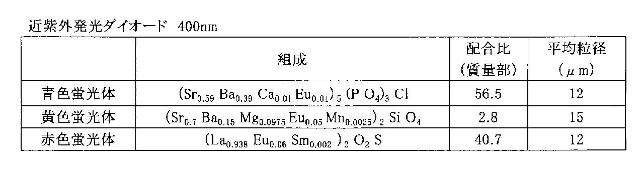
- Example 2 As shown in Table 2, the correlated color temperature is within the range of 4000 to 5000 K in the same manner as in Example 1 except that a near ultraviolet light emitting diode having an emission peak wavelength of 400 nm is used and a red phosphor powder having a different composition is used. A white lighting device was manufactured.
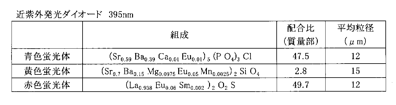
- Example 3 As shown in Table 3, the correlated color temperature is within the range of 4000 to 5000 K in the same manner as in Example 1 except that a near ultraviolet light emitting diode having an emission peak wavelength of 395 nm is used and a red phosphor powder having a different composition is used. A white lighting device was manufactured.
- Example 4 As shown in Table 4, a white lighting device was manufactured in the same manner as in Example 1 except that the blending ratio of the phosphor powders of the respective colors was changed so that the correlated color temperature was in the range of 2500 to 4000K.
- Example 5 As shown in Table 5, the correlated color temperature is in the range of 2500 to 4000 K in the same manner as in Example 4 except that a near-ultraviolet light emitting diode having an emission peak wavelength of 400 nm is used and a red phosphor powder having a different composition is used. A white lighting device was manufactured.
- Example 6 As shown in Table 6, the correlated color temperature is the same as in Example 1 except that the blending ratio of the phosphors of each color is changed so that the blending ratio of the red phosphor powder to the blue-green phosphor powder is about 35. A white lighting device having a range of 4000 to 5000K was manufactured.
- Example 7 As shown in Table 7, the mixing ratio of the phosphors of the respective colors so that the correlated color temperature is in the range of 2500 to 4000 K and the mixing ratio of the red phosphor powder to the blue-green phosphor powder is about 50.
- a white lighting device was manufactured in the same manner as in Example 1 except that the above was changed.
- Example 1 As shown in Table 8, a near ultraviolet light emitting diode having an emission peak wavelength of 395 nm was used, and only a red phosphor powder, a blue phosphor powder, and a yellow phosphor powder were blended so that the correlated color temperature was 4000 to 5000K.
- a white lighting device was manufactured in the same manner as Example 1 except for the above.
- Comparative Example 4 As shown in Table 11, except that a near-ultraviolet light emitting diode having an emission peak wavelength of 405 nm was used and a red phosphor powder, a blue phosphor powder, and a yellow phosphor powder were blended so that the correlated color temperature was less than 3000K. A white lighting device was manufactured in the same manner as in Comparative Example 1.
- Table 12 shows the evaluation results such as the luminous flux and chromaticity coordinate values of the white illumination device of Example 1. Moreover, the emission spectrum of the white illuminating device of Example 1 is shown in FIG. Further, Table 13 shows the color temperature (correlated color temperature), deviation duv (deviation duv from the black body locus), luminous efficiency, average color rendering index Ra, and special color rendering evaluation of the white lighting devices of the examples and comparative examples. The evaluation result of number R9 is shown collectively. The evaluation was performed using CAS 140 COMPACT ARRAY SPECTROMETER manufactured by Instrument System, and MCPD device manufactured by Otsuka Electronics Co., Ltd.
- the correlated color temperature is It can be seen that an average color rendering index Ra and a special color rendering index R9 of 90 or more can be obtained for those of 5000K or less.
- SYMBOLS 1 White illumination device, 2 ... Semiconductor light emitting element, 3 ... Wiring board, 4 ... Transparent resin layer, 5 ... Phosphor layer, 6 ... Resin, 7 ... Phosphor
Abstract
実施形態によれば、近紫外光を発光する半導体発光素子2と、青緑色光を発光する青緑色蛍光体および赤色光を発光する赤色蛍光体を少なくとも含有する蛍光体層5とを具備し、相関色温度が5000K以下かつ黒体軌跡からの偏差duvが-0.01以上0.01以下である白色光を発光し、蛍光体層5における青緑色蛍光体の含有量に対する赤色蛍光体の含有量の質量での割合が35以上50以下であるものが提供される。
Description
本発明の実施形態は白色照明装置に関する。
近年、発光ダイオード(Light Emitting Diode:LED)等の半導体発光素子と、この半導体発光素子からの発光により励起して発光する蛍光体とを組み合わせた高効率な白色照明装置が製品化されつつある。このような半導体発光素子を用いた白色照明装置は、白熱電球や蛍光灯等の従来の白色照明装置と比較して高効率であることから、省エネルギー化に大きく貢献する。
ところで、医療用照明、宝飾品用照明、食品用照明、撮影用照明等、自然光での色の見え方に近いことが必要とされる特殊照明の用途では高い演色性を有することが求められるが、半導体発光素子を用いた白色照明装置については必ずしも十分な演色性を有していない。半導体発光素子を用いた白色照明装置の演色性を向上させることで、特殊照明の用途においても半導体発光素子を用いた白色照明装置の使用が可能となり、省エネルギー化に大きく貢献することができる。
このような演色性を評価する方法として、平均演色評価数Raおよび特殊演色評価数R9~R15が挙げられる。平均演色評価数Raおよび特殊演色評価数R9~R15は、いずれも100に近いときに特殊照明の用途において好適となる。特に、特殊演色評価数R9は赤色の見え方を評価するものであり、特殊演色評価数R9が100に近いほど赤色の表現力が高いといえる。
JIS演色評価方法において、高演色形と呼ばれるランプは、演色A、演色AA、演色AAAの3ランクに分類されている。このうち演色AA以上のランプと代替するには、平均演色評価数Raが約85以上、より好ましくは90以上が求められる。また、赤色を再現性よく表現するには、特殊演色評価数R9が約85以上、より好ましくは90以上が求められる。
上記した半導体発光素子、特に発光ダイオードを用いる白色照明装置には、大別して、青色光を発光する青色発光ダイオードを用いるものと、近紫外光を発光する近紫外発光ダイオードを用いるものとがある。
このうち青色発光ダイオードを用いるものとしては、黄色蛍光体を組み合わせるものや、緑色蛍光体および赤色蛍光体を組み合わせるものが挙げられる。しかしながら、黄色蛍光体を組み合わせるものについては、85以上の平均演色評価数Raを得ることが難しく、特殊照明の用途に用いることは難しい。また、緑色蛍光体および赤色蛍光体を組み合わせるものについては、85以上の平均演色評価数Raを得ることができるが、85以上の特殊演色評価数R9を得ることが難しく、特殊照明の用途に用いることは難しい。
一方、近紫外発光ダイオードを用いるものとしては、青色蛍光体、緑色蛍光体、および赤色蛍光体を組み合わせるもの、また緑色蛍光体の代わりに黄色蛍光体を組み合わせるものが知られている(例えば、特許文献1参照)。このようなものによれば、相関色温度が5000Kを超えるものについて、85以上の平均演色評価数Raおよび特殊演色評価数R9を得ることができ、特殊照明の用途に用いることができる。しかしながら、相関色温度が5000K以下のものについては、85以上の平均演色評価数Raおよび特殊演色評価数R9を得ることが難しく、特に85以上の特殊演色評価数R9を得ることが難しく、特殊照明の用途に用いることは難しい。
本発明が解決しようとする課題は、近紫外光を発光する半導体発光素子を具備し、相関色温度が5000K以下である白色光を発光する白色照明装置であって、平均演色評価数Raおよび特殊演色評価数R9が十分に高く、医療用照明、宝飾品用照明、食品用照明、撮影用照明等に好適に用いられるものを提供することにある。
実施形態の白色照明装置は、近紫外光を発光する半導体発光素子と、480nm以上520nm以下の波長領域に発光ピークを有する青緑色蛍光体、585nm以上630nm以下の波長領域に発光ピークを有する赤色蛍光体、およびこれら以外の波長領域に発光ピークを有する2種以上の蛍光体を含有する蛍光体層とを具備する。実施形態の白色照明装置は、相関色温度が5000K以下かつ黒体軌跡からの偏差duvが-0.01以上0.01以下である白色光を発光する。実施形態の白色照明装置は、蛍光体層における青緑色蛍光体の含有量に対する赤色蛍光体の含有量の質量での割合が35以上50以下である。
以下、実施形態の白色照明装置について具体的に説明する。
実施形態の白色照明装置は、近紫外光を発光する半導体発光素子と、480nm以上520nm以下の波長領域に発光ピークを有する青緑色蛍光体、585nm以上630nm以下の波長領域に発光ピークを有する赤色蛍光体、およびこれら以外の波長領域に発光ピークを有する2種以上の蛍光体を含有する蛍光体層とを具備し、相関色温度が5000K以下かつ黒体軌跡からの偏差duvが-0.01以上0.01以下である白色光を発光するものであって、上記蛍光体層における青緑色蛍光体の含有量に対する赤色蛍光体の含有量の質量での割合が35以上50以下である。
実施形態の白色照明装置は、近紫外光を発光する半導体発光素子と、480nm以上520nm以下の波長領域に発光ピークを有する青緑色蛍光体、585nm以上630nm以下の波長領域に発光ピークを有する赤色蛍光体、およびこれら以外の波長領域に発光ピークを有する2種以上の蛍光体を含有する蛍光体層とを具備し、相関色温度が5000K以下かつ黒体軌跡からの偏差duvが-0.01以上0.01以下である白色光を発光するものであって、上記蛍光体層における青緑色蛍光体の含有量に対する赤色蛍光体の含有量の質量での割合が35以上50以下である。
図1は、実施形態の白色照明装置の一例を示す断面図である。
白色照明装置1は、励起源(光源)としての半導体発光素子(チップ)2を有している。半導体発光素子2は、近紫外光を発光するものであり、具体的には360nm以上440nm以下、好ましくは380nm以上410nm以下の波長領域に発光ピークを有する光を出射するものである。半導体発光素子2としては、例えば紫外発光ダイオード、紫色発光ダイオード、紫外発光レーザ(レーザダイオード)、紫色発光レーザ(レーザダイオード)等が用いられる。このうち発光ダイオードとしては、例えばInGaN系、GaN系、AlGaN系等の発光ダイオードが用いられる。
白色照明装置1は、励起源(光源)としての半導体発光素子(チップ)2を有している。半導体発光素子2は、近紫外光を発光するものであり、具体的には360nm以上440nm以下、好ましくは380nm以上410nm以下の波長領域に発光ピークを有する光を出射するものである。半導体発光素子2としては、例えば紫外発光ダイオード、紫色発光ダイオード、紫外発光レーザ(レーザダイオード)、紫色発光レーザ(レーザダイオード)等が用いられる。このうち発光ダイオードとしては、例えばInGaN系、GaN系、AlGaN系等の発光ダイオードが用いられる。
このような半導体発光素子2と後述する蛍光体とを組み合わせることによって、相関色温度が5000K以下であって、平均演色評価数Raおよび特殊演色評価数R9が十分に高く、医療用照明、宝飾品用照明、食品用照明、撮影用照明等に好適に用いられる白色照明装置1とすることができる。
半導体発光素子2は基板3上に実装されている。基板3としては表面や内部に配線網を有する配線基板が用いられる。図示を省略したが、半導体発光素子2の電極は配線基板3の配線網と電気的に接続されており、これによって半導体発光素子2に直流電圧が印加される。
半導体発光素子2は、光の利用効率を向上させるために透明樹脂層4で覆われている。透明樹脂層4は、例えば図示するような半導体発光素子2の全体を覆う半球状に形成されるが、少なくとも半導体発光素子2の発光面を覆うように形成されていればよい。なお、実施形態の白色照明装置1については、必ずしも透明樹脂層4を設ける必要はなく、後述する蛍光体層5を半導体発光素子2上に直接形成するようにしてもよい。
半導体発光素子2を覆う透明樹脂層4上には蛍光体層5が形成されている。蛍光体層5は、透明性を有する樹脂6に白色光を得るための蛍光体7が分散されたものである。蛍光体7は、半導体発光素子2から出射される光により励起されて総計として白色光を発光するものである。透明樹脂層4や蛍光体層5を構成する透明性を有する樹脂は、例えばシリコーン樹脂やエポキシ樹脂等の透明性を有する樹脂からなるものである。
白色光を得るための蛍光体7は、半導体発光素子2から出射される光(例えば紫外光や紫色光)を吸収して青緑光を発光する青緑色蛍光体、および半導体発光素子2から出射される光を吸収して赤色光を発光する赤色蛍光体を少なくとも含有することにより構成されている。すなわち、蛍光体7は、少なくとも青緑色蛍光体および赤色蛍光体を含有する混合蛍光体である。通常、蛍光体7は、上記した青緑色蛍光体および赤色蛍光体に加えて、半導体発光素子2から出射された光を吸収して青色光を発光する青色蛍光体、および半導体発光素子2から出射された光を吸収して黄色光を発光する黄色蛍光体から構成される。
ここで、青緑色蛍光体とは、具体的には半導体発光素子2からの発光により励起して480nm以上520nm以下の波長領域に発光ピークを有する発光を行うものである。同様に、赤色蛍光体とは、585nm以上630nm以下の波長領域に発光ピークを有する発光を行うものであり、青色蛍光体は、440nm以上460nm以下の波長領域に発光ピークを有するものであり、黄色蛍光体は、525nm以上575nm以下の波長領域に発光ピークを有するものである。
蛍光体7を構成する各色の蛍光体、すなわち青緑色蛍光体、赤色蛍光体、青色蛍光体、および黄色蛍光体は、それぞれ1種の蛍光体のみからなるものであってもよいし、2種以上の蛍光体からなるものであってもよい。また、蛍光体7は、これ以外の発光色を有する蛍光体、例えば橙色蛍光体、深赤色蛍光体等を補助的に含んでいてもよい。これら青緑色蛍光体、赤色蛍光体、青色蛍光体、および黄色蛍光体は、予め結合剤により結合された状態で蛍光体層5に分散されていてもよい。
白色照明装置1に印加された電気エネルギーは、半導体発光素子2で紫外光や紫色光に変換される。半導体発光素子2から出射された光は、蛍光体層5に分散された蛍光体7により長波長の光に変換される。そして、蛍光体7を構成する青緑色蛍光体、赤色蛍光体、青色蛍光体、および黄色蛍光体からの発光が混色されて放出されることによって、総計として白色光が発光される。
実施形態の白色照明装置1では、蛍光体7として少なくとも青緑色蛍光体および赤色蛍光体を含有するものを用い、かつ蛍光体層5(蛍光体7)中における青緑色蛍光体の含有量に対する赤色蛍光体の含有量の質量での割合(赤色蛍光体の含有量/青緑色蛍光体の含有量)を35以上50以下とすることを特徴としている。このようなものとすることで、相関色温度が5000K以下かつ黒体軌跡からの偏差duvが-0.01以上0.01以下である白色光を発光するものであって、平均演色評価数Raおよび特殊演色評価数R9が十分に高いものとすることができる。
従来の蛍光体の組み合わせ、すなわち赤色蛍光体、青色蛍光体、および緑色蛍光体の組み合わせ、または赤色蛍光体、青色蛍光体、および黄色蛍光体の組み合わせについては、相関色温度が5000Kを超えるものについては、十分な平均演色評価数Raおよび特殊演色評価数R9を得ることができるが、相関色温度が5000K以下のものについては、必ずしも十分な特殊演色評価数R9を得ることができない。特殊演色評価数R9は赤色の演色評価数であり、赤色蛍光体の含有量を多くすることで向上させることができるが、単に赤色蛍光体の含有量を多くすると、目的とする相関色温度よりも赤みを帯びたものとなりやすい。
実施形態の白色照明装置1では、赤色光の補色である青緑色光を発光する青緑色蛍光体を併用することで、目的とする相関色温度からの変化を抑制しつつ、従来に比べて赤色蛍光体の含有量を多くすることができる。これにより、相関色温度が5000K以下かつ黒体軌跡からの偏差duvが-0.01以上0.01以下であるものについて、例えば85以上の平均演色評価数Raおよび特殊演色評価数R9、より好ましくは90以上の平均演色評価数Raおよび特殊演色評価数R9を有するものとすることができる。
相関色温度は5000K以下であれば必ずしも限定されるものではないが、通常は2600K以上である。なお、相関色温度および黒体軌跡からの偏差duvは、JIS Z8725に開示される評価手法に準じて評価されるものである。さらに、平均演色評価数Ra、特殊演色評価数R9は、JIS Z8726に開示される演色評価手法に準じて評価されるものである。
青緑色蛍光体の含有量に対する赤色蛍光体の含有量の割合が35未満であると、例えば85以上といった十分に高い特殊演色評価数R9を得られないおそれがある。一方、青緑色蛍光体の含有量に対する赤色蛍光体の含有量の割合が50を超えると、十分に高い特殊演色評価数R9を得られるが、相関色温度が赤みを帯びたものとなりやすい。
蛍光体7の合計量、すなわち青緑色蛍光体、赤色蛍光体、青色蛍光体、および黄色蛍光体の合計量に対する赤色蛍光体の含有量の割合は、目的とする相関色温度、平均演色評価数Ra、および特殊演色評価数R9、また青緑色蛍光体に対する赤色蛍光体の含有割合によっても異なるが、好ましくは45質量%以上85質量%以下であり、より好ましくは50質量%以上80質量%以下である。
蛍光体7の合計量に対する赤色蛍光体の含有量の割合が45質量%未満であると、十分に高い特殊演色評価数R9を得られないおそれがある。一方、蛍光体7の合計量に対する赤色蛍光体の含有量の割合が85質量%を超えると、十分に高い特殊演色評価数R9を得られるが、相関色温度が赤みを帯びたものとなりやすい。
蛍光体7の合計量に対する青色蛍光体および黄色蛍光体の含有量の割合も目的とする相関色温度等によって異なるが、例えば青色蛍光体の含有量の割合は10質量%以上50質量%以下が好ましく、15質量%以上45質量%以下がより好ましい。また、黄色蛍光体の含有量の割合は、例えば1質量%以上10質量%以下が好ましく、1質量%以上7質量%以下が好ましい。
青緑色蛍光体、赤色蛍光体、青色蛍光体、および黄色蛍光体としては、それぞれ半導体発光素子2から出射される紫外光や紫色光を効率よく吸収して、上記した波長領域に発光ピークを有する発光を行うものであれば必ずしも限定されるものではないが、各色の輝度差が大きいと輝度の高い色が勝った白色光となりやすく、また白色光の演色性を向上させるためには、各色のバランスを高める必要がある。このため、蛍光体7を構成する青緑色蛍光体、赤色蛍光体、青色蛍光体、および黄色蛍光体としては、以下に示すものを組み合わせて用いることが好ましい。
青緑色蛍光体としては、
一般式:(Ba1-x-ySrxEuy)2SiO4 …(1)
(式中、xは0≦x<0.5、yは0.005≦y<0.25を満足する数である)
で表わされる組成を有するユーロピウム付活バリウムストロンチウムオルソ珪酸塩蛍光体が好適に用いられる。
一般式:(Ba1-x-ySrxEuy)2SiO4 …(1)
(式中、xは0≦x<0.5、yは0.005≦y<0.25を満足する数である)
で表わされる組成を有するユーロピウム付活バリウムストロンチウムオルソ珪酸塩蛍光体が好適に用いられる。
一般式(1)で示される青緑色蛍光体としてのユーロピウム付活バリウムストロンチウムオルソ珪酸塩蛍光体は、360nm以上440nm以下の波長領域に発光ピークを有する紫外光や紫色光の吸収効率に優れ、赤色の補色である青緑色を効率的に発光することができる。これにより相関色温度が赤みを帯びたものとなることを抑制しつつ、赤色蛍光体の含有量を増加させて特殊演色評価数R9を効果的に向上させることができる。
赤色蛍光体としては、
一般式:(La1-x-yEuxMy)2O2S …(2)
(式中、MはSm、Ga、SbおよびSnから選ばれる少なくとも1種を示し、xおよびyは0.008≦x<0.16、0.000001≦y<0.003を満足する数である)
で表される組成を有するユーロピウム付活酸硫化ランタン蛍光体が好適に用いられる。
一般式:(La1-x-yEuxMy)2O2S …(2)
(式中、MはSm、Ga、SbおよびSnから選ばれる少なくとも1種を示し、xおよびyは0.008≦x<0.16、0.000001≦y<0.003を満足する数である)
で表される組成を有するユーロピウム付活酸硫化ランタン蛍光体が好適に用いられる。
一般式(2)で示される赤色蛍光体としてのユーロピウム付活酸硫化ランタン蛍光体は、360nm以上440nm以下の波長領域にピーク波長を有する紫外光や紫色光の吸収効率に優れ、また一般式(1)で示される青緑色蛍光体としてのユーロピウム付活バリウムストロンチウムオルソ珪酸塩蛍光体との組み合わせ性にも優れるものである。
青色蛍光体としては、
一般式:(Sr1-x-y-zBaxCayEuz)5(PO4)3Cl …(3)
(式中、x、y、およびzは0≦x<0.45、0≦y<0.03、0.005≦z<0.03を満足する数である)
で表わされる組成を有するユーロピウム付活アルカリ土類クロロ燐酸塩蛍光体が好適に用いられる。
一般式:(Sr1-x-y-zBaxCayEuz)5(PO4)3Cl …(3)
(式中、x、y、およびzは0≦x<0.45、0≦y<0.03、0.005≦z<0.03を満足する数である)
で表わされる組成を有するユーロピウム付活アルカリ土類クロロ燐酸塩蛍光体が好適に用いられる。
一般式(3)で示される青色蛍光体としてのユーロピウム付活アルカリ土類クロロ燐酸塩蛍光体も、360nm以上440nm以下の波長領域にピーク波長を有する紫外光や紫色光の吸収効率に優れ、また一般式(1)で示される青緑色蛍光体としてのユーロピウム付活バリウムストロンチウムオルソ珪酸塩蛍光体との組み合わせ性にも優れるものである。
なお、青色蛍光体としては、
一般式:(Ba1-x-y-zSrxCayEuz)MgAl10O17 …(3’)
(式中、x、y、およびzは0≦x<0.1、0≦y<0.1、0.005≦z<0.4を満足する数である)
で表わされる組成を有するユーロピウム付活アルミン酸塩蛍光体を用いることもできる。
一般式:(Ba1-x-y-zSrxCayEuz)MgAl10O17 …(3’)
(式中、x、y、およびzは0≦x<0.1、0≦y<0.1、0.005≦z<0.4を満足する数である)
で表わされる組成を有するユーロピウム付活アルミン酸塩蛍光体を用いることもできる。
黄色蛍光体としては、
一般式:(Sr1-x-y-z-uBaxMgyEuzMnu)2SiO4 …(4)
(式中、x、y、zおよびuは0.1≦x<0.35、0.025≦y<0.105、0.025≦z<0.25、0.0005≦u<0.02を満足する数である)
で表わされる組成を有するユーロピウムおよびマンガン付活アルカリ土類マグネシウム珪酸塩蛍光体が好適に用いられる。
一般式:(Sr1-x-y-z-uBaxMgyEuzMnu)2SiO4 …(4)
(式中、x、y、zおよびuは0.1≦x<0.35、0.025≦y<0.105、0.025≦z<0.25、0.0005≦u<0.02を満足する数である)
で表わされる組成を有するユーロピウムおよびマンガン付活アルカリ土類マグネシウム珪酸塩蛍光体が好適に用いられる。
一般式(4)で示される黄色蛍光体としてのユーロピウムおよびマンガン付活アルカリ土類マグネシウム珪酸塩蛍光体は、例えば国際公開第2008/096545号パンフレットにも示されるように360nm以上440nm以下の波長領域に発光ピークを有する紫外光や紫色光の吸収効率に優れ、また従来の黄色蛍光体に比べて600nm以上700nm以下の範囲における発光強度が高く、赤色発光を効果的に補強することができる。また、450nm付近にサブピークを有することから、青色発光も補強することができる。これにより、輝度や演色性に優れる白色光とすることができる。
上記した各色の蛍光体、すなわち青緑色蛍光体、赤色蛍光体、青色蛍光体、および黄色蛍光体は、それぞれ平均粒径が5μm以上80μm以下であることが好ましい。なお、平均粒径は、粒度分布の中央値(50%値)示すものとする。各色の蛍光体の平均粒径を5μm以上80μm以下とすることで、半導体発光素子2から発光される360nm以上440nm以下の波長領域に発光ピークを有する紫外光や紫色光の吸収効率を向上させ、輝度の高い白色照明装置1とすることができる。
透明樹脂層4は、例えば半導体発光素子2の発光面上での厚さが0.4mm以上10mm以下であることが好ましい。透明樹脂層4の厚さを0.4mm以上とすることで、光の利用効率を効果的に向上させることができる。一方、透明樹脂層4の厚さが10mmを超えると、光の吸収が生じるおそれがある。照明器具として用いる場合の大きさを考慮しても、透明樹脂層4の厚さは10mm以下であることが好ましい。
透明樹脂層4の厚さは、0.8mm以上であることが好ましく、さらには1mm以上であることが好ましい。また、図1に示すように半球状とする場合には、半球状部の半径を0.4mm以上10mm以下とすることが好ましい。また、このような透明樹脂層4上に形成される蛍光体層の厚さは0.1mm以上2.0mm以下であることが好ましい。
実施形態の白色照明装置1は、例えば以下のようにして作製することができる。
まず、各色の蛍光体粉末を含む蛍光体スラリーを調製する。蛍光体スラリーは、例えば各色の蛍光体粉末をそれぞれ樹脂と混合した後、これらを混ぜ合わせることにより調製することができる。なお、蛍光体スラリーは、予め各色の蛍光体粉末を混合した後、この混合蛍光体粉末を樹脂と混ぜ合わせて調製することもできる。
まず、各色の蛍光体粉末を含む蛍光体スラリーを調製する。蛍光体スラリーは、例えば各色の蛍光体粉末をそれぞれ樹脂と混合した後、これらを混ぜ合わせることにより調製することができる。なお、蛍光体スラリーは、予め各色の蛍光体粉末を混合した後、この混合蛍光体粉末を樹脂と混ぜ合わせて調製することもできる。
蛍光体粉末と樹脂との混合割合は、蛍光体粉末の種類や粒径に応じて適宜選択することができるが、例えば蛍光体粉末100質量部に対して、樹脂を5質量部以上100質量部以下とすることが好ましい。なお、各色の蛍光体粉末の混合割合は、既に説明したような含有量の割合となるように調整することが好ましい。蛍光体粉末と樹脂との混合は、例えば公知の攪拌器を用いて行うことができる。
次いで、半導体発光素子2上に液状の透明樹脂を塗布し、これを固化させて透明樹脂層4を形成する。その上から蛍光体スラリーを塗布し、蛍光体スラリー中の樹脂を固化させて蛍光体層5を形成する。このようにして白色照明装置1を作製することができる。
透明樹脂や蛍光体スラリーの塗布は、例えば半導体発光素子2が搭載された配線基板3を型に入れ、その上からディスペンサで透明樹脂や蛍光体スラリーを供給することにより行うことができる。また、透明樹脂や蛍光体スラリーの塗布は、例えば印刷法や射出成型法等により行うこともできる。透明樹脂や蛍光体スラリー中の樹脂として熱硬化性樹脂を用いる場合、透明樹脂や蛍光体スラリーを塗布した後、オーブン等に入れて100~200℃の温度に加熱して硬化させることで透明樹脂層4や蛍光体層5を形成することができる。
実施形態の白色照明装置1は、相関色温度が5000K以下かつ黒体軌跡からの偏差duvが-0.01以上0.01以下である白色光を発光するものであって、例えば平均演色評価数Raおよび特殊演色評価数R9がそれぞれ85以上と高いものである。このような白色照明装置1は、十分に高い平均演色評価数Raおよび特殊演色評価数R9を有することから、医療用照明、宝飾品用照明、食品用照明、撮影用照明等に好適に用いることができ、これらの省エネルギー化に大きく貢献することができる。
次に、実施形態の白色照明装置の具体的な実施例およびその評価結果について述べる。
(実施例1)
白色照明装置として、図1に示すような白色照明装置を製造した。まず、青緑色蛍光体粉末、赤色蛍光体粉末、青色蛍光体粉末、および黄色蛍光体粉末として、表1に示すような組成、平均粒径を有するものを用い、これらを表1に示す配合比となるように配合し、混合して混合蛍光体粉末とした。この混合蛍光体粉末40質量部にシリコーン樹脂60質量部を混合して蛍光体層5となる蛍光体スラリーを調製した。
白色照明装置として、図1に示すような白色照明装置を製造した。まず、青緑色蛍光体粉末、赤色蛍光体粉末、青色蛍光体粉末、および黄色蛍光体粉末として、表1に示すような組成、平均粒径を有するものを用い、これらを表1に示す配合比となるように配合し、混合して混合蛍光体粉末とした。この混合蛍光体粉末40質量部にシリコーン樹脂60質量部を混合して蛍光体層5となる蛍光体スラリーを調製した。
次に、半導体発光素子2としての近紫外発光ダイオード(ピーク波長:405nm、チップサイズ:0.3mm×0.3mm×0.1mmt)上に、透明樹脂層4となるシリコーン樹脂を塗布した後、上記した蛍光体スラリーを塗布した。これを140℃の温度で熱処理してシリコーン樹脂を硬化させることによって、相関色温度が4000~5000Kかつ黒体軌跡からの偏差duvが-0.01以上0.01以下である白色光を発光する白色照明装置を製造した。なお、透明樹脂層は半球状に形成し、その半径は0.8mmとした。また、蛍光体層の厚さは0.5mmとした。

(実施例2)
表2に示すように、発光ピーク波長が400nmの近紫外発光ダイオードを用いるとともに、組成の異なる赤色蛍光体粉末を用いた以外は実施例1と同様にして相関色温度が4000~5000Kの範囲内となる白色照明装置を製造した。
表2に示すように、発光ピーク波長が400nmの近紫外発光ダイオードを用いるとともに、組成の異なる赤色蛍光体粉末を用いた以外は実施例1と同様にして相関色温度が4000~5000Kの範囲内となる白色照明装置を製造した。

(実施例3)
表3に示すように、発光ピーク波長が395nmの近紫外発光ダイオードを用いるとともに、組成の異なる赤色蛍光体粉末を用いた以外は実施例1と同様にして相関色温度が4000~5000Kの範囲内となる白色照明装置を製造した。
表3に示すように、発光ピーク波長が395nmの近紫外発光ダイオードを用いるとともに、組成の異なる赤色蛍光体粉末を用いた以外は実施例1と同様にして相関色温度が4000~5000Kの範囲内となる白色照明装置を製造した。

(実施例4)
表4に示すように、相関色温度が2500~4000Kの範囲内となるように各色の蛍光体粉末の配合比を変更した以外は実施例1と同様にして白色照明装置を製造した。
表4に示すように、相関色温度が2500~4000Kの範囲内となるように各色の蛍光体粉末の配合比を変更した以外は実施例1と同様にして白色照明装置を製造した。

(実施例5)
表5に示すように、発光ピーク波長が400nmの近紫外発光ダイオードを用いるとともに、組成の異なる赤色蛍光体粉末を用いた以外は実施例4と同様にして相関色温度が2500~4000Kの範囲内となる白色照明装置を製造した。
表5に示すように、発光ピーク波長が400nmの近紫外発光ダイオードを用いるとともに、組成の異なる赤色蛍光体粉末を用いた以外は実施例4と同様にして相関色温度が2500~4000Kの範囲内となる白色照明装置を製造した。

(実施例6)
表6に示すように、青緑色蛍光体粉末に対する赤色蛍光体粉末の配合割合が35程度となるように各色の蛍光体の配合比を変更した以外は実施例1と同様にして相関色温度が4000~5000Kの範囲内となる白色照明装置を製造した。
表6に示すように、青緑色蛍光体粉末に対する赤色蛍光体粉末の配合割合が35程度となるように各色の蛍光体の配合比を変更した以外は実施例1と同様にして相関色温度が4000~5000Kの範囲内となる白色照明装置を製造した。

(実施例7)
表7に示すように、相関色温度が2500~4000Kの範囲内となるように、かつ青緑色蛍光体粉末に対する赤色蛍光体粉末の配合割合が50程度となるように各色の蛍光体の配合比を変更した以外は実施例1と同様にして白色照明装置を製造した。
表7に示すように、相関色温度が2500~4000Kの範囲内となるように、かつ青緑色蛍光体粉末に対する赤色蛍光体粉末の配合割合が50程度となるように各色の蛍光体の配合比を変更した以外は実施例1と同様にして白色照明装置を製造した。

(比較例1)
表8に示すように、発光ピーク波長が395nmの近紫外発光ダイオードを用い、相関色温度が4000~5000Kとなるように赤色蛍光体粉末、青色蛍光体粉末、および黄色蛍光体粉末のみを配合した以外は実施例1と同様にして白色照明装置を製造した。
表8に示すように、発光ピーク波長が395nmの近紫外発光ダイオードを用い、相関色温度が4000~5000Kとなるように赤色蛍光体粉末、青色蛍光体粉末、および黄色蛍光体粉末のみを配合した以外は実施例1と同様にして白色照明装置を製造した。
(比較例2)
表9に示すように、発光ピーク波長が405nmの近紫外発光ダイオードを用い、相関色温度が5000Kを超えるように赤色蛍光体粉末、青色蛍光体粉末、および黄色蛍光体粉末を配合した以外は比較例1と同様にして白色照明装置を製造した。
表9に示すように、発光ピーク波長が405nmの近紫外発光ダイオードを用い、相関色温度が5000Kを超えるように赤色蛍光体粉末、青色蛍光体粉末、および黄色蛍光体粉末を配合した以外は比較例1と同様にして白色照明装置を製造した。

(比較例3)
表10に示すように、発光ピーク波長が400nmの近紫外発光ダイオードを用い、相関色温度が6000Kを超えるように赤色蛍光体粉末、青色蛍光体粉末、および黄色蛍光体粉末を配合した以外は比較例1と同様にして白色照明装置を製造した。
表10に示すように、発光ピーク波長が400nmの近紫外発光ダイオードを用い、相関色温度が6000Kを超えるように赤色蛍光体粉末、青色蛍光体粉末、および黄色蛍光体粉末を配合した以外は比較例1と同様にして白色照明装置を製造した。
(比較例4)
表11に示すように、発光ピーク波長が405nmの近紫外発光ダイオードを用い、相関色温度が3000K未満となるように赤色蛍光体粉末、青色蛍光体粉末、および黄色蛍光体粉末を配合した以外は比較例1と同様にして白色照明装置を製造した。
表11に示すように、発光ピーク波長が405nmの近紫外発光ダイオードを用い、相関色温度が3000K未満となるように赤色蛍光体粉末、青色蛍光体粉末、および黄色蛍光体粉末を配合した以外は比較例1と同様にして白色照明装置を製造した。

次に、実施例および比較例の白色照明装置について、300mAの電流を流して点灯させ、発光特性の評価を行った。表12に、実施例1の白色照明装置の光束、色度座標値等の評価結果を示す。また、図2に、実施例1の白色照明装置の発光スペクトルを示す。さらに、表13に、各実施例および比較例の白色照明装置の色温度(相関色温度)、偏差duv(黒体軌跡からの偏差duv)、発光効率、平均演色評価数Ra、および特殊演色評価数R9の評価結果をまとめて示す。なお、評価は、Instrument System社製CAS 140 COMPACT ARRAY SPECTROMETER、大塚電子社製MCPD装置を用いて行った。


表13から明らかなように、赤色蛍光体粉末、青色蛍光体粉末、および黄色蛍光体粉末のみを用いた場合であっても、相関色温度が5000Kを超えるものについては、90以上の平均演色評価数Raおよび特殊演色評価数R9を得られることがわかる(比較例2、3)。しかしながら、相関色温度が5000K以下のものについては、90以上の平均演色評価数Raを得られるが、50を超える特殊演色評価数R9は得られないことがわかる(比較例1、4)。
一方、青緑色蛍光体粉末を併用するとともに、青緑色蛍光体粉末の含有量に対する赤色蛍光体粉末の含有量の割合を所定の範囲内とした実施例の白色照明装置については、相関色温度が5000K以下のものについて、いずれも90以上の平均演色評価数Raおよび特殊演色評価数R9を得られることがわかる。
以上、本発明のいくつかの実施形態を説明したが、これらの実施形態は例として提示したものであり、発明の範囲を限定することは意図していない。これら新規な実施形態は、その他の様々な形態で実施し得るものであり、発明の要旨を逸脱しない範囲で、種々の省略、置き換え、変更を行うことができる。これら実施形態やその変形は、発明の範囲や要旨に含まれるとともに、請求の範囲に記載された発明とその均等の範囲に含まれる。
1…白色照明装置、2…半導体発光素子、3…配線基板、4…透明樹脂層、5…蛍光体層、6…樹脂、7…蛍光体
Claims (10)
- 近紫外光を発光する半導体発光素子と、480nm以上520nm以下の波長領域に発光ピークを有する青緑色蛍光体、585nm以上630nm以下の波長領域に発光ピークを有する赤色蛍光体、およびこれら以外の波長領域に発光ピークを有する2種以上の蛍光体を含有する蛍光体層とを具備し、相関色温度が5000K以下かつ黒体軌跡からの偏差duvが-0.01以上0.01以下である白色光を発光する白色照明装置であって、
前記蛍光体層における前記青緑色蛍光体の含有量に対する前記赤色蛍光体の含有量の質量での割合が35以上50以下であることを特徴とする白色照明装置。 - 前記青緑色蛍光体は、
一般式:(Ba1-x-ySrxEuy)2SiO4 …(1)
(式中、xは0≦x<0.5、yは0.005≦y<0.25を満足する数である)
で表わされる組成を有するユーロピウム付活バリウムストロンチウムオルソ珪酸塩蛍光体からなることを特徴とする請求項1記載の白色照明装置。 - 前記赤色蛍光体は、
一般式:(La1-x-yEuxMy)2O2S …(2)
(式中、MはSm、Ga、SbおよびSnから選ばれる少なくとも1種を示し、xおよびyは0.008≦x<0.16、0.000001≦y<0.003を満足する数である)
で表される組成を有するユーロピウム付活酸硫化ランタン蛍光体からなることを特徴とする請求項1記載の白色照明装置。 - 平均演色評価数Raが85以上かつ特殊演色評価数R9が85以上であることを特徴とする請求項1記載の白色照明装置。
- 前記平均演色評価数Raが90以上かつ前記特殊演色評価数R9が90以上であることを特徴とする請求項1記載の白色照明装置。
- 前記半導体発光素子は360nm以上440nm以下の波長領域に発光ピークを有することを特徴とする請求項1記載の白色照明装置。
- 前記半導体発光素子は発光ダイオードまたはレーザダイオードであることを特徴とする請求項1記載の白色照明装置。
- 前記2種以上の蛍光体は、440nm以上460nm以下の波長領域に発光ピークを有する青色蛍光体と、525nm以上575nm以下の波長領域に発光ピークを有する黄色蛍光体とであることを特徴とする請求項1記載の白色照明装置。
- 前記青色蛍光体は、
一般式:(Sr1-x-y-zBaxCayEuz)5(PO4)3Cl …(3)
(式中、x、y、およびzは0≦x<0.45、0≦y<0.03、0.005≦z<0.03を満足する数である)
で表わされる組成を有するユーロピウム付活アルカリ土類クロロ燐酸塩蛍光体からなることを特徴とする請求項8記載の白色照明装置。 - 前記黄色蛍光体は、
一般式:(Sr1-x-y-z-uBaxMgyEuzMnu)2SiO4 …(4)
(式中、x、y、zおよびuは0.1≦x<0.35、0.025≦y<0.105、0.025≦z<0.25、0.0005≦u<0.02を満足する数である)
で表わされる組成を有するユーロピウムおよびマンガン付活アルカリ土類マグネシウム珪酸塩蛍光体からなることを特徴とする請求項8記載の白色照明装置。
Priority Applications (4)
| Application Number | Priority Date | Filing Date | Title |
|---|---|---|---|
| EP11753033.7A EP2546897B1 (en) | 2010-03-12 | 2011-03-07 | White lighting device |
| JP2012504323A JP5718895B2 (ja) | 2010-03-12 | 2011-03-07 | 白色照明装置 |
| CN201180013196.2A CN102792473B (zh) | 2010-03-12 | 2011-03-07 | 白色照明装置 |
| US13/609,845 US8723412B2 (en) | 2010-03-12 | 2012-09-11 | White lighting device |
Applications Claiming Priority (2)
| Application Number | Priority Date | Filing Date | Title |
|---|---|---|---|
| JP2010055888 | 2010-03-12 | ||
| JP2010-055888 | 2010-03-12 |
Related Child Applications (1)
| Application Number | Title | Priority Date | Filing Date |
|---|---|---|---|
| US13/609,845 Continuation US8723412B2 (en) | 2010-03-12 | 2012-09-11 | White lighting device |
Publications (1)
| Publication Number | Publication Date |
|---|---|
| WO2011111368A1 true WO2011111368A1 (ja) | 2011-09-15 |
Family
ID=44563202
Family Applications (1)
| Application Number | Title | Priority Date | Filing Date |
|---|---|---|---|
| PCT/JP2011/001338 WO2011111368A1 (ja) | 2010-03-12 | 2011-03-07 | 白色照明装置 |
Country Status (5)
| Country | Link |
|---|---|
| US (1) | US8723412B2 (ja) |
| EP (1) | EP2546897B1 (ja) |
| JP (1) | JP5718895B2 (ja) |
| CN (1) | CN102792473B (ja) |
| WO (1) | WO2011111368A1 (ja) |
Cited By (5)
| Publication number | Priority date | Publication date | Assignee | Title |
|---|---|---|---|---|
| CN103311412A (zh) * | 2012-03-13 | 2013-09-18 | 东芝照明技术株式会社 | 照明装置 |
| CN104025321A (zh) * | 2011-10-24 | 2014-09-03 | 株式会社东芝 | 白光源和包括所述白光源的白光源系统 |
| JPWO2014054290A1 (ja) * | 2012-10-04 | 2016-08-25 | 株式会社東芝 | 白色発光装置、照明装置、および歯科用照明装置 |
| JP2019062193A (ja) * | 2012-11-30 | 2019-04-18 | 株式会社東芝 | 医療用光源およびそれを用いた医療用光源システム |
| EP3628719A1 (en) * | 2018-09-28 | 2020-04-01 | Nichia Corporation | Light emitting device and lighting fixture provided with the same |
Families Citing this family (7)
| Publication number | Priority date | Publication date | Assignee | Title |
|---|---|---|---|---|
| DE102012210712A1 (de) | 2012-06-25 | 2014-01-02 | Carl Zeiss Smt Gmbh | Verfahren und Kühlsystem zum Kühlen eines optischen Elements für EUV-Anwendungen |
| JP2015211202A (ja) * | 2014-04-30 | 2015-11-24 | 株式会社東芝 | 発光装置 |
| US10811572B2 (en) * | 2014-10-08 | 2020-10-20 | Seoul Semiconductor Co., Ltd. | Light emitting device |
| JP6528236B2 (ja) * | 2015-03-24 | 2019-06-12 | 株式会社ホタルクス | 光源用カバー及び照明装置 |
| CN105700230B (zh) * | 2016-01-29 | 2018-11-20 | 京东方科技集团股份有限公司 | 背光源、背光模组及显示装置 |
| DE102017120642A1 (de) * | 2017-09-07 | 2019-03-07 | Osram Opto Semiconductors Gmbh | Leuchtdiode, Verwendung einer Leuchtdiode, Verfahren zum Betreiben einer Leuchtdiode und Verfahren zur Herstellung einer Leuchtdiode |
| US10879429B2 (en) * | 2018-05-29 | 2020-12-29 | Nichia Corporation | Light emitting device |
Citations (7)
| Publication number | Priority date | Publication date | Assignee | Title |
|---|---|---|---|---|
| JP2004501512A (ja) * | 2000-05-15 | 2004-01-15 | ゼネラル・エレクトリック・カンパニイ | Led素子用の白色発光蛍光体ブレンド |
| JP2007109837A (ja) * | 2005-10-13 | 2007-04-26 | Hitachi Ltd | 照明装置 |
| JP2007332217A (ja) * | 2006-06-13 | 2007-12-27 | Sharp Corp | 酸窒化物蛍光体および発光装置 |
| WO2008020541A1 (fr) * | 2006-08-14 | 2008-02-21 | Fujikura Ltd. | Dispositif électroluminescent et dispositif d'éclairage |
| JP2008187188A (ja) * | 2004-04-27 | 2008-08-14 | Matsushita Electric Ind Co Ltd | 発光装置 |
| WO2008096545A1 (ja) | 2007-02-09 | 2008-08-14 | Kabushiki Kaisha Toshiba | 白色発光ランプとそれを用いた照明装置 |
| WO2009099234A1 (ja) * | 2008-02-07 | 2009-08-13 | Sharp Kabushiki Kaisha | 発光装置およびその製造方法 |
Family Cites Families (13)
| Publication number | Priority date | Publication date | Assignee | Title |
|---|---|---|---|---|
| TW326096B (en) * | 1995-08-24 | 1998-02-01 | Matsushita Electric Ind Co Ltd | Discharge lamp for general lighting services and lighting appliance for general lighting services |
| WO2003021691A1 (en) * | 2001-09-03 | 2003-03-13 | Matsushita Electric Industrial Co., Ltd. | Semiconductor light emitting device, light emitting apparatus and production method for semiconductor light emitting device |
| US6965193B2 (en) * | 2002-12-12 | 2005-11-15 | General Electric Company | Red phosphors for use in high CRI fluorescent lamps |
| CN1227325C (zh) * | 2003-08-05 | 2005-11-16 | 北京大学 | 紫光激发的二组分三基色荧光粉的制备方法 |
| JP4389513B2 (ja) * | 2003-08-08 | 2009-12-24 | 三菱化学株式会社 | 発光装置及び照明装置ならびに画像表示装置 |
| KR101041311B1 (ko) * | 2004-04-27 | 2011-06-14 | 파나소닉 주식회사 | 형광체 조성물과 그 제조 방법, 및 그 형광체 조성물을 이용한 발광장치 |
| JP4972904B2 (ja) * | 2005-10-03 | 2012-07-11 | 三菱化学株式会社 | 蛍光体、その蛍光体の製造方法、その蛍光体を用いた発光装置、画像表示装置及び照明装置 |
| CN101118935A (zh) * | 2006-08-03 | 2008-02-06 | 黎涤萍 | 白光led及其照明装置 |
| JP4859050B2 (ja) * | 2006-11-28 | 2012-01-18 | Dowaエレクトロニクス株式会社 | 発光装置及びその製造方法 |
| CN100526422C (zh) * | 2007-11-12 | 2009-08-12 | 湖南信多利新材料有限公司 | 稀土铝酸盐蓝绿色荧光粉及其制备方法与用途 |
| WO2009144922A1 (ja) * | 2008-05-30 | 2009-12-03 | 株式会社 東芝 | 白色ledおよびそれを用いたバックライトならびに液晶表示装置 |
| WO2010017831A1 (de) * | 2008-08-11 | 2010-02-18 | Osram Gesellschaft mit beschränkter Haftung | Konversions led |
| JP4881358B2 (ja) * | 2008-08-28 | 2012-02-22 | 株式会社東芝 | 発光装置 |
-
2011
- 2011-03-07 EP EP11753033.7A patent/EP2546897B1/en active Active
- 2011-03-07 CN CN201180013196.2A patent/CN102792473B/zh active Active
- 2011-03-07 JP JP2012504323A patent/JP5718895B2/ja active Active
- 2011-03-07 WO PCT/JP2011/001338 patent/WO2011111368A1/ja active Application Filing
-
2012
- 2012-09-11 US US13/609,845 patent/US8723412B2/en active Active
Patent Citations (7)
| Publication number | Priority date | Publication date | Assignee | Title |
|---|---|---|---|---|
| JP2004501512A (ja) * | 2000-05-15 | 2004-01-15 | ゼネラル・エレクトリック・カンパニイ | Led素子用の白色発光蛍光体ブレンド |
| JP2008187188A (ja) * | 2004-04-27 | 2008-08-14 | Matsushita Electric Ind Co Ltd | 発光装置 |
| JP2007109837A (ja) * | 2005-10-13 | 2007-04-26 | Hitachi Ltd | 照明装置 |
| JP2007332217A (ja) * | 2006-06-13 | 2007-12-27 | Sharp Corp | 酸窒化物蛍光体および発光装置 |
| WO2008020541A1 (fr) * | 2006-08-14 | 2008-02-21 | Fujikura Ltd. | Dispositif électroluminescent et dispositif d'éclairage |
| WO2008096545A1 (ja) | 2007-02-09 | 2008-08-14 | Kabushiki Kaisha Toshiba | 白色発光ランプとそれを用いた照明装置 |
| WO2009099234A1 (ja) * | 2008-02-07 | 2009-08-13 | Sharp Kabushiki Kaisha | 発光装置およびその製造方法 |
Non-Patent Citations (1)
| Title |
|---|
| See also references of EP2546897A4 |
Cited By (6)
| Publication number | Priority date | Publication date | Assignee | Title |
|---|---|---|---|---|
| CN104025321A (zh) * | 2011-10-24 | 2014-09-03 | 株式会社东芝 | 白光源和包括所述白光源的白光源系统 |
| EP2772952A4 (en) * | 2011-10-24 | 2015-10-28 | Toshiba Inc Kk | WHITE LIGHT SOURCE AND WHITE LIGHT SOURCE SYSTEM THEREWITH |
| CN103311412A (zh) * | 2012-03-13 | 2013-09-18 | 东芝照明技术株式会社 | 照明装置 |
| JPWO2014054290A1 (ja) * | 2012-10-04 | 2016-08-25 | 株式会社東芝 | 白色発光装置、照明装置、および歯科用照明装置 |
| JP2019062193A (ja) * | 2012-11-30 | 2019-04-18 | 株式会社東芝 | 医療用光源およびそれを用いた医療用光源システム |
| EP3628719A1 (en) * | 2018-09-28 | 2020-04-01 | Nichia Corporation | Light emitting device and lighting fixture provided with the same |
Also Published As
| Publication number | Publication date |
|---|---|
| EP2546897A4 (en) | 2016-03-23 |
| CN102792473B (zh) | 2015-11-25 |
| EP2546897A1 (en) | 2013-01-16 |
| US8723412B2 (en) | 2014-05-13 |
| EP2546897B1 (en) | 2019-01-23 |
| US20130241394A1 (en) | 2013-09-19 |
| JP5718895B2 (ja) | 2015-05-13 |
| CN102792473A (zh) | 2012-11-21 |
| JPWO2011111368A1 (ja) | 2013-06-27 |
Similar Documents
| Publication | Publication Date | Title |
|---|---|---|
| JP5718895B2 (ja) | 白色照明装置 | |
| JP7036955B2 (ja) | 白色光源 | |
| TWI758615B (zh) | 全頻譜白光發光裝置 | |
| CN105814699B (zh) | 具有高显色性的白光发光装置 | |
| TWI382569B (zh) | Lighting with white light and the use of its lighting equipment | |
| WO2011033910A1 (ja) | 白色発光ランプおよびそれを用いた白色led照明装置 | |
| WO2012124267A1 (ja) | 白色光源 | |
| JP5732059B2 (ja) | Led電球 | |
| JP2015530740A5 (ja) | ||
| WO2012142279A1 (en) | Led-based light sources for light emitting devices and lighting arrangements with photoluminescence wavelength conversion | |
| WO2007120582A1 (en) | WHITE LEDs WITH TAILORABLE COLOR TEMPERATURE | |
| JP6854831B2 (ja) | 発光スペクトルを制御した超高演色白色発光素子及びこれを用いた照明装置 | |
| WO2012035714A1 (ja) | Led電球 | |
| JP5405355B2 (ja) | 白色照明装置 | |
| JP5462211B2 (ja) | 白色発光装置 | |
| JP6428245B2 (ja) | 発光装置 | |
| JP6637449B2 (ja) | オキシフッ化物蛍光体組成物及びその照明装置 | |
| KR101706600B1 (ko) | 고연색성 백색 발광 소자 | |
| KR102130817B1 (ko) | 고연색성 백색 발광 소자 | |
| JP5566822B2 (ja) | Led電球 | |
| JP2016207824A (ja) | 発光装置及びその製造方法 | |
| KR101652258B1 (ko) | 고연색성 백색 발광 소자 | |
| KR101855391B1 (ko) | 고연색성 백색 발광 소자 | |
| Winkler et al. | 41.1 WITHDRAWN 41.2: Invited Paper: Phosphor Mixtures for White LEDs |
Legal Events
| Date | Code | Title | Description |
|---|---|---|---|
| WWE | Wipo information: entry into national phase |
Ref document number: 201180013196.2 Country of ref document: CN |
|
| 121 | Ep: the epo has been informed by wipo that ep was designated in this application |
Ref document number: 11753033 Country of ref document: EP Kind code of ref document: A1 |
|
| WWE | Wipo information: entry into national phase |
Ref document number: 2012504323 Country of ref document: JP |
|
| WWE | Wipo information: entry into national phase |
Ref document number: 2011753033 Country of ref document: EP |
|
| NENP | Non-entry into the national phase |
Ref country code: DE |