WO2011111117A1 - ロックアップクラッチ - Google Patents
ロックアップクラッチ Download PDFInfo
- Publication number
- WO2011111117A1 WO2011111117A1 PCT/JP2010/001785 JP2010001785W WO2011111117A1 WO 2011111117 A1 WO2011111117 A1 WO 2011111117A1 JP 2010001785 W JP2010001785 W JP 2010001785W WO 2011111117 A1 WO2011111117 A1 WO 2011111117A1
- Authority
- WO
- WIPO (PCT)
- Prior art keywords
- friction
- friction material
- groove
- circumferential
- circumferential groove
- Prior art date
- Legal status (The legal status is an assumption and is not a legal conclusion. Google has not performed a legal analysis and makes no representation as to the accuracy of the status listed.)
- Ceased
Links
Images



Classifications
-
- F—MECHANICAL ENGINEERING; LIGHTING; HEATING; WEAPONS; BLASTING
- F16—ENGINEERING ELEMENTS AND UNITS; GENERAL MEASURES FOR PRODUCING AND MAINTAINING EFFECTIVE FUNCTIONING OF MACHINES OR INSTALLATIONS; THERMAL INSULATION IN GENERAL
- F16H—GEARING
- F16H45/00—Combinations of fluid gearings for conveying rotary motion with couplings or clutches
- F16H45/02—Combinations of fluid gearings for conveying rotary motion with couplings or clutches with mechanical clutches for bridging a fluid gearing of the hydrokinetic type
-
- F—MECHANICAL ENGINEERING; LIGHTING; HEATING; WEAPONS; BLASTING
- F16—ENGINEERING ELEMENTS AND UNITS; GENERAL MEASURES FOR PRODUCING AND MAINTAINING EFFECTIVE FUNCTIONING OF MACHINES OR INSTALLATIONS; THERMAL INSULATION IN GENERAL
- F16D—COUPLINGS FOR TRANSMITTING ROTATION; CLUTCHES; BRAKES
- F16D13/00—Friction clutches
- F16D13/58—Details
- F16D13/60—Clutching elements
- F16D13/64—Clutch-plates; Clutch-lamellae
- F16D13/648—Clutch-plates; Clutch-lamellae for clutches with multiple lamellae
-
- F—MECHANICAL ENGINEERING; LIGHTING; HEATING; WEAPONS; BLASTING
- F16—ENGINEERING ELEMENTS AND UNITS; GENERAL MEASURES FOR PRODUCING AND MAINTAINING EFFECTIVE FUNCTIONING OF MACHINES OR INSTALLATIONS; THERMAL INSULATION IN GENERAL
- F16H—GEARING
- F16H45/00—Combinations of fluid gearings for conveying rotary motion with couplings or clutches
- F16H45/02—Combinations of fluid gearings for conveying rotary motion with couplings or clutches with mechanical clutches for bridging a fluid gearing of the hydrokinetic type
- F16H2045/0205—Combinations of fluid gearings for conveying rotary motion with couplings or clutches with mechanical clutches for bridging a fluid gearing of the hydrokinetic type two chamber system, i.e. without a separated, closed chamber specially adapted for actuating a lock-up clutch
-
- F—MECHANICAL ENGINEERING; LIGHTING; HEATING; WEAPONS; BLASTING
- F16—ENGINEERING ELEMENTS AND UNITS; GENERAL MEASURES FOR PRODUCING AND MAINTAINING EFFECTIVE FUNCTIONING OF MACHINES OR INSTALLATIONS; THERMAL INSULATION IN GENERAL
- F16H—GEARING
- F16H45/00—Combinations of fluid gearings for conveying rotary motion with couplings or clutches
- F16H45/02—Combinations of fluid gearings for conveying rotary motion with couplings or clutches with mechanical clutches for bridging a fluid gearing of the hydrokinetic type
- F16H2045/0221—Combinations of fluid gearings for conveying rotary motion with couplings or clutches with mechanical clutches for bridging a fluid gearing of the hydrokinetic type with damping means
- F16H2045/0226—Combinations of fluid gearings for conveying rotary motion with couplings or clutches with mechanical clutches for bridging a fluid gearing of the hydrokinetic type with damping means comprising two or more vibration dampers
-
- F—MECHANICAL ENGINEERING; LIGHTING; HEATING; WEAPONS; BLASTING
- F16—ENGINEERING ELEMENTS AND UNITS; GENERAL MEASURES FOR PRODUCING AND MAINTAINING EFFECTIVE FUNCTIONING OF MACHINES OR INSTALLATIONS; THERMAL INSULATION IN GENERAL
- F16H—GEARING
- F16H45/00—Combinations of fluid gearings for conveying rotary motion with couplings or clutches
- F16H45/02—Combinations of fluid gearings for conveying rotary motion with couplings or clutches with mechanical clutches for bridging a fluid gearing of the hydrokinetic type
- F16H2045/0273—Combinations of fluid gearings for conveying rotary motion with couplings or clutches with mechanical clutches for bridging a fluid gearing of the hydrokinetic type characterised by the type of the friction surface of the lock-up clutch
- F16H2045/0284—Multiple disk type lock-up clutch
-
- F—MECHANICAL ENGINEERING; LIGHTING; HEATING; WEAPONS; BLASTING
- F16—ENGINEERING ELEMENTS AND UNITS; GENERAL MEASURES FOR PRODUCING AND MAINTAINING EFFECTIVE FUNCTIONING OF MACHINES OR INSTALLATIONS; THERMAL INSULATION IN GENERAL
- F16H—GEARING
- F16H45/00—Combinations of fluid gearings for conveying rotary motion with couplings or clutches
- F16H45/02—Combinations of fluid gearings for conveying rotary motion with couplings or clutches with mechanical clutches for bridging a fluid gearing of the hydrokinetic type
- F16H2045/0273—Combinations of fluid gearings for conveying rotary motion with couplings or clutches with mechanical clutches for bridging a fluid gearing of the hydrokinetic type characterised by the type of the friction surface of the lock-up clutch
- F16H2045/0289—Details of friction surfaces of the lock-up clutch
Definitions
- the present invention relates to a lock-up clutch, and more particularly to a lock-up clutch used as a lock-up mechanism in a fluid transmission device such as a torque converter.
- a fluid transmission device such as a torque converter between an engine and a transmission mechanism portion of an automatic transmission (hereinafter referred to as an automatic transmission mechanism)
- the engine side and an input shaft (hereinafter referred to as an input shaft of the automatic transmission mechanism) are referred to when starting.
- the power transmission can be transmitted while absorbing the differential rotation with the transmission input shaft).
- the fluid transmission device can be used in certain operating conditions such as during high-speed driving. Many of them are equipped with a lock-up mechanism that brings a lock-up state in which power from the engine can be directly transmitted to the transmission input shaft without intervention.
- the lock-up mechanism includes at least one friction engagement surface between a front cover coupled to a rotation member on the engine side and a lock-up piston coupled to a rotation member on the transmission input shaft side via a damper mechanism.
- the lockup clutch is configured by providing the lockup clutch, and is in a lockup state when the lockup clutch is completely engaged.
- lock-up clutch for example, there is a multi-plate lockup clutch having three or more friction surfaces in order to increase the heat capacity and suppress the temperature rise of the friction part (for example, see Patent Document 1).
- annular groove extending in the circumferential direction is formed in the vicinity of the outer periphery of the facing (that is, friction material) of the plurality of clutch disks, and one end communicates with the annular groove and the other end opens to the inner peripheral side of the facing. Is formed so as to suppress drag torque when the lockup is released (for example, see Patent Document 2).
- the plate thickness is sufficiently large with respect to the torque transmission plate interposed therebetween.
- the friction surface of the friction material between the front cover and the lockup piston has three or more surfaces, the friction surface that rubs against the torque transmission plate with a small plate thickness, the front cover with a large plate thickness,
- the friction surface that rubs against the lock-up piston has a different temperature at the time of frictional heat generation due to the difference in heat capacity and heat dissipation.
- many friction materials have a characteristic that the friction coefficient decreases nonlinearly with respect to the rising temperature as the temperature increases. For this reason, if the temperature during frictional heat generation due to slip control or the like becomes imbalanced between multiple friction surfaces, the torque transmitted by the lockup clutch cannot be accurately grasped, and the accuracy of lockup control including slip control is reduced. It was.
- front-rear differential pressure a differential pressure between the front side and the back side of the lockup piston
- front-rear differential pressure a differential pressure between the front side and the back side of the lockup piston
- the front cover has, for example, a welded portion and the lock-up piston is often manufactured by heat treatment after pressing, for example, it is difficult to sufficiently suppress the waviness of the engaging surface facing the friction material.
- the torque transmission plate can be easily manufactured while ensuring good flatness. For this reason, the friction state between the torque transmission plates tends to be stable, but stick slip or the like is likely to occur on the friction surface on the front cover or the lock-up piston side, causing a problem of shudder.
- the present invention has been made to solve the above-described conventional problems, and the friction surface temperature between the friction material between the torque transmission plates and the friction material in contact with the front cover or the lock-up piston is set.
- a lockup clutch that can be made uniform to improve the accuracy of lockup control is provided, and at the same time, a lockup clutch that can effectively suppress the generation of a shudder is provided.
- the lock-up clutch is capable of (1) transmitting torque via a damper device to a front cover coupled to a rotating member on the engine side and a rotating member on the transmission input shaft side.
- the three surfaces are constituted by a second friction material that rubs and a third friction material that rubs against any of the plurality of plates.
- the upper friction surface is an outer friction surface with a small area formed by each of the first friction material and the second friction material, and an inner friction surface with a large area formed by the third friction material; It is comprised by.
- At least one circumferential groove extending in the circumferential direction is formed in each friction surface side portion of the first friction material, the second friction material, and the third friction material.
- the circumferential groove is formed in the first friction material and the second friction material, the first circumferential groove having a large area, and the second circumference formed in the third friction material, the second circumference. It is preferable that it is comprised by the direction groove
- the circumferential groove here is a groove extending in the circumferential direction, but is not limited to a circumferential groove having a constant radius, and the radius may be different depending on the position in the circumferential direction. .
- the first circumferential groove has the same radius as the second circumferential groove, and the groove width of the first circumferential groove is the second width. It is preferable that it is larger than the groove width of the circumferential groove.
- the first circumferential groove and the second circumferential groove may be composed of a plurality of different-diameter groove portions located on a plurality of circumferences having different radii.
- the lock-up clutch according to the present invention is preferably (5) extending radially in the respective friction surface side portions of the first friction material, the second friction material, and the third friction material, and spaced apart in the circumferential direction.
- a plurality of narrow grooves are formed, and each of the plurality of narrow grooves has a width smaller than that of the first circumferential groove.
- the narrow grooves are spaced apart at equal intervals in the circumferential direction.
- the narrow groove includes a first narrow groove located radially inward of the circumferential groove and a second narrow groove located radially outward of the circumferential groove. May be.
- the outer friction surface that rubs against the front cover or the lock-up piston having a large heat capacity is easy to radiate heat, but the surface pressure of the narrow friction surface increases, so the amount of heat generated per unit area increases.
- the surface pressure of the wide friction surface increases, so the amount of heat generated per unit area increases.
- the temperature of the first to third friction materials forming the friction surface can be made uniform, and the temperature during frictional heat generation by slip control or the like can be prevented between the multiple friction surfaces to prevent slipping.
- a lockup clutch capable of improving the accuracy of lockup control including control can be provided.
- 1 is a half cross-sectional view showing a schematic configuration of a torque converter including a lockup clutch according to a first embodiment of the present invention. It is a schematic cross section which expands and shows the principal part of the lockup clutch which concerns on 1st Embodiment of this invention. It is the elements on larger scale of the friction surface of the 1st friction material or the 2nd friction material in the lockup clutch which concerns on 1st Embodiment of this invention. It is the elements on larger scale of the friction surface of the 3rd friction material in the lockup clutch which concerns on 1st Embodiment of this invention.
- (First embodiment) 1 and 2 show a schematic configuration of a lockup clutch according to a first embodiment of the present invention and a fluid transmission device with a lockup mechanism including the lockup clutch.
- the lockup clutch and the fluid transmission device with a lockup mechanism of this embodiment are mounted on a front engine / rear drive type vehicle.
- the right side in the figure is the rear side of the vehicle and the left side in the figure is the left side. It is the vehicle front side.
- the lock-up clutch of the present invention and the fluid transmission device with a lock-up mechanism having the same may be mounted on a vehicle of another drive system.
- a fluid transmission device 10 with a lock-up mechanism of the present embodiment includes an automatic transmission mechanism (not shown in detail; only the transmission input shaft 101 is shown) and It is housed in the same automatic transmission case (not shown) together with an external hydraulic control device.
- the fluid transmission device 10 with a lock-up mechanism includes a torque converter 12, a lock-up clutch 13, and a damper device 14 inside a cover 11.
- the cover 11 includes a front cover 15 connected to an output shaft of an engine (not shown) on the left side in the drawing, a pump cover 16 joined thereto by welding or the like, and a support member 19 (for example, an oil pump) on the automatic transmission mechanism side. And a support cover 17 rotatably supported on the body or the automatic transmission case).
- the cover 11 is fitted to a drive plate 18 (rotary member on the engine side) that is coupled to the output shaft of the engine at the center on the left side in the drawing, and the drive plate 18 is connected to a plurality of screw coupling portions 11a on the outer peripheral side. It is connected to.
- a drive plate 18 rotary member on the engine side
- the torque converter 12 includes a pump impeller 21, a turbine runner 22 facing the pump impeller 21, and a stator 23 disposed between the two.
- the torque converter 12 is filled with oil.
- the stator 23 rectifies the flow of the hydraulic oil returning from the turbine runner 22 to the pump impeller 21, so that the rotational speed difference (differential rotation) between the two becomes large at the time of starting or the like from the pump impeller 21 to the turbine runner 22. An effect of amplifying the transmitted torque is produced.
- the pump impeller 21 is an impeller having a plurality of blades supported by the pump cover 16.
- the turbine runner 22 has a plurality of blades that are integrally supported by the turbine cover 24, and is connected to a turbine hub 25 (a rotation member on the transmission input shaft side) via the turbine cover 24.
- the turbine hub 25 is spline-fitted to the transmission input shaft 101 so as to transmit the rotation of the turbine runner 22 to the transmission input shaft 101.
- the stator 23 is supported by a cylindrical stator shaft 27 via a one-way clutch 26, and the stator shaft 27 is fixed to the support member 19 on the automatic transmission mechanism side described above.
- the one-way clutch 26 receives the reaction force of the stator 23 when the stator 23 causes the aforementioned torque amplification action, and the stator 23 is equivalent to the turbine runner 22 when the rotational speed difference between the pump impeller 21 and the turbine runner 22 decreases.
- the pump impeller 21 and the turbine runner 22 are allowed to rotate.
- the lock-up clutch 13 has a lock-up piston 31, and this lock-up piston 31 is fitted to the turbine hub 25 so as to be slidable in the axial direction at its inner peripheral flange portion 31a. Further, a seal ring 38 is interposed between the inner peripheral flange portion 31 a of the lockup piston 31 and the turbine hub 25.
- the lock-up piston 31 has an annular outer wall portion 31b that protrudes to the left side in the drawing, and a plurality of first plates 32 and 33 are axially arranged in the annular outer wall portion 31b (the horizontal direction in the drawing). ) Is movably supported.
- Each of the first plates 32 and 33 has a plurality of teeth (not denoted by reference numerals) engaged with the annular outer wall portion 31b on the outer peripheral portions thereof, and rotates integrally with the annular outer wall portion 31b. .
- a clutch hub 34 is fixed to the inner wall surface side of the front cover 15, and a plurality of second plates 35 and 36 are movable on the clutch hub 34 in the axial direction (left-right direction in the figure). It is supported.
- Each of the second plates 35 and 36 has a plurality of teeth, for example, spline teeth (not indicated), which engage with the clutch hub 34 on the inner peripheral portion thereof. It is designed to rotate together.
- the first plates 32, 33 and the second plates 35, 36 are a plurality of torque transmitting plates interposed between the front cover 15 and the lockup piston 31, and the outer peripheral portions of the first plates 32, 33 in the radial direction
- the other portions and the portions other than the inner peripheral portion in the radial direction of the second plates 35 and 36 are alternately overlapped in the axial direction.
- a plurality of substantially annular friction materials 51 and 52 are provided on both surfaces of the first plate 32, and a plurality of substantially annular friction materials 53 and 54 are provided on both surfaces of the first plate 33.
- the substantially frictional material 55 is fixed to one surface of the second plate 36.
- a plurality of friction materials 52, 53, 54, 55 are fixed to both surfaces of the second plates 35, 36, and one surface of the first plate 32 facing the lockup piston 31.
- the friction material 51 may be fixed to the surface.
- These friction materials 51-55 are each of a paper base, and three or more friction surfaces are provided between the front cover 15, the lockup piston 31, the first plates 32, 33, and the second plates 35, 36. It comes to form.
- the plurality of friction materials 51-55 include an annular first friction material 51 that rubs against the engagement surface 15e on the inner wall side of the front cover 15, and an engagement surface 31e on the front surface side of the lockup piston 31.
- five substantially annular belt-like friction surfaces 51f, 52f, 53f, 54f, and 55f having the same inner diameter and outer diameter are formed.
- these friction surfaces 51f-55f are formed of first friction material 51 and second friction material 55, outer friction surfaces 51f, 55f having relatively small areas, and first friction materials 51f-55f.
- the inner friction surfaces 52f, 53f, and 54f having relatively large areas formed by the three friction materials 52, 53, and 54 are configured.
- the first friction material 51 and the second friction material 55 are provided with at least one circumferential groove 61, 62, for example, extending in the circumferential direction on each friction surface side portion. At least one, for example, a plurality of circumferential grooves 63, 64 extending in the circumferential direction are formed in the friction material 52, 53, 54 in the respective friction surface side portions.
- circumferential grooves 61, 62, 63, 64 are first circles formed in the first friction material 51 and the second friction material 55 and having a relatively large area (meaning opening area on the friction surface).
- first circumferential grooves 61 and 62 are a plurality of different-diameter grooves located on a plurality of circumferences having different radii, and the radius of one first circumferential groove 61 is the other.
- the radius of the first circumferential groove 62 is larger.
- the second circumferential grooves 63 and 64 are also a plurality of different diameter grooves located on a plurality of circumferences having different radii, and the radius of one second circumferential groove 63 is the other. It is larger than the radius of the second circumferential groove 64.
- the first circumferential groove 61 has the same radius as the second circumferential groove 63, and the first circumferential groove 62 is the same as the second circumferential groove 64.
- the groove widths w1, w1 ′ of the first circumferential grooves 61, 62 are larger than the groove widths w2, w2 ′ of the second circumferential grooves 63, 64, and the first circumferential direction
- the groove depths of the grooves 61 and 62 and the second circumferential grooves 63 and 64 are equal to or less than the thickness Tp of the corresponding friction material 51-55.
- each friction surface side portion of the first friction material 51, the third friction material 52, 53, 54 and the second friction material 55 extends in the radial direction (radial direction) and has a preset separation angle.
- a plurality of radial narrow grooves 65, 66, 67 are formed that are spaced apart at equal intervals in the circumferential direction.
- These narrow grooves 65-67 include a plurality of first narrow grooves 65 positioned radially inward with respect to the first circumferential grooves 61, 62 and the second circumferential grooves 63, 64, and the first circumferential grooves 65-67.
- a plurality of second narrow grooves 66 located radially outward with respect to the circumferential grooves 61 and 62 and the second circumferential grooves 63 and 64, the first circumferential grooves 61 and 62, and the second circle
- a plurality of third narrow grooves 67 located between the circumferential grooves 63 and 64. As shown in FIGS.
- the respective separation angles of the plurality of first narrow grooves 65, the plurality of second narrow grooves 66, and the plurality of third narrow grooves 67 are set to be equal to each other,
- the one narrow groove 65 and the plurality of second narrow grooves 66 are in the same phase, and the plurality of third narrow grooves 67 are in a phase different from that of the plurality of first narrow grooves 65 and the plurality of second narrow grooves 66 (for example, having a separation angle).
- the rotation phase is shifted by 1/2).
- first narrow groove 65 located at the innermost position in the radial direction has the maximum length L1 or L1 ′
- the second narrow groove 66 located at the outermost position in the radial direction has the minimum length L3 or L3 ′.
- the third narrow groove 67 positioned between the first narrow groove 65 and the second narrow groove 66 in the radial direction is shorter than the maximum lengths L1 and L1 ′ and longer than the minimum lengths L3 and L3 ′.
- L2 or L2 ′ is included.
- the groove width wn of each of the plurality of narrow grooves 65-67 is such that at least the first circumferential groove 61, of the first circumferential grooves 61, 62 and the second circumferential grooves 63, 64, It is sufficiently smaller than the groove width w1, w1 ′ of 62. Further, the groove depth of the plurality of narrow grooves 65-67 is smaller than the thickness Tp of the corresponding friction material 51-55.
- the groove width wn and groove depth of each of the plurality of narrow grooves 65-67 are such that the hydraulic oil from the engagement-side oil chamber 58 to the engagement-release-side oil chamber 59 during slip control of the lockup clutch 13 is reduced.
- the values are set in consideration of the amount of leakage (sealability at the time of slip control), the set value of the thrust according to the differential pressure before and after the lock-up piston 31, and the like.
- the respective groove widths wn of the narrow grooves 65-67 and the groove widths w2, w2 ′ of the second circumferential grooves 63, 64 are equivalent values.
- the groove widths w2 and w2 ′ of the second circumferential grooves 63 and 64 may be slightly larger.
- a toothed annular member 39 is fixed to the back surface portion on the outer peripheral side of the lockup piston 31.
- a tooth portion 39a (may be an internal spline tooth portion) protruding in a comb-teeth shape is provided on the right side.
- the damper device 14 is provided between one and the other turbine-side damper plates 41 and 42 coupled to each other at a cross-sectional position (not shown), and between these turbine-side damper plates 41 and 42, and is disposed on the lock-up piston 31 side at the outer peripheral portion.
- a piston-side damper plate 43 that is spline-engaged with the toothed annular member 39 and rotatably supported by the turbine hub 25 at the inner periphery thereof, and is interposed between the turbine-side damper plates 41 and 42 and the piston-side damper plate 43.
- a plurality of first damper springs 44 and second damper springs 45 mounted therein are provided.
- the damper device 14 engages the lockup piston 31 and the turbine hub 25 that is a rotating member on the transmission input shaft 101 side so that torque can be transmitted, and the lockup clutch 13 is completely engaged (locked up).
- the torque fluctuation on the engine side transmitted from the lockup piston 31 is reduced, and the fluctuation of the input torque to the automatic transmission mechanism is suppressed.
- an oil passage 56 is formed between the stator shaft 27 and the support cover 17, and the oil passage 56 communicates with the working chamber 57 inside the cover 11.
- the working chamber 57 of the cover 11 includes an oil chamber 58 on the engagement side located on one side (right side in the drawing) of the lockup piston 31 of the lockup clutch 13 and the other side of the lockup piston 31 ( It is divided into an oil chamber 59 on the engagement release side located on the left side in the drawing, and the oil passage 56 communicates with the oil chamber 58 on the engagement side.
- an oil hole 101a is formed at the center of the transmission input shaft 101.
- the oil hole 101 a communicates with an oil chamber 59 on the disengagement side formed between the front cover 15 and the turbine hub 25, the lockup piston 31, and the transmission input shaft 101 facing the front cover 15.
- a communication passage 102 is formed between the front cover 15, the turbine hub 25, and the transmission input shaft 101 to communicate the oil hole 101 a with the engagement release side oil chamber 59.
- a thrust bearing 103 is interposed between the transmission input shaft 101 and the communication path 102 so as not to be closed.
- the hydraulic pressure in the oil passage 56 and the oil hole 101a is controlled by the above-described hydraulic control device, and when the lockup clutch 13 is engaged (during lockup and slip control), the hydraulic pressure is controlled. Engagement hydraulic pressure is supplied into the engagement-side oil chamber 58 through the oil passage 56 from the control device, and operating hydraulic pressure in the engagement-release-side oil chamber 59 is released through the oil hole 101a and the communication path 102.
- the engagement-side oil chamber 58 is supplied with a lower engagement hydraulic pressure than during lock-up, or the engagement-release-side oil chamber 59 has a lower release hydraulic pressure than when lock-up is released. Are supplied, or both are performed. Further, at least one of the engagement hydraulic pressure supplied into the engagement-side oil chamber 58 and the release hydraulic pressure supplied into the engagement-release-side oil chamber 59 may be controlled in multiple stages.
- the first friction material 51 that forms the outer friction surfaces 51f, 55f and the friction surfaces 52f-54f that are inner than the second friction material 55 are formed.
- the temperature of the third friction material 52-54 will rise.
- the outer friction surfaces 51f and 55f having relatively small areas have high surface pressures
- the inner friction surfaces 52f, 53f and 54f having relatively large areas have low surface pressures. Therefore, the value of the heat generation amount per unit area on the outer friction surfaces 51f and 55f is larger than that on the inner friction surfaces 52f, 53f and 54f.
- the outer friction surfaces 51f and 55f having a high surface pressure and a large calorific value per unit area have a small temperature rise with respect to the calorific value and are easy to dissipate heat.
- the inner friction surfaces 52f, 53f, and 54f in which the amount value is small are relatively increased in temperature rise with respect to the heat generation amount and are difficult to dissipate heat. Together, these actions make the temperatures of the first friction material 51, the third friction materials 52, 53, 54 and the second friction material 55 forming the friction surfaces 51f-55f uniform. As a result, the temperature during frictional heat generation due to slip control or the like is prevented from being imbalanced between the multiple friction surfaces 51f-55f, and the friction coefficient of the friction surfaces 51f-55f is maintained uniformly. The accuracy of lockup control including control can be improved.
- the first friction material 51 and the second friction material 55 have first circumferential grooves 61 and 62 having a relatively large area, and the third friction materials 52, 53, and 54 have relative properties. Since the second circumferential grooves 63 and 64 having a small area are formed, it is difficult from the production side to sufficiently eliminate the undulations of the engagement surfaces 15e and 31e of the front cover 15 and the lockup piston 31. Even so, generation of shudder can be effectively suppressed by the first circumferential grooves 61 and 62 having large areas formed in the first friction material 51 and the second friction material 55.
- first circumferential grooves 61 and 62 have the same two radii as the second circumferential grooves 63 and 64, and the groove width of the first circumferential grooves 61 and 62 is the second width. Since it is larger than the groove width of the circumferential grooves 63 and 64, the center position in the width direction (the radius of the center line) of the outer friction surfaces 51f and 55f and the center in the width direction of the inner friction surfaces 52f, 53f and 54f.
- the first circumferential grooves 61 and 62 and the second circumferential grooves 63 and 64 can be arranged at suitable radial positions within the friction surface range while matching the positions, and the generation of shudder is effectively suppressed. However, the temperature of the first to third friction materials 51-55 can be made more uniform.
- a plurality of narrow grooves that extend in the radial direction and are spaced apart at equal intervals in the circumferential direction on the respective friction surface side portions of the first friction material 51, the third friction material 52, 53, 54, and the second friction material 55 65, 66, 67 are formed, and the groove width wn of each of the plurality of narrow grooves 65, 66, 67 is smaller than the groove widths w1, w1 ′ of the first circumferential grooves 61, 62.
- the narrow grooves 65, 66, and 67 are the first narrow grooves 65 positioned radially inward with respect to the first circumferential grooves 61 and 62 or the second circumferential grooves 63 and 64, Since the second narrow groove 66 positioned radially outward with respect to the circumferential grooves 61 and 62 or the second circumferential grooves 63 and 64 is included, the first narrow groove 65 and the first narrow groove 65 and the second narrow groove 65 are controlled during slip control. A slight leakage of hydraulic oil can be caused through the two narrow grooves 66, and the friction surfaces 51f-55f can be cooled more effectively.
- the plurality of friction materials 51-55 are fixed to the plurality of first plates 32, 33 and the second plate 36, the first friction material 51, the third friction material 52-54 and the second friction material.
- the molding of 55 is facilitated, and heat dissipation from the friction surfaces 51f and 55f of the first friction material 51 and the second friction material 55 is facilitated.
- the friction surfaces 52f, 53f, 54f between the first plates 32, 33 and the second plates 35, 36 rub against the second plates 35, 36 supported on the front cover 15 side via the clutch hub 34. Therefore, the heat generated by these friction surfaces 52f-54f is also radiated relatively well.
- the outer friction surfaces 51f and 55f that rub against the front cover 15 or the lock-up piston 31 easily radiate heat, but the surface pressure increases, so that the amount of heat generated per unit area increases.
- the inner friction surfaces 52f-54f that rub against the torque transmission plates 35, 36 are difficult to dissipate heat, but the surface pressure is reduced, so the amount of heat generated per unit area is reduced.
- the temperatures of the first friction material 51, the third friction material 52-54 and the second friction material 55 forming the multi-surface friction surfaces 51f-55f are made uniform, and slip control or the like is performed between the multi-surface friction surfaces 51f-55f. It is possible to prevent the temperature at the time of frictional heat from becoming unbalanced. As a result, it is possible to provide the lockup clutch 13 that can improve the accuracy of the lockup control including the slip control, and the fluid transmission with the lockup mechanism having the lockup clutch 13 and excellent in the lockup control accuracy.
- An apparatus 10 can be provided.
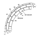
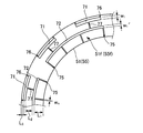
- FIG. 4A shows the friction surface shape of the outer friction surface
- FIG. 4B The friction surface shape of the inner friction surface is shown.
- lock-up clutch and the fluid transmission device with a lock-up mechanism of the present embodiment are substantially the same as those in the first embodiment except for the friction surface shape (groove pattern shape). Will be described using the reference numerals of corresponding members in FIGS. 1, 2, 3A and 3B.
- the first friction material 51 and the second friction material 55 form outer friction surfaces 51 f and 55 f having relatively small areas
- 53 and 54 form inner friction surfaces 52f, 53f and 54f having relatively large areas.
- the first friction material 51 and the second friction material 55 are formed with at least one, for example, a plurality of arc-shaped circumferential grooves 71 and 72 extending in the circumferential direction on the respective friction surface side portions.
- the third friction members 52, 53, 54 are formed with at least one, for example, a plurality of arc-shaped circumferential grooves 73, 74 extending in the circumferential direction in the respective friction surface side portions.
- These circumferential grooves 71, 72, 73, 74 are first circumferential grooves 71, 72 (first circumferential direction) formed in the first friction material 51 and the second friction material 55 and having a relatively large groove area. Groove) and second circumferential grooves 73 and 74 (second circumferential grooves) formed in the third friction members 52, 53 and 54 and having a relatively small groove area.
- first circumferential grooves 71 and 72 are a plurality of different diameter groove portions located on a plurality of circumferences having different radii, and the radius of one first circumferential groove 71 is the other of the second circumferential grooves 71 and 72. It is larger than the radius of one circumferential groove 72.
- second circumferential grooves 73 and 74 are also a plurality of different diameter groove portions located on a plurality of circumferences having different radii, and the radius of one second circumferential groove 73 is the other second. It is larger than the radius of the circumferential groove 74.
- the first circumferential groove 71 has the same radius as the second circumferential groove 73, and the first circumferential groove 72 has the same radius as the second circumferential groove 74. is doing. Furthermore, the groove widths w1 and w1 ′ of the first circumferential grooves 71 and 72 are larger than the groove widths w2 and w2 ′ of the second circumferential grooves 73 and 74, and the first circumferential grooves 71, 72 and the second circumferential grooves 73 and 74 have a groove depth equal to or less than the thickness Tp of the corresponding friction material 51-55.
- first circumferential grooves 71 having a large radius are, for example, arc grooves having a center angle of 15 degrees, and are spaced apart from each other by a constant angular interval.
- the second circumferential grooves 73 and 74 having a small radius are arc grooves having a central angle of 45 degrees, for example, and are spaced at a constant angular interval of about 1/3 of the central angle.
- the respective friction surface side portions of the first friction material 51, the third friction materials 52, 53, 54, and the second friction material 55 extend in the radial direction (radial direction).
- a plurality of radial narrow grooves 75, 76, 77 that are spaced apart at equal intervals in the circumferential direction with a preset spacing angle formed therebetween.
- These narrow grooves 75-77 include a plurality of first narrow grooves 75 positioned radially inward with respect to the first circumferential grooves 71, 72 and the second circumferential grooves 73, 74, and a first circumferential direction.
- a plurality of second narrow grooves 76 located radially outward with respect to the grooves 71 and 72 and the second circumferential grooves 73 and 74, and the first circumferential grooves 71 and 72 and the second circumferential grooves 73 and 74
- a plurality of third narrow grooves 77 located between the two.
- the spacing angles of the plurality of first narrow grooves 75 and the plurality of second narrow grooves 76 are set to be equal to each other, and the spacing angles of the plurality of third narrow grooves 77 are The spacing angle is set to be larger than both the spacing angle of the plurality of first narrow grooves 75 and the spacing angle of the plurality of second narrow grooves 76.
- the plurality of first narrow grooves 75 and the plurality of second narrow grooves 76 are in the same phase, and the plurality of third narrow grooves 77 are in a phase different from that of the plurality of first narrow grooves 75 and the plurality of second narrow grooves 76. Is arranged in.
- first narrow groove 75 located at the innermost position in the radial direction has the maximum length L1 or L1 ′
- the second fine groove 76 positioned at the outermost position in the radial direction has the minimum length L3 or L3 ′
- the third narrow groove 77 located between the first narrow groove 75 and the second narrow groove 76 in the radial direction is shorter than the maximum lengths L1 and L1 ′ and is longer than the minimum lengths L3 and L3 ′. L2 and L2 ′.
- each of the plurality of narrow grooves 75-77 is the groove of at least the first circumferential groove 71, 72 out of the first circumferential groove 71, 72 and the second circumferential groove 73, 74. It is sufficiently smaller than the widths w1 and w1 ′. Further, the groove depths of the plurality of narrow grooves 75-77 are smaller than the thickness Tp (see FIG. 2) of the corresponding friction materials 51-55.
- the outer friction surfaces 51f and 55f that rub against the front cover 15 or the lock-up piston 31 are easy to radiate heat, but the friction area is narrow and the surface pressure is increased, so that the heat generation amount per unit area increases.
- the inner friction surfaces 52f-54f that rub against the torque transmission plates 35, 36 are difficult to dissipate heat, but the friction area is large and the surface pressure is reduced, so that the heat generation amount per unit area is reduced.
- the temperatures of the first friction material 51, the third friction material 52-54 and the second friction material 55 forming the multi-surface friction surfaces 51f-55f are made uniform, and the multi-surface friction surfaces 51f-55f It is possible to prevent the temperature during frictional heat generation due to slip control or the like from becoming unbalanced.
- the first friction material 51 and the second friction material 55 have the first circumferential grooves 71 and 72 having a relatively large area, and the third friction materials 52, 53, and 54 Since the second circumferential grooves 73 and 74 having a small area are formed, it is difficult from the production side to sufficiently eliminate the undulations of the engagement surfaces 15e and 31e of the front cover 15 and the lockup piston 31. Even if it exists, generation
- the circumferential groove is a circumferential groove or a plurality of arc-shaped grooves arranged on the same circumference.
- the circumferential groove referred to in the present invention is a circle having a constant radius. It is not limited to a circumferential groove or an arcuate groove, and may be a noncircular or noncircular arc having a different radius depending on the position in the circumferential direction.
- the circumferential groove has a certain angular range in the circumferential direction (for example, the number of grooves in the circumferential groove ⁇ the central angle of each circumferential groove exceeds 180 degrees, even if the circumferential groove is oriented away from the circumference or arc of a certain radius.
- the groove may be a continuous groove over a range, and does not necessarily have a fixed orientation.
- the plurality of radial narrow grooves 65, 66, 67 are spaced apart at equal intervals in the circumferential direction, but needless to say, they may be unevenly spaced. .
- the four plates 32, 33, 35, and 36 for torque transmission are provided to form the five friction surfaces 51f-55f. If at least three friction surfaces are formed by the first friction material, the second friction material that rubs against the lock-up piston, or the third friction material that rubs against the torque transmission plate, the number of plates Is not questioned.
- the lock-up clutch according to the present invention makes the temperature of the first to third friction materials forming three or more friction surfaces uniform, and generates frictional heat by slip control or the like between the multiple friction surfaces. It is possible to provide a lock-up clutch that can prevent the temperature of the time from becoming unbalanced and can improve the accuracy of the lock-up control including the slip control. It is useful for all lockup clutches used as a lockup mechanism for fluid transmission devices such as the above.
Landscapes
- Engineering & Computer Science (AREA)
- General Engineering & Computer Science (AREA)
- Mechanical Engineering (AREA)
- Mechanical Operated Clutches (AREA)
- Control Of Fluid Gearings (AREA)
Abstract
Description
図1および図2に、本発明の第1実施形態に係るロックアップクラッチとそれを備えたロックアップ機構付流体伝動装置の概略構成を示している。なお、本実施形態のロックアップクラッチおよびロックアップ機構付流体伝動装置は、フロントエンジン・リヤドライブタイプの車両に搭載されるもので、図中の右方側が車両後方側、図中の左方側が車両前方側である。勿論、本発明のロックアップクラッチおよびそれを備えたロックアップ機構付流体伝動装置は、他の駆動方式の車両に搭載されるものであってもよい。
図4Aおよび図4Bは、本発明の第2実施形態に係るロックアップクラッチの摩擦材の摩擦面形状の説明図であり、図4Aにその外側の摩擦面の摩擦面形状を示し、図4Bにその内側の摩擦面の摩擦面形状を示している。
12 トルクコンバータ
13 ロックアップクラッチ
14 ダンパ装置
15 フロントカバー
15e、31e 係合面
21 ポンプインペラ
22 タービンランナ
23 ステータ
25 タービンハブ(変速機入力軸側の回転部材)
27 ステータシャフト
31 ロックアップピストン
32、33 第1プレート(トルク伝達用のプレート)
35、36 第2プレート(トルク伝達用のプレート)
51 第1摩擦材(摩擦材)
51f、52f、53f、54f、55f 摩擦面
52、53、54 第3摩擦材(摩擦材)
55 第2摩擦材(摩擦材)
56 油路
58 係合側の油室
59 係合解除側の油室
61、62 第1の円周方向溝(円周方向溝、第1周方向溝、複数の異径溝部)
63、64 第2の円周方向溝(円周方向溝、第2周方向溝、複数の異径溝部)
65、75 第1細溝(細溝)
66、76 第2細溝(細溝)
67、77 第3細溝(細溝)
71、72 第1の周方向溝(周方向溝、第1周方向溝、複数の異径溝部)
73、74 第2の周方向溝(周方向溝、第2周方向溝、複数の異径溝部)
101 変速機入力軸
101a 油穴
L1、L1´ 最大長さ
L2、L2´ 中間長さ
L3、L3´ 最小長さ
w1、w1´、w2、w2´ 溝幅
Claims (8)
- エンジン側の回転部材に連結されるフロントカバーと、変速機入力軸側の回転部材にダンパ装置を介しトルク伝達可能に係合するロックアップピストンと、前記フロントカバーおよび前記ロックアップピストンの間に介在するトルク伝達用の複数のプレートと、前記フロントカバー、前記ロックアップピストンおよび前記複数のプレートの間に3面以上の摩擦面を形成する略環状の複数の摩擦材と、を備えたロックアップクラッチであって、
前記複数の摩擦材が、前記フロントカバーに対し摩擦する第1摩擦材と、前記ロックアップピストンに対し摩擦する第2摩擦材と、前記複数のプレートのいずれかに対し摩擦する第3摩擦材と、によって構成され、
前記3面以上の摩擦面が、前記第1摩擦材および前記第2摩擦材のそれぞれによって形成される面積の小さい外側の摩擦面と、前記第3摩擦材によって形成される面積の大きい内側の摩擦面と、によって構成されていることを特徴とするロックアップクラッチ。 - 前記第1摩擦材、前記第2摩擦材および前記第3摩擦材のそれぞれの摩擦面側部分に、周方向に延びる少なくとも1つの周方向溝が形成されるとともに、
前記周方向溝が、前記第1摩擦材および前記第2摩擦材に形成される面積の大きい第1周方向溝と、前記第3摩擦材に形成される面積の小さい第2周方向溝と、によって構成されていることを特徴とする請求項1に記載のロックアップクラッチ。 - 前記第1周方向溝が、前記第2周方向溝と同一の半径を有するとともに、前記第1周方向溝の溝幅が、前記第2周方向溝の溝幅より大きくなっていることを特徴とする請求項2に記載のロックアップクラッチ。
- 前記第1周方向溝および前記第2周方向溝が、それぞれ半径の異なる複数の円周上に位置する複数の異径溝部で構成されていることを特徴とする請求項3に記載のロックアップクラッチ。
- 前記第1摩擦材、前記第2摩擦材および前記第3摩擦材のそれぞれの摩擦面側部分に、それぞれ半径方向に延びるとともに周方向に離間する複数の細溝が形成され、
前記複数の細溝のそれぞれの溝幅が、前記第1周方向溝の溝幅より小さくなっていることを特徴とする請求項1ないし請求項4のうちいずれか1の請求項に記載のロックアップクラッチ。 - 前記細溝が、前記周方向に等間隔に離間していることを特徴とする請求項5に記載のロックアップクラッチ。
- 前記細溝が、前記周方向溝に対し半径方向内側に位置する第1細溝と、前記周方向溝に対し半径方向外側に位置する第2細溝と、によって構成されていることを特徴とする請求項5または請求項6に記載のロックアップクラッチ。
- 前記複数の摩擦材が、前記複数のプレートに固着されていることを特徴とする請求項1ないし請求項7のうちいずれか1の請求項に記載のロックアップクラッチ。
Priority Applications (4)
| Application Number | Priority Date | Filing Date | Title |
|---|---|---|---|
| US13/582,620 US8657088B2 (en) | 2010-03-12 | 2010-03-12 | Lock-up clutch |
| JP2012504159A JP5333651B2 (ja) | 2010-03-12 | 2010-03-12 | ロックアップクラッチ |
| PCT/JP2010/001785 WO2011111117A1 (ja) | 2010-03-12 | 2010-03-12 | ロックアップクラッチ |
| CN201080065396.8A CN102812268B (zh) | 2010-03-12 | 2010-03-12 | 锁止离合器 |
Applications Claiming Priority (1)
| Application Number | Priority Date | Filing Date | Title |
|---|---|---|---|
| PCT/JP2010/001785 WO2011111117A1 (ja) | 2010-03-12 | 2010-03-12 | ロックアップクラッチ |
Publications (1)
| Publication Number | Publication Date |
|---|---|
| WO2011111117A1 true WO2011111117A1 (ja) | 2011-09-15 |
Family
ID=44562966
Family Applications (1)
| Application Number | Title | Priority Date | Filing Date |
|---|---|---|---|
| PCT/JP2010/001785 Ceased WO2011111117A1 (ja) | 2010-03-12 | 2010-03-12 | ロックアップクラッチ |
Country Status (4)
| Country | Link |
|---|---|
| US (1) | US8657088B2 (ja) |
| JP (1) | JP5333651B2 (ja) |
| CN (1) | CN102812268B (ja) |
| WO (1) | WO2011111117A1 (ja) |
Families Citing this family (13)
| Publication number | Priority date | Publication date | Assignee | Title |
|---|---|---|---|---|
| KR101339234B1 (ko) * | 2011-12-09 | 2013-12-09 | 현대자동차 주식회사 | 댐퍼 클러치 제어 방법 |
| JP5900469B2 (ja) * | 2013-11-22 | 2016-04-06 | トヨタ自動車株式会社 | 振動低減装置 |
| JP2016001004A (ja) * | 2014-06-11 | 2016-01-07 | Nskワーナー株式会社 | 摩擦板及び摩擦板を備えた湿式多板クラッチ |
| JP2017096366A (ja) * | 2015-11-20 | 2017-06-01 | ジヤトコ株式会社 | ロックアップクラッチ |
| JP6458780B2 (ja) * | 2016-07-21 | 2019-01-30 | トヨタ自動車株式会社 | 車両用動力伝達装置の制御装置 |
| DE102016014725A1 (de) * | 2016-12-09 | 2018-06-14 | Daimler Ag | Drehmomentwandlervorrichtung, insbesondere für einen Antriebsstrang eines Kraftfahrzeugs |
| US20190376591A1 (en) * | 2017-03-27 | 2019-12-12 | Aisin Aw Co., Ltd. | Fluid transmission device |
| DE102017128403A1 (de) * | 2017-11-30 | 2019-06-06 | Schaeffler Technologies AG & Co. KG | Reibteil |
| US10850352B2 (en) | 2017-12-21 | 2020-12-01 | GM Global Technology Operations LLC | Method of laser cutting grooves in a friction clutch plate |
| DE102019116682A1 (de) * | 2019-06-19 | 2020-12-24 | Hoerbiger Antriebstechnik Holding Gmbh | Endlamelle einer Lamellenkupplung, Baugruppe sowie Verfahren zur Herstellung einer Baugruppe |
| CN111486183B (zh) * | 2020-04-20 | 2021-09-21 | 北京理工大学 | 一种湿式多片式换挡离合器 |
| DE102020212529A1 (de) | 2020-10-05 | 2022-04-07 | Zf Friedrichshafen Ag | Hydrodynamischer Drehmomentwandler mit einer Überbrückungskupplung |
| KR102766527B1 (ko) * | 2021-12-31 | 2025-02-12 | 주식회사 카펙발레오 | 차량용 토크 컨버터 |
Citations (3)
| Publication number | Priority date | Publication date | Assignee | Title |
|---|---|---|---|---|
| JPH07145858A (ja) * | 1993-11-25 | 1995-06-06 | Nissan Motor Co Ltd | 多板ロックアップクラッチ付トルクコンバータ |
| JP2002242954A (ja) * | 2001-02-14 | 2002-08-28 | Aisin Aw Co Ltd | 摩擦板 |
| JP2006342819A (ja) * | 2005-06-07 | 2006-12-21 | Mazda Motor Corp | 変速機のクラッチ構造 |
Family Cites Families (11)
| Publication number | Priority date | Publication date | Assignee | Title |
|---|---|---|---|---|
| US5101953A (en) * | 1986-09-16 | 1992-04-07 | Borg-Warner Automotive Transmission & Engine Components Corporation | High capacity viscous pumping groove pattern for a wet clutch |
| US4995500A (en) * | 1986-09-16 | 1991-02-26 | Borg-Warner Corporation | Groove pattern for high thermal capacity wet clutch |
| JPH09257057A (ja) | 1996-03-21 | 1997-09-30 | Fuji Heavy Ind Ltd | 多板摩擦係合装置 |
| JPH09287622A (ja) | 1996-04-19 | 1997-11-04 | Fuji Heavy Ind Ltd | 多板摩擦係合装置 |
| FR2751386B1 (fr) * | 1996-07-18 | 1998-09-18 | Valeo | Garniture de friction pour un embrayage comportant un reseau de rainures |
| DE10109493B4 (de) * | 2001-02-28 | 2015-09-24 | Zf Friedrichshafen Ag | Hydrodynamische Kopplungseinrichtung |
| JP2004332779A (ja) | 2003-05-01 | 2004-11-25 | Exedy Corp | 流体式トルク伝達装置のロックアップ装置 |
| JP2006037991A (ja) | 2004-07-22 | 2006-02-09 | Aisin Aw Co Ltd | トルクコンバータ用のロックアップ機構 |
| JP2007051759A (ja) * | 2005-07-20 | 2007-03-01 | Nsk Warner Kk | 湿式多板クラッチ用のフリクションプレート |
| JP2007292223A (ja) * | 2006-04-26 | 2007-11-08 | F C C:Kk | ロックアップクラッチ |
| JP2008215498A (ja) | 2007-03-05 | 2008-09-18 | Nsk Warner Kk | 湿式多板摩擦係合装置 |
-
2010
- 2010-03-12 JP JP2012504159A patent/JP5333651B2/ja not_active Expired - Fee Related
- 2010-03-12 WO PCT/JP2010/001785 patent/WO2011111117A1/ja not_active Ceased
- 2010-03-12 US US13/582,620 patent/US8657088B2/en not_active Expired - Fee Related
- 2010-03-12 CN CN201080065396.8A patent/CN102812268B/zh not_active Expired - Fee Related
Patent Citations (3)
| Publication number | Priority date | Publication date | Assignee | Title |
|---|---|---|---|---|
| JPH07145858A (ja) * | 1993-11-25 | 1995-06-06 | Nissan Motor Co Ltd | 多板ロックアップクラッチ付トルクコンバータ |
| JP2002242954A (ja) * | 2001-02-14 | 2002-08-28 | Aisin Aw Co Ltd | 摩擦板 |
| JP2006342819A (ja) * | 2005-06-07 | 2006-12-21 | Mazda Motor Corp | 変速機のクラッチ構造 |
Also Published As
| Publication number | Publication date |
|---|---|
| JP5333651B2 (ja) | 2013-11-06 |
| CN102812268B (zh) | 2014-05-28 |
| CN102812268A (zh) | 2012-12-05 |
| US20120325614A1 (en) | 2012-12-27 |
| JPWO2011111117A1 (ja) | 2013-06-27 |
| US8657088B2 (en) | 2014-02-25 |
Similar Documents
| Publication | Publication Date | Title |
|---|---|---|
| JP5333651B2 (ja) | ロックアップクラッチ | |
| US5918713A (en) | Wet friction plate, wet power transmitting and interrupting mechanism, wet clutch and lockup clutch | |
| JP5067512B2 (ja) | ロックアップクラッチ機構 | |
| US10260610B2 (en) | Torque converter for a vehicle | |
| JP2011089577A (ja) | トルクコンバータ | |
| CN105299111A (zh) | 摩擦片及具备摩擦片的湿式多片离合器 | |
| CN103459874B (zh) | 摩擦部件、离合器片、离合器装置及扭矩转换器 | |
| JP4073749B2 (ja) | 流体式トルク伝達装置のロックアップ装置 | |
| JP2012215222A (ja) | クラッチ装置およびそれを備えた流体伝動装置 | |
| JP6173814B2 (ja) | クラッチ | |
| JP6426026B2 (ja) | 流体継手 | |
| JP7051272B2 (ja) | 摩擦締結装置 | |
| US7481305B2 (en) | Lock-up mechanism for torque converter | |
| JP2007333074A (ja) | 流体伝動装置と出力部材との接続構造ならびにこれに用いる出力部材 | |
| JP2000266079A (ja) | 湿式摩擦部材及び摩擦ディスク | |
| JP5670668B2 (ja) | 湿式摩擦板 | |
| JP2008138797A (ja) | ロックアップ装置およびそれを備えた流体式トルク伝達装置 | |
| JP6194834B2 (ja) | 自動変速機 | |
| JP2008190561A (ja) | トルクコンバータ | |
| JP7326046B2 (ja) | 流体継手及びトルクコンバータ | |
| KR20080026844A (ko) | 토크 컨버터의 록 업 클러치 | |
| JP6060929B2 (ja) | 自動変速機 | |
| JPH09189351A (ja) | 流体伝動装置のロックアップクラッチ装置 | |
| JP2018028338A (ja) | トルクコンバータ | |
| JP6328178B2 (ja) | 変速ユニット |
Legal Events
| Date | Code | Title | Description |
|---|---|---|---|
| WWE | Wipo information: entry into national phase |
Ref document number: 201080065396.8 Country of ref document: CN |
|
| 121 | Ep: the epo has been informed by wipo that ep was designated in this application |
Ref document number: 10847351 Country of ref document: EP Kind code of ref document: A1 |
|
| WWE | Wipo information: entry into national phase |
Ref document number: 2012504159 Country of ref document: JP |
|
| WWE | Wipo information: entry into national phase |
Ref document number: 13582620 Country of ref document: US |
|
| NENP | Non-entry into the national phase |
Ref country code: DE |
|
| 122 | Ep: pct application non-entry in european phase |
Ref document number: 10847351 Country of ref document: EP Kind code of ref document: A1 |