WO2011105331A1 - エッチング方法及び装置 - Google Patents
エッチング方法及び装置 Download PDFInfo
- Publication number
- WO2011105331A1 WO2011105331A1 PCT/JP2011/053704 JP2011053704W WO2011105331A1 WO 2011105331 A1 WO2011105331 A1 WO 2011105331A1 JP 2011053704 W JP2011053704 W JP 2011053704W WO 2011105331 A1 WO2011105331 A1 WO 2011105331A1
- Authority
- WO
- WIPO (PCT)
- Prior art keywords
- substrate
- temperature
- processed
- processing
- gas
- Prior art date
Links
- 238000005530 etching Methods 0.000 title claims abstract description 85
- 238000000034 method Methods 0.000 title claims abstract description 35
- 239000000758 substrate Substances 0.000 claims abstract description 161
- XLYOFNOQVPJJNP-UHFFFAOYSA-N water Substances O XLYOFNOQVPJJNP-UHFFFAOYSA-N 0.000 claims abstract description 89
- KRHYYFGTRYWZRS-UHFFFAOYSA-N Fluorane Chemical compound F KRHYYFGTRYWZRS-UHFFFAOYSA-N 0.000 claims abstract description 76
- 238000009833 condensation Methods 0.000 claims abstract description 65
- 230000005494 condensation Effects 0.000 claims abstract description 65
- 229910000040 hydrogen fluoride Inorganic materials 0.000 claims abstract description 60
- XUIMIQQOPSSXEZ-UHFFFAOYSA-N Silicon Chemical compound [Si] XUIMIQQOPSSXEZ-UHFFFAOYSA-N 0.000 claims abstract description 17
- 239000000463 material Substances 0.000 claims abstract description 17
- 229910052710 silicon Inorganic materials 0.000 claims abstract description 17
- 239000010703 silicon Substances 0.000 claims abstract description 17
- 238000012545 processing Methods 0.000 claims description 243
- 239000007789 gas Substances 0.000 claims description 142
- 238000007664 blowing Methods 0.000 claims description 38
- 239000011521 glass Substances 0.000 abstract description 23
- 239000002994 raw material Substances 0.000 description 21
- YCKRFDGAMUMZLT-UHFFFAOYSA-N Fluorine atom Chemical compound [F] YCKRFDGAMUMZLT-UHFFFAOYSA-N 0.000 description 20
- 229910052731 fluorine Inorganic materials 0.000 description 20
- 239000011737 fluorine Substances 0.000 description 20
- 230000032258 transport Effects 0.000 description 14
- 239000000203 mixture Substances 0.000 description 13
- 238000006243 chemical reaction Methods 0.000 description 10
- 238000010438 heat treatment Methods 0.000 description 10
- 238000007788 roughening Methods 0.000 description 10
- 230000015572 biosynthetic process Effects 0.000 description 8
- 239000012159 carrier gas Substances 0.000 description 7
- 239000007788 liquid Substances 0.000 description 7
- 238000004381 surface treatment Methods 0.000 description 7
- 239000011347 resin Substances 0.000 description 6
- 229920005989 resin Polymers 0.000 description 6
- 239000004065 semiconductor Substances 0.000 description 6
- 238000009826 distribution Methods 0.000 description 5
- 229910052739 hydrogen Inorganic materials 0.000 description 5
- 238000012546 transfer Methods 0.000 description 5
- XKRFYHLGVUSROY-UHFFFAOYSA-N Argon Chemical compound [Ar] XKRFYHLGVUSROY-UHFFFAOYSA-N 0.000 description 4
- 229910004298 SiO 2 Inorganic materials 0.000 description 4
- 230000007423 decrease Effects 0.000 description 4
- 238000005259 measurement Methods 0.000 description 4
- 229910052751 metal Inorganic materials 0.000 description 4
- 239000002184 metal Substances 0.000 description 4
- -1 polytetrafluoroethylene Polymers 0.000 description 4
- 229920001343 polytetrafluoroethylene Polymers 0.000 description 4
- 239000004810 polytetrafluoroethylene Substances 0.000 description 4
- 229910052782 aluminium Inorganic materials 0.000 description 3
- XAGFODPZIPBFFR-UHFFFAOYSA-N aluminium Chemical compound [Al] XAGFODPZIPBFFR-UHFFFAOYSA-N 0.000 description 3
- 239000007864 aqueous solution Substances 0.000 description 3
- 229910052786 argon Inorganic materials 0.000 description 3
- 239000000470 constituent Substances 0.000 description 3
- 238000001816 cooling Methods 0.000 description 3
- 238000004519 manufacturing process Methods 0.000 description 3
- 239000012071 phase Substances 0.000 description 3
- TXEYQDLBPFQVAA-UHFFFAOYSA-N tetrafluoromethane Chemical compound FC(F)(F)F TXEYQDLBPFQVAA-UHFFFAOYSA-N 0.000 description 3
- IJGRMHOSHXDMSA-UHFFFAOYSA-N Atomic nitrogen Chemical compound N#N IJGRMHOSHXDMSA-UHFFFAOYSA-N 0.000 description 2
- CBENFWSGALASAD-UHFFFAOYSA-N Ozone Chemical compound [O-][O+]=O CBENFWSGALASAD-UHFFFAOYSA-N 0.000 description 2
- 150000001875 compounds Chemical class 0.000 description 2
- 239000011261 inert gas Substances 0.000 description 2
- 239000007791 liquid phase Substances 0.000 description 2
- 238000012986 modification Methods 0.000 description 2
- 230000004048 modification Effects 0.000 description 2
- 238000003860 storage Methods 0.000 description 2
- BZHJMEDXRYGGRV-UHFFFAOYSA-N Vinyl chloride Chemical compound ClC=C BZHJMEDXRYGGRV-UHFFFAOYSA-N 0.000 description 1
- 230000004913 activation Effects 0.000 description 1
- 238000004380 ashing Methods 0.000 description 1
- QVGXLLKOCUKJST-UHFFFAOYSA-N atomic oxygen Chemical compound [O] QVGXLLKOCUKJST-UHFFFAOYSA-N 0.000 description 1
- 230000005587 bubbling Effects 0.000 description 1
- 238000004140 cleaning Methods 0.000 description 1
- 239000002826 coolant Substances 0.000 description 1
- 238000000354 decomposition reaction Methods 0.000 description 1
- 230000003247 decreasing effect Effects 0.000 description 1
- 238000009792 diffusion process Methods 0.000 description 1
- 238000007865 diluting Methods 0.000 description 1
- 238000010790 dilution Methods 0.000 description 1
- 239000012895 dilution Substances 0.000 description 1
- 230000005284 excitation Effects 0.000 description 1
- 239000001307 helium Substances 0.000 description 1
- 229910052734 helium Inorganic materials 0.000 description 1
- SWQJXJOGLNCZEY-UHFFFAOYSA-N helium atom Chemical compound [He] SWQJXJOGLNCZEY-UHFFFAOYSA-N 0.000 description 1
- 230000001771 impaired effect Effects 0.000 description 1
- 229910052754 neon Inorganic materials 0.000 description 1
- GKAOGPIIYCISHV-UHFFFAOYSA-N neon atom Chemical compound [Ne] GKAOGPIIYCISHV-UHFFFAOYSA-N 0.000 description 1
- 229910052757 nitrogen Inorganic materials 0.000 description 1
- 229910052756 noble gas Inorganic materials 0.000 description 1
- 150000002835 noble gases Chemical class 0.000 description 1
- 230000003287 optical effect Effects 0.000 description 1
- 230000001590 oxidative effect Effects 0.000 description 1
- 239000001301 oxygen Substances 0.000 description 1
- 229910052760 oxygen Inorganic materials 0.000 description 1
- 238000009832 plasma treatment Methods 0.000 description 1
- 239000007787 solid Substances 0.000 description 1
- 229910052724 xenon Inorganic materials 0.000 description 1
- FHNFHKCVQCLJFQ-UHFFFAOYSA-N xenon atom Chemical compound [Xe] FHNFHKCVQCLJFQ-UHFFFAOYSA-N 0.000 description 1
Images


Classifications
-
- H—ELECTRICITY
- H01—ELECTRIC ELEMENTS
- H01L—SEMICONDUCTOR DEVICES NOT COVERED BY CLASS H10
- H01L21/00—Processes or apparatus adapted for the manufacture or treatment of semiconductor or solid state devices or of parts thereof
- H01L21/02—Manufacture or treatment of semiconductor devices or of parts thereof
- H01L21/04—Manufacture or treatment of semiconductor devices or of parts thereof the devices having potential barriers, e.g. a PN junction, depletion layer or carrier concentration layer
- H01L21/18—Manufacture or treatment of semiconductor devices or of parts thereof the devices having potential barriers, e.g. a PN junction, depletion layer or carrier concentration layer the devices having semiconductor bodies comprising elements of Group IV of the Periodic Table or AIIIBV compounds with or without impurities, e.g. doping materials
- H01L21/30—Treatment of semiconductor bodies using processes or apparatus not provided for in groups H01L21/20 - H01L21/26
- H01L21/302—Treatment of semiconductor bodies using processes or apparatus not provided for in groups H01L21/20 - H01L21/26 to change their surface-physical characteristics or shape, e.g. etching, polishing, cutting
- H01L21/306—Chemical or electrical treatment, e.g. electrolytic etching
- H01L21/3065—Plasma etching; Reactive-ion etching
-
- H—ELECTRICITY
- H01—ELECTRIC ELEMENTS
- H01L—SEMICONDUCTOR DEVICES NOT COVERED BY CLASS H10
- H01L21/00—Processes or apparatus adapted for the manufacture or treatment of semiconductor or solid state devices or of parts thereof
- H01L21/67—Apparatus specially adapted for handling semiconductor or electric solid state devices during manufacture or treatment thereof; Apparatus specially adapted for handling wafers during manufacture or treatment of semiconductor or electric solid state devices or components ; Apparatus not specifically provided for elsewhere
- H01L21/677—Apparatus specially adapted for handling semiconductor or electric solid state devices during manufacture or treatment thereof; Apparatus specially adapted for handling wafers during manufacture or treatment of semiconductor or electric solid state devices or components ; Apparatus not specifically provided for elsewhere for conveying, e.g. between different workstations
- H01L21/67739—Apparatus specially adapted for handling semiconductor or electric solid state devices during manufacture or treatment thereof; Apparatus specially adapted for handling wafers during manufacture or treatment of semiconductor or electric solid state devices or components ; Apparatus not specifically provided for elsewhere for conveying, e.g. between different workstations into and out of processing chamber
- H01L21/6776—Continuous loading and unloading into and out of a processing chamber, e.g. transporting belts within processing chambers
-
- C—CHEMISTRY; METALLURGY
- C03—GLASS; MINERAL OR SLAG WOOL
- C03C—CHEMICAL COMPOSITION OF GLASSES, GLAZES OR VITREOUS ENAMELS; SURFACE TREATMENT OF GLASS; SURFACE TREATMENT OF FIBRES OR FILAMENTS MADE FROM GLASS, MINERALS OR SLAGS; JOINING GLASS TO GLASS OR OTHER MATERIALS
- C03C15/00—Surface treatment of glass, not in the form of fibres or filaments, by etching
-
- H—ELECTRICITY
- H01—ELECTRIC ELEMENTS
- H01J—ELECTRIC DISCHARGE TUBES OR DISCHARGE LAMPS
- H01J37/00—Discharge tubes with provision for introducing objects or material to be exposed to the discharge, e.g. for the purpose of examination or processing thereof
- H01J37/32—Gas-filled discharge tubes
- H01J37/32009—Arrangements for generation of plasma specially adapted for examination or treatment of objects, e.g. plasma sources
- H01J37/32018—Glow discharge
-
- H—ELECTRICITY
- H01—ELECTRIC ELEMENTS
- H01J—ELECTRIC DISCHARGE TUBES OR DISCHARGE LAMPS
- H01J37/00—Discharge tubes with provision for introducing objects or material to be exposed to the discharge, e.g. for the purpose of examination or processing thereof
- H01J37/32—Gas-filled discharge tubes
- H01J37/32431—Constructional details of the reactor
- H01J37/32733—Means for moving the material to be treated
- H01J37/32752—Means for moving the material to be treated for moving the material across the discharge
- H01J37/32761—Continuous moving
-
- H—ELECTRICITY
- H01—ELECTRIC ELEMENTS
- H01L—SEMICONDUCTOR DEVICES NOT COVERED BY CLASS H10
- H01L21/00—Processes or apparatus adapted for the manufacture or treatment of semiconductor or solid state devices or of parts thereof
- H01L21/67—Apparatus specially adapted for handling semiconductor or electric solid state devices during manufacture or treatment thereof; Apparatus specially adapted for handling wafers during manufacture or treatment of semiconductor or electric solid state devices or components ; Apparatus not specifically provided for elsewhere
- H01L21/67005—Apparatus not specifically provided for elsewhere
- H01L21/67011—Apparatus for manufacture or treatment
- H01L21/67017—Apparatus for fluid treatment
- H01L21/67063—Apparatus for fluid treatment for etching
- H01L21/67075—Apparatus for fluid treatment for etching for wet etching
- H01L21/6708—Apparatus for fluid treatment for etching for wet etching using mainly spraying means, e.g. nozzles
-
- H—ELECTRICITY
- H01—ELECTRIC ELEMENTS
- H01L—SEMICONDUCTOR DEVICES NOT COVERED BY CLASS H10
- H01L21/00—Processes or apparatus adapted for the manufacture or treatment of semiconductor or solid state devices or of parts thereof
- H01L21/67—Apparatus specially adapted for handling semiconductor or electric solid state devices during manufacture or treatment thereof; Apparatus specially adapted for handling wafers during manufacture or treatment of semiconductor or electric solid state devices or components ; Apparatus not specifically provided for elsewhere
- H01L21/677—Apparatus specially adapted for handling semiconductor or electric solid state devices during manufacture or treatment thereof; Apparatus specially adapted for handling wafers during manufacture or treatment of semiconductor or electric solid state devices or components ; Apparatus not specifically provided for elsewhere for conveying, e.g. between different workstations
- H01L21/67703—Apparatus specially adapted for handling semiconductor or electric solid state devices during manufacture or treatment thereof; Apparatus specially adapted for handling wafers during manufacture or treatment of semiconductor or electric solid state devices or components ; Apparatus not specifically provided for elsewhere for conveying, e.g. between different workstations between different workstations
- H01L21/67706—Mechanical details, e.g. roller, belt
-
- H—ELECTRICITY
- H05—ELECTRIC TECHNIQUES NOT OTHERWISE PROVIDED FOR
- H05H—PLASMA TECHNIQUE; PRODUCTION OF ACCELERATED ELECTRICALLY-CHARGED PARTICLES OR OF NEUTRONS; PRODUCTION OR ACCELERATION OF NEUTRAL MOLECULAR OR ATOMIC BEAMS
- H05H1/00—Generating plasma; Handling plasma
- H05H1/24—Generating plasma
Definitions
- the present invention relates to a method and apparatus for etching a substrate to be processed containing a silicon-containing material, and more particularly to a method and apparatus suitable for etching to the extent that the back surface of a glass substrate is lightly roughened.
- Patent Documents 1 and 2 describe that a processing gas containing hydrogen fluoride (HF) is brought into contact with a glass substrate to etch silicon-containing materials on the surface of the glass substrate.
- the processing gas is formed, for example, by adding water (H 2 O) to a raw material gas containing a fluorine-based compound such as CF 4 and then converting the raw material gas into plasma by atmospheric pressure discharge.
- Hydrogen fluoride is generated by the formation of plasma (formula 1).
- CF 4 + 2H 2 O ⁇ 4HF + CO 2 (Formula 1)
- the etching technique disclosed in the above-mentioned Patent Documents 1 and 2 can be applied to a process of lightly roughening the back surface of a glass substrate, for example.
- the glass substrate is placed on the stage, the main surface (front surface) is surface-treated, and then the glass substrate is easily pulled away from the stage when unloading from the stage. be able to.
- the roughness of the back surface of the glass substrate by the etching process is preferably as small as possible within a range in which the glass substrate can be easily separated from the stage. If the degree of roughening is too large, the glass substrate may be difficult to adhere to the stage during the subsequent surface treatment of the main surface, or the optical characteristics of the glass substrate may be impaired.
- the etching process gas also contacts the main surface of the glass substrate by diffusion. Then, even the main surface is roughened.
- the present invention has been made in view of the circumstances as described above, and its object is to suppress etching of the first surface (for example, the main surface) of the substrate to be processed including silicon-containing materials such as a glass substrate.
- the second surface on the back side is etched while preventing.
- the method of the present invention etches a substrate to be processed that includes a silicon-containing material and has a first surface and a second surface on the back side of the first surface in the vicinity of atmospheric pressure.
- a method Arranging the substrate to be processed in a processing atmosphere containing hydrogen fluoride vapor and water vapor, The temperature of the first surface is adjusted to be higher than the condensation point of hydrogen fluoride and water in the processing atmosphere, and the temperature of the second surface is adjusted to be lower than the condensation point.
- the temperature of the first surface is higher than 0 ° C. to 40 ° C. higher than the condensation point. More preferably, the temperature of the first surface is higher by 5 ° C. to 30 ° C. than the condensation point.
- the temperature of the second surface is preferably 0 ° C. to 10 ° C. lower than the condensation point.
- the temperature of the first surface can be made higher than the condensation point if the first surface is heated slightly.
- the temperature of the second surface can be surely made equal to or lower than the condensation point. Therefore, it is possible to reliably etch the second surface while reliably preventing or suppressing the etching of the first surface.
- the substrate to be processed is carried into the processing space from a carry-in port connected to a processing space where the processing atmosphere exists, the substrate to be processed is carried out from a carry-out port connected to the processing space, and the vicinity of the carry-in port and Gas may be sucked in the vicinity.
- the outside air before the outside air reaches the processing space through the carry-in port or the carry-out port, it can be sucked and exhausted in the vicinity of the carry-in port or the carry-out port, and the outside air can be prevented from flowing into the process space.
- the flow rate and flow rate of the inflowing outside air vary as the substrate to be processed is carried in and out. Even if such fluctuations occur, the above-described suction can prevent outside air from being mixed into the processing atmosphere.
- the gas composition of the processing atmosphere and thus the hydrogen fluoride vapor partial pressure and the water vapor partial pressure, are substantially the same as those of the processing gas itself. Can be kept the same. As a result, it is possible to prevent the second surface from being etched unevenly. Further, even if the humidity of the outside air is higher than the humidity of the processing atmosphere, it is possible to prevent the humidity of the processing atmosphere on the first surface side from increasing, and it is possible to prevent the formation of a condensed layer on the first surface. Therefore, it is possible to avoid etching even the first surface.
- the apparatus of the present invention is an apparatus for etching a substrate to be processed that includes a silicon-containing material and has a first surface and a second surface on the back side of the first surface in a processing space near atmospheric pressure and with a humidity exceeding 0%. Because A blowout nozzle for supplying a processing gas containing at least hydrogen fluoride out of hydrogen fluoride and water into the processing space to contact at least the second surface of the substrate to be processed; Adjusting means for adjusting the temperature of the first surface to be higher than the condensation point of hydrogen fluoride and water in the processing space, and adjusting the temperature of the second surface to be equal to or lower than the condensation point; It is provided with.
- the processing gas from the blowing nozzle is mixed with the processing atmosphere in the processing space. Since the processing gas contains at least hydrogen fluoride of hydrogen fluoride and water, and the humidity of the processing space is more than 0%, the processing atmosphere contains hydrogen fluoride vapor and water vapor. This processing atmosphere comes into contact with the workpiece. At this time, on the second surface of the object to be processed, hydrogen fluoride and water in the processing atmosphere are placed on the second surface of the object to be processed by adjusting the relationship between the condensation point and the temperature of the second surface by the adjusting means. To form a condensed layer of hydrofluoric acid. Therefore, the etching reaction of the silicon-containing material constituting the second surface occurs, and the second surface can be etched (including roughening).
- the adjusting means may control the temperature of the first surface of the substrate to be processed, or may control the temperature of the second surface, and the hydrogen fluoride partial pressure or water vapor content of the processing gas.
- the pressure may be controlled, the water vapor partial pressure of the processing atmosphere in the processing space may be controlled, or the water vapor partial pressure of the outside air flowing into the processing space may be controlled. Also good.
- the adjusting means includes a heater disposed close to the position on the opposite side of the blowing nozzle across the position where the substrate to be processed is disposed in the processing space, and the set temperature of the heater is the condensation
- the temperature is preferably higher than 0 ° C to 60 ° C higher than the above point.
- the temperature of the 1st surface of a to-be-processed substrate can be reliably made high temperature from the condensation point of the hydrogen fluoride and water of process atmosphere.
- the heating temperature of the first surface and thus the amount of heat to be applied to the first surface it is possible to avoid or suppress the transfer of heat to the second surface, and to prevent or suppress the temperature increase of the second surface. Therefore, the temperature of the second surface can be surely made equal to or lower than the condensation point.
- the second surface can be reliably etched while reliably suppressing or preventing the etching of the first surface.
- the set temperature of the heater in consideration of the moving speed. For example, when the moving speed is relatively high, the set temperature is set to be relatively higher than the desired temperature of the first surface. Thereby, the time required for the first surface to reach the desired temperature can be shortened. On the other hand, since the moving speed is relatively high, the process can be completed before the second surface reaches a temperature higher than the condensation point. When the moving speed is relatively low, the set temperature may be substantially the same as the desired temperature. Thereby, it is possible to avoid that the temperature of the substrate to be processed greatly exceeds the desired temperature. On the other hand, if the moving speed is low, the heating time becomes long. By setting the set temperature and the desired temperature to be slightly higher than the condensation point, the temperature of the second surface can be maintained below the condensation point. it can.
- the adjusting means sets the temperature of the second surface to 0 ° C. to 10 ° C. lower than the condensation point.
- the temperature of the first surface exceeds the condensation point. be able to.
- the vicinity of atmospheric pressure refers to a range of 1.013 ⁇ 10 4 to 50.663 ⁇ 10 4 Pa, and considering the ease of pressure adjustment and the simplification of the apparatus configuration, 1.333 ⁇ 10 4 to 10.664 ⁇ 10 4 Pa is preferable, and 9.331 ⁇ 10 4 to 10.9797 ⁇ 10 4 Pa is more preferable.
- the second surface on the back side can be etched while suppressing or preventing the etching of the first surface of the substrate to be processed.
- FIG. 2 is a front sectional view of a processing section of the atmospheric pressure etching apparatus taken along line II-II in FIG. It is side surface sectional drawing which shows the atmospheric pressure etching apparatus which concerns on 2nd Embodiment of this invention.
- FIG. 4 is a front sectional view of the atmospheric pressure etching apparatus according to the second embodiment, taken along line IV-IV in FIG. 3. It is side surface sectional drawing which shows the atmospheric pressure etching apparatus which concerns on 3rd Embodiment of this invention.
- FIG. 2 is a front sectional view of a processing section of the atmospheric pressure etching apparatus taken along line II-II in FIG. It is side surface sectional drawing which shows the atmospheric pressure etching apparatus which concerns on 2nd Embodiment of this invention.
- FIG. 4 is a front sectional view of the atmospheric pressure etching apparatus according to the second embodiment, taken along line IV-IV in FIG. 3. It is side surface sectional drawing which shows the atmospheric pressure etching apparatus which concerns on 3rd Embodiment
- Example 6 is a plan sectional view of a processing section of the atmospheric pressure etching apparatus according to the third embodiment, taken along line VI-VI in FIG. 5. It is a side view which shows the gas flow fluctuation
- Example 1 it is a graph which shows distribution of the substrate width direction of the etching rate of the 1st surface and 2nd surface when heater preset temperature is 25 degreeC. In Example 1, it is a graph which shows distribution of the board
- the substrate 9 to be processed is a glass substrate to be a semiconductor device such as a flat panel display.
- the glass substrate 9 contains a silicon-containing material such as SiO 2 as a main component.
- the thickness of the glass substrate 9 is, for example, about 0.5 mm to 0.7 mm.
- the glass substrate 9 has a rectangular flat plate shape, and has a first surface 9a (main surface) on the front side and a second surface 9b (back surface) on the back side.
- the first surface 9a is a main surface on which various electronic element layers such as an insulating layer, a conductive layer, and a semiconductor layer are to be provided.
- the second surface 9 b is a back surface that is a target of roughening (etching) processing by the atmospheric pressure etching apparatus 1. After roughening the second surface 9b, a surface treatment for forming the various electronic element layers is performed on the first surface 9a.
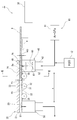
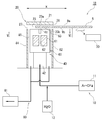
- the atmospheric pressure etching apparatus 1 includes a source gas supply means 10, a processing unit 20, and a transport means 30.
- the source gas supply unit 10 includes a fluorine-based source supply unit 11 and a water addition unit 12.
- the fluorine-based raw material supply unit 11 supplies a raw material gas serving as an etching process gas (etchant).
- the source gas includes a fluorine-containing gas and a carrier gas.
- CF 4 is used as the fluorine-containing gas.
- other PFC perfluorocarbon
- CHF 3 , CH 2 F 2 , CH 3 F may be used HFC (hydrofluorocarbon) etc.
- the carrier gas has a function as a dilution gas for diluting the fluorine-containing gas, a function as a discharge gas for generating plasma discharge described later, and the like.
- An inert gas is preferably used as the carrier gas.
- the inert gas serving as the carrier gas include noble gases such as helium, argon, neon, and xenon, and nitrogen.
- argon (Ar) is used as the carrier gas.
- the flow ratio (CF 4 : Ar) between the fluorine-containing gas and the carrier gas is preferably 1: 1000 to 1:10.
- the carrier gas may be omitted.
- the water addition unit 12 adds water (H 2 O) to the source gas (CF 4 + Ar) and humidifies the source gas. By adjusting the amount of water added, the water vapor partial pressure of the raw material gas, and thus the hydrogen fluoride partial pressure and water vapor partial pressure of the processing gas are adjusted.
- the water addition part 12 is comprised with the humidifier provided with tanks, such as a thermostat, for example. Liquid water is stored in this tank. The raw material gas from the supply part 11 is supplied to the upper part from the water surface of the tank, and is mixed with the saturated water vapor in the upper part. Or you may add water vapor
- the vapor pressure may be adjusted by adjusting the temperature of the tank, thereby adjusting the amount of water added. It is preferable to adjust the water addition amount of the water addition unit 12 and the dew point of the processing gas so as to satisfy the etching performance of the second surface 9b.
- the dew point of the raw material gas before water addition is preferably ⁇ 40 ° C. or lower.
- dew point ⁇ 40 ° C. When dew point ⁇ 40 ° C. is converted to water vapor partial pressure, it is about 0.03 Torr, and when converted to volume concentration, it is about 0.004%, and the amount of water vapor in the raw material gas is almost equal to zero.
- the amount of water in the raw material gas after the addition of water can be calculated from the dew point of the raw material gas before the addition of water and the amount of water vaporized in the water addition unit 12. You may measure the moisture content in the raw material gas after water addition using a Fourier-transform type
- FTIR Fourier-transform type
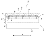
- the processing unit 20 includes a top plate 21, a bottom plate 22, a blowing nozzle 40, and a suction nozzle 50.
- the top plate 21 has a horizontal plate shape.
- the width dimension of the top plate 21 along the direction orthogonal to the paper surface of FIG. 1 (hereinafter referred to as “y direction”) is slightly larger than the width dimension of the substrate 9 to be processed in the y direction.
- the top plate 21 is composed of a plate heater and also serves as a temperature adjusting means described later.
- the housing of the top plate 21, that is, the plate heater 21, is made of metal such as aluminum. It is preferable to provide a resin film having high fluorine resistance and plasma resistance, such as polytetrafluoroethylene, on at least the lower surface of the top plate 21.
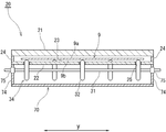
- the bottom plate 22 has a horizontal plate shape and is arranged below the top plate 21 in parallel.
- the width dimension of the bottom plate 22 in the y direction (left and right direction in FIG. 2) is slightly larger than the width dimension of the substrate 9 to be processed in the y direction.
- the bottom plate 22 may be made of a metal such as aluminum, may be made of resin, or may be made of a glass plate. When the bottom plate 22 is made of metal, it is preferable to provide a resin film having high fluorine resistance and plasma resistance, such as polytetrafluoroethylene, on at least the upper surface of the surface.
- the blowing nozzle 40 is disposed at one end (right in FIG. 1) of the processing unit 20 in the left-right direction (hereinafter referred to as “x direction”) in FIG.
- the blowing nozzle 40 is a container shape extended long in ay direction.
- a blowing port 41 is provided on the upper end surface of the blowing nozzle 40.
- the outlet 41 has a slit shape extending in the y direction. The length along the y direction of the outlet 41 is slightly larger than the width dimension along the y direction of the substrate 9 to be processed.
- the blowing nozzle 40 is in contact with one end (right in FIG. 1) of the bottom plate 22 in the x direction.
- the upper end surface of the blowing nozzle 40 is flush with the upper surface of the bottom plate 22.
- One end portion (right in FIG. 1) of the top plate 21 extends to one end side (right in FIG. 1) from the bottom plate 22 and covers the upper side of the blowing nozzle 40.
- a carry-in entrance 26 is formed between one end of the top plate 21 and the blowing nozzle 40.
- the suction nozzle 50 is disposed at the other end portion (left side in FIG. 1) of the processing unit 20 in the x direction.
- the suction nozzle 50 has a container shape extending in the y direction.
- a suction port 51 is opened at the upper end surface of the suction nozzle 50.
- the suction port 51 has a slit shape extending in the y direction.
- the length along the y direction of the suction port 51 is slightly larger than the width dimension along the y direction of the substrate 9 to be processed.
- the suction nozzle 50 is in contact with the other end of the bottom plate 22 in the x direction (left in FIG. 1).
- the upper end surface of the suction nozzle 50 is flush with the upper surface of the bottom plate 22.
- the other end portion (left in FIG. 1) of the top plate 21 extends to the other end side from the bottom plate 22 and covers the upper side of the suction nozzle 50.
- a carry-out port 27 is formed between the other end of the top plate 21 and the suction nozzle 51.
- a processing unit internal space 29 is formed between the upper top plate 21 and the lower constituent units 22, 40, 50 in the processing unit 20.
- a carry-in port 26 is connected to one end portion (right side in FIG. 1) of the processing unit internal space 29 in the x direction.
- a carry-out port 26 is connected to the other end portion (left side in FIG. 1) of the processing portion internal space 29 in the x direction.
- Both end portions in the x direction of the processing unit internal space 29 are connected to a space outside the processing unit 20 via the loading / unloading ports 26 and 27. As shown in FIG. 2, both end portions in the y direction of the processing unit internal space 29 are respectively closed by side walls 24.
- a portion of the processing unit internal space 29 from the position in the x direction of the outlet 41 to the position in the x direction of the suction port 51 constitutes a processing space 23.
- the upper top plate 21, the lower constituent parts 22, 40, 50 and the side walls 24 in the processing part 20 constitute a processing space defining part.
- the processing space 23 is connected to the carry-in port 26 via a processing unit internal space 29 on one end side in the x direction from the blowout port 41.
- the processing space 23 is connected to the carry-out port 27 via the processing portion internal space 29 on the other end side in the x direction from the suction port 51.
- a rectifying unit 42 is provided at the lower part of the blowout nozzle 40. Although detailed illustration is omitted, the rectifying unit 42 includes a chamber or slit extending in the y direction, a row of many small holes arranged in the y direction, and the like.
- the source gas (CF 4 + Ar + H 2 O) after the addition of water is introduced into the rectifying unit 42 and is made uniform in the y direction.
- a plasma generation unit 60 is stored inside the blowing nozzle 40.
- the plasma generation unit 60 includes at least a pair of electrodes 61 and 61. These electrodes 61 and 61 each extend in the y direction.
- a solid dielectric layer (not shown) is provided on the opposing surface of at least one electrode 61.
- a power source (not shown) is connected to one electrode 61.
- the other electrode 61 is electrically grounded.
- a plasma discharge space 62 having a substantially atmospheric pressure is generated between the pair of electrodes 61.
- the discharge space 62 has a slit-like shape that extends in the y direction like the electrode 61.
- the source gas (CF 4 + Ar + H 2 O) is turned into plasma (including decomposition, excitation, activation, radicalization, ionization, etc.).
- a processing gas containing a fluorine-based reaction component such as hydrogen fluoride (HF) or COF 2 is generated (formula 1 or the like).
- HF hydrogen fluoride
- COF 2 further reacts with water and is converted to hydrogen fluoride (Formula 3).
- the addition amount of the water addition unit 12 is set so that almost the entire amount of H 2 O in the raw material gas contributes to the hydrogen fluoride production reaction (Formula 1 and Formula 3). Therefore, the H 2 O content in the processing gas is small enough to be substantially ignored or 0%.
- the processing gas contains undecomposed source gas components (CF 4 , Ar, H 2 O) in addition to the fluorine-based reaction components. This processing gas is blown upward from the blowout port 41. The blow-out flow of the processing gas is uniform in the y direction.
- the suction nozzle 50 is connected to exhaust means such as a suction pump. By driving the exhaust means, the gas in the processing space 23 is sucked into the suction port 51 of the suction nozzle 590 and exhausted.
- the exhaust gas flow rate from the suction nozzle 50 is larger than the supply flow rate of the processing gas from the blowing nozzle 40.
- An amount of outside air (air or the like) corresponding to the difference between the exhaust flow rate and the supply flow rate flows into the processing unit internal space 29 from the carry-in port 26 and the carry-out port 27.
- the outside air from the carry-in port 26 passes through the outlet 41 and flows into the processing space 23.
- the processing atmosphere in the processing space 23 becomes a mixed gas of the outside air flowing in from the carry-in port 26 and the processing gas.
- inflowing outside air refers to outside air flowing into the processing space 23 from the carry-in port 26 unless otherwise specified.
- the inflowing outside air contains moisture and the humidity is at least over 0%.
- the exhaust gas flow rate from the suction nozzle 50 is set to be sufficiently larger than the processing gas supply flow rate, and the inflowing outside air flow rate is set to be sufficiently larger (for example, about 10 times) than the processing gas supply flow rate. Yes. Therefore, coupled with the extremely small water content of the processing gas, the water vapor partial pressure of the processing atmosphere in the processing space 23 is substantially equal to the water vapor partial pressure of the outside air.
- the conveying means 30 includes a roller shaft 31 and a conveying roller 32 provided at the lower part of the processing unit 20.
- a plurality of roller shafts 31 are arranged in parallel at intervals in the x direction with the axis line directed in the width direction y.
- a plurality of transport rollers 32 are provided at intervals in the axial direction y of each roller shaft 31.
- the upper end portion of the conveying roller 32 is passed through the roller hole 25 of the bottom plate 22, protrudes above the upper surface of the bottom plate 22, and faces the processing space 23.
- the amount of protrusion of the transport roller 32 from the upper surface of the bottom plate 22 corresponds to the distance (working distance WD) between the second surface 9b of the substrate 9 to be processed and the outlet 41.
- the transport means 30 transports the substrate 9 to be processed in the direction of arrow a (leftward in FIG. 1) along the x direction while horizontally supporting the substrate 9 to be processed.
- the substrate 9 to be processed is inserted into the processing space 23 from the carry-in entrance 26, passes through the processing space 23, and exits from the carry-out exit 27.
- the conveyance speed of the substrate 9 to be processed by the conveyance means 30 is preferably about 0.1 m / min to 20 m / min.
- the transport unit 30 also serves as a support unit that supports the substrate 9 to be processed and is disposed in the processing space 23.
- the first surface 9a of the substrate 9 to be processed is directed upward, and the second surface 9b is directed downward.
- the atmospheric pressure etching apparatus 1 is provided with adjusting means.
- the adjusting means adjusts the temperature of the first surface 9 a and the second surface 9 b of the substrate 9 to be processed in relation to the condensation point of the mixed system of hydrogen fluoride and water in the processing space 23.
- the top plate 21 is composed of a plate heater as described above, and is provided as a main element of the adjusting means.
- the top plate, that is, the plate heater 21, is disposed on the opposite side of the blowing nozzle 40 across the position where the substrate 9 to be processed is disposed in the processing space 23, and is disposed close to the position.
- the heater 21 can be set in a temperature range from room temperature to about 50 ° C., for example.
- the set temperature of the heater 21 is set according to the humidity of the outside air, the water vapor partial pressure of the processing atmosphere in the processing space 23, the processing gas, and the hydrogen fluoride partial pressure of the processing atmosphere in the processing space 23, and the like.
- a method for light etching the substrate 9 to be processed using the atmospheric pressure etching apparatus 1 configured as described above will be described.
- a predetermined amount of water vapor (H 2 O) is added to the source gas (CF 4 + Ar) from the fluorine-based source supply unit 11 at the water addition unit 12 to obtain a humidified source gas.
- the humidified raw material gas (CF 4 + Ar + H 2 O) is made uniform in the width direction y by the rectifying unit 42 and then converted into plasma by the plasma generating unit 60.
- the process gas which contains hydrogen fluoride at least among hydrogen fluoride and water is produced
- the hydrogen fluoride partial pressure and the water vapor partial pressure of the processing gas can be adjusted by adjusting the amount of water vapor added in the water addition unit 12.
- almost all of the water in the raw material gas is consumed for the production of hydrogen fluoride, and the water vapor partial pressure of the processing gas is substantially zero.
- the temperature of the processing gas is around room temperature.
- This processing gas is blown out from the blowing port 41 and supplied into the processing space 23.
- the gas in the processing space 23 is sucked into the suction nozzle 50 and exhausted.
- This exhaust flow rate is made sufficiently larger than the processing gas supply flow rate. Therefore, a sufficiently larger amount of outside air than the processing gas is caught in the processing space 23 and mixed with the processing gas.
- the water vapor partial pressure of the process atmosphere (mixed gas of process gas and the said inflow external air) in the process space 23 becomes substantially equal to the water vapor partial pressure of external air.
- the hydrogen fluoride partial pressure in the treatment atmosphere is equal to the hydrogen fluoride partial pressure in the treatment gas.
- the condensation points of hydrogen fluoride and water in the treatment atmosphere are determined according to the hydrogen fluoride partial pressure and the water vapor partial pressure of the treatment atmosphere. That is, the critical temperature at which a condensed layer of hydrofluoric acid is generated is determined (FIG. 11).
- the initial temperature of the substrate 9 to be processed is usually room temperature or about 15 ° C. to 35 ° C.
- the initial temperature of the substrate 9 to be processed refers to the temperature of the substrate 9 to be processed immediately before the substrate 9 is carried into the processing unit 23.
- the entire substrate 9 to be processed is at the initial temperature. Therefore, the first surface 9a and the second surface 9b are at the initial temperature.
- the substrate 9 to be processed is inserted into the processing space 23 from the carry-in entrance 26, and from one end side (right in FIG. 1) to the other end side (left in FIG. 1) of the processing space 23 along the direction of arrow a in FIG. Transport to.
- the substrate 9 to be processed is covered above the blowing nozzle 40, and the processing gas blown from the blowing port 41 comes into contact with at least the second surface 9 b of the substrate 9 to be processed. Further, part of the processing gas diffused into the processing space 23 comes into contact with the first surface 9 a of the substrate 9 to be processed.
- the blowing temperature of the processing gas and the initial temperature of the substrate 9 to be processed are both near room temperature, and the temperature difference between them is small. Therefore, the temperature of the substrate 9 to be processed hardly changes depending on the blowing of the processing gas.
- the top plate Prior to loading the substrate 9 to be processed, the top plate, that is, the heater 21 is heated to a set temperature and kept at the set temperature.
- the set temperature of the heater 21 is set higher than the condensation point of hydrogen fluoride and water in the processing atmosphere, and preferably slightly higher than the condensation point.
- the set temperature of the heater 21 is adjusted to be higher than 0 ° C. to about 60 ° C. above the condensation point.
- the heat of the heater 21 is transmitted in a non-contact manner to the first surface 9 a of the substrate 9 to be processed introduced into the processing space 23. Thereby, the 1st surface 9a can be heated to desired temperature.
- the desired temperature is higher than the condensation point and substantially equal to or lower than the set temperature, for example, more than 0 ° C. to 40 ° C. from the condensation point.
- the temperature of the second surface 9b is maintained below the condensation point (for example, 0 ° C. to 10 ° C. lower than the condensation point), preferably The initial temperature is maintained approximately. That is, the heat from the heater 21 is hardly transmitted to the second surface 9b of the substrate 9 to be processed.
- the difference between the condensation point and the initial temperature of the substrate 9 to be processed is reduced, and if the first surface 9a of the substrate 9 to be processed is slightly heated, the temperature reaches a set temperature higher than the condensation point.
- the amount of heat applied from the heater 21 to the first surface 9a of the substrate 9 to be processed can be kept small. Thereby, it is possible to suppress or prevent heat from reaching the second surface 9b of the substrate 9 to be processed.
- the transport speed by the transport means 30 may be adjusted so that the substrate 9 to be processed is unloaded from the processing space 23 and thus the unloading port 27 before the heat reaches the second surface 9b.
- the conveying means 30 is an element of the “adjusting means” in the claims.
- the set temperature of the heater 21 is set in consideration of the conveyance speed. When the conveyance speed is relatively high, the set temperature of the heater 21 is made sufficiently higher than the desired temperature of the first surface 9a. Thereby, the time required for the first surface 9a to reach a desired temperature can be shortened. On the other hand, by carrying out high-speed conveyance, the to-be-processed substrate 9 can be carried out from the carry-out exit 27 before even the 2nd surface 9b becomes high temperature from a condensation point.
- the set temperature of the heater 21 may be substantially the same as the desired temperature of the first surface 9a. Thereby, it is possible to avoid that the substrate 9 to be processed becomes higher than the desired temperature.
- the heating time becomes long, but the temperature of the second surface 9b can be maintained below the condensation point by setting the set temperature slightly higher than the condensation point.
- the set temperature of the heater 21 is set during high-speed conveyance at a conveyance speed of about 5 mm / sec to 10 mm / sec.
- the desired temperature of the first surface 9a is raised by about 10 ° C. to 20 ° C.
- the set temperature of the heater 21 is made substantially equal to the desired temperature of the first surface 9a during low-speed conveyance at a conveyance speed of about 1 mm / sec or less.
- the first surface 9a of the substrate 9 to be processed is at a temperature higher than the condensation point, condensation does not occur even when hydrogen fluoride vapor and water vapor in the processing atmosphere come into contact with the first surface 9a. Therefore, it is possible to prevent the condensed layer from being formed on the first surface 9a. As a result, the first surface 9a can be prevented from being etched, and the surface state of the first surface 9a can be kept good.
- the substrate 9 to be processed is transferred to another surface processing apparatus (not shown).
- the substrate 9 to be processed is placed on the stage of the surface treatment apparatus, and the second surface 9b is brought into contact with the stage and sucked. Since the roughness of the second surface 9b is small, the substrate 9 to be processed can be reliably sucked and held on the stage.
- surface treatment such as cleaning, surface modification, etching, ashing, and film formation is performed on the first surface 9a. Since the first surface 9a is prevented from being roughened in the above-described roughening treatment, a good surface treatment can be performed.
- the quality of various electronic element layers such as an insulating layer, a conductive layer, and a semiconductor layer formed by the surface treatment can be improved.
- the substrate 9 to be processed is unloaded from the stage. Since the minute unevenness is formed on the second surface 9b by the roughening treatment, the substrate 9 to be processed can be easily separated from the stage. As a result, it is possible to prevent the substrate 9 to be processed from being bent or cracked.
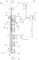
- the atmospheric pressure etching apparatus 1 ⁇ / b> A includes a carry-on roller conveyor 33, a process roller conveyor 34, and a carry-out roller conveyor as the transfer means 30 for the substrate 9 to be processed. 35.
- Each of the roller conveyors 33, 34, and 35 has a plurality of roller shafts 31 arranged in the x direction (left and right direction in FIG. 3), and a conveyance roller 32 provided on each roller shaft 31.
- the carrying-in roller conveyor 33 is disposed on one end side in the x direction (right side in FIG. 3) from the processing unit 20, and carries the substrate 9 to be processed into the processing space 23.
- the processing roller conveyor 34 is provided below the bottom plate 22 and conveys the substrate 9 to be processed in the processing space 23.
- the carry-out roller conveyor 35 is disposed on the other end side in the x direction (left in FIG. 3) from the processing unit 20, and carries the substrate 9 to be processed out of the processing space 23.
- a plurality of covers 70 for the processing roller conveyor 34 are provided at the bottom of the bottom plate 22.
- the cover 70 has a one-to-one correspondence with the roller shaft 31 of the processing roller conveyor 34.
- the cover 70 has a container shape extending long in the axial direction y of the roller shaft 31.
- Each cover 70 accommodates a corresponding roller shaft 31 and transport roller 32.
- the upper surface of the cover 70 is opened and abutted against the lower surface of the bottom plate 22.
- the cover 70 may be made of a metal such as aluminum or may be made of a resin such as vinyl chloride.
- a resin film having high fluorine resistance and plasma resistance, such as polytetrafluoroethylene, may be provided on the inner surface of the cover 70.
- the roller shaft 31 of the processing roller conveyor 34 passes through end walls 74 on both sides in the longitudinal direction of the cover 70.
- An airtight bearing 75 is provided on the end wall 74.
- the roller shaft 31 is rotatably supported by the airtight bearing 75.
- the space between the roller shaft 31 and the end wall 74 is hermetically sealed by the hermetic bearing 75.
- the constituent member of the hermetic bearing 75 is preferably made of a resin having high fluorine resistance and plasma resistance, such as polytetrafluoroethylene.
- the inside of the cover 70 communicates only with the processing space 23 through the roller hole 25.
- the second embodiment it is possible to prevent outside air (air or the like) below the atmospheric pressure etching apparatus 1A from being drawn into the processing space 23 through the roller hole 25. Further, when the processing gas in the processing space 23 leaks to the lower side of the bottom plate 22 through the roller hole 25, the processing gas can be confined inside the cover 70. Therefore, it is possible to prevent the processing gas from leaking to the outside.
- outside air air or the like
- the suction nozzle 50 of the second embodiment is disposed in the middle portion of the bottom plate 22 in the x direction.
- the top plate 21 and the bottom plate 22 extend from the suction nozzle 50 to the other end side in the x direction (left side in FIG. 3), that is, the downstream side in the transport direction of the substrate 9. Only a portion corresponding to the space between the blowing nozzle 40 and the suction nozzle 50 in the top plate 21 may be kept at the set temperature as the adjusting means, and the entire area of the top plate 21 is kept at the set temperature as the adjusting means. You may come to be.
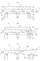
- the atmospheric pressure etching apparatus 1 ⁇ / b> B of this embodiment does not have the bottom plate 22.
- a processing space 23 is defined by the entire upper surface of the blowing nozzle 40 and the lower surface of the top plate 21.
- a processing atmosphere containing HF vapor and water vapor exists in the processing space 23.
- the atmospheric pressure etching apparatus 1 ⁇ / b> B includes a gas suction system 80.
- the gas suction system 80 includes a suction pump 81 and a pair of accessory plates 82 and 84.
- the pair of attachment plates 82 and 84 are arranged vertically on both sides in the x direction with the blowing nozzle 40 interposed therebetween.
- the upper ends of the attachment plates 82 and 84 are aligned with the upper surface of the blowing nozzle 40.
- the thickness of the attachment plates 82 and 84 is, for example, about several mm to several tens of mm, and is about 5 mm here.
- the loading plate 82 on the carry-in side extends in the y direction perpendicular to the x direction along the carry-out outer surface of the blowout nozzle 40.
- a suction path 83 is defined between the attachment plate 82 and the outer surface on the carry-in side of the blowing nozzle 40.
- a lower end portion of the suction path 83 is connected to the suction pump 81.
- the upper end portion (suction port) of the suction path 83 is continuous with the end portion on the carry-in side of the processing space 23.
- the opening width in the x direction of the suction port of the suction path 83 is, for example, about several mm to several tens mm, and here is about 10 mm.
- the carry-in entrance 26 is arranged in the vicinity of the suction port of the suction path 83.
- the carry-in entrance 26 is defined by an upper end portion of the attachment plate 82 and an end portion on the carry-in side of the top plate 21.
- the carry-in entrance 26 is continuous with the end portion on the carry-in side of the processing space 23 and is connected with the suction path 83.
- the carry-out side (left in the drawing) splicing plate 84 extends in the y direction along the outer surface of the blowout nozzle 40 on the carry-out side.
- a suction path 85 is defined between the attachment plate 84 and the outer surface of the outlet nozzle 40 on the carry-out side.
- a lower end portion of the suction path 85 is connected to the suction pump 81.
- the upper end portion (suction port) of the suction path 85 is connected to the end portion on the carry-out side of the processing space 23.
- the opening width in the x direction of the suction port of the suction path 85 is, for example, about several mm to several tens mm, and here is about 10 mm.
- the carry-out port 27 is arranged in the vicinity of the suction port of the suction path 85.
- the carry-out port 27 is defined by the upper end portion of the attachment plate 84 and the end portion on the carry-out side of the top plate 21.
- the carry-out port 27 is continuous with the end portion on the carry-out side of the processing space 23 and is connected with the suction path 85.
- end walls 86 are provided at both ends in the width direction y of the processing unit 20. Both end portions in the width direction y of the suction paths 83 and 85 are closed by the end walls 86.
- the plasma-ized processing gas g1 is blown into the processing space 23 from the blowing port 41.
- the suction pump 81 of the gas suction system 80 is driven to perform gas suction from the suction paths 83 and 85.
- the processing gas g1 is on the carry-in side (in the drawing, in the portion directly above the outlet 41 in the processing space 23). It is divided into a flow toward the right) and a flow toward the carry-out side (left in the figure).
- the processing gas directed toward the carry-in side is sucked into the suction path 83 from the end of the process space 23 on the carry-in side.
- the processing gas directed to the carry-out side is sucked into the suction path 85 from the end of the treatment space 23 on the carry-out side.
- the outside air enters the carry-in entrance 26 by the gas suction of the gas suction system 80. This outside air is sucked into the suction path 83 from the carry-in entrance 26. Similarly, outside air also enters the carry-out port 27. This outside air is sucked into the suction path 85 from the carry-out port 27. Therefore, the outside air hardly flows into the processing space 23 between the upper surface of the blowing nozzle 40 and the top plate 21. Therefore, the gas composition of the processing atmosphere in the processing space 23 is substantially equal to the composition of the processing gas itself after being converted to plasma. That is, the HF partial pressure and the water vapor partial pressure in the processing space 23 are substantially equal to the HF partial pressure and the water vapor partial pressure of the processing gas itself. Therefore, even if the humidity or temperature of the outside air fluctuates, the HF partial pressure and the water vapor partial pressure in the processing space 23 hardly fluctuate.
- the inflowing outside air g2 includes outside air g2a passing above the substrate 9 to be processed and outside air g2b passing below the second surface 9b. Among them, the lower inflowing outside air g ⁇ b> 2 b is sucked into the suction path 83 immediately from the carry-in entrance 26. Therefore, the lower inflowing outside air g2b hardly enters the processing space 23.
- the upper inflowing outside air g ⁇ b> 2 a wraps downward along the end surface of the substrate 9 to be processed and is sucked into the suction path 83 when the end of the substrate 9 to be processed is located at the carry-in entrance 26. Therefore, the upper inflowing outside air g2a hardly enters the processing space 23. Therefore, even if the flow rate and flow velocity of the inflowing outside air g2 fluctuate when the end portion of the substrate 9 to be processed is carried in from the carry-in entrance 26, it is possible to suppress or prevent the gas composition in the processing space 23 from fluctuating.
- the substrate to be processed 9 eventually covers the suction path 83.
- the suction force of the gas suction system 80 does not work much in the portion of the processing space 23 above the substrate 9 to be processed (hereinafter referred to as “first processing space portion 23a”), and the suction flow rate of the outside air g2a Decrease.
- the upper outside air g2a can flow into the carry-in entrance 26 due to its viscosity with the upper surface of the substrate 9 to be processed, but the amount of the inflow can be sucked by the suction system 80 (FIGS. 7A to 7B). Compared to small enough. Therefore, the processing atmosphere between the top plate 21 and the substrate 9 to be processed is maintained at the same gas composition as the processing gas itself.
- the inflow amount of the outside air g2b from the lower side of the substrate 9 to be processed increases as the inflow amount of the upper outside air g2a decreases. Even if the flow rate is increased, almost all of the inflowing outside air g2b is immediately sucked into the suction path 83. Therefore, the outside air g2b hardly enters the processing space 23, and the processing atmosphere in the processing space (hereinafter referred to as “second processing space portion 23b”) between the substrate 9 to be processed and the blowing nozzle 40 is the processing gas itself. Is maintained at about the same gas composition.
- the etching apparatus 1B even if the flow rate and flow rate of the outside air g2 flowing into the processing space 23 through the carry-in port 26 and the carry-out port 27 vary with the loading and unloading of the substrate 9 to be processed,
- the gas composition of the treatment atmosphere, and thus the HF partial pressure and the water vapor partial pressure can be maintained substantially the same as those of the treatment gas itself.
- the first surface 9a is etched. Even when the humidity of the outside air is considerably higher than the humidity of the processing gas and the processing atmosphere in the processing space 23, it is possible to reliably prevent the formation of a condensed layer on the first surface 9a, and the first surface 9a is etched. Can be surely avoided. As will be described later, in the state of FIG. 7C, even when outside air g2a is involved in the first processing space 23a, only the second surface 9b is roughened by controlling the amount of entrainment. Is possible.
- the present invention is not limited to the above embodiment, and various modifications can be made without departing from the spirit of the present invention.
- the first surface 9a is the main surface on which the electronic element is to be provided
- the second surface 9b to be roughened (etched) is the back surface.
- the first surface 9a is the back surface, and the rough surface is rough.
- the second surface 9a to be converted (etched) may be a main surface on which an electronic element is to be provided. Both the first surface and the second surface may be surfaces on which electronic elements are provided.
- the substrate to be processed is not limited to glass but may be a semiconductor wafer or the like. Further, the substrate to be processed is not limited to a substrate on which an electronic element is formed or a substrate for a semiconductor device.
- the silicon-containing material to be etched is not limited to SiO 2 but may be SiN, Si, SiC, SiOC, or the like.
- a film made of a silicon-containing material may be formed on the substrate 9 to be processed, and the apparatus 1 of the present invention may etch the film.
- the temperature adjusting means for the first surface 9a and the second surface 9b of the substrate 9 to be processed may be an electric heater, a heat medium heater, or a radiant heater other than the plate heater.
- the heat medium heater for example, the top plate 21 may have a heat medium flow path for passing a heat medium such as temperature-controlled water or a storage chamber for storing the heat medium.
- the temperature of the heating medium stored in the storage chamber may be adjusted by heating or the like.
- the temperature of the entire area of the top plate 21 may be adjusted, and the temperature of a part of the top plate 21 (for example, the central portion or one end portion) is partially adjusted. It may be.
- the temperature adjusting means (heater) may be provided separately from the top plate 21, and the temperature adjusting means (heater) heats the top plate 21, and the second substrate 9 is processed via the top plate 21.
- the first surface 9a may be heated.
- the second surface 9b of the substrate to be processed may be cooled so that the temperature of the second surface 9b is adjusted to a desired temperature lower than the condensation point.
- the second plate 9b of the substrate to be processed may be cooled by providing a medium flow path for passing a cooling medium such as cold water through the bottom plate 22 and cooling the bottom plate 22.
- the cooling means of the second surface 9b is an element of “adjustment means” in the claims. It is preferable to adjust the temperature of the second surface 9b by the cooling means so that it is 0 ° C. to 10 ° C. lower than the condensation point.
- the humidity around the apparatus 1 may be adjusted, and consequently the water vapor partial pressure in the processing atmosphere may be adjusted.
- the humidity adjusting means around the device 1 is an element of “adjusting means” in the claims.
- the processing gas may contain a certain amount of moisture.
- the partial pressure of water vapor in the processing atmosphere may greatly depend on the amount of water added by the water addition unit 12.
- the water addition part 12 becomes an element of the “adjustment means” in the claims.
- the plasma generation unit 60 may be provided outside the blowing nozzle 40 or may be provided apart from the blowing nozzle 40.
- the processing gas may be transported to the blowing nozzle 40 after the raw material gas is turned into plasma by the plasma generation unit 60 to generate the processing gas.
- the processing gas is not limited to one formed by plasma.
- a tank storing a hydrogen fluoride aqueous solution may be prepared as a processing gas source, and the hydrogen fluoride aqueous solution may be vaporized and transported to the blowing nozzle 40.
- the processing gas may contain an oxidizing component such as ozone. Ozone can be generated with an ozonizer or oxygen plasma generator.
- the posture of the substrate 9 to be processed is not limited to horizontal, but may be vertical, or may be horizontal or oblique to the vertical.
- the second surface of the substrate 9 to be processed may be directed upward and the first surface may be directed downward.
- the temperature adjusting means (heater) is disposed on the lower side of the substrate 9 to be processed, the blowing nozzle 40 is disposed on the upper side of the substrate 9 to be processed, and the processing gas is sprayed from above the substrate 9 to be processed. It may be.
- the substrate 9 to be processed is not limited to moving in one direction in the direction of the arrow a in the x direction, but may be reciprocated in the processing space 23.
- Support means for supporting the substrate 9 to be processed may be provided separately from the transport means 30.
- the position of the substrate 9 to be processed may be fixed by the support means, and the processing unit 20 may be moved by the transport means.
- the etching process is not limited to the process of moving the substrate 9 and the processing unit 20 relative to each other, and the etching process may be performed with the relative positions of the substrate 9 and the process unit 20 fixed.
- Example 1 the atmospheric pressure etching apparatus 1 substantially the same as in FIGS. 1 and 2 was used.
- a glass substrate was used as the substrate 9 to be processed, and SiN (silicon-containing material) was coated on the first surface 9a and the second surface 9b.
- the dimensions of the substrate 9 to be processed were as follows. Length along the x direction: 670 mm Width in y direction: 550mm Thickness: 0.7mm
- the composition of the source gas was as follows. Ar: 8.7 slm CF 4 : 0.3 slm H 2 O: 0.19 sccm
- the raw material gas was turned into plasma by the rectifying unit 42 to generate a processing gas. Therefore, the flow rate of the processing gas was a little over 9 sccm.
- the exhaust amount from the suction port 51 was 500 slm. Thereby, the outside air drawn into the processing space 23 from the carry-in port 26 was about 120 slm.
- the partial pressure of hydrogen fluoride in the processing atmosphere and the processing atmosphere in the processing space 23 was 6.2 Torr.
- the area around the apparatus was atmospheric pressure, the temperature around the apparatus (room temperature) was 25 ° C., and the relative humidity was about 30%. As shown in FIG. 11, the water vapor partial pressure corresponding to this relative humidity is 7.1 Torr.
- the condensation point of hydrogen fluoride and water in the treatment atmosphere is about 27 ° C.
- the initial temperature before carrying the substrate 9 into the processing space 23 was 25 ° C.
- the substrate 9 to be processed was conveyed in the direction of the arrow a in the x direction and passed through the processing space 23.
- the number of times the substrate 9 was passed through the processing space 23 was one.
- the conveyance speed of the substrate 9 to be processed was 4 m / min.
- the blowing of the processing gas from the blow-out nozzle 40 started before the substrate 9 to be processed was carried into the processing space 23 and continued until the substrate 9 to be processed was carried out of the processing space 23.
- the top plate that is, the plate heater 21 was kept at the set temperature, and the temperature of the first surface 9a was adjusted.
- the heater 21 has four set temperatures, 25 ° C., 30 ° C., 35 ° C., and 45 ° C. At 25 ° C., condensation was formed on the lower surface of the top plate 21. At 30 ° C., 35 ° C., and 45 ° C., no condensation was formed on the lower surface of the top plate 21. When the top plate 21 was heated from 25 ° C., condensation disappeared at 27 ° C. to 28 ° C.
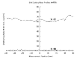
- the etching rates of the SiN film on the first surface 9a and the SiN film on the second surface 9b were measured.
- the measurement position was set at intervals of 1 mm in the width direction y at the center in the x direction of the surfaces 9a and 9b of the substrate 9 to be processed.
- the etching depth (nm / scan) per scan (one-way transport) was determined by dividing the etching depth by the number of scans. Furthermore, the average value of the etching rate at each measurement position on each of the surfaces 9a and 9b was obtained.
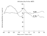
- FIG. 8 shows the average etching rate.
- the heater set temperature was 25 ° C.
- the SiN film on the second surface 9b not only the SiN film on the second surface 9b but also the SiN film on the first surface 9a were etched to the same extent as the second surface 9b side.
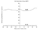
- the heater set temperature was 30 ° C.
- a sufficient etching amount was obtained for the SiN film on the second surface 9b, whereas the etching amount of the SiN film on the first surface 9a was extremely small, and the SiN film was almost completely removed. It was confirmed that it was not etched.
- the heater set temperatures were 35 ° C.
- FIGS. 9 and 10 show the etching rates at the respective measurement positions on the surfaces 9a and 9b, and show the distribution of the etching rate in the width direction y.
- the etching rate varies greatly depending on the position in the width direction y on both the first surface 9a and the second surface 9b.
- the arrangement position of the conveying roller 33 was -35 mm, 0 mm, and 35 mm on the horizontal axis in FIGS. 9 and 10.
- the condensation conditions corresponding to the temperature of the HF—H 2 O system were calculated and plotted.
- a horizontal broken line indicates relative humidity (% RH) and corresponds to the H 2 O partial pressure of the processing atmosphere.
- the point A corresponding to the H 2 O partial pressure (7.1 Torr (relative humidity 30%)) and the HF partial pressure (6.2 Torr) of the processing atmosphere of Example 1 is a gas-liquid equilibrium curve at 25 ° C. Is located on the gas phase side, and is located on the liquid phase side for a vapor-liquid equilibrium curve of 30 ° C. or higher.
- Example 1 agreed with theoretical calculation data. Accordingly, when setting the processing conditions, the graph illustrated in FIG. 11 is used, and the points on the graph corresponding to the HF partial pressure and the H 2 O partial pressure of the processing atmosphere are room temperature or the initial temperature of the substrate 9 to be processed.
- the heater set temperature and the process gas recipe (of the raw material gas component) are positioned so that they are located on the gas phase side of the gas-liquid equilibrium curve corresponding to the gas temperature and on the liquid phase side of the gas-liquid equilibrium curve corresponding to the heater set temperature.
- the flow rate, the added amount of water vapor, etc. may be set.
- FIG. 12 is a graph of HF—H 2 O-based condensation conditions in the etching apparatus 1B of the third embodiment (FIGS. 5 to 7).
- the gas composition of the processing atmosphere is almost the same as the gas composition of the processing gas after being converted to plasma.
- the H 2 O partial pressure of the humidified fluorine-based raw material gas, that is, the processing gas (CF 4 + Ar + H 2 O) before the plasma treatment is, for example, 10.8 Torr (the one-dot chain line L1 in FIG. 12).
- the water in the process gas is decomposed by plasma.
- the H 2 O partial pressure of the processing gas after the plasma formation is lower than that before the plasma formation, for example, 8.1 Torr (broken line L2 in FIG. 12).
- the HF partial pressure of the processing gas after being converted to plasma is, for example, 4.2 Torr (broken line L3 in FIG. 12).
- An intersection B between the broken line L2 and the broken line L3 indicates the HF and H 2 O partial pressures of the processing gas after being converted to plasma, and by extension, the HF and H 2 O partial pressures of the processing atmosphere in the processing space 23. Therefore, if the temperature of the second surface 9b of the substrate 9 to be processed is, for example, about 25 ° C.
- a condensed layer of hydrofluoric acid is formed on the second surface 9b.
- the surface 9b can be etched reliably. And if the temperature of the 1st surface 9a of the to-be-processed substrate 9 is heated with the heater 21 so that it may become about 30 degreeC higher than the point B, it can avoid forming a condensed layer in the 1st surface 9a, It is possible to reliably prevent the first surface 9a from being etched.
- the first surface 9a of the substrate 9 to be processed is not higher than the point B by the heater 21, the first surface 9a can be prevented from being etched.
- the case where the gas composition of the processing atmosphere indicated by the point B in FIG. 12 and the temperature of the processing atmosphere is 25 ° C. will be described as an example.
- the distance between the lower surface of the heater 21 and the first surface 9a of the substrate 9 to be processed is increased.
- the atmosphere of the processing space 23 is a condition indicated by a point B, the processing target 9 enters the processing space 23 from the carry-in entrance 26, so that outside air is involved.
- outside air enters the second processing space portion 23b between the second surface 9b and the upper surface of the blowing nozzle 40 due to the processing gas blowing out and exhausting from the suction path 83 on the carry-in side in front of the processing space. It does n’t come.
- outside air enters the first processing space 23 a between the first surface 9 a and the heater 21. Then, the HF partial pressure in the first processing space portion 23a decreases, and the partial pressure composition of the processing atmosphere changes from the point B to the gas phase side across the 25 ° C. gas-liquid equilibrium curve. Therefore, no condensed layer is formed on the first surface 9a, and the first surface 9a is not etched.
- the outside air is preferably less humid than the processing gas.
- the present invention can be applied to the manufacture of semiconductor devices such as flat panel displays.
Landscapes
- Engineering & Computer Science (AREA)
- Physics & Mathematics (AREA)
- Plasma & Fusion (AREA)
- Power Engineering (AREA)
- Chemical & Material Sciences (AREA)
- Condensed Matter Physics & Semiconductors (AREA)
- General Physics & Mathematics (AREA)
- Manufacturing & Machinery (AREA)
- Computer Hardware Design (AREA)
- Microelectronics & Electronic Packaging (AREA)
- Analytical Chemistry (AREA)
- Life Sciences & Earth Sciences (AREA)
- Chemical Kinetics & Catalysis (AREA)
- General Chemical & Material Sciences (AREA)
- Geochemistry & Mineralogy (AREA)
- Materials Engineering (AREA)
- Organic Chemistry (AREA)
- Spectroscopy & Molecular Physics (AREA)
- Drying Of Semiconductors (AREA)
Abstract
Description
CF4+2H2O→4HF+CO2 (式1)
SiO2+4HF+H2O→SiF4+3H2O (式2)
フッ化水素蒸気及び水蒸気を含有する処理雰囲気中に前記被処理基板を配置し、
前記第1面の温度を前記処理雰囲気のフッ化水素及び水の凝縮点より高温になるよう、かつ前記第2面の温度を前記凝縮点以下になるよう調節することを特徴とする。
第1面の加温度ひいては第1面に付与すべき熱量を小さくすることにより、熱が第2面まで伝達するのを回避又は抑制でき、第2面の温度上昇を防止又は抑制できる。したがって、第2面の温度を確実に前記凝縮点以下にすることができる。よって、第1面のエッチングを確実に防止又は抑制しながら、第2面を確実にエッチングすることができる。
凝縮点と第2面の温度との差を小さくすることにより、第1面を少し加温すれば、第1面の温度が前記凝縮点を上回るようにすることができる。第1面の加温度ひいては第1面に付与すべき熱量を小さくすることにより、熱が第2面まで伝達するのを回避又は抑制でき、第2面の温度上昇を防止又は抑制できる。したがって、上記第2面の温度を確実に前記凝縮点以下にすることができる。よって、第1面のエッチングを確実に防止又は抑制しながら、第2面を確実にエッチングすることができる。
これによって、外気が搬入口又は搬出口を通って処理空間に達する前に、搬入口又は搬出口の近傍で吸引して排気でき、外気が処理空間に流入するのを防止できる。上記の流入外気の流量や流速は、被処理基板の搬入及び搬出に伴って変動する。このような変動があっても、上記の吸引によって処理雰囲気への外気混入を防止できるから、処理雰囲気のガス組成ひいてはフッ化水素蒸気分圧及び水蒸気分圧を、それぞれ処理ガス自体のものと略同じに維持することができる。この結果、第2面のエッチング処理が不均一になるのを防止することができる。また、処理雰囲気の湿度に対して外気の湿度が高くても第1面側の処理雰囲気の湿度が上昇するのを防止でき、第1面に凝縮層が形成されるのを防止できる。したがって、第1面までもがエッチングされてしまうのを回避できる。
フッ化水素及び水のうち少なくともフッ化水素を含有する処理ガスを前記処理空間内に供給して前記被処理基板の少なくとも前記第2面に接触させる吹出ノズルと、
前記第1面の温度が前記処理空間におけるフッ化水素及び水の凝縮点より高温になるよう、かつ前記第2面の温度が前記凝縮点以下になるよう調節する調節手段と、
を備えたことを特徴とする。
前記処理空間の湿度は、0%を超えていればよく、100%RH以下であればよい。
前記調節手段が、前記処理空間における前記被処理基板が配置される位置を挟んで前記吹出ノズルとは反対側において前記位置に近接して配置されたヒータを含み、前記ヒータの設定温度が前記凝縮点より0℃超~60℃高温であることが好ましい。
これにより、被処理基板の第1面の温度を処理雰囲気のフッ化水素及び水の凝縮点より確実に高温にすることができる。第1面の加温度ひいては第1面に付与すべき熱量を小さくすることにより、熱が第2面まで伝達するのを回避又は抑制でき、第2面の温度上昇を防止又は抑制できる。したがって、上記第2面の温度を確実に前記凝縮点以下にすることができる。これにより、第1面のエッチングを確実に抑制又は防止しながら、第2面を確実にエッチングすることができる。
例えば、前記移動速度が比較的大きいときは、前記設定温度を前記第1面の所望温度より比較的大きくする。これによって、前記第1面が前記所望温度に達する迄の所要時間を短縮できる。一方、移動速度が比較的大きいから、第2面までもが前記凝縮点より高温にならないうちに処理を終了できる。
前記移動速度が比較的小さいときは、前記設定温度を前記所望温度とほぼ同じにしてもよい。これによって、被処理基板の温度が前記所望温度を大きく超えるのを回避できる。一方、移動速度が小さいと加熱時間が長くなるが、前記設定温度及び前記所望温度を前記凝縮点より少しだけ高温に設定することによって、第2面の温度を前記凝縮点以下に維持することができる。
処理雰囲気のフッ化水素及び水の凝縮点と第2面の温度との差を小さくすることにより、第1面を少し加温すれば、第1面の温度が前記凝縮点を上回るようにすることができる。第1面の加温度ひいては第1面に付与すべき熱量を小さくすることにより、熱が第2面まで伝達するのを回避又は抑制でき、第2面の温度上昇を防止又は抑制できる。したがって、上記第2面の温度を確実に前記凝縮点以下にすることができる。よって、第1面のエッチングを確実に抑制又は防止しながら、第2面を確実にエッチングすることができる。
図1及び図2は、本発明の第1実施形態を示したものである。被処理基板9は、例えばフラットパネルディスプレイ等の半導体装置になるべきガラス基板である。ガラス基板9は、SiO2等のシリコン含有物を主成分として含んでいる。ガラス基板9の厚さは、例えば0.5mm~0.7mm程度である。ガラス基板9は、四角形の平板状をなし、おもて側の第1面9a(主面)と、その裏側の第2面9b(裏面)とを有している。第1面9aは、絶縁層、導電層、半導体層等の各種電子素子層が設けられるべき主面である。第2面9bは、大気圧エッチング装置1による粗化(エッチング)処理の対象となる裏面である。第2面9bを粗化処理したうえで、第1面9aに対し、上記各種電子素子層を形成するための表面処理を行なう。
水添加後の原料ガス中の水分量は、水添加前の原料ガスの露点と、水添加部12における水の気化量とから算出することができる。フーリエ変換型赤外分光器(FTIR)を用いて水添加後の原料ガス中の水分量を測定してもよい。
COF2+H2O→2HF+CO2 (式3)
フッ素系原料供給部11からの原料ガス(CF4+Ar)に水添加部12にて所定量の水蒸気(H2O)を添加し、加湿原料ガスを得る。この加湿原料ガス(CF4+Ar+H2O)を整流部42にて幅方向yに均一化したうえで、プラズマ生成部60にてプラズマ化する。これにより、フッ化水素及び水のうち少なくともフッ化水素を含む処理ガスを生成する。水添加部12における水蒸気添加量等を調節することによって、処理ガスのフッ化水素分圧及び水蒸気分圧を調節できる。ここでは、原料ガス中の水分の殆ど全量がフッ化水素の生成に消費され、処理ガスの水蒸気分圧は実質0である。処理ガスの温度は室温付近である。
図3及び図4に示すように、第2実施形態の大気圧エッチング装置1Aは、被処理基板9の搬送手段30として、搬入用ローラコンベア33と、処理用ローラコンベア34と、搬出用ローラコンベア35を備えている。各ローラコンベア33,34,35が、x方向(図3の左右方向)に並べられた複数のローラシャフト31と、各ローラシャフト31に設けられた搬送ローラ32を有している。搬入用ローラコンベア33は、処理部20よりx方向の一端側(図3において右)に配置され、被処理基板9を処理空間23に搬入する。処理用ローラコンベア34は、底板22の下部に設けられ、処理空間23内の被処理基板9を搬送する。搬出用ローラコンベア35は、処理部20よりx方向の他端側(図3において左)に配置され、被処理基板9を処理空間23から搬出する。
カバー70の内部は、ローラ穴25を介して処理空間23とのみ連通している。
なお、後述するように、図7(c)の状態において、第1処理空間部23aへの外気g2aの巻き込みが有る場合でも、この巻き込み量等を制御することで第2面9bのみを粗化可能である。
例えば、上記実施形態では、第1面9aが電子素子を設けるべき主面であり、粗化(エッチング)すべき第2面9bが裏面であったが、第1面9aが裏面であり、粗化(エッチング)すべき第2面9aが電子素子を設けるべき主面であってもよい。第1面と第2面の両方が、電子素子が設けられる面であってもよい。被処理基板は、ガラスに限られず、半導体ウェハ等でもよい。更に、被処理基板は、電子素子が形成される基板ないしは半導体装置用の基板に限られない。
被処理基板9にシリコン含有物からなる膜が形成されていてもよく、本発明装置1が上記膜をエッチングするものであってもよい。
装置1の周辺の湿度を調節し、ひいては処理雰囲気中の水蒸気分圧を調節することにしてもよい。この場合、装置1の周辺の湿度調節手段は、特許請求の範囲の「調節手段」の要素になる。
処理ガスがある程度の水分を含有するようにしてもよい。処理雰囲気中の水蒸気分圧が、水添加部12による水添加量に大きく依存するようにしてもよい。この場合、水添加部12は、特許請求の範囲の「調節手段」の要素になる。
処理ガスは、プラズマ化により形成するものに限られない。例えば、処理ガス源としてフッ化水素水溶液を蓄えたタンクを用意し、上記フッ化水素水溶液を気化させて吹出ノズル40へ輸送することにしてもよい。
処理ガスが、オゾン等の酸化成分を含んでいてもよい。オゾンはオゾナイザーや酸素プラズマ生成装置にて生成できる。
被処理基板9の第2面を上に向け、第1面を下に向けてもよい。温度調節手段(ヒータ)を被処理基板9の下側に配置し、吹出ノズル40を被処理基板9の上側に配置して、処理ガスを被処理基板9の上方から被処理基板9に吹き付けることにしてもよい。
被処理基板9を支持する支持手段を搬送手段30とは別途に設けてもよい。支持手段にて被処理基板9の位置を固定し、搬送手段にて処理部20を移動させることにしてもよい。被処理基板9及び処理部20を互いに相対移動させながらエッチング処理を行なうのに限られず、被処理基板9及び処理部20の相対位置を固定した状態でエッチング処理を行なうことにしてもよい。
実施例1では、図1及び図2と実質的に同じ大気圧エッチング装置1を用いた。
被処理基板9としてガラス基板を用い、第1面9a及び第2面9bにそれぞれSiN(シリコン含有物)を被膜した。
被処理基板9の寸法は、以下の通りであった。
x方向に沿う長さ:670mm
y方向の幅:550mm
厚さ:0.7mm
底板22のx方向に沿う長さ: 0.3m
処理空間23の上下方向の厚さ: d0=8mm
処理空間23のy方向の幅: 600mm
ワーキングディスタンス: WD=4mm
天板すなわちプレートヒータ21の下面と被処理基板9の上面との距離: d1=4mm
Ar: 8.7slm
CF4: 0.3slm
H2O: 0.19sccm
上記原料ガスを整流部42にてプラズマ化して処理ガスを生成した。したがって、処理ガスの流量は、9sccm強であった。
プラズマ生成条件は以下の通りとした。
電極間間隔: 1mm
電極間電圧: Vpp=12.8kV
電極間電圧の周波数: 25kHz(パルス波)
供給電力: パルス変換前の直流電圧=370V、電流=9.4A
処理ガスひいては処理空間23内の処理雰囲気のフッ化水素分圧は6.2Torrであった。
装置周辺は大気圧であり、装置周辺の温度(室温)は、25℃であり、相対湿度は、約30%であった。図11に示すように、この相対湿度に対応する水蒸気分圧は、7.1Torrである。また、この処理雰囲気中のフッ化水素及び水の凝縮点は約27℃である。
被処理基板9をx方向の矢印aの向きに搬送して処理空間23に通した。被処理基板9を処理空間23に通した回数(スキャン回数)は、1回であった。
被処理基板9の搬送速度は、4m/minとした。
吹出ノズル40からの処理ガスの吹き出しは、被処理基板9を処理空間23に搬入する前から開始し、被処理基板9が処理空間23から搬出されるまで継続して行った。
25℃では天板21の下面に結露が形成された。30℃、35℃、45℃では、天板21の下面に結露が形成されなかった。なお、天板21を25℃から加温していくと、27℃~28℃で結露が消失した。
ヒータ設定温度が30℃のときは、第2面9bのSiN膜については十分なエッチング量を得られたのに対し、第1面9aのSiN膜のエッチング量が極めて小さくなり、SiN膜が殆どエッチングされないことが確認された。
ヒータ設定温度が35℃及び45℃のときについても、30℃のときと同様に、第2面9bのSiN膜については十分なエッチング量を得られたのに対し、第1面9aのSiN膜は殆どエッチングされなかった。
以上の結果から、第1面9aの温度を処理雰囲気中のフッ化水素及び水の凝縮点より高温にし、かつ第2面9bの温度を上記凝縮点より低温にすることにより、第1面9aがエッチングされるのを抑制又は防止しながら、第2面9bをエッチングできることが確認された。
図10(a)及び図10(b)に示すように、ヒータ設定温度が35℃及び45℃のときについても、30℃のときと同様に、第1面9a、第2面9b共に、エッチングレートがほぼ均一になった。
以上の結果から、第1面9aを処理雰囲気中のフッ化水素及び水の凝縮点より高温にすることで、第1面9aのエッチングが抑制されるだけでなく、第1面9a及び第2面9bのエッチングの均一性が高まることが判明した。
図5に示す第3実施形態において、ヒータ21の下面と被処理基板9の第1面9aとの距離を広げる。処理空間23の雰囲気は点Bで示される条件であるが、被処理基板9が搬入口26から処理空間23に入ることで、外気を巻き込んでくる。ところが、吹き出てくる処理ガスおよび搬入側の吸引路83からの処理空間手前での排気によって、第2面9bと吹出ノズル40の上面との間の第2処理空間部23bには、外気が入ってこない。一方、第1面9aとヒータ21との間の第1処理空間部23aには、外気が入ってくる。すると、第1処理空間部23aのHF分圧が下がり、点Bから25℃の気液平衡曲線を跨いだ気相側に処理雰囲気の分圧組成が変わる。したがって、第1面9aに凝縮層は形成されず、第1面9aはエッチングされない。
9 被処理基板
9a 第1面
9b 第2面
10 原料ガス供給手段
11 フッ素系原料供給部
12 水添加部
20 処理部
21 天板、プレートヒータ(調節手段)
22 底板
23 処理空間
24 側壁
25 ローラ穴
26 搬入口
27 搬出口
29 処理部内空間
30 搬送手段
31 ローラシャフト
32 搬送ローラ
33 搬入用ローラコンベア
34 処理用ローラコンベア
35 搬出用ローラコンベア
40 吹出ノズル
41 吹出し口
42 整流部
50 吸引ノズル
51 吸い込み口
60 プラズマ生成部
61 電極
62 放電空間
70 カバー
74 端壁
75 気密軸受
80 ガス吸引系
81 吸引ポンプ
82 搬入側の添え板
83 搬入側の吸引路
84 搬出側の添え板
85 搬出側の吸引路
86 端壁
Claims (7)
- シリコン含有物を含み、かつ第1面と該第1面の裏側の第2面とを有する被処理基板を大気圧近傍下にてエッチングする方法であって、
フッ化水素蒸気及び水蒸気を含有する処理雰囲気中に前記被処理基板を配置し、
前記第1面の温度を前記処理雰囲気のフッ化水素及び水の凝縮点より高温になるよう、かつ前記第2面の温度を前記凝縮点以下になるよう調節することを特徴とするエッチング方法。 - 前記第1面の温度を前記凝縮点より0℃超~40℃高温にすることを特徴とする請求項1に記載のエッチング方法。
- 前記第2面の温度を前記凝縮点より0℃~10℃低温にすることを特徴とする請求項1又は2に記載のエッチング方法。
- 前記処理雰囲気が存する処理空間に連なる搬入口から前記被処理基板を前記処理空間に搬入し、前記処理空間に連なる搬出口から前記被処理基板を搬出し、前記搬入口の近傍及び前記搬出口の近傍でガスを吸引することを特徴とする請求項1~3の何れか1項に記載のエッチング方法。
- シリコン含有物を含み、かつ第1面と該第1面の裏側の第2面とを有する被処理基板を大気圧近傍かつ湿度0%超の処理空間内にてエッチングする装置であって、
フッ化水素及び水のうち少なくともフッ化水素を含有する処理ガスを前記処理空間内に供給して前記被処理基板の少なくとも前記第2面に接触させる吹出ノズルと、
前記第1面の温度が前記処理空間におけるフッ化水素及び水の凝縮点より高温になるよう、かつ前記第2面の温度が前記凝縮点以下になるよう調節する調節手段と、
を備えたことを特徴とするエッチング装置。 - 前記調節手段が、前記処理空間における前記被処理基板が配置される位置を挟んで前記吹出ノズルとは反対側において前記位置に近接して配置されたヒータを含み、前記ヒータの設定温度が前記凝縮点より0℃超~60℃高温であることを特徴とする請求項5に記載のエッチング装置。
- 前記調節手段が、前記第2面の温度を前記凝縮点より0℃~10℃低温にすることを特徴とする請求項5又は6に記載のエッチング装置。
Priority Applications (3)
| Application Number | Priority Date | Filing Date | Title |
|---|---|---|---|
| CN2011800107060A CN102770944B (zh) | 2010-02-25 | 2011-02-21 | 蚀刻方法及装置 |
| KR1020127024873A KR101276482B1 (ko) | 2010-02-25 | 2011-02-21 | 에칭 방법 및 장치 |
| JP2012501768A JP5167430B2 (ja) | 2010-02-25 | 2011-02-21 | エッチング方法及び装置 |
Applications Claiming Priority (4)
| Application Number | Priority Date | Filing Date | Title |
|---|---|---|---|
| JP2010040768 | 2010-02-25 | ||
| JP2010-040768 | 2010-02-25 | ||
| JP2010214117 | 2010-09-24 | ||
| JP2010-214117 | 2010-09-24 |
Publications (1)
| Publication Number | Publication Date |
|---|---|
| WO2011105331A1 true WO2011105331A1 (ja) | 2011-09-01 |
Family
ID=44506739
Family Applications (1)
| Application Number | Title | Priority Date | Filing Date |
|---|---|---|---|
| PCT/JP2011/053704 WO2011105331A1 (ja) | 2010-02-25 | 2011-02-21 | エッチング方法及び装置 |
Country Status (5)
| Country | Link |
|---|---|
| JP (1) | JP5167430B2 (ja) |
| KR (1) | KR101276482B1 (ja) |
| CN (1) | CN102770944B (ja) |
| TW (1) | TWI415185B (ja) |
| WO (1) | WO2011105331A1 (ja) |
Cited By (11)
| Publication number | Priority date | Publication date | Assignee | Title |
|---|---|---|---|---|
| JP2013077721A (ja) * | 2011-09-30 | 2013-04-25 | Sekisui Chem Co Ltd | 表面粗化方法及び表面粗化装置 |
| CN103208443A (zh) * | 2012-01-11 | 2013-07-17 | 大日本网屏制造株式会社 | 基板处理方法以及基板处理装置 |
| JP2014047086A (ja) * | 2012-08-29 | 2014-03-17 | Avanstrate Inc | ガラス基板の製造方法 |
| WO2015159927A1 (ja) * | 2014-04-16 | 2015-10-22 | 旭硝子株式会社 | エッチング装置、エッチング方法、基板の製造方法、および基板 |
| WO2017043306A1 (ja) * | 2015-09-11 | 2017-03-16 | 日本電気硝子株式会社 | ガラス板の製造方法及びその製造装置 |
| JP2017052678A (ja) * | 2015-09-11 | 2017-03-16 | 日本電気硝子株式会社 | ガラス板の製造方法及びその製造装置 |
| WO2017043307A1 (ja) * | 2015-09-11 | 2017-03-16 | 日本電気硝子株式会社 | ガラス板の製造方法及びその製造装置 |
| KR20180051440A (ko) | 2015-09-11 | 2018-05-16 | 니폰 덴키 가라스 가부시키가이샤 | 유리 기판의 제조 방법 |
| KR20180053274A (ko) | 2015-09-11 | 2018-05-21 | 니폰 덴키 가라스 가부시키가이샤 | 유리 기판의 제조 방법 및 유리 기판의 제조 장치 |
| JP2019064896A (ja) * | 2017-10-05 | 2019-04-25 | 積水化学工業株式会社 | 表面処理装置 |
| JP2019071407A (ja) * | 2017-10-10 | 2019-05-09 | 積水化学工業株式会社 | 表面処理方法及び装置 |
Families Citing this family (2)
| Publication number | Priority date | Publication date | Assignee | Title |
|---|---|---|---|---|
| JP6854611B2 (ja) * | 2016-01-13 | 2021-04-07 | 東京エレクトロン株式会社 | 基板処理方法、基板処理装置及び基板処理システム |
| WO2018092556A1 (ja) * | 2016-11-16 | 2018-05-24 | 日本電気硝子株式会社 | ガラス基板の製造方法 |
Citations (4)
| Publication number | Priority date | Publication date | Assignee | Title |
|---|---|---|---|---|
| JP2001129798A (ja) * | 1999-08-28 | 2001-05-15 | Robert Bosch Gmbh | 表面マイクロマシニング型構造体の製法 |
| JP2007294642A (ja) * | 2006-04-25 | 2007-11-08 | Sekisui Chem Co Ltd | シリコンのエッチング方法 |
| JP2008288556A (ja) * | 2007-04-18 | 2008-11-27 | Shin Etsu Chem Co Ltd | 貼り合わせ基板の製造方法 |
| JP2008306175A (ja) * | 2007-05-09 | 2008-12-18 | Elpida Memory Inc | 基板の製造方法 |
Family Cites Families (3)
| Publication number | Priority date | Publication date | Assignee | Title |
|---|---|---|---|---|
| JP4167544B2 (ja) * | 2003-05-30 | 2008-10-15 | 積水化学工業株式会社 | プラズマエッチング方法及び装置 |
| JP5416590B2 (ja) * | 2007-10-05 | 2014-02-12 | 積水化学工業株式会社 | シリコンのエッチング方法 |
| JP4540729B2 (ja) * | 2008-03-13 | 2010-09-08 | 積水化学工業株式会社 | シリコン含有膜のエッチング方法および装置 |
-
2011
- 2011-02-21 KR KR1020127024873A patent/KR101276482B1/ko active IP Right Grant
- 2011-02-21 JP JP2012501768A patent/JP5167430B2/ja active Active
- 2011-02-21 WO PCT/JP2011/053704 patent/WO2011105331A1/ja active Application Filing
- 2011-02-21 CN CN2011800107060A patent/CN102770944B/zh active Active
- 2011-02-24 TW TW100106269A patent/TWI415185B/zh active
Patent Citations (4)
| Publication number | Priority date | Publication date | Assignee | Title |
|---|---|---|---|---|
| JP2001129798A (ja) * | 1999-08-28 | 2001-05-15 | Robert Bosch Gmbh | 表面マイクロマシニング型構造体の製法 |
| JP2007294642A (ja) * | 2006-04-25 | 2007-11-08 | Sekisui Chem Co Ltd | シリコンのエッチング方法 |
| JP2008288556A (ja) * | 2007-04-18 | 2008-11-27 | Shin Etsu Chem Co Ltd | 貼り合わせ基板の製造方法 |
| JP2008306175A (ja) * | 2007-05-09 | 2008-12-18 | Elpida Memory Inc | 基板の製造方法 |
Cited By (17)
| Publication number | Priority date | Publication date | Assignee | Title |
|---|---|---|---|---|
| JP2013077721A (ja) * | 2011-09-30 | 2013-04-25 | Sekisui Chem Co Ltd | 表面粗化方法及び表面粗化装置 |
| CN103208443A (zh) * | 2012-01-11 | 2013-07-17 | 大日本网屏制造株式会社 | 基板处理方法以及基板处理装置 |
| JP2014047086A (ja) * | 2012-08-29 | 2014-03-17 | Avanstrate Inc | ガラス基板の製造方法 |
| WO2015159927A1 (ja) * | 2014-04-16 | 2015-10-22 | 旭硝子株式会社 | エッチング装置、エッチング方法、基板の製造方法、および基板 |
| JP2017052680A (ja) * | 2015-09-11 | 2017-03-16 | 日本電気硝子株式会社 | ガラス板の製造方法及びその製造装置 |
| JP2017052678A (ja) * | 2015-09-11 | 2017-03-16 | 日本電気硝子株式会社 | ガラス板の製造方法及びその製造装置 |
| WO2017043307A1 (ja) * | 2015-09-11 | 2017-03-16 | 日本電気硝子株式会社 | ガラス板の製造方法及びその製造装置 |
| WO2017043305A1 (ja) * | 2015-09-11 | 2017-03-16 | 日本電気硝子株式会社 | ガラス板の製造方法及びその製造装置 |
| WO2017043306A1 (ja) * | 2015-09-11 | 2017-03-16 | 日本電気硝子株式会社 | ガラス板の製造方法及びその製造装置 |
| CN107709260A (zh) * | 2015-09-11 | 2018-02-16 | 日本电气硝子株式会社 | 玻璃板的制造方法及其制造装置 |
| KR20180050251A (ko) | 2015-09-11 | 2018-05-14 | 니폰 덴키 가라스 가부시키가이샤 | 유리판의 제조 방법 및 그 제조 장치 |
| KR20180051440A (ko) | 2015-09-11 | 2018-05-16 | 니폰 덴키 가라스 가부시키가이샤 | 유리 기판의 제조 방법 |
| KR20180053271A (ko) | 2015-09-11 | 2018-05-21 | 니폰 덴키 가라스 가부시키가이샤 | 유리판의 제조 방법 및 그 제조 장치 |
| KR20180053274A (ko) | 2015-09-11 | 2018-05-21 | 니폰 덴키 가라스 가부시키가이샤 | 유리 기판의 제조 방법 및 유리 기판의 제조 장치 |
| KR102505553B1 (ko) | 2015-09-11 | 2023-03-03 | 니폰 덴키 가라스 가부시키가이샤 | 유리 기판의 제조 방법 |
| JP2019064896A (ja) * | 2017-10-05 | 2019-04-25 | 積水化学工業株式会社 | 表面処理装置 |
| JP2019071407A (ja) * | 2017-10-10 | 2019-05-09 | 積水化学工業株式会社 | 表面処理方法及び装置 |
Also Published As
| Publication number | Publication date |
|---|---|
| CN102770944B (zh) | 2013-11-06 |
| KR101276482B1 (ko) | 2013-06-18 |
| JPWO2011105331A1 (ja) | 2013-06-20 |
| CN102770944A (zh) | 2012-11-07 |
| TW201145381A (en) | 2011-12-16 |
| JP5167430B2 (ja) | 2013-03-21 |
| KR20120114410A (ko) | 2012-10-16 |
| TWI415185B (zh) | 2013-11-11 |
Similar Documents
| Publication | Publication Date | Title |
|---|---|---|
| JP5167430B2 (ja) | エッチング方法及び装置 | |
| CN102498550B (zh) | 用于蚀刻含硅膜的方法 | |
| JP4153961B2 (ja) | シリコンのエッチング方法 | |
| US20070065593A1 (en) | Multi-source method and system for forming an oxide layer | |
| JP5735393B2 (ja) | 表面粗化方法及び表面粗化装置 | |
| JPWO2009044681A1 (ja) | シリコンのエッチング方法 | |
| JP4180109B2 (ja) | エッチング方法及び装置並びに被処理物 | |
| JP5670229B2 (ja) | 表面処理方法及び装置 | |
| WO2010035522A1 (ja) | シリコン含有膜のエッチング方法および装置 | |
| JP7032095B2 (ja) | 表面処理方法及び装置 | |
| JP2019071407A (ja) | 表面処理方法及び装置 | |
| JP2008204650A (ja) | プラズマ処理装置 | |
| JP5743649B2 (ja) | エッチング装置及び方法 | |
| JP2009260181A (ja) | エッチング装置及びその製造方法並びに該装置を用いたエッチング方法及び被処理物 | |
| JP5276223B2 (ja) | エッチング方法及び装置 | |
| JP2009094209A (ja) | シリコンのエッチング方法 | |
| JP2007201067A (ja) | 表面処理方法及び装置 | |
| JP2009099361A (ja) | プラズマプロセス装置及びプラズマ処理方法 | |
| WO2012043384A1 (ja) | シリコン含有物のエッチング装置 | |
| JP2010245404A (ja) | 表面処理装置 | |
| JP2010245405A (ja) | シリコンの表面粗化方法 | |
| JP2012216582A (ja) | シリコン含有物のエッチング方法 | |
| JP2019064896A (ja) | 表面処理装置 | |
| JP2019062159A (ja) | 表面処理方法及び装置 | |
| JP2006351367A (ja) | 大気圧プラズマ処理装置 |
Legal Events
| Date | Code | Title | Description |
|---|---|---|---|
| WWE | Wipo information: entry into national phase |
Ref document number: 201180010706.0 Country of ref document: CN |
|
| 121 | Ep: the epo has been informed by wipo that ep was designated in this application |
Ref document number: 11747292 Country of ref document: EP Kind code of ref document: A1 |
|
| WWE | Wipo information: entry into national phase |
Ref document number: 2012501768 Country of ref document: JP |
|
| NENP | Non-entry into the national phase |
Ref country code: DE |
|
| ENP | Entry into the national phase |
Ref document number: 20127024873 Country of ref document: KR Kind code of ref document: A |
|
| 122 | Ep: pct application non-entry in european phase |
Ref document number: 11747292 Country of ref document: EP Kind code of ref document: A1 |