WO2011105281A1 - Bandage pneumatique - Google Patents
Bandage pneumatique Download PDFInfo
- Publication number
- WO2011105281A1 WO2011105281A1 PCT/JP2011/053394 JP2011053394W WO2011105281A1 WO 2011105281 A1 WO2011105281 A1 WO 2011105281A1 JP 2011053394 W JP2011053394 W JP 2011053394W WO 2011105281 A1 WO2011105281 A1 WO 2011105281A1
- Authority
- WO
- WIPO (PCT)
- Prior art keywords
- groove
- circumferential
- tire
- circumferential groove
- lug
- Prior art date
Links
Images


Classifications
-
- B—PERFORMING OPERATIONS; TRANSPORTING
- B60—VEHICLES IN GENERAL
- B60C—VEHICLE TYRES; TYRE INFLATION; TYRE CHANGING; CONNECTING VALVES TO INFLATABLE ELASTIC BODIES IN GENERAL; DEVICES OR ARRANGEMENTS RELATED TO TYRES
- B60C11/00—Tyre tread bands; Tread patterns; Anti-skid inserts
- B60C11/03—Tread patterns
- B60C11/0304—Asymmetric patterns
-
- B—PERFORMING OPERATIONS; TRANSPORTING
- B60—VEHICLES IN GENERAL
- B60C—VEHICLE TYRES; TYRE INFLATION; TYRE CHANGING; CONNECTING VALVES TO INFLATABLE ELASTIC BODIES IN GENERAL; DEVICES OR ARRANGEMENTS RELATED TO TYRES
- B60C11/00—Tyre tread bands; Tread patterns; Anti-skid inserts
- B60C11/03—Tread patterns
- B60C11/13—Tread patterns characterised by the groove cross-section, e.g. for buttressing or preventing stone-trapping
- B60C11/1307—Tread patterns characterised by the groove cross-section, e.g. for buttressing or preventing stone-trapping with special features of the groove walls
- B60C11/1323—Tread patterns characterised by the groove cross-section, e.g. for buttressing or preventing stone-trapping with special features of the groove walls asymmetric
-
- B—PERFORMING OPERATIONS; TRANSPORTING
- B60—VEHICLES IN GENERAL
- B60C—VEHICLE TYRES; TYRE INFLATION; TYRE CHANGING; CONNECTING VALVES TO INFLATABLE ELASTIC BODIES IN GENERAL; DEVICES OR ARRANGEMENTS RELATED TO TYRES
- B60C11/00—Tyre tread bands; Tread patterns; Anti-skid inserts
- B60C11/03—Tread patterns
- B60C11/13—Tread patterns characterised by the groove cross-section, e.g. for buttressing or preventing stone-trapping
- B60C11/1369—Tie bars for linking block elements and bridging the groove
-
- B—PERFORMING OPERATIONS; TRANSPORTING
- B60—VEHICLES IN GENERAL
- B60C—VEHICLE TYRES; TYRE INFLATION; TYRE CHANGING; CONNECTING VALVES TO INFLATABLE ELASTIC BODIES IN GENERAL; DEVICES OR ARRANGEMENTS RELATED TO TYRES
- B60C11/00—Tyre tread bands; Tread patterns; Anti-skid inserts
- B60C11/03—Tread patterns
- B60C11/0306—Patterns comprising block rows or discontinuous ribs
- B60C11/0309—Patterns comprising block rows or discontinuous ribs further characterised by the groove cross-section
-
- B—PERFORMING OPERATIONS; TRANSPORTING
- B60—VEHICLES IN GENERAL
- B60C—VEHICLE TYRES; TYRE INFLATION; TYRE CHANGING; CONNECTING VALVES TO INFLATABLE ELASTIC BODIES IN GENERAL; DEVICES OR ARRANGEMENTS RELATED TO TYRES
- B60C11/00—Tyre tread bands; Tread patterns; Anti-skid inserts
- B60C11/03—Tread patterns
- B60C11/12—Tread patterns characterised by the use of narrow slits or incisions, e.g. sipes
-
- B—PERFORMING OPERATIONS; TRANSPORTING
- B60—VEHICLES IN GENERAL
- B60C—VEHICLE TYRES; TYRE INFLATION; TYRE CHANGING; CONNECTING VALVES TO INFLATABLE ELASTIC BODIES IN GENERAL; DEVICES OR ARRANGEMENTS RELATED TO TYRES
- B60C11/00—Tyre tread bands; Tread patterns; Anti-skid inserts
- B60C11/03—Tread patterns
- B60C2011/0337—Tread patterns characterised by particular design features of the pattern
- B60C2011/0339—Grooves
- B60C2011/0341—Circumferential grooves
-
- B—PERFORMING OPERATIONS; TRANSPORTING
- B60—VEHICLES IN GENERAL
- B60C—VEHICLE TYRES; TYRE INFLATION; TYRE CHANGING; CONNECTING VALVES TO INFLATABLE ELASTIC BODIES IN GENERAL; DEVICES OR ARRANGEMENTS RELATED TO TYRES
- B60C11/00—Tyre tread bands; Tread patterns; Anti-skid inserts
- B60C11/03—Tread patterns
- B60C2011/0337—Tread patterns characterised by particular design features of the pattern
- B60C2011/0339—Grooves
- B60C2011/0358—Lateral grooves, i.e. having an angle of 45 to 90 degees to the equatorial plane
- B60C2011/0367—Lateral grooves, i.e. having an angle of 45 to 90 degees to the equatorial plane characterised by depth
- B60C2011/0369—Lateral grooves, i.e. having an angle of 45 to 90 degees to the equatorial plane characterised by depth with varying depth of the groove
-
- B—PERFORMING OPERATIONS; TRANSPORTING
- B60—VEHICLES IN GENERAL
- B60C—VEHICLE TYRES; TYRE INFLATION; TYRE CHANGING; CONNECTING VALVES TO INFLATABLE ELASTIC BODIES IN GENERAL; DEVICES OR ARRANGEMENTS RELATED TO TYRES
- B60C11/00—Tyre tread bands; Tread patterns; Anti-skid inserts
- B60C11/03—Tread patterns
- B60C2011/0337—Tread patterns characterised by particular design features of the pattern
- B60C2011/0339—Grooves
- B60C2011/0374—Slant grooves, i.e. having an angle of about 5 to 35 degrees to the equatorial plane
- B60C2011/0376—Slant grooves, i.e. having an angle of about 5 to 35 degrees to the equatorial plane characterised by width
-
- B—PERFORMING OPERATIONS; TRANSPORTING
- B60—VEHICLES IN GENERAL
- B60C—VEHICLE TYRES; TYRE INFLATION; TYRE CHANGING; CONNECTING VALVES TO INFLATABLE ELASTIC BODIES IN GENERAL; DEVICES OR ARRANGEMENTS RELATED TO TYRES
- B60C11/00—Tyre tread bands; Tread patterns; Anti-skid inserts
- B60C11/03—Tread patterns
- B60C2011/0337—Tread patterns characterised by particular design features of the pattern
- B60C2011/0339—Grooves
- B60C2011/0374—Slant grooves, i.e. having an angle of about 5 to 35 degrees to the equatorial plane
- B60C2011/0379—Slant grooves, i.e. having an angle of about 5 to 35 degrees to the equatorial plane characterised by depth
-
- B—PERFORMING OPERATIONS; TRANSPORTING
- B60—VEHICLES IN GENERAL
- B60C—VEHICLE TYRES; TYRE INFLATION; TYRE CHANGING; CONNECTING VALVES TO INFLATABLE ELASTIC BODIES IN GENERAL; DEVICES OR ARRANGEMENTS RELATED TO TYRES
- B60C11/00—Tyre tread bands; Tread patterns; Anti-skid inserts
- B60C11/03—Tread patterns
- B60C2011/0337—Tread patterns characterised by particular design features of the pattern
- B60C2011/0339—Grooves
- B60C2011/0381—Blind or isolated grooves
-
- B—PERFORMING OPERATIONS; TRANSPORTING
- B60—VEHICLES IN GENERAL
- B60C—VEHICLE TYRES; TYRE INFLATION; TYRE CHANGING; CONNECTING VALVES TO INFLATABLE ELASTIC BODIES IN GENERAL; DEVICES OR ARRANGEMENTS RELATED TO TYRES
- B60C11/00—Tyre tread bands; Tread patterns; Anti-skid inserts
- B60C11/03—Tread patterns
- B60C11/13—Tread patterns characterised by the groove cross-section, e.g. for buttressing or preventing stone-trapping
- B60C11/1307—Tread patterns characterised by the groove cross-section, e.g. for buttressing or preventing stone-trapping with special features of the groove walls
- B60C2011/1338—Tread patterns characterised by the groove cross-section, e.g. for buttressing or preventing stone-trapping with special features of the groove walls comprising protrusions
Definitions
- the present invention relates to a pneumatic tire, and more particularly to a pneumatic tire that can be used for all seasons.
- a tread pattern of a conventional all-season tire for example, a tread pattern as described in Japanese Patent No. 3229295 is representative.
- the present invention has been made to solve the above problems, and an object of the present invention is to provide a pneumatic tire capable of improving performance on snow while ensuring dry performance and wet performance.
- This invention is made
- a plurality of lug grooves extending toward the side and inclined with respect to the tire equatorial plane and spaced apart in the tire circumferential direction, and the land portion is partitioned in the tire circumferential direction by the lug grooves
- An arc-shaped communication groove that communicates between the lug grooves adjacent to each other in the tire circumferential direction is formed in the divided land portion.
- the arc-shaped communication groove is formed in the land section divided by the lug groove, an edge portion including both the tire circumferential direction component and the tire width direction component is formed on the section land, and on the snow The cornering performance, brake performance, and traction performance can be improved.
- the communication groove is formed in an arc shape, a long communication groove can be formed as compared with the case of a straight line, and the cornering performance, braking performance, and traction performance on snow can be further improved. it can.
- the pneumatic tire of the second aspect is characterized in that the depth of the communication groove is shallower than the depth of the lug groove.
- the edge can be formed while securing the rigidity of the land section.
- the pneumatic tire of the third aspect is characterized in that the lug groove is inclined at an angle of 20 ° to 60 ° with respect to the tire equatorial plane.
- the lug groove is preferably inclined within an angle range of 20 ° to 60 ° with respect to the tire circumferential direction.
- the lug groove is formed on the side where the corner portion on the outermost circumferential groove side of the land section divided by the lug groove in the tire circumferential direction is an acute angle.
- a stepped portion having a stepped surface that rises from the bottom of the lug groove and is lower than the tread surface of the partitioning land portion is formed from the outermost circumferential groove toward the tire equatorial plane side, It is characterized by.
- the stepped portion having the above-described configuration, it is possible to improve the rigidity of the land section and suppress the collapse while ensuring the drainage performance at the lug groove.
- the pneumatic tire of the fifth aspect is characterized in that the protruding width of the stepped portion to the lug groove is 10% to 15% of the average groove width of the lug groove.
- the overhanging width of the stepped portion into the lug groove is less than 10%, there will be no merit for the rigidity of the land section. Moreover, if it exceeds 50%, the merit with respect to the drainage performance in a lug groove will be lost. Therefore, it is preferable that the protruding width of the step portion to the lug groove is 10% to 50% of the average groove width of the lug groove.
- the height of the step portion from the groove bottom of the lug groove is 30% to 70% of the depth of the lug groove on the outermost circumferential groove side.
- the height of the lug groove from the groove bottom is less than 30% of the depth of the lug groove on the outermost circumferential groove side, it is not possible to effectively suppress the fall of the land section. Further, if it exceeds 70% of the depth on the outermost circumferential groove side of the lug groove, there is no merit for drainage performance in the lug groove. Therefore, the height of the stepped portion from the groove bottom of the lug groove is preferably 30% to 70% of the depth of the lug groove on the outermost circumferential groove side.
- the lug groove is configured to communicate with the second circumferential groove, and the second circumferential groove side is a shallow groove shallower than the outermost circumferential groove side. It is characterized by that.
- the groove bottom of the shallow groove may be flush with the step surface of the step portion or may be lower than the step surface of the step portion.
- three of the circumferential grooves are formed in the tread, and one of the circumferential grooves is disposed on one side with respect to the tire equatorial plane, and the outermost circumferential direction.
- the two other grooves are arranged on the other side with respect to the tire equatorial plane.
- the land portion constituted by the lug grooves is arranged on the tire equator surface having a high contact pressure, so that the performance on snow can be improved.
- the pneumatic tire according to a ninth aspect is characterized in that the lug groove is curved in a direction in which an inclination angle with respect to the tire equatorial plane gradually increases toward the outermost circumferential groove.
- the pneumatic tire according to a tenth aspect is characterized in that the lug groove is curved in a direction in which an angle of an acute angle corner facing the outermost circumferential groove is increased.
- the distance from the lug groove toward the outermost circumferential groove can be shortened and drainage can be improved as compared with the case where the lug groove is linear.
- a shallow groove shallower than the outermost circumferential groove side is formed in the partition land portion so as to communicate between the lug grooves adjacent in the tire circumferential direction. It is characterized by.
- the lug groove with a relatively small inclination angle with respect to the tire circumferential direction is advantageous for drainage performance, but it is disadvantageous for running on snow, but it can run on snow by forming the shallow groove on the land.
- the disadvantageous part of the time can be compensated, and cornering performance, braking performance, and traction performance on snow can be improved.
- the pneumatic tire according to a twelfth aspect includes a second land portion configured between the second circumferential groove and the circumferential groove opposite to the outermost circumferential groove.
- a plurality of sound absorbing parts having a resonance cavity part and a communication groove communicating with the resonance cavity part and the second circumferential groove are formed in the land part along the tire circumferential direction. To do.
- noise of a predetermined frequency can be reduced by setting the volume of the resonant cavity and the cross-sectional area and length of the communication groove based on, for example, the Helmholtz resonance theory.
- At least one of the plurality of circumferential grooves is inclined from a side wall of the land portion row on one side and extends from the side wall to the groove bottom of the circumferential groove.
- a height of the protruding portion is 30% to 70% of a groove depth of the circumferential groove provided with the protruding portion, and the protruding portion to the circumferential groove is provided.
- the overhang width is characterized by being 10% to 50% of the groove width of the circumferential groove provided with the protrusion.
- the height of the protrusion of the above configuration is 30% to 70% of the groove depth of the circumferential groove provided with the protrusion, and the overhang width of the protrusion to the circumferential groove is the height of the protrusion. It is 10% to 50% of the groove width of the circumferential groove provided.
- the height of the protruding portion is less than 30% of the groove depth of the circumferential groove, braking performance and traction performance on snow cannot be obtained.
- the height of the protruding portion is more than 70% of the groove depth of the circumferential groove, the drainage performance is greatly reduced. Therefore, the height of the protruding portion is set to 30% to 70% of the groove depth of the circumferential groove provided with the protruding portion.
- the protruding width of the protruding portion to the circumferential groove is less than 10% of the groove width of the circumferential groove provided with the protruding portion, braking performance and traction performance on snow cannot be obtained.
- the projecting width of the projecting portion to the circumferential groove is more than 50% of the groove width of the circumferential groove provided with the projecting portion, the drainage performance is greatly reduced. Therefore, the protruding width of the protruding portion to the circumferential groove is set to 10% to 50% of the groove width of the circumferential groove provided with the protruding portion.
- the pneumatic tire of the fourteenth aspect is characterized in that the protrusion is inclined in the same direction as the lug groove with respect to the tire equatorial plane when viewed from the tread side.
- the protrusion By inclining the protrusion with respect to the tire equatorial plane, the protrusion protrudes into the circumferential groove with both components in the tire circumferential direction and the tire width direction, thus improving cornering performance, braking performance, and traction performance on snow. Can be improved.
- the pneumatic tire according to the first aspect since the pneumatic tire according to the first aspect has the above-described configuration, it has an excellent effect that the braking performance and traction performance on snow can be improved.
- the pneumatic tire of the second aspect has the above configuration, it has an excellent effect that the edge in the tire width direction can be formed while ensuring the rigidity of the land section.
- the pneumatic tire of the third aspect has the above-described configuration, it has an excellent effect that the drainage can be ensured while suppressing the deterioration of the exercise performance.
- the pneumatic tire according to the fourth aspect has the above-described configuration, it has an excellent effect of being able to suppress the collapse by improving the rigidity of the land section while ensuring the drainage performance in the lug groove. .
- the pneumatic tire according to the fifth aspect has the above-described configuration, it has an excellent effect that it is possible to effectively suppress the falling of the land section while ensuring the drainage performance in the lug groove.
- the pneumatic tire of the sixth aspect has the above-described configuration, it has an excellent effect that it can effectively suppress the falling of the land section while ensuring the drainage performance in the lug groove.
- the pneumatic tire of the seventh aspect has the above configuration, it has an excellent effect that the strength of the land section can be effectively increased.
- the pneumatic tire according to the eighth aspect has the above-described configuration, it has an excellent effect that the performance on snow can be improved.
- the pneumatic tire of the ninth aspect has the above-described configuration, it has an excellent effect that drainage performance from the lug groove toward the outermost circumferential groove can be improved.
- the pneumatic tire of the tenth aspect has the above-described configuration, it has an excellent effect that the distance from the lug groove toward the outermost circumferential groove can be shortened and drainage can be improved.
- the pneumatic tire of the eleventh aspect is configured as described above, it has an excellent effect that it can compensate for disadvantageous parts when running on snow and can improve cornering performance, braking performance, and traction performance on snow. .
- the pneumatic tire of the twelfth aspect has the above-described configuration, it has an excellent effect that noise during traveling can be reduced.
- the pneumatic tire of the thirteenth aspect has the above-described configuration, it has an excellent effect that the performance on snow can be improved while ensuring drainage.
- the pneumatic tire of the fourteenth aspect has the above-described configuration, it has an excellent effect that cornering performance, braking performance, and traction performance on snow can be further improved.
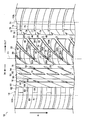
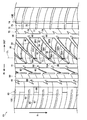
- FIG. 1 shows a tread 12 of a pneumatic tire 10.
- the tread 12 has a ground contact edge 12E, which is a pneumatic tire 10 mounted on a standard rim defined in JATMA YEAR BOOK (Japan Automobile Tire Association Standard, 2009 edition), and applicable size / prior rating in JATMA YEAR BOOK.
- JATMA YEAR BOOK Japan Automobile Tire Association Standard, 2009 edition
- JATMA YEAR BOOK Japan Automobile Tire Association Standard, 2009 edition
- the pneumatic tire 10 of the present embodiment has an asymmetric pattern shape with the tire equatorial plane CL in between.
- the left side of the drawing is the inside when the vehicle is mounted (indicated by an arrow IN), and the right side of the drawing is the vehicle when mounted. It is preferable to be mounted so as to be outside (indicated by an arrow OUT).
- the tire rotation direction is mounted so that the tire rotation direction is the direction indicated by the arrow R (the lower side in the figure is the stepping side and the upper side is the kicking side). Note that it is not always necessary to mount with the above-described directionality, and the IN-OUT of the embodiment may be mounted reversely, or the front-rear direction may be mounted reversely.
- a first circumferential groove 14 and a second circumferential groove 16 are a plurality of (three in the present embodiment) circumferential grooves extending along the tire circumferential direction. And the 3rd circumferential direction groove
- channel 18 is formed.
- the first circumferential groove 14 is arranged on one side of the tire equator plane CL (outside when the vehicle is mounted), and the second circumferential groove 16 and the third circumferential groove 18 are on the other side of the tire equator plane CL (vehicle It is arranged on the inner side). Further, the second circumferential groove 16 is disposed on the tire equatorial plane CL side with respect to the third circumferential groove 18.
- the first circumferential groove 14 is the outermost circumferential groove on the OUT side
- the third circumferential groove is the outermost circumferential groove on the IN side.
- a land portion 20 is formed between the first circumferential groove 14 and the second circumferential groove 16.
- a plurality of lug grooves 30 are formed in the circumferential direction so as to cross the first circumferential groove 14 and the second circumferential groove 16.
- the lug groove 30 extends from the first circumferential groove 14 toward the second circumferential groove 16 so as to incline to the left so that the inclination angle with respect to the tire equatorial plane gradually increases.
- the lug groove 30 has a shallow groove 30 ⁇ / b> A having a shallower groove bottom on the second circumferential groove 16 side than on the first circumferential groove 14 side.
- the shallow groove 30A is disposed closer to the second circumferential groove 16 than the tire equatorial plane CL.
- the shallow groove 30 ⁇ / b> A is not an essential configuration, and the lug groove 30 may be configured to have the same depth over the second circumferential groove 16.
- the lug groove 30 may have a length up to an intermediate portion in the tire width direction of the partition land portion 22 without being communicated with the second circumferential groove 16.
- the lug groove 30 is configured such that the groove width gradually increases from the first circumferential groove 14 side toward the second circumferential groove 16 side.
- the lug groove 30 has a curved shape in which the upper left side of the figure slightly bulges.
- the angle of the lug groove 30 with respect to the tire equatorial plane CL is in the range of 20 ° to 60 °. If the angle is less than 20 degrees, the section land portion 22 described later becomes longer in the tire circumferential direction, and there is a concern that the performance of the exercise is deteriorated. On the other hand, when the angle of the lug groove 30 with respect to the tire circumferential direction exceeds 60 degrees, there is no merit for drainage performance. Accordingly, it is preferable that the angle of the lug groove 30 with respect to the tire equatorial plane CL is in the range of 20 ° to 60 °.
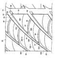
- a section land portion 22 is formed between the adjacent lug grooves 30, a section land portion 22 is formed.
- the corner 24 on the tire circumferential direction kicking side (upper side in the figure) of the section land portion 22 is an acute angle than the corner 26 on the stepping side (lower side in the figure).
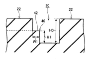
- a stepped portion 40 is formed facing the lug groove 30 on the corner portion 24 side of the land section 22.
- the step portion 40 has a step surface 42 that rises from the bottom of the lug groove 30 and has a step that is lower than the outermost surface in the tire radial direction of the land section 22.
- the stepped portion 40 is formed from the end portion of the partition land portion 22 on the first circumferential groove 14 side to the shallow groove 30A.
- the protruding width W1 of the stepped portion 40 to the lug groove 30 is preferably 10% to 50% of the average groove width of the lug groove 30.
- the protruding width of the stepped portion 40 to the lug groove 30 is preferably 10% to 50% of the average groove width of the lug groove 30.
- the height H1 of the stepped portion 40 from the bottom of the lug groove 30 is preferably 30% to 70% of the depth H0 of the lug groove 30 on the first circumferential groove 14 side. If the height of the lug groove 30 from the groove bottom is less than 30% of the depth of the lug groove 30 on the first circumferential groove 14 side, the fall of the section land portion 22 cannot be effectively suppressed. If the depth of the lug groove 30 on the first circumferential groove 14 side exceeds 70%, the merit for drainage performance in the lug groove 30 is lost. Therefore, the height H1 of the step portion 40 from the bottom of the lug groove 30 is preferably 30% to 70% of the depth H0 of the lug groove 30 on the first circumferential groove 14 side.
- the step surface 42 of the step portion 40 and the groove bottom of the shallow groove 30A are flush with each other.
- the section land portion 22 includes section shallow grooves 34 and 36 that connect adjacent lug grooves 30.
- the partition shallow grooves 34 and 36 are formed in an arc shape that is convex in the kicking-out direction, and are disposed substantially parallel to each other.
- the partition shallow grooves 34 and 36 are shallower than the depth of the lug groove 30 on the first circumferential groove 14 side, and the groove bottom is flush with the step surface 42.
- the partition land portion 22 is partitioned into a first block 22A, a second block 22B, and a third block 22C sequentially from the IN side by the partition shallow grooves 34 and 36.
- the first block 22A includes two sipes 38A-1 and 38A-2
- the second block 22B includes one sipes 38B
- the third block 22C includes one sipes 38C.
- the sipes 38A-1, 38A-2, 38B, and 38C are formed in an arc shape that is substantially parallel to the section shallow grooves 34 and 36 and is convex in the kick-out direction in the same manner as the section shallow grooves 34 and 36.
- the sipe 38A-1 is disposed so as to connect the second circumferential groove 16 and the lug groove 30 together.
- the sipes 38A-2 and 38B are arranged so as to connect the adjacent lug grooves 30 to each other.
- the sipe 38C is arranged so as to connect the lug groove 30 and the first circumferential groove 14.
- the acute angle portions 35 and 37 formed between the partition shallow grooves 34 and 36 and the lug groove 30 are chamfered. Further, the acute angle portion 39 formed between the lug groove 30 and the second circumferential groove 16 is also chamfered.
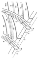
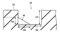
- a first protrusion 46 that protrudes into the first circumferential groove 14 is formed on the corner 24 side of the partition land portion 22.
- the first protrusion 46 has an inclined surface 48 that is inclined from the height of the step surface 42 toward the groove bottom of the first circumferential groove 14.
- the inclined surface 48 is formed so that the kick-out side is extended from the step surface 42, and the step-on side is formed so that the wall surface on the first circumferential groove 14 side of the partition land portion 22 protrudes.
- the first protrusion 46 has a triangular shape as viewed from the tire circumferential direction.
- the first protrusion 46 is inclined in the same direction as the lug groove 30 with respect to the tire equatorial plane CL when viewed from the tread side. Therefore, it has an overhang component not only in the tire width direction but also in the tire circumferential direction, so that not only the braking performance and traction performance on snow but also the cornering performance can be improved.
- the height H2 from the groove bottom on the wall surface side of the land section 22 of the first protrusion 46 is preferably 30% to 70% of the groove depth H5 of the first circumferential groove 14. If the height H2 of the first protrusion 46 is less than 30% of the groove depth H5 of the first circumferential groove 14, the performance on snow cannot be improved effectively. Further, if it exceeds 70% of the groove depth H5 of the first circumferential groove 14, it is impossible to efficiently achieve both drainage performance and performance on snow. Therefore, the height H2 of the first protrusion 46 from the groove bottom on the side of the land section 22 is preferably 30% to 70% of the groove depth H5 of the first circumferential groove 14. More preferably, the height H2 of the first protrusion 46 from the groove bottom on the section land portion 22 side is 40% to 60% of the groove depth H5 of the first circumferential groove 14.
- the overhanging width W2 of the first protrusion 46 to the first circumferential groove 14 is preferably 10% to 50% of the groove width W5 of the first circumferential groove 14. If the overhanging width W2 of the first protrusion 46 is less than 10% of the groove width W5 of the first circumferential groove 14, the performance on snow cannot be effectively improved. Further, if it exceeds 50% of the groove width W5 of the first circumferential groove 14, it is impossible to efficiently achieve both drainage performance and performance on snow. Accordingly, the overhang width W2 of the first protrusion 46 to the first circumferential groove 14 is preferably 10% to 50% of the groove width W5 of the first circumferential groove 14. Further, it is more preferable that the protruding width W2 of the first protrusion 46 to the first circumferential groove 14 is 40% to 50% of the groove width W5 of the first circumferential groove 14.
- the occupation ratio of the cross section in the same direction of the first protrusion 46 with respect to the groove cross section of the first circumferential groove 14 becomes 10% to 15%. .
- a second land portion 50 is formed between the second circumferential groove 16 and the third circumferential groove 18.
- the second land portion 50 is narrower in the tire width direction than the land portion 20.
- a sound absorbing cavity 52 is formed at the center of the second land portion 50 in the tire width direction.
- the sound absorbing cavity 52 is a long groove along the tire circumferential direction.
- the sound absorbing cavity 52 communicates with the sound absorbing shallow groove 54.
- the sound absorbing shallow groove 54 has one end connected to the stepped side end of the sound absorbing cavity 52 and the other end connected to the second circumferential groove 16.
- the sound absorbing shallow groove 54 is inclined with respect to the tire equatorial plane CL so that the second circumferential groove 16 side is disposed on the kicking side.
- a sipe 56 is formed on the opposite side of the sound absorption shallow groove 54 across the sound absorption cavity 52 of the second land portion 50.
- the sipe 56 is configured so that one end thereof communicates with the third circumferential groove 18 and the other end reaches the vicinity of the kicking side end of the sound absorbing cavity 52.
- the sipe 56 is inclined with respect to the tire equatorial plane CL in the same direction as the sound absorbing shallow groove 54 so that the third circumferential groove 18 side is disposed on the stepping side.
- the sipe 56 is not in communication with the sound absorbing cavity 52.
- the volume of the sound-absorbing cavity 52 and the cross-sectional area and length of the sound-absorbing shallow groove 54 are set so as to correspond to a predetermined noise frequency during traveling based on the Helmholtz resonance theory, thereby reducing noise at the frequency. Be able to.
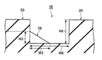
- a corner 51 is formed at a portion where the sound absorbing shallow groove 54 and the second circumferential groove 16 of the second land portion 50 intersect.
- the corner 51 is formed with a second protrusion 58 that protrudes into the second circumferential groove 16.
- the corner 51 is an acute angle and is chamfered.
- the second protrusion 58 is inclined toward the groove bottom of the second circumferential groove 16 from an intermediate portion of the wall surface of the second land portion 50 on the second circumferential groove 16 side.
- An inclined surface 59 is provided.
- the second protrusion 58 extends in the same direction as the sound absorbing shallow groove 54 and is inclined with respect to the tire equatorial plane CL.
- the second protrusion 58 has a triangular shape as viewed from the tire circumferential direction.
- the second protrusion 58 is inclined in the same direction as the sound absorbing shallow groove 54 with respect to the tire equatorial plane CL when viewed from the tread side. Therefore, it has an overhang component not only in the tire width direction but also in the tire circumferential direction, so that not only the braking performance and traction performance on snow but also the cornering performance can be improved.
- the height H3 of the second protrusion 58 from the groove bottom on the wall surface side of the second land portion 50 is preferably 30% to 70% of the groove depth H6 of the second circumferential groove 16. If the height H3 of the second protrusion 58 is less than 30% of the groove depth H6 of the second circumferential groove 16, the performance on snow cannot be effectively improved. Moreover, if it exceeds 70% of the groove depth H6 of the 2nd circumferential direction groove
- the overhanging width W3 of the second protrusion 58 to the second circumferential groove 16 is preferably 10% to 50% of the groove width W6 of the second circumferential groove 16. If the overhang width W3 of the second protrusion 58 is less than 10% of the groove width W6 of the second circumferential groove 16, the performance on snow cannot be effectively improved. Further, if it exceeds 50% of the groove width W6 of the second circumferential groove 16, it is impossible to efficiently achieve both drainage performance and performance on snow. Therefore, the overhanging width W3 of the second protrusion 58 to the second circumferential groove 16 is preferably 10% to 50% of the groove width W6 of the second circumferential groove 16.
- the height H3 of the second protrusion 58 from the bottom of the wall surface of the second land portion 50 is more preferably 40% to 60% of the groove depth H6 of the second circumferential groove 16. .
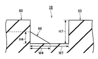
- An in-side shoulder land portion 60 is formed on the shoulder side of the third circumferential groove 18.
- a sipe 62 that is continuous in the tire circumferential direction is formed at the center in the tire width direction of the in-side shoulder land portion 60.
- a sipe 64 is formed between the sipe 62 and the third circumferential groove 18. The sipe 64 communicates with the sipe 62 and the third circumferential groove 18 and is disposed in a direction substantially parallel to the sipe 56 of the second land portion 50. Further, the sipe 64 is disposed at a position where the end portion on the third circumferential groove 18 side corresponds to the end portion of the sipe 56 on the third circumferential groove 18 side.
- a corner portion 61 is formed at a portion where the sipe 64 of the in-side shoulder land portion 60 and the third circumferential groove 18 intersect.
- the corner portion 61 is formed with a third protrusion 66 that protrudes into the third circumferential groove 18.
- the corner 61 is an acute angle and is chamfered.
- the third protrusion 66 is inclined from the middle portion of the wall surface on the third circumferential groove 18 side of the in-side shoulder land portion 60 toward the groove bottom of the third circumferential groove 18.
- An inclined surface 68 is provided.
- the third protrusion 66 extends in the same direction as the sipe 64 and is inclined with respect to the tire equatorial plane CL.
- the third protrusion 66 has a triangular shape as viewed from the tire circumferential direction.
- the third protrusion 66 is inclined in the same direction as the sipe 64 with respect to the tire equatorial plane CL when viewed from the tread side. Therefore, it has an overhang component not only in the tire width direction but also in the tire circumferential direction, so that not only the braking performance and traction performance on snow but also the cornering performance can be improved.
- An end shallow groove 63 is formed on the shoulder side of the sipe 62.
- the end shallow groove 63 is disposed so as to extend in the tire width direction.
- Two sipes 65 and 67 are formed between the adjacent end shallow grooves 63.
- the sipes 65 and 67 are connected by a sipe 69 disposed in the tire circumferential direction.
- the height H4 from the groove bottom on the wall surface side of the in-side shoulder land portion 60 of the third protrusion 66 is preferably 30% to 70% of the groove depth H7 of the third circumferential groove 18. If the height H4 of the third protrusion 66 is less than 30% of the groove depth H7 of the third circumferential groove 18, the performance on snow cannot be improved effectively. Further, if it exceeds 70% of the groove depth H7 of the third circumferential groove 18, it is impossible to efficiently achieve both drainage performance and performance on snow. Accordingly, the height H4 from the groove bottom on the wall surface side of the in-side shoulder land portion 60 of the third protrusion 66 is preferably 30% to 70% of the groove depth H7 of the third circumferential groove 18. The height H4 from the groove bottom on the wall surface side of the in-side shoulder land portion 60 of the third protrusion 66 is preferably 30% to 70% of the groove depth H7 of the third circumferential groove 18; Furthermore, 40% to 60% is more preferable.
- the overhanging width W4 of the third protrusion 66 to the third circumferential groove 18 is preferably 10% to 50% of the groove width W7 of the third circumferential groove 18. If the overhang width W4 of the third protrusion 66 is less than 10% of the groove width W7 of the third circumferential groove 18, the performance on snow cannot be improved effectively. Further, if it exceeds 50% of the groove width W7 of the third circumferential groove 18, it is impossible to efficiently achieve both drainage performance and performance on snow. Therefore, the overhanging width W4 of the third protrusion 66 to the third circumferential groove 18 is preferably 10% to 50% of the groove width W7 of the third circumferential groove 18. Further, the overhanging width W4 of the third protrusion 66 to the third circumferential groove 18 is more preferably 40% to 50% of the groove width W7 of the third circumferential groove 18.
- the occupation ratio of the cross section in the same direction of the second protrusion 66 with respect to the groove cross section of the third circumferential groove 18 is 10% to 15%.
- An out-side shoulder land portion 70 is formed on the shoulder side of the first circumferential groove 14. Sipes 72 and 74 that are continuous in the tire circumferential direction are separated from each other at the center in the tire width direction of the outer shoulder land portion 70.
- An end shallow groove 73 is formed slightly from the sipe 72 toward the shoulder side from the first circumferential groove 14 side.
- the end shallow groove 73 is disposed so as to extend in the tire width direction.
- a sipe 75 is formed between adjacent end shallow grooves 73.
- Sipes 76 and 77 are formed between the sipe 72 and the first circumferential groove 14.
- the sipe 76 is formed in the same direction as the end shallow groove 73 on the extension of the end shallow groove 73.
- One end of the sipe 77 communicates with the end of the sipe 75 and the sipe 72, the other end communicates with the first circumferential groove 14, and is disposed in a direction substantially parallel to the lug groove 30.
- a notch 79 is formed at a position corresponding to the lug groove 30 on the first circumferential groove 14 side of the outer shoulder land portion 70.
- the tread 12 is provided with three circumferential grooves including a first circumferential groove 14, a second circumferential groove 16, and a third circumferential groove 18 extending along the tire circumferential direction.
- the lug groove 30 inclined at an angle of 20 ° to 60 ° with respect to the tire circumferential direction is disposed on the tread 12, higher drainage performance than the conventional all-season tire can be exhibited. Furthermore, noise can be suppressed.
- the lug groove 30 is comprised so that a groove width may become wide toward the 1st circumferential direction groove
- the lug groove 30 is curved in the direction in which the inclination angle with respect to the tire equatorial plane gradually increases toward the first circumferential groove 14 side (the direction in which the angle of the corner portion 24 increases). Compared to the case, the distance from the lug groove 30 toward the first circumferential groove 14 can be shortened, and the drainage can be improved.
- the level difference part 40 is formed in the division land part 22 facing the lug groove 30 on the corner part 24 side, the rigidity of the division land part 22 is ensured while ensuring drainage performance in the lug groove 30. It is possible to improve and suppress collapse.
- the stepped portion 40 is formed only on the corner portion 24 side, but a stepped portion having the same configuration as the stepped portion 40 may be formed on the stepped side end of the land section 22. .
- the second circumferential groove 16 side of the lug groove 30 a shallow groove 30A having a shallower groove bottom than the first circumferential groove 14 side, a portion close to the tire equatorial plane CL of the tread 12 (the contact pressure) By increasing the strength of the high portion), the strength of the land section 22 can be effectively increased.
- the cornering performance, brake performance, and traction performance on snow can be improved.
- the division shallow grooves 34 and 36 are formed in an arc shape, a long communication groove can be formed as compared with the case of a straight shape, and cornering performance, braking performance, and traction performance on snow can be obtained. Can be increased.
- the partition shallow grooves 34 and 36 are configured to be shallower than the depth of the lug groove 30 on the first circumferential groove 14 side. It may be the same depth.
- the edge can be formed while ensuring the rigidity of the land section 22.
- the first protrusion 46 and the second protrusion 58 are provided in each of the first circumferential groove 14, the second circumferential groove 16, and the third circumferential groove 18 that extend along the tire circumferential direction. Since the third protrusion 66 is provided, the traction performance and the braking performance on snow can be improved as compared with the case without these protrusions. At the same time, the groove volume of the first circumferential groove 14, the second circumferential groove 16, and the third circumferential groove 18 can be secured, and the drainage can be secured.
- the rigidity of the corner 24 can be reinforced.
- first protrusion 46, the second protrusion 58, and the third protrusion 66 are provided in each of the first circumferential groove 14, the second circumferential groove 16, and the third circumferential groove 18.
- any one or two of the grooves may be provided with protrusions.
- the sound absorption groove 52 is formed in the second land portion 50, a higher noise suppression effect can be obtained.
- the tire size was 225 / 45R17 in all cases. From Table 1, it is clear that the pneumatic tires of the examples have high performance in terms of snow performance and steering stability performance.
- Comparative Examples 1 to 9 have high performance on snow, but have a low drainage index of 97.0 or less. In Examples 1 to 4, it was possible to obtain a high evaluation for the performance on snow while maintaining the drainage performance at 98.0 or more.
Landscapes
- Engineering & Computer Science (AREA)
- Mechanical Engineering (AREA)
- Tires In General (AREA)
Abstract
Priority Applications (3)
| Application Number | Priority Date | Filing Date | Title |
|---|---|---|---|
| US13/581,133 US9481210B2 (en) | 2010-02-26 | 2011-02-17 | Pneumatic tire |
| EP11747245.6A EP2540526B1 (fr) | 2010-02-26 | 2011-02-17 | Bandage pneumatique |
| CN201180011175.7A CN102770286B (zh) | 2010-02-26 | 2011-02-17 | 充气轮胎 |
Applications Claiming Priority (6)
| Application Number | Priority Date | Filing Date | Title |
|---|---|---|---|
| JP2010-042156 | 2010-02-26 | ||
| JP2010-042155 | 2010-02-26 | ||
| JP2010042155A JP5489782B2 (ja) | 2010-02-26 | 2010-02-26 | 空気入りタイヤ |
| JP2010042156A JP5461233B2 (ja) | 2010-02-26 | 2010-02-26 | 空気入りタイヤ |
| JP2010-042154 | 2010-02-26 | ||
| JP2010042154A JP5419752B2 (ja) | 2010-02-26 | 2010-02-26 | 空気入りタイヤ |
Publications (1)
| Publication Number | Publication Date |
|---|---|
| WO2011105281A1 true WO2011105281A1 (fr) | 2011-09-01 |
Family
ID=44506693
Family Applications (1)
| Application Number | Title | Priority Date | Filing Date |
|---|---|---|---|
| PCT/JP2011/053394 WO2011105281A1 (fr) | 2010-02-26 | 2011-02-17 | Bandage pneumatique |
Country Status (4)
| Country | Link |
|---|---|
| US (1) | US9481210B2 (fr) |
| EP (1) | EP2540526B1 (fr) |
| CN (1) | CN102770286B (fr) |
| WO (1) | WO2011105281A1 (fr) |
Cited By (1)
| Publication number | Priority date | Publication date | Assignee | Title |
|---|---|---|---|---|
| JP2013139166A (ja) * | 2011-12-28 | 2013-07-18 | Sumitomo Rubber Ind Ltd | 空気入りタイヤ |
Families Citing this family (10)
| Publication number | Priority date | Publication date | Assignee | Title |
|---|---|---|---|---|
| JP6012397B2 (ja) * | 2012-10-24 | 2016-10-25 | 株式会社ブリヂストン | 空気入りタイヤ |
| DE102014220977A1 (de) * | 2014-10-16 | 2016-04-21 | Continental Reifen Deutschland Gmbh | Fahrzeugluftreifen |
| JP6434857B2 (ja) * | 2015-05-12 | 2018-12-05 | 住友ゴム工業株式会社 | 空気入りタイヤ |
| JP6663684B2 (ja) * | 2015-10-30 | 2020-03-13 | Toyo Tire株式会社 | 空気入りタイヤ |
| US20170157990A1 (en) * | 2015-12-08 | 2017-06-08 | The Goodyear Tire & Rubber Company | Pneumatic tire |
| JP6902335B2 (ja) * | 2016-06-13 | 2021-07-14 | 株式会社ブリヂストン | タイヤ |
| CN109476181B (zh) * | 2016-08-02 | 2021-06-22 | 横滨橡胶株式会社 | 充气轮胎 |
| DE102018220894A1 (de) | 2018-12-04 | 2020-06-04 | Continental Reifen Deutschland Gmbh | Fahrzeugreifen |
| JP7275834B2 (ja) * | 2019-05-14 | 2023-05-18 | 住友ゴム工業株式会社 | タイヤ |
| EP3744537B1 (fr) * | 2019-05-31 | 2021-12-08 | Sumitomo Rubber Industries, Ltd. | Pneumatique |
Citations (10)
| Publication number | Priority date | Publication date | Assignee | Title |
|---|---|---|---|---|
| JPS6116111A (ja) * | 1984-06-30 | 1986-01-24 | Yokohama Rubber Co Ltd:The | 空気入りタイヤ |
| JPH0322953A (ja) | 1989-06-20 | 1991-01-31 | Kikkoman Corp | 味付け豆腐の製造法 |
| JPH09207521A (ja) * | 1996-01-30 | 1997-08-12 | Sumitomo Rubber Ind Ltd | 空気入りタイヤ |
| JPH11321240A (ja) * | 1997-12-04 | 1999-11-24 | Continental Ag | 冬用タイヤのトレッドパターン |
| JP3222953B2 (ja) | 1992-11-05 | 2001-10-29 | 横浜ゴム株式会社 | 空気入りタイヤ |
| JP2003154812A (ja) * | 2001-11-21 | 2003-05-27 | Toyo Tire & Rubber Co Ltd | 空気入りタイヤ |
| JP2004017863A (ja) * | 2002-06-18 | 2004-01-22 | Sumitomo Rubber Ind Ltd | 空気入りタイヤ |
| JP2004284577A (ja) * | 2003-03-20 | 2004-10-14 | Continental Ag | トレッド条片プロフィルを有する車両用タイヤ、特に冬期用タイヤ |
| WO2007072824A1 (fr) * | 2005-12-21 | 2007-06-28 | Bridgestone Corporation | Pneu |
| JP2008044441A (ja) * | 2006-08-11 | 2008-02-28 | Bridgestone Corp | 空気入りタイヤ |
Family Cites Families (11)
| Publication number | Priority date | Publication date | Assignee | Title |
|---|---|---|---|---|
| JPH0796716A (ja) | 1993-09-29 | 1995-04-11 | Yokohama Rubber Co Ltd:The | 重荷重用空気入りタイヤ |
| DE29825135U1 (de) | 1997-12-04 | 2005-05-19 | Continental Aktiengesellschaft | Laufflächenprofil eines Winterreifens |
| DE19957915B4 (de) | 1999-12-02 | 2005-08-11 | Continental Aktiengesellschaft | Fahrzeugluftreifen |
| JP4275283B2 (ja) * | 2000-02-16 | 2009-06-10 | 株式会社ブリヂストン | 空気入りタイヤ |
| JP4065718B2 (ja) | 2002-05-09 | 2008-03-26 | 株式会社ブリヂストン | 空気入りタイヤ |
| JP4776152B2 (ja) | 2003-08-05 | 2011-09-21 | 株式会社ブリヂストン | 空気入りタイヤ |
| JP4268034B2 (ja) * | 2003-12-26 | 2009-05-27 | 株式会社ブリヂストン | 空気入りタイヤ |
| JP4580387B2 (ja) * | 2004-05-27 | 2010-11-10 | 株式会社ブリヂストン | 空気入りタイヤ |
| JP4764085B2 (ja) * | 2005-07-22 | 2011-08-31 | 株式会社ブリヂストン | 空気入りタイヤ |
| JP4785490B2 (ja) | 2005-10-18 | 2011-10-05 | 株式会社ブリヂストン | タイヤトレッドの傾斜溝構造 |
| KR101096990B1 (ko) * | 2006-12-20 | 2011-12-20 | 가부시키가이샤 브리지스톤 | 공기입 타이어 |
-
2011
- 2011-02-17 US US13/581,133 patent/US9481210B2/en not_active Expired - Fee Related
- 2011-02-17 CN CN201180011175.7A patent/CN102770286B/zh not_active Expired - Fee Related
- 2011-02-17 WO PCT/JP2011/053394 patent/WO2011105281A1/fr active Application Filing
- 2011-02-17 EP EP11747245.6A patent/EP2540526B1/fr not_active Not-in-force
Patent Citations (10)
| Publication number | Priority date | Publication date | Assignee | Title |
|---|---|---|---|---|
| JPS6116111A (ja) * | 1984-06-30 | 1986-01-24 | Yokohama Rubber Co Ltd:The | 空気入りタイヤ |
| JPH0322953A (ja) | 1989-06-20 | 1991-01-31 | Kikkoman Corp | 味付け豆腐の製造法 |
| JP3222953B2 (ja) | 1992-11-05 | 2001-10-29 | 横浜ゴム株式会社 | 空気入りタイヤ |
| JPH09207521A (ja) * | 1996-01-30 | 1997-08-12 | Sumitomo Rubber Ind Ltd | 空気入りタイヤ |
| JPH11321240A (ja) * | 1997-12-04 | 1999-11-24 | Continental Ag | 冬用タイヤのトレッドパターン |
| JP2003154812A (ja) * | 2001-11-21 | 2003-05-27 | Toyo Tire & Rubber Co Ltd | 空気入りタイヤ |
| JP2004017863A (ja) * | 2002-06-18 | 2004-01-22 | Sumitomo Rubber Ind Ltd | 空気入りタイヤ |
| JP2004284577A (ja) * | 2003-03-20 | 2004-10-14 | Continental Ag | トレッド条片プロフィルを有する車両用タイヤ、特に冬期用タイヤ |
| WO2007072824A1 (fr) * | 2005-12-21 | 2007-06-28 | Bridgestone Corporation | Pneu |
| JP2008044441A (ja) * | 2006-08-11 | 2008-02-28 | Bridgestone Corp | 空気入りタイヤ |
Non-Patent Citations (1)
| Title |
|---|
| See also references of EP2540526A4 * |
Cited By (1)
| Publication number | Priority date | Publication date | Assignee | Title |
|---|---|---|---|---|
| JP2013139166A (ja) * | 2011-12-28 | 2013-07-18 | Sumitomo Rubber Ind Ltd | 空気入りタイヤ |
Also Published As
| Publication number | Publication date |
|---|---|
| EP2540526A4 (fr) | 2015-11-18 |
| EP2540526A1 (fr) | 2013-01-02 |
| CN102770286B (zh) | 2015-12-16 |
| EP2540526B1 (fr) | 2017-04-05 |
| US20120318419A1 (en) | 2012-12-20 |
| US9481210B2 (en) | 2016-11-01 |
| CN102770286A (zh) | 2012-11-07 |
Similar Documents
| Publication | Publication Date | Title |
|---|---|---|
| WO2011105281A1 (fr) | Bandage pneumatique | |
| JP4506869B2 (ja) | 空気入りタイヤ | |
| JP5321093B2 (ja) | 空気入りタイヤ | |
| KR101788883B1 (ko) | 공기 타이어 | |
| US10836215B2 (en) | Tire | |
| JP3930391B2 (ja) | 空気入りタイヤ | |
| JP6772599B2 (ja) | 空気入りタイヤ | |
| JP4213197B1 (ja) | 空気入りタイヤ | |
| WO2015087572A1 (fr) | Pneu | |
| US20170008346A1 (en) | Pneumatic tire | |
| WO2016194287A1 (fr) | Pneumatique | |
| JP2010247759A (ja) | 空気入りタイヤ | |
| EP3115229B1 (fr) | Pneu pour fonctionnement intensif | |
| KR20160005791A (ko) | 공기입 타이어 | |
| JP6450261B2 (ja) | 空気入りタイヤ | |
| US20100089509A1 (en) | pneumatic tire | |
| JP6769181B2 (ja) | タイヤ | |
| EP2990230B1 (fr) | Bandage pneumatique | |
| JP5419752B2 (ja) | 空気入りタイヤ | |
| JP6139843B2 (ja) | 空気入りタイヤ | |
| JP4268034B2 (ja) | 空気入りタイヤ | |
| JP6607708B2 (ja) | 空気入りタイヤ | |
| JP5282479B2 (ja) | 空気入りタイヤ | |
| JP6416024B2 (ja) | 空気入りタイヤ | |
| JP5461233B2 (ja) | 空気入りタイヤ |
Legal Events
| Date | Code | Title | Description |
|---|---|---|---|
| WWE | Wipo information: entry into national phase |
Ref document number: 201180011175.7 Country of ref document: CN |
|
| 121 | Ep: the epo has been informed by wipo that ep was designated in this application |
Ref document number: 11747245 Country of ref document: EP Kind code of ref document: A1 |
|
| WWE | Wipo information: entry into national phase |
Ref document number: 13581133 Country of ref document: US |
|
| NENP | Non-entry into the national phase |
Ref country code: DE |
|
| REEP | Request for entry into the european phase |
Ref document number: 2011747245 Country of ref document: EP |
|
| WWE | Wipo information: entry into national phase |
Ref document number: 2011747245 Country of ref document: EP |