WO2011104909A1 - 回転電機システム - Google Patents
回転電機システム Download PDFInfo
- Publication number
- WO2011104909A1 WO2011104909A1 PCT/JP2010/064279 JP2010064279W WO2011104909A1 WO 2011104909 A1 WO2011104909 A1 WO 2011104909A1 JP 2010064279 W JP2010064279 W JP 2010064279W WO 2011104909 A1 WO2011104909 A1 WO 2011104909A1
- Authority
- WO
- WIPO (PCT)
- Prior art keywords
- electrical machine
- rotating electrical
- stator
- cooling passage
- cooling
- Prior art date
- Legal status (The legal status is an assumption and is not a legal conclusion. Google has not performed a legal analysis and makes no representation as to the accuracy of the status listed.)
- Ceased
Links
Images



Classifications
-
- G—PHYSICS
- G06—COMPUTING OR CALCULATING; COUNTING
- G06F—ELECTRIC DIGITAL DATA PROCESSING
- G06F16/00—Information retrieval; Database structures therefor; File system structures therefor
- G06F16/10—File systems; File servers
- G06F16/17—Details of further file system functions
- G06F16/178—Techniques for file synchronisation in file systems
-
- H—ELECTRICITY
- H02—GENERATION; CONVERSION OR DISTRIBUTION OF ELECTRIC POWER
- H02K—DYNAMO-ELECTRIC MACHINES
- H02K5/00—Casings; Enclosures; Supports
- H02K5/04—Casings or enclosures characterised by the shape, form or construction thereof
- H02K5/22—Auxiliary parts of casings not covered by groups H02K5/06-H02K5/20, e.g. shaped to form connection boxes or terminal boxes
- H02K5/225—Terminal boxes or connection arrangements
-
- G—PHYSICS
- G06—COMPUTING OR CALCULATING; COUNTING
- G06F—ELECTRIC DIGITAL DATA PROCESSING
- G06F16/00—Information retrieval; Database structures therefor; File system structures therefor
- G06F16/10—File systems; File servers
- G06F16/13—File access structures, e.g. distributed indices
-
- G—PHYSICS
- G06—COMPUTING OR CALCULATING; COUNTING
- G06F—ELECTRIC DIGITAL DATA PROCESSING
- G06F16/00—Information retrieval; Database structures therefor; File system structures therefor
- G06F16/10—File systems; File servers
- G06F16/17—Details of further file system functions
- G06F16/174—Redundancy elimination performed by the file system
- G06F16/1748—De-duplication implemented within the file system, e.g. based on file segments
-
- G—PHYSICS
- G06—COMPUTING OR CALCULATING; COUNTING
- G06F—ELECTRIC DIGITAL DATA PROCESSING
- G06F16/00—Information retrieval; Database structures therefor; File system structures therefor
- G06F16/10—File systems; File servers
- G06F16/18—File system types
- G06F16/182—Distributed file systems
- G06F16/184—Distributed file systems implemented as replicated file system
- G06F16/1844—Management specifically adapted to replicated file systems
-
- H—ELECTRICITY
- H02—GENERATION; CONVERSION OR DISTRIBUTION OF ELECTRIC POWER
- H02K—DYNAMO-ELECTRIC MACHINES
- H02K11/00—Structural association of dynamo-electric machines with electric components or with devices for shielding, monitoring or protection
- H02K11/30—Structural association with control circuits or drive circuits
- H02K11/33—Drive circuits, e.g. power electronics
-
- H—ELECTRICITY
- H02—GENERATION; CONVERSION OR DISTRIBUTION OF ELECTRIC POWER
- H02K—DYNAMO-ELECTRIC MACHINES
- H02K5/00—Casings; Enclosures; Supports
- H02K5/04—Casings or enclosures characterised by the shape, form or construction thereof
- H02K5/20—Casings or enclosures characterised by the shape, form or construction thereof with channels or ducts for flow of cooling medium
- H02K5/203—Casings or enclosures characterised by the shape, form or construction thereof with channels or ducts for flow of cooling medium specially adapted for liquids, e.g. cooling jackets
-
- H—ELECTRICITY
- H02—GENERATION; CONVERSION OR DISTRIBUTION OF ELECTRIC POWER
- H02K—DYNAMO-ELECTRIC MACHINES
- H02K9/00—Arrangements for cooling or ventilating
- H02K9/22—Arrangements for cooling or ventilating by solid heat conducting material embedded in, or arranged in contact with, the stator or rotor, e.g. heat bridges
- H02K9/227—Heat sinks
-
- H—ELECTRICITY
- H05—ELECTRIC TECHNIQUES NOT OTHERWISE PROVIDED FOR
- H05K—PRINTED CIRCUITS; CASINGS OR CONSTRUCTIONAL DETAILS OF ELECTRIC APPARATUS; MANUFACTURE OF ASSEMBLAGES OF ELECTRICAL COMPONENTS
- H05K7/00—Constructional details common to different types of electric apparatus
- H05K7/20—Modifications to facilitate cooling, ventilating, or heating
- H05K7/2089—Modifications to facilitate cooling, ventilating, or heating for power electronics, e.g. for inverters for controlling motor
- H05K7/20927—Liquid coolant without phase change
Definitions
- the present invention relates to a structure of a rotating electric machine (rotating electric machine system) integrated with a power converter.
- a rotating electric machine and a power converter are generally mounted separately. Considering their mounting space in the vehicle and the optimal cooling method for each component, it is often convenient to install them separately. However, considering reduction in the number of parts and countermeasures against surges between the rotating electrical machine and the power converter, it is desirable that they are integrated.
- Patent Document 1 discloses an inverter-integrated rotating electrical machine, but there is a problem that the entire apparatus becomes large because a configuration such as a cooling water tank is employed.
- the present invention provides a technique for downsizing a rotating electric machine (rotating electric machine system) integrated with a power converter without reducing performance.
- a rotating electrical machine system is held by a rotating electrical machine having a stator and a rotor provided in the stator via a gap, a housing that holds the stator, and the housing.
- a power conversion device that drives the rotating electrical machine, and a first cooling passage that is provided in a housing portion between the stator and the power conversion device and in which a refrigerant that cools the stator and the power conversion device flows.
- the power conversion device has a power module that houses a power semiconductor element, the power module has a heat radiation fin, and the heat radiation fin protrudes from the opening between the power module and the first cooling passage toward the refrigerant side. Yes.
- the second casing is provided in the outer casing portion of the stator so as to circulate in the rotational direction of the rotating electrical machine, and the refrigerant flows.
- the second cooling passage communicates with the first cooling passage so that the refrigerant after cooling the power converter cools the stator.
- the first cooling passage has a shape that changes the flow direction of the refrigerant, and the second cooling passage is the first cooling passage.
- the refrigerant after cooling the power converter communicates so as to cool the stator, and in the communicating portion, the cross-sectional area of the second cooling passage is more than the cross-sectional area of the first cooling passage. It is preferable to communicate so that it may become large.
- the power module stores the power semiconductor elements in two rows, and the refrigerant is arranged in the first row in the first cooling passage. It is preferable to cool the power semiconductor elements arranged in the second row by changing the flow direction after cooling the power semiconductor elements.
- a rotating electrical machine system in the rotating electrical machine system according to the first aspect, it is preferable to have a temperature sensor in the vicinity of the radiation fin and control the cooling based on temperature data acquired by the temperature sensor.
- a rotating electrical machine system includes a rotating electrical machine having a stator and a rotor provided on the stator so as to rotate via a rotating gap, and a housing that holds the stator. And a first cooling passage that is provided in a housing portion between the stator and the power conversion device and that cools the power conversion device with a refrigerant flowing through the passage, and the stator.
- a second cooling passage that cools the stator by circulating in the rotation direction of the rotating electrical machine, and the first cooling passage flows through the first cooling passage.
- the second cooling passage communicates with the first cooling passage so that the refrigerant after cooling the power conversion device cools the stator, and the second cooling passage has a first cooling passage.
- Cross section of one cooling passage Also communicates to it is larger in cross-sectional area of the second cooling passage.
- the power conversion device includes a power module that houses the power semiconductor elements arranged in two rows, and in the first cooling passage, the refrigerant is It is preferable to cool the power semiconductor elements arranged in the second row by changing the flow direction after cooling the power semiconductor elements arranged in the first row.
- the heat dissipation plate of the power module has a heat dissipation fin, and the heat dissipation fin has an opening between the power module and the first cooling passage. It preferably projects from the refrigerant side to the refrigerant side.
- the temperature sensor is provided in the vicinity of the heat radiating fin and the cooling is controlled based on the temperature data acquired by the temperature sensor.
- the power converter using the direct water cooling method has a lower thermal resistance than general indirect water cooling, the area required for cooling the power semiconductor element can be reduced.
- the water path is shared, and the power converter can be cooled by the direct cooling method, thereby realizing a rotating electrical machine system including a small power converter. .
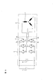
- FIG. 5 shows the main circuit of the present embodiment, and shows how the main components are electrically connected.
- the power converter is referred to as an inverter
- the rotating electrical machine is referred to as a motor.
- the rotating electrical machine can function not only as a motor but also as a generator.
- the motor includes a stator and a rotor (not shown) provided on the stator so as to rotate via a rotation gap.
- the inverter is held by a housing that holds the stator and drives the motor.
- FIG. 5 A portion surrounded by a wavy line corresponds to the inverter-integrated motor 1 described in the present embodiment, which is roughly divided into an inverter unit 2 and a motor unit 3.
- the inverter unit 2 converts electrical input (direct current) from the battery 4 connected from the outside into alternating current by regularly switching the power semiconductor element 5, and is sent to the motor unit 3.
- the electric circuit of FIG. 5 is drawn with the impedance 7 of the motor winding, and the alternating current converted by the inverter passes through the impedance 8 of the motor.
- the power semiconductor element 5 of the present embodiment is assumed to be an IGBT (Insulated Gate Bipolar Transistor), but another power semiconductor element (for example, a MOS-FET) is selected depending on a necessary frequency and voltage.
- IGBT Insulated Gate Bipolar Transistor
- MOS-FET complementary metal-oxide-semiconductor
- three IGBTs 5a and flywheel diodes 6a are provided on the positive electrode side (upper arm side), and the same number of IGBTs 5b and flywheel diodes 6b are provided on the negative electrode side (lower arm side). It corresponds.
- the pulsation (ripple) of the voltage generated at the time of switching is smoothed by the smoothing capacitor 21 located between the battery 4 and the power semiconductor element 5 group.
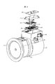
- FIG. 1 The rectangular parallelepiped portion at the top of FIG. 1 is the inverter portion 2, and the cylindrical portion at the bottom is the motor portion 3.
- the inverter part 2 and the motor part 3 are integrated by sharing one metal housing (outer housing 10). That is, the upper part of the outer housing 10 is the inverter part 2.
- the interior of the inverter unit 2 is an inverter chamber 13 in which components for realizing the inverter function are stored. Although the illustration is omitted so that the inside can be seen, in practice, a cover is attached to the top of the inverter portion so that foreign matter and moisture do not enter the inverter chamber 13.
- an inner housing 11 is provided inside the outer housing 10 of the motor unit 3 and a motor coil 14 is provided inside the inner housing 11.
- the outer housing 10 has a flange 12 so as to be attached to a vehicle engine, a transmission, a gear box, or the like.
- a bolt hole for attachment is arbitrarily formed in the flange 12.
- a motor control board 20 that controls the motor from the upper stage, a smoothing capacitor 21 that smoothes voltage ripples, and commands from the motor control board.
- the gate drive substrate 22 that receives and controls the on / off of the switching element, and the power module 23 that houses the power semiconductor element 5 are arranged so as to overlap the lowermost part of the inverter unit.
- the inverter according to the present embodiment is provided with a discharge resistor 25, and the charge accumulated in the smoothing capacitor 21 when the inverter is turned off is discharged by the discharge resistor 25.
- a signal connector 26 is provided on the outer wall of the inverter chamber 13 for exchanging signals with the vehicle side. The signal connector 26 is connected to one of the flat cables 27 inside the wall of the inverter chamber 13. One is connected to the motor control board 20.
- DC power from the external battery 4 is input from a high voltage connector 28 disposed at one end of the inverter unit 2.
- the direct current power is transmitted to the direct current terminal 55 of the power module 23, converted into alternating current by the power module 23, and transmitted from the alternating current terminal 56 of the power module 23 to the coil 14 through the lead wire 17.
- the alternating current is connected to the coil 14 through the current sensor 24.
- the AC current passing therethrough is detected by the current sensor 24, and the current value is transmitted to the motor control board 20 for use in controlling the motor.
- the connection line between the lead wire 17 and the power module 23 is designed to be as short as possible in order to suppress the influence of surge and noise.
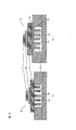
- FIG. 6 is a schematic diagram of the vertical structure of the power module 23, and FIGS. 10 and 11 are detailed external views of the power module 23.
- FIG. A heat radiating plate 42 is provided at the lower part of the power module 23 to release heat generated by the power semiconductor element 5 inside the power module 23 during switching, and a heat radiating fin 43 is disposed on the lower surface thereof.
- the fin 43 of this Embodiment has arranged the column-shaped pin fin in multiple numbers, a fin shape may be another shape.
- the power module 23 is fixed by fastening the bolt 57 with the bolt hole 36 so as to cover the opening 35 opened on the floor of the inverter chamber 13. At this time, the fin 43 is lowered from the opening 35. Protrusively.
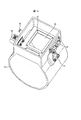
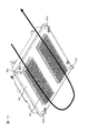
- FIG. 7 shows only the inner housing 11.
- a strip-shaped recess that is long in the circumferential direction on the surface is a cooling flow path 37. This extends over the inner housing so as to go around in a strip shape.
- the outer housing 10 forms a cover for the cooling flow path 37.
- a flow path inlet 39 is disposed under the inlet pipe 15 and is omitted in the drawing, but an O-ring or liquid is used so as to go around the inner housing in parallel with both sides of the cooling flow path 37. Inserting a seal makes it possible to take measures to prevent water leakage.
- the fins 43 of the power module 23 protrude from the opening 35 and, at the same time, protrude on the flat surface 38 of the cooling channel 37.
- the heat generated by the power semiconductor element 5 reaches the fins 43 integrated with the plates via the heat dissipation plate 42, and the fins 43 are directly cooled to cool the power semiconductor elements.
- the direct water cooling method will be adopted.
- water cooling with cooling water is assumed, but the cooling medium may be other than water.
- FIG. 6 schematically shows the vertical structure inside the power module 23 for comparison between direct water cooling and indirect water cooling.
- (A) is direct water cooling and
- (b) is indirect water cooling.
- the internal vertical structure of a general power module 23 is composed of a power semiconductor element 5, an insulating substrate 45, and a heat sink 42 in order from the top.
- the fin 43 is provided on the water channel side of the case inner wall 47 of the inverter case 46, and the power module 23 is installed on the surface of the case inner wall 47 facing the fin 43.
- a heat radiating grease 48 is generally applied between the heat radiating plate 42 of the power module and the inner wall 47 of the inverter case, which contributes to improvement of heat conduction on the surface where the metal and the metal are combined. That is, the power semiconductor element 5 radiates heat from the heat radiating plate 42 to the cooling water 44 via the heat radiating grease 48 and the inverter case inner wall 47.
- the position where the power module 23 is mounted is fixed to the inverter case 46 in the same manner as in the indirect water cooling.
- the mounting surface has an opening, and the power module covers the opening with the heat sink 42. Mounted on. That is, when the heat sink 42 has the fins 43, the fins 43 protrude from the opening to the cooling water side, and the cooling water 44 directly hits the heat sink 42 and the fins 43, so that the power semiconductor element 5 I'm drawing the heat.
- the thermal resistance from the power semiconductor element (IGBT) 5 to the cooling water 44 is about 0.15 ° C./W by indirect water cooling and about 0.09 ° C./W by direct water cooling.
- indirect water cooling has a thermal resistance 1.5 times higher. Considering this in terms of heat dissipation area, direct water cooling requires approximately 1.5 times less floor space for the power module 23 than indirect water cooling.
- the power module 23 used in this embodiment is arranged so that the six power semiconductor elements 5 face each other (the power semiconductor elements 5 are accommodated in two rows). Therefore, it contributes to shortening the length of the water channel in the longitudinal direction. That is, the power module is suitable for mounting on a cylindrical motor housing.
- the cooling passage 37 in FIG. 7 is normally assumed to flow in one direction from the inlet to the outlet, but in this embodiment, as shown in FIG. 7, the U-turn is made at a flat portion 38 corresponding to the lower portion of the power module. It is formed in a simple shape. In this region, the channel width is narrow, that is, the flow velocity is increased at the lower part of the power module, and the six power semiconductor elements 5 inside are efficiently cooled in a space-saving manner.
- the cooling passage 37 is constituted by two cooling passages (a first cooling passage and a second cooling passage).
- path is provided in the housing
- the coolant cools the power semiconductor elements arranged in the second row by changing the flow direction after cooling the power semiconductor elements arranged in the first row.
- the second cooling passage is provided in a housing portion outside the stator, and cools the stator by circulating the refrigerant flowing through the passage in the rotation direction of the rotating electrical machine.
- the first cooling passage has such a shape that the refrigerant makes a U-turn at the flat portion 38.
- the shape which makes a U-turn is shown as an example in FIG. 7, what is necessary is just the shape which changes the direction of a refrigerant
- the second cooling passage communicates with the first cooling passage so that the refrigerant after cooling the inverter cools the stator, and in the communication portion, the second cooling passage is larger than the cross-sectional area of the first cooling passage.
- the structure which connected so that the cross-sectional area of two cooling passages may become large is employ
- the cooling water of the present embodiment also serves as a motor cooling water that cools the inverter core 2 and also cools the stator core and the coil 14 of the motor.
- the coil 14 of the motor tends to be hot, and the temperature of the cooling water rises while going around the outer housing 10 and the inner housing 11.
- the coil 14 temperature is expected to reach a maximum of about 180 ° C.
- the operating temperature of the power module 23 is limited to a maximum of about 125 ° C. to 150 ° C. including a temperature increase due to self-heating. That is, when integrating the inverter and the motor, a design that minimizes the influence of the temperature of the coil 14 on the power module 23 is common.
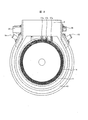
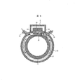
- FIG. 8 shows a simplified cross section of the present embodiment.
- the arrows indicate the flow of the cooling water.
- the cooling water entering from the inlet pipe 15 makes a U-turn as shown in FIG. 7 after passing under the heat radiating plate 42 of the power module 23 and between the fins 43. Therefore, in FIG. 8, this point (the right side of the flow path flat surface 38) goes in the direction toward the back of the page. Thereafter, the cooling water turns around the coil of the motor in a counterclockwise direction in this drawing and goes to the outlet pipe 16.
- the cooling water inlet pipe 15 is brought close to the vicinity of the power module 23 as much as possible, and consideration is given to cooling the power module 23 first by the coldest cooling water. By doing so, it is possible to minimize the thermal influence that the temperature of the coil 14 described above has on the power module 23.
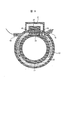
- FIG. 9 shows the shape of the inlet pipe 15 in FIG. 8 changed. Since the inlet pipe 15 is provided in parallel with the flat portion 38, the momentum of the cooling water when entering from the inlet pipe 15 becomes stronger than in the case of FIG. As a result, the power semiconductor element 5 is more effective in space-saving and efficient cooling.
- the inverter unit 2 and the motor unit 3 are completely integrated.
- the inverter unit 2 and the motor unit 3 can be made separately and integrated by combining them later. is there.
- An advantage of this is that if one of them breaks, only one of them needs to be repaired.
- a seal such as an O-ring is required on the divided surface.
- the temperature of the cooling water 44 here is not only the motor cooling water temperature but also the inverter cooling water. That is, although not shown in the drawing of the present embodiment, a temperature sensor is provided in the vicinity of the fin 43 in the cooling water 44 and the information is taken into the motor control board 20 to simultaneously manage the water temperature of the motor and the inverter. In other words, this is effective when temperature restriction is required for each part or when cooling is controlled. For example, when an adverse effect is likely to occur on the power module or the stator side of the motor due to an increase in the water temperature, it is possible to perform control such as restricting the current (limiting the torque) according to the water temperature.
Landscapes
- Engineering & Computer Science (AREA)
- Theoretical Computer Science (AREA)
- Physics & Mathematics (AREA)
- Power Engineering (AREA)
- Data Mining & Analysis (AREA)
- Databases & Information Systems (AREA)
- General Engineering & Computer Science (AREA)
- General Physics & Mathematics (AREA)
- Microelectronics & Electronic Packaging (AREA)
- Thermal Sciences (AREA)
- Motor Or Generator Cooling System (AREA)
- Inverter Devices (AREA)
Abstract
回転電機システムは、固定子と固定子に空隙を介して設けられた回転子とを有する回転電機と、固定子を保持する筺体と、筺体によって保持され、回転電機を駆動する電力変換装置と、固定子と電力変換装置との間の筺体部分に設けられ、固定子と電力変換装置とを冷却する冷媒が流される第一の冷却通路とを有し、電力変換装置はパワー半導体素子を収納するパワーモジュールを有し、パワーモジュールは放熱フィンを有し、放熱フィンはパワーモジュールと第一の冷却通路との間の開口部から冷媒側に突出している。
Description
本発明は、電力変換装置と一体化された回転電機(回転電機システム)の構造に関する。
現状の電気自動車,ハイブリッド自動車においては、回転電機と電力変換装置がそれぞれ別体にて搭載されるのが一般的である。車両内におけるそれらの搭載スペースや各コンポーネントにおける最適な冷却方法を考えると、それぞれが別体にして設置することが好都合であることが多い。ただし、部品点数の削減や回転電機と電力変換装置間のサージ対策を考えると、それらは一体であることが望ましい。
特許文献1ではインバータ一体型回転電機を開示しているが、冷却水タンクなどの構成を採用しているため装置全体が大型化してしまう課題がある。
本発明は、電力変換装置と一体化された回転電機(回転電機システム)において、性能を落とすことなく小型化する技術を提供する。
本発明の第1の態様によると、回転電機システムは、固定子と固定子に空隙を介して設けられた回転子とを有する回転電機と、固定子を保持する筺体と、筺体によって保持され、回転電機を駆動する電力変換装置と、固定子と電力変換装置との間の筺体部分に設けられ、固定子と電力変換装置とを冷却する冷媒が流される第一の冷却通路とを有し、電力変換装置は、パワー半導体素子を収納するパワーモジュールを有し、パワーモジュールは放熱フィンを有し、放熱フィンは、パワーモジュールと第一の冷却通路との間の開口部から冷媒側に突出している。
本発明の第2の態様によると、第1の態様の回転電機システムにおいて、固定子の外側の筐体部分に、回転電機の回転方向を周回するように設けられ、冷媒が流される第二の冷却通路とを有し、第二の冷却通路は、第一の冷却通路に対し、電力変換装置を冷却した後の冷媒が固定子を冷却するように連通するのが好ましい。
本発明の第3の態様によると、第2の態様の回転電機システムにおいて、第一の冷却通路は、冷媒が流れる方向を変える形状を有し、第二の冷却通路は、第一の冷却通路に対し、電力変換装置を冷却した後の冷媒が固定子を冷却するように連通するとともに、当該連通部分において、第一の冷却通路の断面積よりも第二の冷却通路の断面積の方が大きくなるように連通しているのが好ましい。
本発明の第4の態様によると、第1の態様の回転電機システムにおいて、パワーモジュールは、パワー半導体素子を二列に並べて収納し、第一の冷却通路において、冷媒は第一の列に並べられたパワー半導体素子を冷却した後に流れる方向を変えて、第二の列に並べられたパワー半導体素子を冷却するのが好ましい。
本発明の第5の態様によると、第1の態様の回転電機システムにおいて、放熱フィンの近傍に温度センサを有し、温度センサにより取得した温度データに基づいて冷却を制御するのが好ましい。
本発明の第6の態様によると、回転電機システムは、固定子と、固定子に回転空隙を介して回転するように設けられた回転子と、を有する回転電機と、固定子を保持する筺体によって保持され、回転電機を駆動する電力変換装置と、固定子と電力変換装置との間の筺体部分に設けられ、通路を流れる冷媒によって電力変換装置を冷却する第一の冷却通路と、固定子の外側の筺体部分に設けられ、通路を流れる冷媒が回転電機の回転方向を周回することによって固定子を冷却する第二の冷却通路と、を有し、第一の冷却通路は、冷媒が流れる方向を変える形状を有し、第二の冷却通路は、第一の冷却通路に対し、電力変換装置を冷却した後の冷媒が固定子を冷却するように連通するとともに、当該連通部分において、第一の冷却通路の断面積よりも第二の冷却通路の断面積の方が大きくなるよう連通している。
本発明の第7の態様によると、第6の態様の回転電機システムにおいて、電力変換装置は、パワー半導体素子を二列に並べて収納するパワーモジュールを有し、第一の冷却通路において、冷媒は第一の列に並べられたパワー半導体素子を冷却した後に流れる方向を変えて、第二の列に並べられたパワー半導体素子を冷却するのが好ましい。
本発明の第8の態様によると、第7の態様の回転電機システムにおいて、パワーモジュールの放熱板は放熱フィンを有し、放熱フィンは、パワーモジュールと第一の冷却通路との間の開口部から冷媒側に突出しているのが好ましい。
本発明の第9の態様によると、第8の態様の回転電機システムにおいて、放熱フィンの近傍に温度センサを有し、温度センサにより取得した温度データに基づいて冷却を制御するのが好ましい。
直接水冷方式をとる電力変換装置は、一般的な間接水冷に対して熱抵抗が低いため、パワー半導体素子の冷却に必要な面積が小さくてすむ。つまり回転電機と電力変換装置を一体化する際に、それらの水路を共有化し、電力変換装置を直接冷却方式で冷却することで小型な電力変換装置を備えた回転電機システムを実現することができる。
図1~図4は本発明の実施の形態の一つを示す。図5は本実施の形態の主回路を示しており、各主要部品が電気的にどのように接続されているかを表している。ここでは便宜上、電力変換装置をインバータ、回転電機をモータと称す。但し、回転電機はモータとしてだけではなく、発電機としても機能することができる。モータは、固定子と、この固定子に回転空隙を介して回転するように設けられた回転子(図示しない)とを有する。また、インバータは、固定子を保持する筺体によって保持され、モータを駆動するものである。
まず図5より、本実施の形態の電気的機能を説明する。波線で囲まれた部分が本実施の形態で説明するインバータ一体型モータ1に相当しており、これはおおまかにインバータ部2とモータ部3に分けられる。インバータ部2は、外部から接続されるバッテリ4からの電気的な入力(直流)を、パワー半導体素子5を規則的にスイッチングすることにより交流に変換し、モータ部3に送られる。ここで、図5の電気回路上は、モータ巻線のインピーダンス7で描かれており、インバータによって変換された交流はモータのインピーダンス8を通る。本実施の形態のパワー半導体素子5はIGBT(Insulated Gate Bipoler Transistor)を想定しているが、必要な周波数や電圧によって、他のパワー半導体素子(例えばMOS-FETなど)が選定される。ここでは、正極側(上アーム側)に3つのIGBT5aとフライホイールダイオード6a、負極側(下アーム側)に同じ数のIGBT5bとフライホイールダイオード6bを備えており、上下アーム一対で一つの相に対応している。
スイッチング時に発生する電圧の脈動(リップル)は、バッテリ4とパワー半導体素子5群の間に位置する平滑コンデンサ21により平滑される。
次に図1を説明する。この図1の上部にある直方体の部分がインバータ部2であり、その下部の筒状の部分がモータ部3である。本実施の形態では、インバータ部2とモータ部3は一つの金属製ハウジング(アウターハウジング10)を共有することで、一体化されている。つまり、アウターハウジング10の上段部がインバータ部2になっている。
インバータ部2の内部がインバータ室13になっており、この中にインバータ機能を実現するための部品が収納されている。図中は内部が見えるように省略しているが、実際にはインバータ部の最上部にはインバータ室13内部に異物や水分が混入しないようカバーを取り付けて使用する。
図1及び図2から分かるように、モータ部3のアウターハウジング10の内側には、別体になったインナーハウジング11があり、その内側にはモータのコイル14が備わっている。アウターハウジング10は、車両のエンジンまたはトランスミッションやギアボックスなどに取り付けられるようフランジ12を有している。図中は省略してあるが、フランジ12には任意に取付用のボルト穴が開けられる。
図1及び図3に示されているように、インバータ室13内には、上段からモータの制御を行うモータ制御基板20、電圧のリップルを平滑化する平滑コンデンサ21、モータ制御基板からの指令を受けてスイッチング素子のオン・オフを制御するゲートドライブ基板22、そしてインバータ部の最下部にはパワー半導体素子5を収納しているパワーモジュール23が重なるように配置される。本実施の形態のインバータでは放電抵抗25を備えており、インバータをオフした際に平滑コンデンサ21に溜まっていた電荷はこの放電抵抗25によって放電される。車両側との信号のやり取りのために、インバータ室13の外壁には信号コネクタ26が備わっており、その信号コネクタ26はインバータ室13の壁の内側でフラットケーブル27の一方と繋がっており、その他方はモータ制御基板20と接続されている。
外部にあるバッテリ4からの直流電力はインバータ部2の一端に配置された強電コネクタ28から入力される。その直流電力はパワーモジュール23の直流端子55に伝達され、パワーモジュール23により交流に変換され、パワーモジュール23の交流端子56から口出し線17を介してコイル14に伝達される。この時、交流の電流は、電流センサ24を通ってコイル14と接続されている。ここを通るAC電流は電流センサ24により検知され、その電流値はモータ制御基板20に伝達され、モータの制御に使われる。口出し線17とパワーモジュール23の接続ラインは、サージやノイズの影響を抑制するために極限まで短く設計されている。
図6にパワーモジュール23の縦構造の模式図、及び図10,図11にパワーモジュール23の外観詳細図を示す。パワーモジュール23の下部には、その内部のパワー半導体素子5がスイッチング時に発生する熱を逃がすための放熱板42が備わっており、その下面には放熱用のフィン43が配置されている。本実施の形態のフィン43は円柱状のピンフィンを複数配列しているが、フィン形状は他の形状でもかまわない。パワーモジュール23はインバータ室13の床面に開いた開口部35に蓋をするようにボルト57がボルト穴36と締結されることにより固定されるが、このとき、フィン43が開口部35から下方に突出する。
図7はインナーハウジング11のみを表している。この表面にある周方向に長い帯状の凹部が冷却流路37である。これはインナーハウジング上をほぼ帯状に一周するように延びている。インナーハウジング11がアウターハウジング10内に収まるときにアウターハウジング10が冷却流路37の蓋を形成することになる。このとき、入口パイプ15の下に流路入口部39が配置され、また、図中は省略しているが、冷却流路37の両側に並行してインナーハウジングを一周するようにOリングもしくは液状シールを入れることで、漏水防止対策が可能になる。
パワーモジュール23のフィン43は、開口部35から突出すると同時に、この冷却流路37の平坦面38の上に突出することになる。つまり本実施の形態では、パワー半導体素子5が発生する熱が放熱板42を介してその板と一体化されたフィン43に到達し、そのフィン43が直接冷却されることでパワー半導体素子が冷却される直接水冷方式を採ることになる。尚、ここでは冷却水による水冷を前提としているが、冷却媒体は水以外でもかまわない。
図6は直接水冷と間接水冷の比較のために、パワーモジュール23内部の縦構造を模式的に表したものである。(a)は直接水冷、(b)は間接水冷である。一般的なパワーモジュール23の内部縦構造は上から順に、パワー半導体素子5,絶縁基板45,放熱板42で構成されている。
間接水冷ではインバータケース46のケース内壁47の水路側にフィン43が備わっており、パワーモジュール23はそのケース内壁47のフィン43と対向する面に設置される。この時、パワーモジュールの放熱板42とインバータケースの内壁47の間には一般的に放熱グリース48が塗布されており、金属と金属が合わさる面においては熱伝導の向上に寄与している。つまり、パワー半導体素子5は、放熱板42から放熱グリース48とインバータケース内壁47を介して冷却水44に放熱している。
直接水冷では、パワーモジュール23が搭載される位置は間接水冷と同じようにインバータケース46に固定されるが、その搭載面には開口があり、パワーモジュールは放熱板42でこの開口部をふさぐように搭載される。つまり、放熱板42にフィン43がある場合にはフィン43がこの開口部から冷却水側に突出することとなり、冷却水44は直接的に放熱板42やフィン43に当ることでパワー半導体素子5の熱を引いている。
このとき、パワー半導体素子(IGBT)5から冷却水44までの熱抵抗は、間接水冷で約0.15℃/W、直接水冷で約0.09℃/W程度である。つまり、間接水冷では熱抵抗が1.5倍高い。これを放熱面積で考えると、直接水冷は間接水冷に比べ、パワーモジュール23の床面積がおおよそ1.5分の1で済むということになる。
モータのハウジング上にインバータを搭載する一体化形状においてインバータの床面積を減らすことは、インバータとモータを別体で使用する場合よりも重要であり、本実施の形態のような形態に直接水冷を適用することは効果的である。これは同時に、間接水冷を用いた場合に比べて体積当たりのトルクを増すことにもなる。
さらに、図10で示すように、本施例で用いるパワーモジュール23は6つのパワー半導体素子5が3つずつ対向するように配置されている(パワー半導体素子5を2列に並べて収納している)ため、水路の長手方向の長さを短くすることに寄与している。つまり、筒状のモータハウジング上に搭載するのに適したパワーモジュール形状になっている。
さらに、本実施の形態ではこのパワーモジュール23を冷却するために次のような工夫がされている。図7の冷却通路37は通常、入口から出口まで一方方向に流すことを想定されるが、本実施の形態では図7に示すように、パワーモジュール下部に相当する平坦部38でUターンするような形状で形成されている。この領域では水路幅が狭く、つまりパワーモジュール下部では流速が上げられ、内部の6つのパワー半導体素子5は省スペースで効率的に冷却される。
本実施の形態では、冷却通路37が2つの冷却通路(第一の冷却通路と第二の冷却通路)により構成される。第一の冷却通路は、固定子と電力変換装置との間の筺体部分に設けられ、通路を流れる冷媒によって電力変換装置を冷却するものである。このとき冷媒は第一の列に並べられたパワー半導体素子を冷却した後に流れる方向を変えて、第二の列に並べられた前記パワー半導体素子を冷却する。一方、第二の冷却通路は、固定子の外側の筺体部分に設けられ、通路を流れる冷媒が前記回転電機の回転方向を周回することによって固定子を冷却するものである。
上述したように、図7では第一の冷却通路は冷媒が平坦部38でUターンするような形状を有している。なお、図7では一例としてUターンさせる形状を示しているが、冷媒の流速が上がるように平坦部38で冷媒の流れの向きを変える形状であれば良い。
第二の冷却通路は、第一の冷却通路に対し、インバータを冷却した後の冷媒が固定子を冷却するように連通するとともに、当該連通部分において、第一の冷却通路の断面積よりも第二の冷却通路の断面積の方が大きくなるよう連通した構成を採用している。
本実施の形態の冷却水はインバータ部2を冷却すると同時に、モータの固定子コア及びコイル14の冷却も行うモータ冷却水としての役割も兼ねている。
ここで注意すべき点として、モータのコイル14の許容温度とパワーモジュール23の動作温度の差がある。一般にモータのコイル14は高温になりやすく、冷却水はアウターハウジング10,インナーハウジング11を一周する間に温度が上昇する。通常、コイル14温度は最大180℃付近まで到達することが予想され、その一方で、パワーモジュール23の動作温度は自己発熱による温度上昇分を含めて最大125℃~150℃付近が限界である。つまり、インバータとモータを一体化する際にはコイル14の温度がパワーモジュール23に与える影響を最小限に抑える設計が慣用となる。
図8は本実施の形態の断面を簡略的に示したものである。矢印は冷却水の流れを示しており、本図では入口パイプ15から入った冷却水はパワーモジュール23の放熱板42の下、及びフィン43の間を通過した後に図7のようにUターンするため、図8ではこの点(流路平坦面38右側)で紙面奥の方向に向かうことになる。その後冷却水は、本図面では反時計回りの方向にモータのコイル周辺を一周するように回り、出口パイプ16へ向かう。ここに示すように、本実施の形態では、冷却水の入口パイプ15をパワーモジュール23の近傍に極限まで近づけ、最も冷えている冷却水がまずパワーモジュール23を冷やすように配慮されている。こうすることで、先に述べたコイル14の温度がパワーモジュール23に与える熱的影響を最小限に抑えることが可能となる。
また、図9は、図8における入口パイプ15の形状を変更したものである。入口パイプ15が平坦部38と平行に設けられているため、入口パイプ15から入った時の冷却水の勢いが図8の場合よりも強くなり流速が上がる。その結果、パワー半導体素子5の省スペースで効率的な冷却に一層効果がある構成となる。
なお、本実施の形態においては、インバータ部2とモータ部3を完全に一体化した例を示したが、インバータ部2とモータ部3を別々に作り、後に合体することによる一体化も可能である。この利点として、仮にどちらか一方が壊れた場合に、片方のみの修復で済む等が挙げられるが、注意すべき点として、その分割面にはOリング等のシールが必要になる。
また、ここでの冷却水44の温度はモータ冷却水温度であると同時にインバータ冷却水でもある。つまり、本実施の形態の図中は示していないが、冷却水44内のフィン43近傍に温度センサを設けてその情報をモータ制御基板20に取り込むことで、モータとインバータの水温を同時に管理することになり、それぞれの部位に温度制限が必要な場合や冷却を制御する場合などに有効である。例えば、水温の上昇により、パワーモジュールやモータの固定子側に悪影響が出そうな場合は、水温に応じて電流を絞る(トルクに制限をかける)などの制御が可能となる。
上記では、種々の実施の形態および変形例を説明したが、本発明はこれらの内容に限定されるものではない。本発明の技術的思想の範囲内で考えられるその他の態様も本発明の範囲内に含まれる。
次の優先権基礎出願の開示内容は引用文としてここに組み込まれる。
日本国特許出願2010年第041233号(2010年2月26日出願)
日本国特許出願2010年第041233号(2010年2月26日出願)
Claims (9)
- 固定子と前記固定子に空隙を介して設けられた回転子とを有する回転電機と、
前記固定子を保持する筺体と、
前記筺体によって保持され、前記回転電機を駆動する電力変換装置と、
前記固定子と前記電力変換装置との間の筺体部分に設けられ、前記固定子と前記電力変換装置とを冷却する冷媒が流される第一の冷却通路と、
を有する回転電機システムであって、
前記電力変換装置は、パワー半導体素子を収納するパワーモジュールを有し、
前記パワーモジュールは、放熱フィンを有し、
前記放熱フィンは、前記パワーモジュールと前記第一の冷却通路との間の開口部から冷媒側に突出している回転電機システム。 - 請求項1に記載の回転電機システムにおいて、
前記固定子の外側の筐体部分に、前記回転電機の回転方向を周回するように設けられ、前記冷媒が流される第二の冷却通路とを有し、
前記第二の冷却通路は、前記第一の冷却通路に対し、前記電力変換装置を冷却した後の前記冷媒が前記固定子を冷却するように連通する回転電機システム。 - 請求項2に記載の回転電機システムにおいて、
前記第一の冷却通路は、前記冷媒が流れる方向を変える形状を有し、
前記第二の冷却通路は、前記第一の冷却通路に対し、前記電力変換装置を冷却した後の前記冷媒が前記固定子を冷却するように連通するとともに、当該連通部分において、前記第一の冷却通路の断面積よりも前記第二の冷却通路の断面積の方が大きくなるように連通している回転電機システム。 - 請求項1に記載の回転電機システムにおいて、
前記パワーモジュールは、パワー半導体素子を二列に並べて収納し、
前記第一の冷却通路において、前記冷媒は第一の列に並べられた前記パワー半導体素子を冷却した後に流れる方向を変えて、第二の列に並べられた前記パワー半導体素子を冷却する回転電機システム。 - 請求項1に記載の回転電機システムにおいて、
前記放熱フィンの近傍に温度センサを有し、
前記温度センサにより取得した温度データに基づいて冷却を制御する回転電機システム。 - 固定子と、前記固定子に回転空隙を介して回転するように設けられた回転子と、を有する回転電機と、
前記固定子を保持する筺体によって保持され、前記回転電機を駆動する電力変換装置と、
前記固定子と前記電力変換装置との間の筺体部分に設けられ、通路を流れる冷媒によって前記電力変換装置を冷却する第一の冷却通路と、
前記固定子の外側の筺体部分に設けられ、通路を流れる冷媒が前記回転電機の回転方向を周回することによって前記固定子を冷却する第二の冷却通路と、を有し、
前記第一の冷却通路は、前記冷媒が流れる方向を変える形状を有し、
前記第二の冷却通路は、前記第一の冷却通路に対し、前記電力変換装置を冷却した後の前記冷媒が前記固定子を冷却するように連通するとともに、当該連通部分において、前記第一の冷却通路の断面積よりも前記第二の冷却通路の断面積の方が大きくなるよう連通している、回転電機システム。 - 請求項6に記載の回転電機システムにおいて、
前記電力変換装置は、パワー半導体素子を二列に並べて収納するパワーモジュールを有し、
前記第一の冷却通路において、冷媒は第一の列に並べられた前記パワー半導体素子を冷却した後に流れる方向を変えて、第二の列に並べられた前記パワー半導体素子を冷却する回転電機システム。 - 請求項7に記載の回転電機システムにおいて、
前記パワーモジュールの放熱板は放熱フィンを有し、
前記放熱フィンは、前記パワーモジュールと前記第一の冷却通路との間の開口部から冷媒側に突出している回転電機システム。 - 請求項8に記載の回転電機システムにおいて、
前記放熱フィンの近傍に温度センサを有し、
前記温度センサにより取得した温度データに基づいて冷却を制御する回転電機システム。
Priority Applications (2)
| Application Number | Priority Date | Filing Date | Title |
|---|---|---|---|
| US13/580,263 US20130049495A1 (en) | 2010-02-26 | 2010-08-24 | Rotating electric machine system |
| US14/670,957 US9881019B2 (en) | 2010-02-26 | 2015-03-27 | Rotating electric machine system |
Applications Claiming Priority (2)
| Application Number | Priority Date | Filing Date | Title |
|---|---|---|---|
| JP2010041233A JP5492599B2 (ja) | 2010-02-26 | 2010-02-26 | 回転電機システム |
| JP2010-041233 | 2010-02-26 |
Related Child Applications (2)
| Application Number | Title | Priority Date | Filing Date |
|---|---|---|---|
| US13/580,263 A-371-Of-International US20130049495A1 (en) | 2010-02-26 | 2010-08-24 | Rotating electric machine system |
| US14/670,957 Continuation US9881019B2 (en) | 2010-02-26 | 2015-03-27 | Rotating electric machine system |
Publications (1)
| Publication Number | Publication Date |
|---|---|
| WO2011104909A1 true WO2011104909A1 (ja) | 2011-09-01 |
Family
ID=44506348
Family Applications (1)
| Application Number | Title | Priority Date | Filing Date |
|---|---|---|---|
| PCT/JP2010/064279 Ceased WO2011104909A1 (ja) | 2010-02-26 | 2010-08-24 | 回転電機システム |
Country Status (3)
| Country | Link |
|---|---|
| US (2) | US20130049495A1 (ja) |
| JP (1) | JP5492599B2 (ja) |
| WO (1) | WO2011104909A1 (ja) |
Cited By (8)
| Publication number | Priority date | Publication date | Assignee | Title |
|---|---|---|---|---|
| AT512123A1 (de) * | 2011-10-27 | 2013-05-15 | Avl List Gmbh | Elektrische maschine mit einer leistungselektronik |
| ITBO20120682A1 (it) * | 2012-12-18 | 2014-06-19 | Spal Automotive Srl | Macchina elettrica |
| CN106374680A (zh) * | 2015-07-24 | 2017-02-01 | 西门子公司 | 特别用于电动交通工具的电驱动单元 |
| CN110890813A (zh) * | 2018-09-06 | 2020-03-17 | 本田技研工业株式会社 | 驱动单元 |
| EP3306790B1 (en) * | 2015-05-26 | 2021-07-28 | Nissan Motor Co., Ltd. | Mechatronically integrated rotary electric machine |
| CN113316524A (zh) * | 2019-01-31 | 2021-08-27 | 日立安斯泰莫株式会社 | 轮驱动装置以及具备轮驱动装置的电动车辆 |
| WO2022033536A1 (en) * | 2020-08-12 | 2022-02-17 | Valeo Powertrain (shanghai) Co., Ltd. | An integrated drivetrain assembly for an electrified vehicle and an electrified vehicle |
| WO2025228591A1 (de) * | 2024-04-29 | 2025-11-06 | Sew-Eurodrive Gmbh & Co Kg | Antrieb, aufweisend einen elektromotor mit einem anschlusskasten |
Families Citing this family (109)
| Publication number | Priority date | Publication date | Assignee | Title |
|---|---|---|---|---|
| US12328346B2 (en) | 2010-09-13 | 2025-06-10 | Jeffrey W. Mankoff | Modifying signal associations in complex computing networks |
| DE102011080912A1 (de) * | 2011-08-12 | 2013-02-14 | Bayerische Motoren Werke Aktiengesellschaft | Fahrzeug mit Leistungselektronik |
| CN202222092U (zh) * | 2011-08-30 | 2012-05-16 | 中山大洋电机制造有限公司 | 一种电机控制器的igbt散热结构 |
| JP5836879B2 (ja) * | 2012-05-01 | 2015-12-24 | 日立オートモティブシステムズ株式会社 | インバータ装置 |
| CN110048548B (zh) * | 2012-09-21 | 2022-02-18 | 日产自动车株式会社 | 电动机的冷却构造 |
| KR102068178B1 (ko) * | 2012-12-03 | 2020-01-20 | 엘지전자 주식회사 | 전기자동차 |
| CN102983682B (zh) * | 2012-12-06 | 2015-02-04 | 青岛海西电机有限公司 | 隔爆型变频一体化永磁同步电动机 |
| JP5825310B2 (ja) * | 2013-09-05 | 2015-12-02 | 株式会社安川電機 | モータ駆動装置および車両 |
| JP5812066B2 (ja) * | 2013-09-05 | 2015-11-11 | 株式会社安川電機 | モータ駆動装置および車両 |
| DE102013217890A1 (de) * | 2013-09-06 | 2015-03-12 | Zf Friedrichshafen Ag | Elektromaschinengehäuse und Fahrzeugantrieb-Elektromaschine |
| WO2015036921A2 (en) * | 2013-09-10 | 2015-03-19 | Protean Electric Limited | Electric motor or generator |
| JP2015077032A (ja) * | 2013-10-11 | 2015-04-20 | 株式会社日立産機システム | 回転電機 |
| CN105745103B (zh) * | 2013-11-26 | 2019-08-23 | 舍弗勒技术股份两合公司 | 具有共同的冷却流的混合动力模块和功率电子器件模块 |
| DE102013021745A1 (de) * | 2013-12-20 | 2015-06-25 | Sew-Eurodrive Gmbh & Co Kg | Umrichtermotor |
| DE102013021740A1 (de) * | 2013-12-20 | 2015-06-25 | Sew-Eurodrive Gmbh & Co Kg | Umrichtermotor |
| EP2924852A1 (en) * | 2014-03-27 | 2015-09-30 | Skf Magnetic Mechatronics | High speed electrical machine with embedded drive |
| KR101518965B1 (ko) * | 2014-05-15 | 2015-05-11 | (주)엑스엠더블유 | 방열 특성을 향상시킨 소형화된 주파수 상향 변환기 |
| CN106068601B (zh) * | 2014-05-26 | 2018-09-28 | 株式会社日立产机系统 | 旋转电机装配体 |
| JP5904235B2 (ja) * | 2014-05-30 | 2016-04-13 | トヨタ自動車株式会社 | 電動車両用の電力変換器 |
| JP6442922B2 (ja) * | 2014-08-22 | 2018-12-26 | 日本電産株式会社 | モータ |
| JP2016073058A (ja) * | 2014-09-29 | 2016-05-09 | 株式会社神戸製鋼所 | インバータ一体型電動機 |
| RU2637805C1 (ru) * | 2014-09-30 | 2017-12-07 | Ниссан Мотор Ко., Лтд. | Система вращающейся электрической машины |
| CN104319950B (zh) * | 2014-10-30 | 2017-01-25 | 兖州东方机电有限公司 | 一种变频调速一体机 |
| JP6838853B2 (ja) * | 2014-11-14 | 2021-03-03 | 日産自動車株式会社 | 回転電機システム |
| JP6327174B2 (ja) * | 2015-02-20 | 2018-05-23 | 株式会社安川電機 | 駆動装置 |
| JP6421637B2 (ja) * | 2015-02-23 | 2018-11-14 | 株式会社明電舎 | インバータシステム |
| JP6582468B2 (ja) * | 2015-03-18 | 2019-10-02 | 日産自動車株式会社 | 回転電機構造 |
| US20180298914A1 (en) * | 2015-04-28 | 2018-10-18 | Denso Corporation | Blower |
| MY167716A (en) * | 2015-05-20 | 2018-09-21 | Nissan Motor | Drive device |
| JP6769707B2 (ja) | 2015-12-03 | 2020-10-14 | ローム株式会社 | 半導体モジュール |
| US10038351B2 (en) | 2016-03-17 | 2018-07-31 | Ford Global Technologies, Llc | Thermal management assembly for an electrified vehicle |
| US10536055B2 (en) | 2016-03-17 | 2020-01-14 | Ford Global Technologies, Llc | Thermal management assembly for an electrified vehicle |
| US10008908B2 (en) | 2016-03-17 | 2018-06-26 | Ford Global Technologies, Llc | Electric machine for vehicle |
| US10086538B2 (en) * | 2016-03-17 | 2018-10-02 | Ford Global Technologies, Llc | Thermal management assembly for an electrified vehicle |
| GB2549086B (en) | 2016-03-30 | 2022-09-07 | Advanced Electric Machines Group Ltd | Electrical sub-assembly |
| KR101836259B1 (ko) * | 2016-04-18 | 2018-03-08 | 현대자동차 주식회사 | 구동모터의 냉각유닛 |
| WO2017212556A1 (ja) * | 2016-06-07 | 2017-12-14 | 三菱電機株式会社 | 回転電機冷却装置 |
| CN106712368A (zh) * | 2016-12-14 | 2017-05-24 | 合普动力股份有限公司 | 电动汽车用一体化电机控制器水冷机壳 |
| CN106533035A (zh) * | 2016-12-30 | 2017-03-22 | 合普动力股份有限公司 | 电动汽车用一体化电机控制器 |
| DE102017103197A1 (de) | 2017-02-16 | 2018-08-16 | Schaeffler Technologies AG & Co. KG | Elektronikgehäuse für einen E-Achsen-Antrieb und E-Achse mit Elektronikgehäuse |
| FR3064840B1 (fr) * | 2017-04-03 | 2019-12-27 | Mmt ag | Machine electrique haute puissance thermoregulee |
| CN110771025A (zh) | 2017-05-08 | 2020-02-07 | 日产自动车株式会社 | 电力变换装置的冷却构造 |
| FI130033B (en) * | 2017-05-24 | 2022-12-30 | Aurora Powertrains Oy | Snowmobile with electric motor and manufacturing method for a snowmobile with electric motor |
| JP2020162185A (ja) * | 2017-07-28 | 2020-10-01 | 日本電産トーソク株式会社 | モータ |
| JP2020162186A (ja) * | 2017-07-28 | 2020-10-01 | 日本電産トーソク株式会社 | モータ |
| US11552536B2 (en) | 2017-09-18 | 2023-01-10 | Robert Bosch Gmbh | Electric motor and inverter assembly |
| FR3071978B1 (fr) * | 2017-09-29 | 2020-06-19 | Valeo Equipements Electriques Moteur | Circuit de refroidissement avec liquide pour machine electrique tournante |
| CN107659059A (zh) * | 2017-10-16 | 2018-02-02 | 浙江零跑科技有限公司 | 一种电机和电控的一体化结构 |
| JP6628779B2 (ja) | 2017-10-25 | 2020-01-15 | 本田技研工業株式会社 | 機電一体型回転電機装置 |
| JP2019118244A (ja) * | 2017-12-27 | 2019-07-18 | 日本電産トーソク株式会社 | モータ |
| DE102018203369A1 (de) | 2018-03-07 | 2019-09-12 | Robert Bosch Gmbh | Gehäuseelement, Anordnung von elektrischen Komponenten auf einem Gehäuseelement und elektrische Maschine |
| CN108258838A (zh) * | 2018-03-22 | 2018-07-06 | 合肥巨动力系统有限公司 | 一种电机系统一体化结构 |
| KR102029846B1 (ko) * | 2018-05-16 | 2019-10-08 | 현대자동차 주식회사 | 구동모터 및 감속기 일체형의 구동 시스템 |
| JP6977682B2 (ja) | 2018-07-25 | 2021-12-08 | 株式会社デンソー | 回転電機ユニット |
| CN110784068A (zh) * | 2018-07-27 | 2020-02-11 | 台达电子工业股份有限公司 | 水冷式马达驱动器一体机 |
| US11283330B2 (en) * | 2018-07-27 | 2022-03-22 | Delta Electronics, Inc. | Integrated apparatus of water-cooled motor and driver |
| EP3627667B1 (en) * | 2018-09-18 | 2025-09-03 | KNORR-BREMSE Systeme für Nutzfahrzeuge GmbH | Wheel brake actuator and method of controlling a cooling system of an electric motor |
| JP2020089170A (ja) * | 2018-11-29 | 2020-06-04 | 株式会社デンソー | 電駆動モジュール |
| JP7241096B2 (ja) * | 2019-01-10 | 2023-03-16 | 三菱重工エンジン&ターボチャージャ株式会社 | モータ、及びインバータ一体型回転電機 |
| DE112020000433T5 (de) | 2019-01-16 | 2021-09-30 | Borgwarner Inc. | Integriertes Statorkühlmantelsystem |
| US12368332B2 (en) * | 2019-01-16 | 2025-07-22 | Borgwarner Inc. | Integrated stator cooling jacket system |
| WO2020166150A1 (ja) | 2019-02-12 | 2020-08-20 | アイシン・エィ・ダブリュ株式会社 | インバータユニット |
| BE1027048B1 (nl) * | 2019-02-12 | 2020-09-10 | Punch Powertrain Nv | Elektrische aandrijfeenheid en werkwijze voor de vervaardiging daarvan |
| US11031846B2 (en) * | 2019-03-08 | 2021-06-08 | Abb Schweiz Ag | Co-packaged electric motor and motor drive |
| CN113826309B (zh) * | 2019-03-20 | 2024-05-10 | Lg麦格纳电子动力总成有限公司 | 智能型动力生成模块 |
| EP4625781A3 (en) | 2019-04-25 | 2026-02-25 | American Axle & Manufacturing, Inc. | Electric drive module |
| DE102019111594A1 (de) * | 2019-05-06 | 2020-11-12 | Bayerische Motoren Werke Aktiengesellschaft | Antriebsanordnung für ein Fahrzeug mit einer elektrischen Maschine und einer Wechselrichtervorrichtung sowie Herstellungsverfahren |
| WO2021002330A1 (ja) * | 2019-07-02 | 2021-01-07 | 本田技研工業株式会社 | 駆動ユニット及び車両 |
| CN112186951A (zh) * | 2019-07-04 | 2021-01-05 | 中车株洲电力机车研究所有限公司 | 一种电机组件 |
| US10780849B1 (en) * | 2019-08-07 | 2020-09-22 | GM Global Technology Operations LLC | Electric drive units with integrated power electronics for vehicle powertrains |
| CN112387937B (zh) * | 2019-08-12 | 2022-07-12 | 中车株洲电力机车研究所有限公司 | 永磁同步电机、电机壳体及用于加工的砂芯 |
| JP7208124B2 (ja) * | 2019-09-20 | 2023-01-18 | 日立Astemo株式会社 | 電力変換装置およびモータ一体型電力変換装置 |
| WO2021065299A1 (ja) * | 2019-09-30 | 2021-04-08 | 日本電産株式会社 | モータユニット |
| WO2021065452A1 (ja) * | 2019-09-30 | 2021-04-08 | 日本電産株式会社 | モータユニット |
| JP2021061675A (ja) * | 2019-10-04 | 2021-04-15 | 日本電産株式会社 | モータユニット |
| WO2021086694A1 (en) * | 2019-11-02 | 2021-05-06 | Borgwarner Inc. | Drive module with improved efficiency |
| WO2021089188A1 (en) | 2019-11-06 | 2021-05-14 | Eaton Intelligent Power Limited | Axial flux motor with cooling jacket |
| US12266985B2 (en) | 2019-12-10 | 2025-04-01 | Eaton Intelligent Power Limited | Axial flux motor with cooling jacket |
| DE102020214816A1 (de) | 2019-12-30 | 2021-07-01 | Robert Bosch Gesellschaft mit beschränkter Haftung | Elektronikvorrichtung und Werkzeugmaschine mit der Elektronikvorrichtung |
| US12424897B2 (en) | 2020-02-21 | 2025-09-23 | Eaton Intelligent Power Limited | Electric motor with integrated cooling system |
| JP2021146480A (ja) * | 2020-03-23 | 2021-09-27 | 川崎重工業株式会社 | 冷却装置、ロボット、及び冷却装置のロボットへの取り付け方法 |
| JP2021146481A (ja) * | 2020-03-23 | 2021-09-27 | 川崎重工業株式会社 | ロボット及び冷却装置のロボットへの取り付け方法 |
| JP7506501B2 (ja) * | 2020-03-23 | 2024-06-26 | 川崎重工業株式会社 | 冷却装置、ロボット、及び冷却装置のロボットへの取り付け方法 |
| FR3113446B1 (fr) * | 2020-08-12 | 2023-09-08 | Thermodyn | Système comprenant un dispositif de refroidissement pour une machine enfermée dans un carter sous pression |
| US11230288B1 (en) | 2020-09-28 | 2022-01-25 | GM Global Technology Operations LLC | Optimized regenerative braking for hybrid electric vehicle (HEV) powertrain configurations |
| US12542471B2 (en) | 2020-11-04 | 2026-02-03 | Hitachi Astemo, Ltd. | Inverter integrated motor |
| CN114583884A (zh) * | 2020-12-02 | 2022-06-03 | 法雷奥动力系统(南京)有限公司 | 用于电动车的动力总成系统和电动车 |
| EP4027494B1 (en) | 2021-01-08 | 2023-11-08 | Taiga Motors Inc. | Drive unit for electric vehicle |
| JP7509048B2 (ja) * | 2021-02-02 | 2024-07-02 | トヨタ自動車株式会社 | 電動車両 |
| EP4040651A1 (en) * | 2021-02-08 | 2022-08-10 | Hamilton Sundstrand Corporation | Motor and motor drive arrangement |
| CN113374657B (zh) * | 2021-05-28 | 2023-02-17 | 天津明智润阳技术有限公司 | 一种液相介质降温设备及其控制方法 |
| JP2023015883A (ja) * | 2021-07-20 | 2023-02-01 | 日産自動車株式会社 | モータ用ハウジング |
| KR102909377B1 (ko) * | 2021-08-09 | 2026-01-07 | 현대자동차 주식회사 | 모터 일체형 인버터 장치 |
| US12088149B2 (en) | 2021-12-02 | 2024-09-10 | Borgwarner Inc. | Cooling system for an electric machine |
| JP7781914B2 (ja) * | 2021-12-28 | 2025-12-08 | Astemo株式会社 | 電動駆動装置 |
| JP7331961B2 (ja) * | 2022-01-05 | 2023-08-23 | 株式会社明電舎 | 回転機 |
| JP7371705B2 (ja) * | 2022-01-05 | 2023-10-31 | 株式会社明電舎 | 回転機 |
| US11942825B2 (en) | 2022-01-12 | 2024-03-26 | Dana Automotive Systems Group, Llc | Cooling system for an electric machine |
| WO2023225517A1 (en) * | 2022-05-16 | 2023-11-23 | Hydro-Gear Limited Partnership | Liquid-cooled electric drive assembly |
| JP7655274B2 (ja) * | 2022-05-25 | 2025-04-02 | トヨタ自動車株式会社 | 機電一体ユニット |
| US12323025B2 (en) * | 2022-10-24 | 2025-06-03 | Schaeffler Technologies AG & Co. KG | Heat exchanger system for an electric motor with fluid circuits arranged between shafts |
| EP4366140A1 (en) * | 2022-11-07 | 2024-05-08 | Valeo eAutomotive Germany GmbH | A compact electric drive with a structure allowing efficient heat dissipation |
| JP2024122694A (ja) * | 2023-02-28 | 2024-09-09 | トヨタ自動車株式会社 | 電動車両 |
| DE102023108953A1 (de) | 2023-04-06 | 2024-10-10 | Rolls-Royce Deutschland Ltd & Co Kg | Stromrichtermodul für eine rotierende elektrische Maschine |
| JP7796692B2 (ja) * | 2023-04-25 | 2026-01-09 | 本田技研工業株式会社 | 電動機の冷却装置 |
| US12706504B2 (en) * | 2023-12-08 | 2026-08-11 | Garrett Transportation I Inc. | E-machine system with multi-function support bracket for electrical component |
| GB2636840A (en) | 2023-12-22 | 2025-07-02 | Evolito Ltd | An electric propulsion unit |
| EP4593261A1 (en) * | 2024-01-29 | 2025-07-30 | BRP-Rotax GmbH & Co. KG | Electric power unit |
| DE102024136781A1 (de) * | 2024-12-09 | 2026-06-11 | Valeo Eautomotive Germany Gmbh | Elektrische Maschine mit einem mittels Wechselrichter verschlossenen Maschinengehäuse |
Citations (3)
| Publication number | Priority date | Publication date | Assignee | Title |
|---|---|---|---|---|
| JP2002314281A (ja) * | 2001-04-16 | 2002-10-25 | Hitachi Ltd | 冷却水路を備えた電気装置 |
| JP2003101277A (ja) * | 2001-09-26 | 2003-04-04 | Toyota Motor Corp | 発熱素子冷却用構造体及びその製造方法 |
| JP2008253041A (ja) * | 2007-03-30 | 2008-10-16 | Toyota Motor Corp | モータ駆動装置 |
Family Cites Families (11)
| Publication number | Priority date | Publication date | Assignee | Title |
|---|---|---|---|---|
| US4739204A (en) * | 1986-01-30 | 1988-04-19 | Mitsubishi Denki Kabushiki Kaisha | Liquid cooled a.c. vehicle generator |
| US4980588A (en) * | 1986-02-14 | 1990-12-25 | Mitsubishi Denki Kabushiki Kaisha | Water-cooled vehicle generator |
| JPS62260544A (ja) * | 1986-04-07 | 1987-11-12 | Mitsubishi Electric Corp | 車両用交流発電機 |
| EP0816147A3 (en) * | 1996-07-02 | 2000-03-08 | Denso Corporation | Rotating apparatus and heating apparatus, for vehicle |
| JP3877894B2 (ja) * | 1999-01-13 | 2007-02-07 | 三菱電機株式会社 | 車両用ブラシレス交流発電機 |
| US6414867B2 (en) * | 2000-02-16 | 2002-07-02 | Hitachi, Ltd. | Power inverter |
| GB2388404B (en) * | 2002-05-09 | 2005-06-01 | Dana Automotive Ltd | Electric pump |
| JP4327618B2 (ja) | 2004-02-05 | 2009-09-09 | トヨタ自動車株式会社 | インバータ一体型回転電機およびその回転電機を備えた車両 |
| US7923875B2 (en) * | 2008-04-25 | 2011-04-12 | A.O. Smith Corporation | Assembly for an electric machine |
| JP5184218B2 (ja) * | 2008-06-02 | 2013-04-17 | 本田技研工業株式会社 | コンデンサ搭載型インバータユニット |
| JP4657329B2 (ja) * | 2008-07-29 | 2011-03-23 | 日立オートモティブシステムズ株式会社 | 電力変換装置および電動車両 |
-
2010
- 2010-02-26 JP JP2010041233A patent/JP5492599B2/ja active Active
- 2010-08-24 WO PCT/JP2010/064279 patent/WO2011104909A1/ja not_active Ceased
- 2010-08-24 US US13/580,263 patent/US20130049495A1/en not_active Abandoned
-
2015
- 2015-03-27 US US14/670,957 patent/US9881019B2/en active Active
Patent Citations (3)
| Publication number | Priority date | Publication date | Assignee | Title |
|---|---|---|---|---|
| JP2002314281A (ja) * | 2001-04-16 | 2002-10-25 | Hitachi Ltd | 冷却水路を備えた電気装置 |
| JP2003101277A (ja) * | 2001-09-26 | 2003-04-04 | Toyota Motor Corp | 発熱素子冷却用構造体及びその製造方法 |
| JP2008253041A (ja) * | 2007-03-30 | 2008-10-16 | Toyota Motor Corp | モータ駆動装置 |
Cited By (14)
| Publication number | Priority date | Publication date | Assignee | Title |
|---|---|---|---|---|
| AT13238U1 (de) * | 2011-10-27 | 2013-09-15 | Avl List Gmbh | Elektrische Maschine mit einer Leistungselektronik |
| AT512123A1 (de) * | 2011-10-27 | 2013-05-15 | Avl List Gmbh | Elektrische maschine mit einer leistungselektronik |
| ITBO20120682A1 (it) * | 2012-12-18 | 2014-06-19 | Spal Automotive Srl | Macchina elettrica |
| WO2014097109A1 (en) * | 2012-12-18 | 2014-06-26 | Spal Automotive S.R.L. | Electrical machine. |
| US9997971B2 (en) | 2012-12-18 | 2018-06-12 | Spal Automotive S.R.L. | Electrical machine |
| EP3306790B1 (en) * | 2015-05-26 | 2021-07-28 | Nissan Motor Co., Ltd. | Mechatronically integrated rotary electric machine |
| CN106374680A (zh) * | 2015-07-24 | 2017-02-01 | 西门子公司 | 特别用于电动交通工具的电驱动单元 |
| CN110890813A (zh) * | 2018-09-06 | 2020-03-17 | 本田技研工业株式会社 | 驱动单元 |
| CN113316524A (zh) * | 2019-01-31 | 2021-08-27 | 日立安斯泰莫株式会社 | 轮驱动装置以及具备轮驱动装置的电动车辆 |
| CN113316524B (zh) * | 2019-01-31 | 2024-05-10 | 日立安斯泰莫株式会社 | 轮驱动装置以及具备轮驱动装置的电动车辆 |
| WO2022033536A1 (en) * | 2020-08-12 | 2022-02-17 | Valeo Powertrain (shanghai) Co., Ltd. | An integrated drivetrain assembly for an electrified vehicle and an electrified vehicle |
| CN114079354A (zh) * | 2020-08-12 | 2022-02-22 | 法雷奥动力总成(上海)有限公司 | 用于电动车的动力总成系统和电动车 |
| JP2023537137A (ja) * | 2020-08-12 | 2023-08-30 | ヴァレオ、パワートレイン、(ナンジン)、カンパニー、リミテッド | 電動化車両用の統合型ドライブトレイン組立体および電動化車両 |
| WO2025228591A1 (de) * | 2024-04-29 | 2025-11-06 | Sew-Eurodrive Gmbh & Co Kg | Antrieb, aufweisend einen elektromotor mit einem anschlusskasten |
Also Published As
| Publication number | Publication date |
|---|---|
| JP5492599B2 (ja) | 2014-05-14 |
| US20150199376A1 (en) | 2015-07-16 |
| JP2011182480A (ja) | 2011-09-15 |
| US9881019B2 (en) | 2018-01-30 |
| US20130049495A1 (en) | 2013-02-28 |
Similar Documents
| Publication | Publication Date | Title |
|---|---|---|
| JP5492599B2 (ja) | 回転電機システム | |
| KR100689940B1 (ko) | 구동 장치 | |
| CN103339839B (zh) | 电力控制装置的搭载结构 | |
| JP5323039B2 (ja) | 電力変換装置 | |
| JP4644275B2 (ja) | 電力変換装置および電動車両 | |
| RU2637805C1 (ru) | Система вращающейся электрической машины | |
| JP5501257B2 (ja) | 回転電機ユニット | |
| JP4909712B2 (ja) | 電力変換装置 | |
| US9231446B2 (en) | Motor drive device and vehicle | |
| JP5962752B2 (ja) | 電力変換装置 | |
| CN109311376B (zh) | 用于车辆的电气轴驱动器 | |
| JP6621491B2 (ja) | 回転電機 | |
| JP6854936B1 (ja) | 回転電機 | |
| JP2012170177A (ja) | 電力制御装置の搭載構造 | |
| WO2012120672A1 (ja) | 冷却器 | |
| JP6180857B2 (ja) | 電力変換装置 | |
| CN111884527A (zh) | 电力转换装置 | |
| US20200068749A1 (en) | Cooling structure of power conversion device | |
| JP2020114087A (ja) | 車載用冷却装置 | |
| CN114157098A (zh) | 旋转电机 | |
| JP5252052B2 (ja) | 油圧ユニット | |
| JP5268880B2 (ja) | 電力変換装置 | |
| CN112385123A (zh) | 旋转电机 | |
| JP2019161019A (ja) | 電力変換装置 |
Legal Events
| Date | Code | Title | Description |
|---|---|---|---|
| 121 | Ep: the epo has been informed by wipo that ep was designated in this application |
Ref document number: 10846572 Country of ref document: EP Kind code of ref document: A1 |
|
| NENP | Non-entry into the national phase |
Ref country code: DE |
|
| WWE | Wipo information: entry into national phase |
Ref document number: 13580263 Country of ref document: US |
|
| 122 | Ep: pct application non-entry in european phase |
Ref document number: 10846572 Country of ref document: EP Kind code of ref document: A1 |