WO2011102372A1 - ボールジョイント装置 - Google Patents
ボールジョイント装置 Download PDFInfo
- Publication number
- WO2011102372A1 WO2011102372A1 PCT/JP2011/053255 JP2011053255W WO2011102372A1 WO 2011102372 A1 WO2011102372 A1 WO 2011102372A1 JP 2011053255 W JP2011053255 W JP 2011053255W WO 2011102372 A1 WO2011102372 A1 WO 2011102372A1
- Authority
- WO
- WIPO (PCT)
- Prior art keywords
- peripheral surface
- ball
- joint device
- ball joint
- ball seat
- Prior art date
- Legal status (The legal status is an assumption and is not a legal conclusion. Google has not performed a legal analysis and makes no representation as to the accuracy of the status listed.)
- Ceased
Links
Images






Classifications
-
- F—MECHANICAL ENGINEERING; LIGHTING; HEATING; WEAPONS; BLASTING
- F16—ENGINEERING ELEMENTS AND UNITS; GENERAL MEASURES FOR PRODUCING AND MAINTAINING EFFECTIVE FUNCTIONING OF MACHINES OR INSTALLATIONS; THERMAL INSULATION IN GENERAL
- F16C—SHAFTS; FLEXIBLE SHAFTS; ELEMENTS OR CRANKSHAFT MECHANISMS; ROTARY BODIES OTHER THAN GEARING ELEMENTS; BEARINGS
- F16C11/00—Pivots; Pivotal connections
- F16C11/04—Pivotal connections
- F16C11/06—Ball-joints; Other joints having more than one degree of angular freedom, i.e. universal joints
- F16C11/0619—Ball-joints; Other joints having more than one degree of angular freedom, i.e. universal joints the female part comprising a blind socket receiving the male part
- F16C11/0623—Construction or details of the socket member
- F16C11/0628—Construction or details of the socket member with linings
- F16C11/0633—Construction or details of the socket member with linings the linings being made of plastics
-
- F—MECHANICAL ENGINEERING; LIGHTING; HEATING; WEAPONS; BLASTING
- F16—ENGINEERING ELEMENTS AND UNITS; GENERAL MEASURES FOR PRODUCING AND MAINTAINING EFFECTIVE FUNCTIONING OF MACHINES OR INSTALLATIONS; THERMAL INSULATION IN GENERAL
- F16C—SHAFTS; FLEXIBLE SHAFTS; ELEMENTS OR CRANKSHAFT MECHANISMS; ROTARY BODIES OTHER THAN GEARING ELEMENTS; BEARINGS
- F16C11/00—Pivots; Pivotal connections
- F16C11/04—Pivotal connections
- F16C11/06—Ball-joints; Other joints having more than one degree of angular freedom, i.e. universal joints
- F16C11/0685—Manufacture of ball-joints and parts thereof, e.g. assembly of ball-joints
-
- Y—GENERAL TAGGING OF NEW TECHNOLOGICAL DEVELOPMENTS; GENERAL TAGGING OF CROSS-SECTIONAL TECHNOLOGIES SPANNING OVER SEVERAL SECTIONS OF THE IPC; TECHNICAL SUBJECTS COVERED BY FORMER USPC CROSS-REFERENCE ART COLLECTIONS [XRACs] AND DIGESTS
- Y10—TECHNICAL SUBJECTS COVERED BY FORMER USPC
- Y10T—TECHNICAL SUBJECTS COVERED BY FORMER US CLASSIFICATION
- Y10T403/00—Joints and connections
- Y10T403/32—Articulated members
- Y10T403/32606—Pivoted
- Y10T403/32631—Universal ball and socket
-
- Y—GENERAL TAGGING OF NEW TECHNOLOGICAL DEVELOPMENTS; GENERAL TAGGING OF CROSS-SECTIONAL TECHNOLOGIES SPANNING OVER SEVERAL SECTIONS OF THE IPC; TECHNICAL SUBJECTS COVERED BY FORMER USPC CROSS-REFERENCE ART COLLECTIONS [XRACs] AND DIGESTS
- Y10—TECHNICAL SUBJECTS COVERED BY FORMER USPC
- Y10T—TECHNICAL SUBJECTS COVERED BY FORMER US CLASSIFICATION
- Y10T403/00—Joints and connections
- Y10T403/32—Articulated members
- Y10T403/32606—Pivoted
- Y10T403/32631—Universal ball and socket
- Y10T403/32713—Elastomerically biased or backed components
-
- Y—GENERAL TAGGING OF NEW TECHNOLOGICAL DEVELOPMENTS; GENERAL TAGGING OF CROSS-SECTIONAL TECHNOLOGIES SPANNING OVER SEVERAL SECTIONS OF THE IPC; TECHNICAL SUBJECTS COVERED BY FORMER USPC CROSS-REFERENCE ART COLLECTIONS [XRACs] AND DIGESTS
- Y10—TECHNICAL SUBJECTS COVERED BY FORMER USPC
- Y10T—TECHNICAL SUBJECTS COVERED BY FORMER US CLASSIFICATION
- Y10T403/00—Joints and connections
- Y10T403/32—Articulated members
- Y10T403/32606—Pivoted
- Y10T403/32631—Universal ball and socket
- Y10T403/32721—Elastomeric seat
-
- Y—GENERAL TAGGING OF NEW TECHNOLOGICAL DEVELOPMENTS; GENERAL TAGGING OF CROSS-SECTIONAL TECHNOLOGIES SPANNING OVER SEVERAL SECTIONS OF THE IPC; TECHNICAL SUBJECTS COVERED BY FORMER USPC CROSS-REFERENCE ART COLLECTIONS [XRACs] AND DIGESTS
- Y10—TECHNICAL SUBJECTS COVERED BY FORMER USPC
- Y10T—TECHNICAL SUBJECTS COVERED BY FORMER US CLASSIFICATION
- Y10T403/00—Joints and connections
- Y10T403/32—Articulated members
- Y10T403/32606—Pivoted
- Y10T403/32631—Universal ball and socket
- Y10T403/32737—Universal ball and socket including liner, shim, or discrete seat
Definitions
- the present invention relates to a ball joint device used for a mechanism element connection portion of various machines, and more particularly to a technique capable of reducing rocking and sliding torque and elastic lift.
- the vehicle stabilizer has a function of connecting the stabilizer bar to the suspension device of the vehicle and stabilizing the posture of the vehicle using the torsional reaction force of the stabilizer bar.
- a stabilizer for a vehicle is configured so that both ends of a U-shaped stabilizer bar are connected to the operating part of the suspension device, and the torsion part of the stabilizer bar is fixed to the vehicle body frame with a fixing member to receive a torsional reaction force. Has been.
- a ball joint device that connects the stabilizer and the struts and arms is used (see, for example, Japanese Patent No. 3168229 and Japanese Patent No. 3369659).
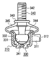
- FIG. 7 is a cross-sectional view showing an example of a ball joint device.
- the ball joint device 310 includes a rod member 311 and a housing 312 that is integrally provided at the end of the rod member 311. Bending edges 314 are provided on the left and right sides of the rod member 311.
- the housing 312 has a ball sheet insertion portion 320 drawn into a cylindrical shape, and a bottom surface 321 positioned at the end of the ball sheet insertion portion 320.
- a flange portion 323 is provided at the opening of the ball seat insertion portion 320.
- a plurality of holes 324 are punched out on the bottom surface 321.
- the ball sheet 330 is accommodated in the ball sheet insertion portion 320.
- the ball sheet 330 is made of a thermoplastic synthetic resin and has a concave spherical surface 331 and an outer peripheral surface 332.
- the spherical head 341 of the stud ball 340 is rotatably fitted to the concave spherical surface 331 of the ball seat 330.
- the stud ball 340 includes a screw portion 342 and a large diameter portion 343, and a dust cover 345 is provided between the flange portion 344 and the large diameter portion 343 of the ball sheet 330.
- the stud ball 340 and the ball seat 330 are rocked and slid as the suspension of the vehicle strokes.
- the characteristic at the time of rocking / sliding is defined as rocking / sliding torque or rocking torque and rotational torque.
- the inner diameter of the inner peripheral surface of the housing 312 is formed smaller than the outer diameter of the outer peripheral surface of the ball sheet 330 so that the ball sheet 330 is sufficiently fixed in the housing 312 by elastic force.
- the difference between the inner diameter of the inner peripheral surface of the housing 312 and the outer diameter of the outer peripheral surface of the ball seat 330 is referred to as a fastening allowance.
- the ball joint device using the above-described low torque type ball seat has the following problems.
- the ball sheet is a resin part manufactured by injection molding
- the outer diameter of the outer peripheral surface of the ball sheet is not constant due to the effect of thermal shrinkage during molding, and the taper shape expands toward the opening side. ing.
- the inner peripheral surface of the recess of the housing has a straight shape (constant inner diameter) as shown in FIG.
- FIG. 9 is an explanatory diagram showing the relationship between the inner diameter (R) of the inner peripheral surface of the housing and the outer diameter of the outer peripheral surface of the ball seat.
- the conventional ball seat (Qa) has a sufficient tightening margin, a region where the ball seat and the housing are in close contact with each other is widened, and the support is stabilized.
- the low torque type ball seat (Qb) with a small tightening margin, there is a portion where the gap generated between the ball seat and the housing becomes excessive (elastic lift), and the contact between the stud ball and the ball seat Becomes local (X). This occurs as looseness and may cause unpleasant noise and vibration.
- the elastic lift is a deflection when a load is applied.
- 10 and 11 are explanatory views showing the relationship between the load and the deflection before and after the test in comparison with the case of a normal ball seat and a low torque type ball seat when the endurance test of the ball joint device is performed. .
- the inner peripheral surface of the housing is constant, the amount of elastic lift increases when the tightening margin is lowered using a low torque type ball seat, and after the test, the ball seat is deformed and rattling occurs.
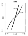
- FIG. 12 is an explanatory diagram showing the relationship between the tightening allowance between the ball seat and the housing incorporated in the ball joint device and the swinging sliding torque. It can be seen that the swinging torque decreases as the tightening margin is reduced.
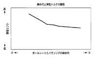
- FIG. 13 is an explanatory view showing the relationship between the tightening allowance between the ball seat and the housing incorporated in the ball joint device and the elastic lift. It can be seen that the elastic lift increases as the tightening margin is reduced.
- an object of the present invention is to provide a ball joint device capable of reducing the swinging sliding torque without increasing the elastic lift.
- a ball joint device includes a ball seat made of a resin material having a concave spherical surface and an outer peripheral surface, a stud ball having a spherical head rotatably fitted to the concave spherical surface, and A ball seat is inserted and accommodated from the opening toward the bottom surface, and includes a housing having a concave portion into which the inner peripheral surface and the outer peripheral surface of the ball seat are fitted, and the outer diameter of the outer peripheral surface is the bottom surface Further, the inner diameter of the inner peripheral surface has a region that extends at least from the bottom surface toward the opening.
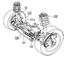
- FIG. 1 is a perspective view showing a vehicle stabilizer incorporating a ball joint device according to an embodiment of the present invention and a vehicle front wheel suspension device.
- FIG. 2 is an exploded cross-sectional view of the ball joint device.
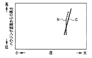
- FIG. 3 is an explanatory view showing the relationship between the inner diameter of the inner peripheral surface of the housing incorporated in the ball joint device and the outer diameter of the outer peripheral surface of the ball seat.
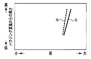
- FIG. 4 is an explanatory diagram showing the relationship between the inner diameter of the inner peripheral surface of the housing and the outer diameter of the outer peripheral surface of the ball seat according to the first modification incorporated in the ball joint device.
- FIG. 1 is a perspective view showing a vehicle stabilizer incorporating a ball joint device according to an embodiment of the present invention and a vehicle front wheel suspension device.
- FIG. 2 is an exploded cross-sectional view of the ball joint device.
- FIG. 3 is an explanatory view showing the relationship between the inner diameter of the inner peripheral surface of the housing incorporated in the ball joint device and the outer diameter
- FIG. 5 is an explanatory diagram showing the relationship between the inner diameter of the inner peripheral surface of the housing and the outer diameter of the outer peripheral surface of the ball seat according to the second modification incorporated in the ball joint device.
- FIG. 6 is an explanatory diagram showing the relationship between the inner diameter of the inner peripheral surface of the housing and the outer diameter of the outer peripheral surface of the ball seat according to the third modification incorporated in the ball joint device.
- FIG. 7 is a cross-sectional view showing an example of a ball joint device.
- FIG. 8 is a cross-sectional view showing a housing incorporated in the ball joint device.
- FIG. 9 is an explanatory view showing the relationship between the inner diameter of the inner peripheral surface of the housing incorporated in the ball joint device and the outer diameter of the outer peripheral surface of the ball seat.
- FIG. 10 is an explanatory view showing the relationship between the load and the deflection before the test in the ball joint device in comparison with a normal ball seat and a low torque ball seat.
- FIG. 11 is an explanatory view showing the relationship between the load and the deflection after the test in the ball joint device in comparison with a normal ball seat and a low torque ball seat.
- FIG. 12 is an explanatory view showing the relationship between the tightening allowance between the ball seat and the housing incorporated in the ball joint device and the swinging sliding torque.
- FIG. 13 is an explanatory view showing the relationship between the tightening allowance between the ball seat and the housing incorporated in the ball joint device and the elastic lift.
- FIG. 1 is a perspective view showing a vehicle stabilizer 100 and a vehicle front wheel suspension device 200 in which a ball joint device 10 according to an embodiment of the present invention is incorporated
- FIG. 2 is an exploded sectional view showing the ball joint device 10. It is.
- a vehicle stabilizer 100 includes a stabilizer bar 101 formed of a hollow member, a fixing member 102 that fixes the stabilizer bar 101 to a frame portion (not shown) of a vehicle body, and a tip 101 a of the stabilizer bar 101. And a stabilizer link 110 that connects the operating part of the suspension device 200 to the operating part.
- the ball joint device 10 constitutes a part of the stabilizer link 110.
- the ball joint device 10 includes a metal housing 12.
- the housing 12 is a press-formed product made of a single metal plate such as a steel plate, and is formed by drawing.
- the housing 12 has a ball sheet insertion portion (concave portion) 20 that has been drawn into a cylindrical shape, a bottom surface 21 located at an end of the ball sheet insertion portion 20, and an inner peripheral surface 22.
- a flange portion 24 is provided in the opening 23 of the ball seat insertion portion 20.
- a plurality of holes 25 are punched in the bottom surface 21.
- the inner diameter N of the inner peripheral surface 22 is constant from the bottom surface 21 to the midway portion 22a, and widens from the midway portion 22a toward the opening 23 side.
- the ball sheet 30 is accommodated in the ball sheet insertion portion 20.
- the ball sheet 30 is made of, for example, a thermoplastic synthetic resin such as polyacetal or polybutylene terephthalate, and has a bottomed cylindrical shape.
- the ball sheet 30 has a concave spherical surface 31 inside, a protrusion 32 at the bottom, and an outer peripheral surface 33. is doing.
- the outer diameter G of the outer peripheral surface 33 extends from the bottom surface 21 side toward the opening 23 side.
- a plurality of protrusions 32 are provided on the bottom surface of the ball sheet 30 at positions corresponding to the holes 25. After the protrusion 32 is inserted into the hole 25, the portion 32a where the protrusion 32 protrudes outside the hole 25 is softened by applying heat from the outside or generating heat by high frequency induction, and crushing the portion 32a in the axial direction.
- the ball seat 30 is fixed to the housing 12.
- the spherical head 41 of the stud ball 40 is rotatably fitted to the concave spherical surface 31 of the ball seat 30.
- the stud ball 40 includes a screw portion 42 and a large diameter portion 43 in addition to the spherical head portion 41.
- the outer diameter G of the outer peripheral surface is formed smaller than the inner diameter N of the inner peripheral surface on the bottom surface side of the recess and larger than the inner diameter N of the inner peripheral surface on the opening side of the recess.
- the steady swing torque / rotational torque is preferably 1.0 Nm or less.
- the housing 12 is press-molded and can be molded without machining. For this reason, the existing production line does not need to be significantly modified, and the existing production cost and product cost can be minimized.
- the outer diameter G of the outer peripheral surface is formed larger than the inner diameter N of the inner peripheral surface, and the difference between the outer diameter G of the outer peripheral surface and the inner diameter N of the inner peripheral surface is the bottom surface. It is set to monotonously increase from the 21 side toward the opening 23 side.
- the difference between the outer diameter G of the outer peripheral surface and the inner diameter N of the inner peripheral surface is constant from the bottom surface 21 side to the midway portion, and monotonously increases from the midway portion toward the opening side. Is set to
- the difference between the outer diameter G of the outer peripheral surface and the inner diameter N of the inner peripheral surface is constant from the bottom surface 21 side to the opening.
- the main stress is uniform as in the case of the solid member. Can be realized by a simple design and manufacturing method.
Landscapes
- Engineering & Computer Science (AREA)
- General Engineering & Computer Science (AREA)
- Mechanical Engineering (AREA)
- Pivots And Pivotal Connections (AREA)
- Vehicle Body Suspensions (AREA)
Abstract
Description
Claims (6)
- 凹球面及び外周面とを有する樹脂材製のボールシートと、
上記凹球面に回転自在に嵌合する球状頭部を有するスタッドボールと、
上記ボールシートを開口部から底面側に向けて挿入して収容し、その内周面と上記ボールシートの外周面が嵌合する凹部を有するハウジングとを備え、
上記外周面の外径は、上記底面側から上記開口部側に向けて拡がっており、また、上記内周面の内径は、上記底面から上記開口部側に向けて少なくとも拡がる領域を有していることを特徴とするボールジョイント装置。 - 上記外周面の外径は、上記凹部の底面側で上記内周面の内径より小、上記凹部の開口部側で上記内周面の内径より大に形成されていることを特徴とする請求項1に記載のボールジョイント装置。
- 上記外周面の外径は、上記内周面の内径より大に形成されていることを特徴とする請求項1に記載のボールジョイント装置。
- 上記外周面の外径と上記内周面の内径との差は、上記底面側から上記開口部側に向けて単調増加することを特徴とする請求項3に記載のボールジョイント装置。
- 上記外周面の外径と上記内周面の内径との差は、上記底面側から中途部まで一定、上記中途部から上記開口部側に向けて単調増加することを特徴とする請求項3に記載のボールジョイント装置。
- 上記外周面の外径と上記内周面の内径との差は、上記底面側から上記開口部まで一定であることを特徴とする請求項3に記載のボールジョイント装置。
Priority Applications (3)
| Application Number | Priority Date | Filing Date | Title |
|---|---|---|---|
| CN201180009587.7A CN102753847B (zh) | 2010-02-16 | 2011-02-16 | 球形接头装置 |
| DE112011100552.0T DE112011100552B4 (de) | 2010-02-16 | 2011-02-16 | Kugelgelenkvorrichtung |
| US13/570,500 US8657520B2 (en) | 2010-02-16 | 2012-08-09 | Ball joint apparatus |
Applications Claiming Priority (2)
| Application Number | Priority Date | Filing Date | Title |
|---|---|---|---|
| JP2010031745A JP5165011B2 (ja) | 2010-02-16 | 2010-02-16 | ボールジョイント装置 |
| JP2010-031745 | 2010-02-16 |
Related Child Applications (1)
| Application Number | Title | Priority Date | Filing Date |
|---|---|---|---|
| US13/570,500 Continuation US8657520B2 (en) | 2010-02-16 | 2012-08-09 | Ball joint apparatus |
Publications (1)
| Publication Number | Publication Date |
|---|---|
| WO2011102372A1 true WO2011102372A1 (ja) | 2011-08-25 |
Family
ID=44482957
Family Applications (1)
| Application Number | Title | Priority Date | Filing Date |
|---|---|---|---|
| PCT/JP2011/053255 Ceased WO2011102372A1 (ja) | 2010-02-16 | 2011-02-16 | ボールジョイント装置 |
Country Status (5)
| Country | Link |
|---|---|
| US (1) | US8657520B2 (ja) |
| JP (1) | JP5165011B2 (ja) |
| CN (1) | CN102753847B (ja) |
| DE (1) | DE112011100552B4 (ja) |
| WO (1) | WO2011102372A1 (ja) |
Families Citing this family (8)
| Publication number | Priority date | Publication date | Assignee | Title |
|---|---|---|---|---|
| JP5189145B2 (ja) * | 2010-08-23 | 2013-04-24 | 日本発條株式会社 | スタビリンクおよびその製造方法 |
| JP5728103B1 (ja) * | 2014-02-18 | 2015-06-03 | 日本発條株式会社 | リンクアーム部材 |
| JP5923189B1 (ja) * | 2015-02-17 | 2016-05-24 | 日本発條株式会社 | スタビリンク |
| KR101732063B1 (ko) | 2015-04-29 | 2017-05-08 | 주식회사 일진 | 볼 조인트 일체형 자동차용 하이브리드 암 및 그 제조 방법 |
| JP6300772B2 (ja) | 2015-10-02 | 2018-03-28 | 日本発條株式会社 | ボールジョイント |
| CN109281924B (zh) * | 2018-11-19 | 2020-10-23 | 广西天正钢结构有限公司 | 外包自收口的钢结构接头及其制造方法 |
| DE102019204659A1 (de) * | 2019-04-02 | 2020-10-08 | Zf Friedrichshafen Ag | Kugelgelenk für ein Fahrwerk eines Fahrzeugs und Verfahren zum Herstellen eines solchen Kugelgelenks |
| JP7175856B2 (ja) * | 2019-07-17 | 2022-11-21 | 日本発條株式会社 | ボールシート、ボールジョイント及びボールジョイントの製造方法 |
Citations (2)
| Publication number | Priority date | Publication date | Assignee | Title |
|---|---|---|---|---|
| JPH08159147A (ja) * | 1994-12-08 | 1996-06-18 | Somic Ishikawa:Kk | ロッドエンド軸受装置 |
| JP2002295444A (ja) * | 2001-04-04 | 2002-10-09 | Nhk Spring Co Ltd | ボールジョイントおよびそのハウジングの製造方法 |
Family Cites Families (9)
| Publication number | Priority date | Publication date | Assignee | Title |
|---|---|---|---|---|
| JPH06104751B2 (ja) | 1989-11-29 | 1994-12-21 | 出光石油化学株式会社 | 多孔性フィルム,シート及びその製造方法 |
| US5163769A (en) * | 1991-01-30 | 1992-11-17 | Trw, Inc. | Ball joint having service life indicator |
| JP3168229B2 (ja) * | 1992-10-06 | 2001-05-21 | 日本発条株式会社 | ボールジョイント装置 |
| JP3369659B2 (ja) * | 1993-08-06 | 2003-01-20 | 日本発条株式会社 | ボールジョイント |
| US5997208A (en) * | 1998-06-02 | 1999-12-07 | Trw Inc. | Adjustment for a ball joint assembly |
| JP4514297B2 (ja) * | 2000-09-11 | 2010-07-28 | 日本発條株式会社 | ボールジョイントおよびその組立方法 |
| US6824300B2 (en) * | 2002-06-19 | 2004-11-30 | Guide Corporation | Headlamp mounting plug |
| DE102005027825A1 (de) * | 2005-06-15 | 2007-01-04 | Zf Friedrichshafen Ag | Kugelgelenk mit Sensoreinrichtung und Verfahren zur Dichtigkeitserkennung |
| CN201180735Y (zh) * | 2007-12-05 | 2009-01-14 | 东风汽车有限公司设备制造厂 | 一种球头销总成 |
-
2010
- 2010-02-16 JP JP2010031745A patent/JP5165011B2/ja active Active
-
2011
- 2011-02-16 CN CN201180009587.7A patent/CN102753847B/zh active Active
- 2011-02-16 DE DE112011100552.0T patent/DE112011100552B4/de active Active
- 2011-02-16 WO PCT/JP2011/053255 patent/WO2011102372A1/ja not_active Ceased
-
2012
- 2012-08-09 US US13/570,500 patent/US8657520B2/en active Active
Patent Citations (2)
| Publication number | Priority date | Publication date | Assignee | Title |
|---|---|---|---|---|
| JPH08159147A (ja) * | 1994-12-08 | 1996-06-18 | Somic Ishikawa:Kk | ロッドエンド軸受装置 |
| JP2002295444A (ja) * | 2001-04-04 | 2002-10-09 | Nhk Spring Co Ltd | ボールジョイントおよびそのハウジングの製造方法 |
Also Published As
| Publication number | Publication date |
|---|---|
| DE112011100552T5 (de) | 2012-11-22 |
| US20120301213A1 (en) | 2012-11-29 |
| CN102753847A (zh) | 2012-10-24 |
| CN102753847B (zh) | 2015-01-07 |
| JP2011169353A (ja) | 2011-09-01 |
| US8657520B2 (en) | 2014-02-25 |
| JP5165011B2 (ja) | 2013-03-21 |
| DE112011100552T9 (de) | 2014-08-28 |
| DE112011100552B4 (de) | 2020-12-17 |
Similar Documents
| Publication | Publication Date | Title |
|---|---|---|
| JP5165011B2 (ja) | ボールジョイント装置 | |
| JP7156637B2 (ja) | ブッシュ及び車両用サスペンション装置 | |
| JP7140767B2 (ja) | ブッシュ配置構造 | |
| WO2016013337A1 (ja) | 車両用ペダル装置の軸受部構造および鍔付きブッシュ | |
| CN101909911A (zh) | 车辆稳定器 | |
| US12179533B1 (en) | Stabilizer bar assembly and vehicle including the same | |
| WO2016132885A1 (ja) | スタビリンク | |
| JP3820361B2 (ja) | スプリングシートラバー | |
| US11473646B2 (en) | Bushing and vehicle suspension device | |
| KR101580428B1 (ko) | 차량용 스테빌라이저 바 마운팅 부시 | |
| JP4751743B2 (ja) | サスペンションブッシュおよびそれを用いたダブルジョイント式サスペンション機構 | |
| JP2013166480A (ja) | ブッシュ | |
| CN212928661U (zh) | 轴承衬套、EPSc蜗杆端部预紧结构及蜗轮蜗杆装配结构 | |
| JP2006160008A (ja) | サスペンションアーム支持構造 | |
| JPWO2018198412A1 (ja) | トルクロッド | |
| JP4743004B2 (ja) | サスペンション構造 | |
| JP6601436B2 (ja) | ブッシュ付きリーフスプリング | |
| JP4666692B2 (ja) | 防振ブッシュおよびその製造方法 | |
| JP5246296B2 (ja) | サスペンション構造、ブッシュ構造、サスペンション特性調整方法 | |
| JP2019052725A (ja) | トルクロッド | |
| JP5876267B2 (ja) | スタビライザブッシュおよび軸受装置 | |
| JP2004225757A (ja) | ゴムブッシュ | |
| JP2026009620A (ja) | 防振装置、及び防振装置の製造方法 | |
| JP2025069869A (ja) | スタビライザブッシュ | |
| US20050274213A1 (en) | Actuator assembly for suspension |
Legal Events
| Date | Code | Title | Description |
|---|---|---|---|
| WWE | Wipo information: entry into national phase |
Ref document number: 201180009587.7 Country of ref document: CN |
|
| 121 | Ep: the epo has been informed by wipo that ep was designated in this application |
Ref document number: 11744658 Country of ref document: EP Kind code of ref document: A1 |
|
| WWE | Wipo information: entry into national phase |
Ref document number: 112011100552 Country of ref document: DE Ref document number: 1120111005520 Country of ref document: DE |
|
| 122 | Ep: pct application non-entry in european phase |
Ref document number: 11744658 Country of ref document: EP Kind code of ref document: A1 |