WO2011102166A1 - 記録テープカートリッジ - Google Patents
記録テープカートリッジ Download PDFInfo
- Publication number
- WO2011102166A1 WO2011102166A1 PCT/JP2011/050678 JP2011050678W WO2011102166A1 WO 2011102166 A1 WO2011102166 A1 WO 2011102166A1 JP 2011050678 W JP2011050678 W JP 2011050678W WO 2011102166 A1 WO2011102166 A1 WO 2011102166A1
- Authority
- WO
- WIPO (PCT)
- Prior art keywords
- case
- base portion
- recording tape
- tape cartridge
- base
- Prior art date
- Legal status (The legal status is an assumption and is not a legal conclusion. Google has not performed a legal analysis and makes no representation as to the accuracy of the status listed.)
- Ceased
Links
Images










Classifications
-
- G—PHYSICS
- G11—INFORMATION STORAGE
- G11B—INFORMATION STORAGE BASED ON RELATIVE MOVEMENT BETWEEN RECORD CARRIER AND TRANSDUCER
- G11B23/00—Record carriers not specific to the method of recording or reproducing; Accessories, e.g. containers, specially adapted for co-operation with the recording or reproducing apparatus ; Intermediate mediums; Apparatus or processes specially adapted for their manufacture
- G11B23/02—Containers; Storing means both adapted to cooperate with the recording or reproducing means
- G11B23/04—Magazines; Cassettes for webs or filaments
- G11B23/08—Magazines; Cassettes for webs or filaments for housing webs or filaments having two distinct ends
- G11B23/107—Magazines; Cassettes for webs or filaments for housing webs or filaments having two distinct ends using one reel or core, one end of the record carrier coming out of the magazine or cassette
-
- G—PHYSICS
- G11—INFORMATION STORAGE
- G11B—INFORMATION STORAGE BASED ON RELATIVE MOVEMENT BETWEEN RECORD CARRIER AND TRANSDUCER
- G11B23/00—Record carriers not specific to the method of recording or reproducing; Accessories, e.g. containers, specially adapted for co-operation with the recording or reproducing apparatus ; Intermediate mediums; Apparatus or processes specially adapted for their manufacture
- G11B23/02—Containers; Storing means both adapted to cooperate with the recording or reproducing means
- G11B23/04—Magazines; Cassettes for webs or filaments
- G11B23/041—Details
- G11B23/042—Auxiliary features
Definitions
- the present invention relates to a recording tape cartridge in which a first communication unit that communicates with the outside by an electromagnetic induction method and a second communication unit that communicates with the outside by a radio wave method.
- a magnetic tape cartridge in which an RFID tag that operates in the UHF band is disposed along the inner surface of the rear wall portion of the cartridge case (see, for example, Japanese Patent Application Laid-Open No. 2007-257744).
- an IC tag including two antennas and two IC chips having different communication frequency bands (see, for example, JP-A-2007-324638). In this configuration, one antenna is arranged so as to be overlapped in the thickness direction so as to be orthogonal to a part of the other antenna, and interference between the two antennas is suppressed.
- An object of the present invention is to obtain a recording tape cartridge capable of satisfactorily incorporating two communication units having different communication methods in a case.
- a recording tape cartridge includes a reel on which a recording tape is wound, a case in which the reel is accommodated, a first base portion provided in the case, and the first
- a first communication unit having a first element unit provided in a base unit and a first antenna provided in the first base unit and communicating with the outside of the case by an electromagnetic induction method;
- a second element portion provided on the first base portion, a second base portion connected to the first base portion so as to be handled integrally with the first base portion, and a second base portion provided on the second base portion.
- a second communication unit that communicates with the outside of the case by a radio wave method.
- the first communication unit built in the case communicates with the outside of the case by the electromagnetic induction method
- the second communication unit built in the case communicates with the outside of the case by the radio wave method.
- the second base part configuring the second communication unit is configured to be handled as one unit with the first base unit configuring the first communication unit. For this reason, when the first communication unit is incorporated (positioned) in the case, the second communication unit is arranged at a required position with respect to the case. Moreover, since the 2nd element part (communication circuit part) which comprises a 2nd communication part is provided in the 1st base, the 2nd communication part has few restrictions with respect to arrangement
- the second communication unit in the present recording tape cartridge has an element part provided on the first base part, so that the arrangement restriction is required to protect the second element part from interference with the movable body with respect to the case. Not receive. Therefore, the 2nd base and 2nd antenna which constitute the 2nd communication part can be arranged in the place on space efficiency or communication, for example in a case.
- two communication units having different communication methods can be favorably incorporated in the case.
- the second communication unit is set to have a longer communicable distance than the first communication unit.
- the second communication unit since the second communication unit has a relatively long communication distance, the second antenna unit is required to be enlarged.
- the degree of freedom in arrangement of the second antenna in the case is required. Therefore, it is easy to increase the size of the second antenna.
- the second element portion is configured integrally with the first element portion.
- the structure is simpler than the structure having two elements having separate functions. It becomes.
- the second base is configured integrally with the first base.
- the electrical connection structure between each element portion and the antenna portion can be integrally formed.
- the first base portion is disposed so as to be inclined with respect to the peripheral wall and the bottom plate so as to face both the peripheral wall and the bottom plate of the case
- the second base portion includes the case.
- the first base that is, the first antenna is inclined with respect to the case peripheral wall and the bottom plate
- the second base that is, the second antenna
- the first and second antennas are arranged according to the required communication direction.
- the first base portion and the second base portion are connected to each other at the other end side of the slit opened at one end side, and the connecting portion has a flexible deformation allowance. It is considered to be a part.
- the first and second base portions are connected by the flexible deformation allowing portion which is the uncut portion on the other end side of the slit.
- transformation permission part WHEREIN The 1st base part inclined with respect to the case surrounding wall and the baseplate, and the 2nd arrange
- the first base portion faces the back wall and the bottom plate of the case facing the opposite side of the circumferential wall of the case from the leading side in the loading direction to the drive device. It is arranged to be inclined with respect to the back wall and the bottom plate at the corners in the case, and the second base is arranged from the first base to the first base along the back wall.
- the case is extended toward a corner portion located on the opposite side of the corner portion of the case.
- the first communication unit is disposed at one corner of the case on the back wall side, and the second base portion extends from the one corner to the other corner. It extends along the back wall.
- the first base portion is inclined as described above at the corners having a relatively large distance from the reel, and the second base is a vertical wall between the corners having a relatively small distance from the reel. Arranged along.
- the case has an inner wall standing upright from a bottom plate and a top plate of the case so as to cover the reel from the outside in the radial direction, and the first base portion is formed on the peripheral wall of the case. Inclined with respect to the back wall and the bottom plate at the corners of the case so as to face both the back wall facing the opposite side of the loading direction to the drive device and the bottom plate of the case.
- the second base portion extends along the inner wall separating the corner corner portion of the case where the first base portion is disposed and the installation space of the reel.
- the first communication unit is disposed at one corner of the case on the back wall side of the case, and the second communication is performed along the inner wall separating the one corner from the reel arrangement region.
- the base is extended.
- the first base portion is inclined and disposed at the corner portion having a relatively large distance from the reel, and the second base portion is disposed along the inner wall that separates the corner portion from the reel placement space. That is, the first base and the second base are arranged at a common corner.
- the first base portion faces the back wall and the bottom plate of the case facing the opposite side of the circumferential wall of the case from the leading side in the loading direction to the drive device.
- the corners in the case are arranged to be inclined with respect to the back wall and the bottom plate, and the second base part is arranged from the first base part to the corner in which the first base part in the case is arranged. It extends along at least one of the back wall, the bottom plate, and the top plate constituting the corner.
- the first communication unit is inclinedly arranged as described above at one corner corner on the back wall side in the case, and the back wall constituting (defining) the one corner portion,
- a second base extends along at least one of the bottom plate and the top wall. Both the first base portion and the second base portion are arranged at corners having a relatively large distance from the reel.
- the recording tape cartridge of the above aspect further includes a reinforcing member that holds the first base material and the second base material in a posture built in the case.
- the first and second communication units are held in the built-in posture in the case by the reinforcing member.
- position beforehand to a case can be easily incorporated in a case.
- the first and second communication units can be configured to maintain the posture in the case without depending on the standing wall of the case.
- a slit is formed in the second base portion so as to straddle an inner wall erected from a top plate or a bottom plate in the case, and the inner wall has the slit in the second base portion.
- a slit is formed to allow an uncut portion of the slit to enter.
- the inner wall of the case and the second base part allow the slit uncut portion to enter the counterpart slit, and the second communication part is built in the case.
- a 2nd base will be installed ranging over an inner wall, and it can enlarge a 2nd antenna.
- the second base is positioned with respect to the case.
- the recording tape cartridge according to the present invention has an excellent effect that two communication units having different communication methods can be favorably incorporated in the case.
- FIG. 3 is a perspective view showing a main part of the recording tape cartridge according to the first embodiment of the invention.
- FIG. 3 is an exploded perspective view showing a main part of the recording tape cartridge according to the first embodiment of the present invention.
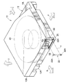
- 1 is a perspective view showing an external appearance of a recording tape cartridge according to a first embodiment of the present invention.
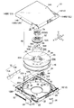
- FIG. 3 is an exploded perspective view of the recording tape cartridge according to the first embodiment of the present invention as viewed from above.
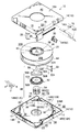
- FIG. 3 is an exploded perspective view seen from the lower side of the recording tape cartridge according to the first embodiment of the present invention.
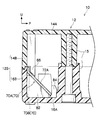
- FIG. 3 is a cross-sectional view showing a mounting structure of a memory board part constituting the recording tape cartridge according to the first embodiment of the invention.
- 1 is a perspective view showing a composite communication device constituting a recording tape cartridge according to a first embodiment of the present invention.
- 1 is a perspective view showing a posture in which a composite communication device constituting a recording tape cartridge according to a first embodiment of the present invention is built in a case.
- 1 is a front view showing a composite communication device constituting a recording tape cartridge according to a first embodiment of the present invention. It is a perspective view which shows the principal part of the recording tape cartridge which concerns on the 2nd Embodiment of this invention. It is a perspective view which shows the attitude
- FIG. 9 is a perspective view showing a posture in which a composite communication device constituting a recording tape cartridge according to a third embodiment of the present invention is built in a case. It is a front view which shows the composite communication device which comprises the recording tape cartridge which concerns on the 3rd Embodiment of this invention. It is sectional drawing which shows the attachment structure of the memory board part which comprises the recording tape cartridge which concerns on the 3rd Embodiment of this invention. It is a perspective view which shows the principal part of the recording tape cartridge which concerns on the 4th Embodiment of this invention.
- a recording tape cartridge 10 according to the first embodiment of the present invention will be described with reference to FIGS. First, the overall configuration of the recording tape cartridge 10 will be described, and then the composite communication device 70 built in the recording tape cartridge 10 and the internal structure of the composite communication device 70 will be described.
- the arrow U direction shown in each figure as appropriate is the upward direction
- the arrow F direction is the forward direction (loading direction to the drive device)
- the arrow R direction is the right direction
- the arrow L direction is the left direction.
- these directions do not limit the posture of the recording tape cartridge 10.
- FIG. 3 is a perspective view showing the external appearance of the recording tape cartridge 10.
- 4 shows an exploded perspective view of the recording tape cartridge 10 as viewed from above
- FIG. 5 shows an exploded perspective view of the recording tape cartridge 10 as viewed from below.
- the recording tape cartridge 10 includes a case 12.
- the case 12 is configured by joining an upper case 14 made of a resin that opens downward and a lower case 16 made of a resin that opens upward so that the opening ends thereof are brought into contact with each other.
- the case 12 has a substantially rectangular shape (square shape) in plan view and is configured as a flat case that is thin in the vertical direction.
- the upper case 14 is configured such that an outer peripheral wall 14B is erected downward from a peripheral portion of a substantially rectangular top plate 14A in a plan view.
- the lower case 16 is configured by an outer peripheral wall 16B standing upward from a peripheral edge portion of a substantially rectangular bottom plate 16A in plan view.
- the case 12 is configured by joining the upper case 14 and the lower case 16 with the open ends of the outer peripheral wall 14B and the outer peripheral wall 16B being abutted against each other.
- screws (not shown) screws whose heads are accommodated in the lower screw bosses 15 are brought into contact with the screw bosses 15 protruding from the top plate 14A of the upper case 14 and the bottom plate 16A of the lower case 16.
- the part is screwed into the upper screw boss 15. Thereby, the upper case 14 and the lower case 16 are joined.
- a single reel 20 around which a magnetic tape T as a recording tape is wound is rotatably accommodated.
- the magnetic tape T wound around the reel 20 is drawn out of the case 12 through an opening 18 formed on the front end side of the right side wall 12R of the case 12 in a drive device (not shown).
- Information is read from and written to the magnetic tape T drawn from the case 12 through the opening 18.
- a leader pin 22 as a leader member that is operated (held) when the magnetic tape T is pulled out by the drive device is attached to the tip of the magnetic tape T.
- the leader pin 22 is formed at both ends thereof, and the flange 22A protruding from the end portion in the width direction of the magnetic tape T is inserted into the pin receiving recess 24 provided at the position facing the opening 18 in the case 12,
- the case 12 is held at a predetermined position.
- the case 12 is provided with a spring 26 for holding the posture of the leader pin 22 with respect to the case 12 by pressing the flange 22A against the concave wall of the pin receiving recess 24.
- the leader pin 22 is pulled out of the case 12 together with the magnetic tape T, with the narrow shaft portion between the flange 22A and the magnetic tape T being hooked by a pull-out member of the drive device.
- the opening 18 of the case 12 is opened and closed by a door 28 as an opening / closing member.
- the door 28 is configured to open and close the opening 18 by sliding in the front-rear direction while being guided by a guide groove 25 formed along the right side wall 12R including the outer peripheral wall 14B and the outer peripheral wall 16B.
- the door 28 is urged by a door spring 30 in a direction to close the opening 18.
- the case 12 is provided with a reel area rib 32 as an inner wall that is an upright wall portion provided so as to cover the reel 20 from the radially outer side (outer peripheral side).
- the reel area rib 32 is configured by joining halves erected from the top plate 14A and the bottom plate 16A, respectively, and surrounds a reel space 34 in which the reel 20 is disposed.
- a plurality of reel area ribs 32 are partially erected in the circumferential direction, and each circumferential end is connected to the outer peripheral wall 14B and the outer peripheral wall 16B via a connecting wall 36 as an inner wall.
- the connecting wall 36 is not connected to the circumferential end of the reel area rib 32 located in the vicinity of the opening 18 to form the guide groove 25, and the screw boss 15 is integrated to ensure strength. .
- a reel opening 42 for exposing the reel gear 38 and the magnetic metal reel plate 40 provided at the bottom 35A of the reel hub 35 that forms the axial center of the reel 20 is provided at a substantially central portion of the bottom plate 16A of the case 12. Is formed.
- a rotary shaft (not shown) of the drive device is configured to rotate the reel 20 by meshing the drive gear with the reel gear 38 while attracting and holding the reel plate 40 with a magnet.
- the reel 20 has a pair of upper and lower flanges 44 and 46 that regulate displacement in the width direction of the magnetic tape T wound around the outer peripheral surface of the reel hub 35. That is, the magnetic tape T is wound between the flanges 44 and 46. Further, a lock mechanism 48 for locking and unlocking the rotation of the reel 20 with respect to the case 12 is provided in the cylindrical portion of the reel hub 35.
- the lock mechanism 48 includes an upward engagement gear 50 provided on the upper surface side of the bottom 35A of the reel hub 35, a brake member 52 having a downward brake gear 52A that can mesh with the engagement gear 50, and a case of the brake member 52. 12, a rotation stopping portion 55 that prohibits rotation with respect to 12, a lock spring 54 that urges the braking member 52 downward so that the braking gear 52 ⁇ / b> A meshes with the engagement gear 50, and a braking member against the urging force of the lock spring 54.
- the release operation member 56 for pushing up 52 is comprised as a main part.
- the rotation stopper 55 is configured by inserting a cross rib 58 protruding from the top plate 14A into the cross groove 60 of the braking member 52 so as to be capable of relative displacement in the vertical direction.
- the release operation member 56 is disposed between the bottom portion 35A and the braking member 52, and moves upward to move the braking member 52 upward so that the engagement of the braking gear 52A with the engagement gear 50, that is, rotation of the reel 20 is performed. The lock state is released.
- the release operation member 56 has leg portions 56B suspended from the tops of the main body 56A formed in a substantially triangular shape in plan view, and penetrates the through holes 35B of the bottom portion 35A.
- the leg portion 56B protrudes between the teeth of the reel gear 38, and is pressed and moved upward by the drive gear of the rotating shaft meshing with the reel gear 38. That is, the lock mechanism 48 is configured such that the rotation lock state of the reel 20 with respect to the case 12 is released as the reel gear 38 engages with the drive gear on the drive device side.
- the release operation member 56 rotates integrally with the reel 20, and a projection 56 ⁇ / b> C provided at the center thereof is in sliding contact with the spherical projection 52 ⁇ / b> B of the braking member 52 that is prevented from rotating with respect to the case 12 with low friction. It has become.
- the recording tape cartridge 10 includes a write protect unit 62 for prohibiting writing of information to the magnetic tape T.
- the write protect unit 62 includes an erroneous erasure prevention plug 64 between a permissible position where the writing of information onto the magnetic tape T is permitted by a user operation and a prohibited position where the writing of information onto the magnetic tape T is prohibited. It is configured to be movable.
- the erroneous erasure prevention plug 64 is configured to be able to take an allowable position and a prohibited position by moving along the rear wall 12B at the rear left corner 12BL of the case 12.
- the accidental erasure prevention plug 64 is disposed across the lower case 16 and the upper case 14.
- the lower guide wall 68 provided substantially parallel to the rear wall 12 B in the lower case 16 and the rear in the upper case 14. It is guided by an upper guide wall 66 provided substantially parallel to the wall 12B.
- the recording tape cartridge 10 described above includes the composite communication device 70 built in the case 12.
- the composite communication device 70 includes a memory board portion 70A as a first communication portion that performs non-contact communication with the outside of the case 12 by electromagnetic induction type short wave (HF), and a UHF band.
- the UHF band RFID tag unit 70B is, for example, information that is conventionally represented by a bar code label or the like attached to the recording tape cartridge 10, unified management of cartridges at the time of storage and transport use by an autoloader (to the magnetic tape T). Information for management in consideration of the relationship with the recorded contents is read / written to / from an IC chip 74 described later.
- the communication distance of the memory board unit 70A is 10 mm to several tens of mm, and the communication distance of the UHF band RFID tag unit 70B is set within a range of about 1 m. That is, the communication distance of the UHF band RFID tag unit 70B is set longer than the communication distance of the memory board unit 70A.
- the memory board unit 70A has a larger recording capacity than the UHF band RFID tag unit 70B.
- the UHF band RFID tag section 70B has a capacity of 96 bits to 120 bits (12B to 15B), whereas the memory board section 70A has a recording capacity of 4 KB to 8 KB.
- the composite communication device 70 includes a base sheet 72 that is a base.
- the base sheet 72 is formed in a film shape and has flexibility. 7 to 9, the base sheet 72 includes a first base portion 72A as a first base portion constituting the memory board portion 70A and a second base portion constituting the UHF band RFID tag portion 70B. As a second base portion 72B.
- the base sheet 72 is made of, for example, a resin material such as polyethylene terephthalate (PET).
- PET polyethylene terephthalate
- the first base portion 72A and the second base portion 72B each having a rectangular shape are integrally formed. Yes.
- the second base portion 72B constituting the UHF band RFID tag portion 70B which requires a long communication distance with respect to the memory board portion 70A, is designed in consideration of the enlargement of the tag antenna 78 described later.
- the longitudinal dimension is set longer than 72A.
- a slit 72C that opens downward is formed between the first base portion 72A and the second base portion 72B.
- a portion of the slit 72C opposite to the opening side is a connecting portion 72D as a left uncut portion that connects the first base portion 72A and the second base portion 72B.
- the flexible base sheet 72 is configured such that the first base portion 72A and the second base portion 72B can take different postures (see FIG. 8) as will be described later by deformation of the connecting portion 72D. Yes. Accordingly, the connecting portion 72D corresponds to the deformation allowing portion of the present invention.
- the memory board portion 70A is configured by forming an IC chip 74 as a first element portion and an antenna 76 as a first antenna on a first base portion 72A.
- the IC chip 74 is disposed at a corner of the first base portion 72A near the connecting portion 72D.
- the IC chip 74 is covered with a protective layer (not shown) in the installed state on the first base portion 72A.
- the antenna 76 is a loop antenna made of a conductive material such as aluminum or copper, and is formed over a plurality of circumferences along the peripheral edge portion of the first base portion 72A. The total extension of the antenna 76 is determined according to a communication frequency (in this embodiment, 13.56 MHz).
- the UHF band RFID tag unit 70B includes an IC chip as a second element unit provided in the first base unit 72A.
- the IC chip constituting the UHF band RFID tag unit 70 ⁇ / b> B is integrated with the IC chip 74.
- the IC chip 74 includes a first circuit unit that performs a communication function (including storage and the like) of the memory board unit 70A, and a communication function of the UHF band RFID tag unit 70B (independent of the first circuit unit).
- the second circuit portion that fulfills (including memory and the like) can be regarded as being configured as a common semiconductor element.
- the UHF band RFID tag unit 70B includes a tag antenna 78 as a second antenna formed on the second base unit 72B and electrically connected to the IC chip 74 (second circuit unit thereof). .
- the tag antenna 78 is made of a conductive material such as aluminum or copper, and is formed substantially symmetrically with respect to the central portion in the longitudinal direction of the second base portion 72B.
- the IC chip 74 and the central portion of the tag antenna 78 are electrically connected by the wiring portion 80.
- the tag antenna 78 according to this embodiment is configured as a kind of so-called dipole antenna formed symmetrically (line symmetric) with respect to the wiring portion 80, that is, the connection portion with the IC chip 74.
- a substantially rectangular radiating portion 78A that is wider than the other portions is formed.
- the portion other than the radiating portion 78A in the tag antenna 78 is a feeding portion 78B, and a plurality of feeding portions 78B are folded back to ensure the total extension of the tag antenna 78 within the dimensions of the second base portion 72B. ing.
- the total extension of the tag antenna 78 is determined according to the communication frequency (in this embodiment, a specific frequency within the range of 860 to 960 MHz).
- the wiring part 80 is made into the structure shielded with respect to the electromagnetic wave so that it may not function as an antenna.
- the composite communication device 70 described above is built in the back side of the case 12 as shown in FIGS.
- the composite communication device 70 is disposed in the lower case 16 constituting the case 12 so as not to protrude from the upper end of the outer peripheral wall 16B in the above posture.
- the memory board portion 70 ⁇ / b> A is disposed in the right rear corner portion 12 ⁇ / b> BR of the case 12 (backward of the opening 18).
- the corner portion 12BR can be regarded as a space outside the reel space 34 mainly surrounded by the rear wall 12B, the right side wall 12R, and the reel area rib 32.
- the UHF band RFID tag portion 70B extends along the rear wall 12B as the back wall from the corner portion 12BR toward the left rear corner portion 12BL in the case 12.
- the corner portion 12BL can be regarded as a space outside the reel space 34 mainly surrounded by the rear wall 12B, the left side wall 12L, and the reel area rib 32.
- the second base portion 72B (tag antenna 78) constituting the UHF band RFID tag portion 70B has one end in the longitudinal direction disposed at the corner corner portion 12BR and the other end in the longitudinal direction is a corner. Arranged at the corner 12BL.
- the second base portion 72B is formed with a slit 72E that opens downward and straddles the connecting wall 36 of the lower case 16. Further, in the vicinity of the boundary portion of the connecting wall 36 with the rear wall 12B, a slit 36A that opens upward and into which the uncut portion 72F above the slit 72E enters is formed.
- the memory board portion 70A is disposed so as to be inclined with respect to each of the rear wall 12B and the bottom plate 16A so as to face both the rear wall 12B and the bottom plate 16A.
- the composite communication device 70 formed flat as shown in FIG. 7 twists and deforms the connecting portion 72D, so that the UHF band RFID tag portion 70B (second base portion) as shown in FIG. 72B), the memory board portion 70A (first base portion 72A) is inclined, that is, the posture is built in the case 12.
- the lower case 16 has inclined ribs 82 formed so as to straddle the rear wall 12B (outer peripheral wall 16B) constituting the corner portion 12BR and the bottom plate 16A.
- the portion 70A is disposed on the inclined rib 82, so that the portion 70A is inclined as described above.
- a stopper rib 84 that is engaged with the front lower end of the memory board portion 70A and restricts the forward movement of the memory board portion 70A is erected from the bottom plate 16A. .
- the upper case 14 has a holding rib 86 formed across the rear wall 12B (outer peripheral wall 16B) and the top plate 14A so as to sandwich and hold the memory board portion 70A with the inclined rib 82.
- the inclined rib 82, the stopper rib 84, and the pressing rib 86 determine the position (posture) of the memory board portion 70A with respect to the case 12 and maintain the posture.
- the UHF band RFID tag unit 70B allows the connection wall 36 to enter the slit 72E and the uncut portion 72F to enter the slit 36A, thereby preventing the case 12 disposed along the rear wall 12B.
- the posture is determined and the posture is maintained.
- the second base portion 72B is disposed in contact with or very close to the rear wall 12B.
- the second base portion 72B may be joined to the rear wall 12B entirely or partially with, for example, an adhesive or a double-sided tape.
- the recording tape cartridge 10 configured as described above is loaded into a drive device when information is written on the magnetic tape T or when information written on the magnetic tape T is read. With this loading operation, the opening 18 is opened, and the drive gear of the rotary shaft is engaged with the reel gear 38 of the reel 20 so that the rotation lock of the reel 20 is released.
- the drive device pulls out the magnetic tape T with the leader pin 22 at the head and sets the leader pin 22 on the reel on the drive device side, the head provided in the tape path while being driven to rotate synchronously with the reel and the reel 20. The information is written to and read from the magnetic tape T.
- the reel 20 is reversed and the magnetic tape T is wound around the reel 20, and then the leader pin 22 is held in the pin receiving recess 24.
- the rotation of the reel 20 relative to the case 12 is locked by the braking member 52 and the opening 18 is closed by the door 28.
- the memory board unit 70 ⁇ / b> A drives various information such as individual identification information of the recording tape cartridge 10, manufacturing information, recording capacity and recording format of the magnetic tape T, and information recording range Perform contactless communication with the device.
- the communication unit of the drive device communicates with the memory board unit 70A from below the bottom plate 16A with a communication distance of several tens of mm.
- the memory board unit 70A performs non-contact communication with the outside as necessary.
- the external communication unit communicates with the memory board unit 70A at a communication distance of several tens of mm from the rear of the rear wall 12B.
- the UHF band RFID tag unit 70B has previously managed information such as bar code, inventory information, theft / loss information, information for preventing unauthorized take-out, etc. Wireless communication with the outside is performed at a communication distance of 1 m or less.
- the first base portion 72A of the memory board portion 70A and the second base portion 72B of the UHF band RFID tag portion 70B are connected via a connecting portion 72D.
- the memory board part 70A and the UHF band RFID tag part 70B can be integrally handled as a subassembly, so that the memory board part 70A is built in (positioned) with respect to the case 12.
- the UHF band RFID tag part 70B is arranged at a required position with respect to the case 12.
- the IC chip (a part of the IC chip 74) constituting the UHF band RFID tag unit 70B is provided in the first base unit 72A constituting the memory board unit 70A, the arrangement of the UHF band RFID tag unit 70B can be reduced. There are fewer constraints. That is, the IC chip has a restriction in arrangement for protection from interference with the movable body with respect to the case 12 such as the reel 20, but the UHF band RFID tag unit 70B is provided in the first base unit 72A. Therefore, there is no restriction on the arrangement for protecting the IC chip against interference with the reel 20 or the like.
- the reel 20 of the IC chip 74 disposed in the corner portion 12BR.
- the structure which prevents interference with is realized. Therefore, for example, the second base portion 72B provided with the tag antenna 78 can be disposed at a suitable place in space 12 or in communication in the case 12.
- the two communication units having different communication methods that is, the memory board unit 70A and the UHF band RFID tag unit 70B can be favorably incorporated in the case 12.
- the tag antenna 78 is required to be larger than the antenna 76.
- the degree of freedom of arrangement of the tag antenna 78 in the case 12 is high as described above, the tag antenna 78 can be easily enlarged.
- the IC chip (function) constituting the UHF band RFID tag unit 70B is integrally formed with the IC chip 74 of the memory board unit 70A. For this reason, the structure of the composite communication device 70 is simpler than the configuration in which the IC chip for the memory board unit 70A and the IC chip for the UHF band RFID tag unit 70B are provided.
- the first base portion 72A and the second base portion 72B are integrally formed as a base sheet 72. Therefore, the wiring portion 80 that electrically connects the IC chip 74 and the tag antenna 78 can be integrally formed as a whole. For this reason, the composite communication device 70 has a simple structure as a single unit and can be manufactured at low cost, and does not require connection work after being incorporated in the case 12, thereby contributing to a reduction in manufacturing cost of the recording tape cartridge 10.
- the UHF band RFID tag portion 70B is disposed along the rear wall 12B of the case 12, so that a tag that is required to be enlarged as described above.
- the antenna 78 is easy to arrange.
- the memory board portion 70A is disposed to be inclined with respect to the rear wall 12B and the bottom plate 16A, but the connecting portion 72D of the base sheet 72 has flexibility. For this reason, a difference in the built-in posture (orientation) between the memory board portion 70A (first base portion 72A) and the UHF band RFID tag portion 70B (second base portion 72B) is allowed due to the deformation of the connecting portion 72D. Thereby, the antenna 76 and the tag antenna 78 can be arranged in directions corresponding to the respective communication directions.
- FIG. 10 is a perspective view corresponding to FIG. 1 showing a main part of a recording tape cartridge 90 according to the second embodiment of the present invention.
- the recording tape cartridge 90 is different from the recording tape cartridge 10 according to the first embodiment in that it includes a composite communication device 92 instead of the composite communication device 70.
- the composite communication device 92 has a UHF band RFID tag portion 92B as a second communication portion disposed along the reel area rib 32 that defines the corner portion 12BR.
- the composite communication device 92 includes a memory board part 92A as a first communication part configured in the same manner as the memory board part 70A and a UHF band RFID tag part 92B as main parts.
- the base sheet 94 constituting the composite communication device 92 has a first base portion 94A and a second base portion 94B.
- the first base portion 94A is formed in the same manner as the first base portion 72A, is provided with an IC chip 74 and an antenna 76, and constitutes a memory board portion 92A.
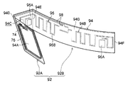
- the second base portion 94B is formed in a rectangular shape like the UHF band RFID tag portion 70B. As shown in FIG. 12, a slit 94C and a connecting portion 94D corresponding to the slit 72C and the connecting portion 72D are formed between the first base portion 94A and the second base portion 94B. In addition, a bent portion 94E that is bent to the right is formed on the opposite side of the second base portion 94B to the connecting portion 94D from the first base portion 94A. As a result, the main part of the second base portion 94B is spaced apart (in a non-overlapping state) in front of the first base portion 94A.
- the UHF band RFID tag portion 92B is a curved portion 94G in which a portion from the bent portion 94E to the tip 94F in the second base portion 94B is formed in an arc shape along the reel area rib 32 in a plan view.
- a tag antenna 96 as a second antenna is provided in the curved portion 94G and a portion between the base sheet 94 and the first base portion 94A to constitute a UHF band RFID tag portion 92B.
- the tag antenna 78 and the IC chip 74 are electrically connected by a wiring part 98.
- the tag antenna 96 includes a radiating portion 96A and a power feeding portion 96B, and is configured as a kind of so-called dipole antenna formed symmetrically (line symmetric) with respect to a connection portion with the IC chip 74 (wiring portion 98).
- the other configuration of the recording tape cartridge 90 according to the second embodiment is the same as the corresponding configuration of the recording tape cartridge 10 including a portion not shown.
- the recording tape cartridge 90 according to the second embodiment can basically obtain the same effect by the same operation as that of the recording tape cartridge 10 according to the first embodiment. Further, in the recording tape cartridge 90, since the main part of the UHF band RFID tag portion 92B of the composite communication device 92 has an arc shape arranged along the reel area rib 32, the UHF band RFID tag portion 92B The directivity in the communication direction is lowered. In this embodiment, the UHF band RFID tag unit 92B can perform good communication from, for example, either the right side or the rear side of the case 12 in the configuration in which the memory board unit 92A is disposed at the corner corner 12BR. .
- the tag antenna 96 is provided on the entire second base portion 94B including between the slit 94C and the bent portion 94E.
- the present invention is not limited thereto, and for example, the bending portion 94G Only the tag antenna 96 may be provided.
- the example in which the UHF band RFID tag portion 92B is arranged along the reel area rib 32 as the inner wall is shown, but the inner wall is not limited to this.
- the UHF band RFID tag portion 92B may be arranged along the lower guide wall 68 as an inner wall.
- FIG. 12 is a perspective view corresponding to FIG. 1 showing a main part of a recording tape cartridge 100 according to the third embodiment of the present invention.
- the recording tape cartridge 100 is different from the recording tape cartridge 10 according to the first embodiment in that it includes a composite communication device 102 instead of the composite communication device 70.
- the composite communication device 102 includes a UHF band RFID tag unit 102B as a second communication unit disposed along a portion defining the corner corner 12BR in the rear wall 12B.
- the composite communication device 102 includes a memory board unit 102A as a first communication unit configured similarly to the memory board unit 70A and a UHF band RFID tag unit 102B as main parts.
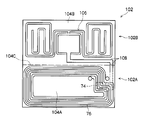
- the base sheet 104 constituting the composite communication device 102 has a first base portion 104A and a second base portion 104B.
- the first base portion 104A is formed in the same manner as the first base portion 72A and is provided with an IC chip 74 and an antenna 76, and constitutes the memory board portion 102A.
- the second base portion 104B is formed in a continuous rectangular shape with the same length as the first base portion 104A above the memory board portion 102A.
- a boundary portion between the first base portion 104A and the second base portion 104B is a bent portion 104C. Accordingly, a difference in built-in posture between the first base portion 104A inclined with respect to the rear wall 12B and the bottom plate 16A and the second base portion 104B along the rear wall 12B is allowed (set).
- the UHF band RFID tag unit 102B is configured by providing a tag antenna 106 as a second antenna on the second base unit 104B.
- the tag antenna 106 and the IC chip 74 are electrically connected by the wiring part 108.
- the tag antenna 106 is configured as a kind of so-called dipole antenna formed symmetrically (line symmetric) with respect to a connection portion with the IC chip 74 (wiring portion 108).
- the UHF band RFID tag portion 102B is also accommodated in the upper case 14, as shown in FIG. That is, the main part of the UHF band RFID tag part 102B constituting the composite communication device 102 protrudes upward from the outer peripheral wall 16B and is disposed along the rear wall 12B in the upper case 14. Thereby, in the recording tape cartridge 100, the formation area of the tag antenna 106 is ensured. In this embodiment, a gap is formed between the holding rib 86 and the outer peripheral wall 14B constituting the rear wall 12B, and the UHF band RFID tag portion 102B enters the gap.
- the other configuration of the recording tape cartridge 100 according to the third embodiment is the same as the corresponding configuration of the recording tape cartridge 10 including a portion not shown.
- the recording tape cartridge 100 according to the third embodiment is basically the same as the recording tape cartridge 10 according to the first embodiment except for the effect that the tag antenna 78 can be enlarged. The effect of can be obtained. Further, in the recording tape cartridge 100, since the composite communication device 102 is built in the corner portion 12BR as a whole, there is no possibility of interference with the reel 20 or the like. For this reason, the composite communication device 102 has fewer restrictions on dimensional accuracy than the composite communication device 70 having the UHF band RFID tag portion 70B exposed in the reel space 34.
- FIG. 16 is a perspective view corresponding to FIG. 1 showing a main part of a recording tape cartridge 110 according to the fourth embodiment of the present invention.
- the recording tape cartridge 110 is different from the recording tape cartridge 100 according to the third embodiment in that a composite communication device 112 is provided instead of the composite communication device 102.
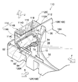
- the composite communication device 112 has a UHF band RFID tag part 112B as a second communication part, a part of which is arranged along the top plate 14A.
- the composite communication device 112 includes a memory board part 112A as a first communication part configured in the same manner as the memory board part 102A (memory board part 70A), and a UHF band RFID tag part 112B as main parts. .
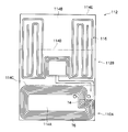
- the base sheet 114 constituting the composite communication device 112 has a first base portion 114A and a second base portion 114B.
- the first base portion 114A is formed in the same manner as the first base portion 104A (first base portion 72A) and is provided with an IC chip 74 and an antenna 76, and constitutes a memory board portion 112A.
- the second base portion 114B is continuous with the same length as the first base portion 114A above the memory board portion 112A, and the intermediate portion in the vertical direction is bent. That is, the base sheet 114 includes a bent portion 114C that forms a boundary portion between the first base portion 114A and the second base portion 114B, and a bent portion 114D that is formed at an intermediate portion of the second base portion 114B. As shown in FIG.
- the base sheet 114 includes a first base portion 114A that is inclined with respect to the rear wall 12B and the bottom plate 16A by a bent portion 114C, and a second base portion 114B that is “L” -shaped in a side view along the rear wall 12B and the top plate 14A. The difference in the built-in posture is allowed (set).
- the UHF band RFID tag part 112B is configured by providing a tag antenna 116 as a second antenna on the second base part 114B.
- the tag antenna 116 and the IC chip 74 are electrically connected by a wiring part 118.
- the tag antenna 116 is configured as a kind of so-called dipole antenna formed symmetrically (line symmetric) with respect to the connection portion with the IC chip 74 (wiring portion 118).
- the main part of the UHF band RFID tag part 112B protrudes upward from the outer peripheral wall 16B and extends along the rear wall 12B and the top plate 14A in the upper case 14.
- the lower portion of the base sheet 114 with respect to the bent portion 114D is disposed along the rear wall 12B (the outer peripheral wall 14B constituting the portion), and the portion on the free end 114E side with respect to the bent portion 114D. Is arranged along the top plate 14A.
- the portion between the bent portion 114D and the free end 114E arranged along the top plate 14A in the second base portion 114B faces (separates) the top plate 14A at a predetermined interval.
- a pressing rib 115 protruding low from the top plate 14 ⁇ / b> A instead of the pressing rib 86 is configured to sandwich and hold the composite communication device 112 with the inclined rib 82.
- the other configuration of the recording tape cartridge 110 according to the fourth embodiment is the same as the corresponding configuration of the recording tape cartridge 100 including a portion not shown.
- the recording tape cartridge 110 according to the fourth embodiment can basically obtain the same effect by the same operation as that of the recording tape cartridge 100 according to the third embodiment. Further, in the recording tape cartridge 110, since the second base portion 114B includes a portion disposed along the top plate 14A, a large tag antenna 116 can be provided as compared with the tag antenna 106. .
- the portion between the bent portion 114D arranged along the top plate 14A and the free end 114E in the second base portion 114B is opposed to the top plate 14A in a non-contact manner.
- the present invention is not limited to this, and the portion may be in contact with the top plate 14A.
- FIG. 20 is an exploded perspective view showing the composite communication device 70 and the reinforcing member 122 that constitute the recording tape cartridge 120 according to the fifth embodiment of the present invention.
- FIG. 21 is a perspective view showing a combined state of the composite communication device 70 and the reinforcing member 122 constituting the recording tape cartridge 120.
- the recording tape cartridge 120 is different from the recording tape cartridge 10 according to the first embodiment in that the recording tape cartridge 120 includes a reinforcing member 122 that holds the composite communication device 70 in a built-in posture in the case 12. .
- the recording tape cartridge 120 is formed in substantially the same shape as the base sheet 72 after the connecting portion 72D is deformed by, for example, injection molding of resin goods, etc., and has higher rigidity than the base sheet 72.
- the reinforcing member 122 is made of a material having a higher elastic modulus than that of the constituent material of the base sheet 72, is formed to be thicker than the base sheet 72, or a combination thereof.
- the base sheet 72 is configured with higher rigidity.
- each of the first base portion 72A and the second base portion 72B is joined to the reinforcing member 122 by joining means such as adhesion or double-sided tape.
- the recording tape cartridge 120 is configured such that the composite communication device 70 is held in the built-in posture in the case 12 before being built in the case 12.
- Other configurations of the recording tape cartridge 120 according to the fifth embodiment are the same as the corresponding configurations of the recording tape cartridge 10 including a portion not shown.
- the recording tape cartridge 120 according to the fifth embodiment can basically obtain the same effect by the same operation as that of the recording tape cartridge 10 according to the first embodiment.
- the composite communication device 70 is held (reinforced) by the reinforcing member 122, it is easy to incorporate the composite communication device 70 into the case 12. Further, since the posture of the composite communication device 70 is held by the reinforcing member 122, the posture of the composite communication device 70 is held in the case 12 without depending on the rear wall 12B of the case 12, the inclined rib 82, or the like. It can be configured.
- the composite communication device 70 is held by the reinforcing member 122 is shown, but the present invention is not limited to this.
- the composite communication devices 92, 102, and 112 may be held by reinforcing members having shapes corresponding to these base sheets 94, 104, and 114.
- the reinforcing member 122 and the like have a shape corresponding to the composite communication device 70 and the like has been described, but the present invention is not limited to this.
- a portion of the reinforcing member 122 that protrudes from the base sheet 72 may be engaged with the case 12 and supported by the case 12.
- FIG. 23 is a perspective view showing the appearance of a recording tape cartridge 130 according to the fifth embodiment of the present invention.
- FIG. 22 shows an exploded perspective view of the recording tape cartridge 100 as viewed from above. In FIG. 22, the lock mechanism 48 is not shown.
- the recording tape cartridge 130 includes a case 132.
- the case 132 includes an upper case 134 in which an outer peripheral wall 134B is erected downward from a peripheral edge of a substantially rectangular top plate 134A, and a lower case in which an outer peripheral wall 138B is erected upward from a peripheral edge of a substantially rectangular bottom plate 138A. It is configured by joining with the case 138.
- An opening 136 is formed at the right front corner of the case 132 so as to face both the right side and the front side.
- the pin receiving recess 24 is provided facing the opening 136.
- the opening 136 is opened and closed by a door 140 that is curved in an arc shape in plan view.
- the door 140 has a curvature equivalent to the curvature of the door 140 and is guided by the guide grooves 142 formed on the top plate 134A and the bottom plate 138A, and moves without protruding on the movement trajectory along the arc shape.
- 136 is configured to open and close. Further, in the case 132, the screw bosses 15 are arranged on both sides of the opening 136.
- the case 132 includes a reel area rib 144 that partitions the reel space 34 from the rear space.
- the distance between the reel area rib 144 and the rear wall 132B of the case 132 is set wide at the rear portion of the case 132.
- the composite communication device 145 constituting the recording tape cartridge 130 includes a memory board unit 145A as a first communication unit configured similarly to the memory board unit 102A (memory board unit 70A), and a second communication unit.
- the UHF band RFID tag part 145B is configured as a main part.
- the base sheet 146 constituting the composite communication device 145 has a first base portion 146A and a second base portion 146B.
- the first base portion 146A is formed in the same manner as the first base portion 114A (first base portion 72A) and is provided with an IC chip 74 and an antenna 76 (not shown), and constitutes a memory board portion 145A. Yes.
- the second base portion 146B includes an upper base portion 146BU that is continuous with the same length as the first base portion 146A from the upper end of the memory board portion 145A, and a length that is the same as the first base portion 146A from the front end of the memory board portion 145A.
- the lower base portion 146BL is continuous.
- the upper base portion 146BU has the same size and shape as the second base portion 104B, is disposed along the rear wall 132B, and is bent between the rear wall 132B and the first base portion 146A inclined with respect to the bottom plate 138A.
- a portion 146C is formed.
- the lower base portion 146BL is disposed along the bottom plate 138A, and a bent portion 146D is formed between the rear wall 132B and the first base portion 146A inclined with respect to the bottom plate 138A.
- the UHF band RFID tag unit 145B is configured by providing a tag antenna 148 as a second antenna on the second base unit 146B.
- the tag antenna 148 and the IC chip 74 are electrically connected by a wiring unit (not shown).
- the tag antenna 148 is configured as a kind of so-called dipole antenna formed symmetrically (line symmetric) with respect to the connection portion with the IC chip 74.
- the tag antenna 148 may have a configuration in which one side of the dipole antenna is provided on the upper base portion 146BU and the other side of the dipole antenna is provided on the lower base portion 146BL.
- the composite communication device 145 described above is held with respect to the case 132 by sandwiching the memory board portion 145A (first base portion 146A) between the inclined rib 82 and the holding rib 86 (not shown).
- Other configurations of the recording tape cartridge 130 according to the sixth embodiment are the same as the corresponding configurations of the recording tape cartridge 100 including a portion not shown.
- the recording tape cartridge 130 according to the sixth embodiment can basically obtain the same effect by the same operation as that of the recording tape cartridge 100 according to the third embodiment.
- the tag antenna 148 that is larger than the tag antenna 106 can be provided.
- the composite communication device 150 may include a base sheet 152 in which the first base portion 152A and the second base portion 152B are separately formed.
- the terminal 154 for electrically connecting to the part that performs the function of the UHF band RFID tag unit 150B as the second communication unit in the IC chip 74 includes the first communication unit.
- a terminal 156 at the end of the wiring portion 80 electrically connected to the center portion of the tag antenna 78 is provided on the second base portion 152B.
- a slit 152C similar to the slit 72E is formed in the second base portion 152B as necessary.
- the composite communication device 150 is connected (mechanically) so that the first base portion 152A and the second base portion 152B can be integrally handled before being incorporated in the case 12, and the terminals 154 and 156 are connected to each other. Are electrically connected through a wiring member or the like (not shown).
- the mechanical connection between the first base portion 152A and the second base portion 152B may be performed by directly joining them, or may be performed by indirectly joining them via the reinforcing member 122 or the like. good.
- the present invention is not limited to the configuration of each of the above-described embodiments, and can of course be implemented with various modifications. Therefore, for example, the second base portion 72B constituting the memory board portion may be arranged along the rear wall 12B over the substantially entire height of the rear wall 12B between the left and right corner portions 12BR and 12BL. good.
- the present invention is not limited to this.
- a configuration may be adopted in which an IC chip independent of the memory board part and the UHF band RFID tag part is provided in the first base part.
Landscapes
- Slot Machines And Peripheral Devices (AREA)
Abstract
ケース内に通信方式の異なる2つの通信部を良好に内蔵することができる記録テープカートリッジを得る。 記録テープカートリッジ(10)は、記録テープTが巻き回されたリール(20)と、リール(20)が収容されたケース(12)と、ケース(12)内に設けられた複合通信デバイス(70)を備えている。複合通信デバイス(70)のメモリボード部(70A)は、ベースシート(72)の第1ベース部(72A)に設けられたICチップ(74)及びアンテナ(76)を有して構成されており、UHF帯RFIDタグ部(70B)は、ベースシート(72)の第1ベース部(72A)に設けられたICチップ(74)、及び第2ベース部(72B)に設けられたタグアンテナ(78)とを有して構成されている。
Description
本発明は、電磁誘導方式で外部と通信する第1の通信部と、電波方式で外部と通信する第2の通信部とが内蔵された記録テープカートリッジに関する。
カートリッジケースの後壁部の内面に沿って、UHF帯で動作するRFIDタグを配置した磁気テープカートリッジが知られている(例えば、特開2007-257744号公報参照)。また、通信周波数帯域の異なる2つのアンテナ、2つのICチップを備えたICタグが知られている(例えば、特開2007-324638号公報参照)。この構成において、一方のアンテナは、他方のアンテナの一部に直交するように厚み方向に重ね合わされて配置され、2つのアンテナの干渉が抑制されるようになっている。
しかしながら、通信方式の異なる2つの通信部を、リールを回転可能に収容するケースに内蔵するには制約があり、この点に改善の余地がある。
本発明は、ケース内に通信方式の異なる2つの通信部を良好に内蔵することができる記録テープカートリッジを得ることが目的である。
本発明の第1の態様に係る記録テープカートリッジは、記録テープが巻き回されたリールと、前記リールが収容されたケースと、前記ケース内に設けられた第1の基部と、該第1の基部に設けられた第1の素子部と、前記第1の基部に設けられた第1のアンテナとを有し、電磁誘導方式で前記ケースの外部と通信する第1の通信部と、前記第1の基部に設けられた第2の素子部と、前記第1の基部と一体として取り扱い可能に該第1の基部に連結された第2の基部と、該第2の基部に設けられた第2のアンテナとを有し、電波方式で前記ケースの外部と通信する第2の通信部と、を備えている。
この態様によれば、ケースに内蔵された第1の通信部は、電磁誘導方式でケースの外部と通信し、ケースに内蔵された第2の通信部は、電波方式でケースの外部と通信を行う。
ここで、第2の通信部を構成する第2の基部が第1の通信部を構成する第1の基部と一体として取り扱い可能に構成されている。このため、第1の通信部をケースに対し内蔵(位置決め)すると、第2の通信部がケースに対し所要の位置に配置される。また、第2の通信部を構成する第2の素子部(通信回路部)が第1の基部に設けられているので、第2の通信部は配置に対する制約が少ない。すなわち、素子部は、リール等のケースに対する可動体との干渉からの保護のために配置に制約がある。しかしながら、本記録テープカートリッジにおける第2の通信部は、素子部が第1の基部に設けられているので、ケースに対する可動体との干渉から第2の素子部を保護するために配置上の制約を受けることがない。したがって、第2の通信部を構成する第2の基部及び第2のアンテナは、例えば、ケース内におけるスペース効率上の又は通信上の適所に配置することができる。
このように、上記態様の記録テープカートリッジでは、ケース内に通信方式の異なる2つの通信部を良好に内蔵することができる。
上記態様の記録テープカートリッジにおいて、前記第2の通信部は、前記第1の通信部よりも通信可能距離が長く設定されている。
この態様によれば、第2の通信部は相対的に通信距離が長いために第2のアンテナ部の大型化が要求されるが、上記の通り第2のアンテナのケース内での配置自由度が高いので、該第2のアンテナを大型化しやすい。
上記態様の記録テープカートリッジにおいて、前記第2の素子部は、前記第1の素子部と一体に構成されている。
この態様によれば、第1の基部に設けられた第1、第2の素子を一体に構成することができるので、2つの機能の素子を別体として有する構成と比較して、構造が簡素化される。
上記態様の記録テープカートリッジにおいて、前記第2の基部は、前記第1の基部と一体に構成されている。
この態様によれば、第1、第2の基部が一体に形成されているので、各素子部とアンテナ部との電気的接続構造を、併せて一体に構成することができる。
上記態様の記録テープカートリッジにおいて、前記第1の基部は、前記ケースの周壁及び底板の双方を向くように該周壁及び底板に対し傾斜して配置されており、前記第2の基部は、前記ケースの周壁、底板、天板、及び前記周壁の内側で前記底板又は天板から立設された内壁の少なくとも1つに沿って配置されている。
この態様によれば、第1の基部すなわち第1のアンテナはケース周壁及び底板に対し傾斜されており、第2の基部すなわち第2のアンテナはケースの周壁、底板、天板、内壁の何れかに沿って配置されている。このように、第1、第2のアンテナは、要求される通信方向に応じた配置とされる。
上記態様の記録テープカートリッジにおいて、前記第1の基部と第2の基部とは、一端側が開口されたスリットの他端側で互いに連結されており、該連結部分は、可撓性を有する変形許容部とされている。
この態様によれば、第1、第2基部は、スリット他端側の切り残し部分である可撓性の変形許容部にて連結されている。このため、この変形許容部の変形によって、ケース周壁及び底板に対し傾斜された第1の基部と、ケースの立壁である周壁、底板、天板、内壁の何れかに沿って配置された第2の基部とのケースに対する内蔵姿勢(向き)を異ならせることが許容される。
上記態様の記録テープカートリッジにおいて、前記第1の基部は、前記ケースの周壁におけるドライブ装置への装填方向の先頭側とは反対側を向く背壁及び該ケースの底板の双方を向くように、該ケース内の角隅部で前記背壁及び底板に対し傾斜して配置されており、前記第2の基部は、前記第1の基部から、前記背壁に沿って、前記第1の基部が配置された前記ケースの角隅部と反対側に位置する角隅部に向けて延在されている。
この態様によれば、第1の通信部は、ケースにおける背壁側の一方の角隅部に配置されており、該一方の角隅部から他方の角隅部に向けて第2の基部が背壁に沿って延在されている。リールとの間隔が相対的に広い角隅部では第1の基部が上記の通り傾斜配置され、リールとの間隔が相対的に狭い角隅部間では第2の基部が立壁である背壁に沿って配置される。
上記態様の記録テープカートリッジにおいて、前記ケースには、前記リールを径方向の外側から覆う内壁が該ケースの底板及び天板から立設されており、前記第1の基部は、前記ケースの周壁におけるドライブ装置への装填方向の先頭側とは反対側を向く背壁及び該ケースの底板の双方を向くように、該ケース内の角隅部で前記背壁及び底板に対し傾斜して配置されており、前記第2の基部は、前記第1の基部が配置された前記ケースの角隅部と前記リールの設置空間とを隔てる前記内壁に沿って延在されている。
この態様によれば、第1の通信部は、ケースにおける背壁側の一方の角隅部に配置されており、該一方の角隅部をリールの配置領域と隔てる内壁に沿って第2の基部が延在されている。リールとの間隔が相対的に広い角隅部において第1の基部が上記の通り傾斜配置され、この角隅部をリールの配置空間と隔てる内壁に沿って第2の基部が配置される。すなわち、第1の基部及び第2の基部が共通の角隅部に配置される。
上記態様の記録テープカートリッジにおいて、前記第1の基部は、前記ケースの周壁におけるドライブ装置への装填方向の先頭側とは反対側を向く背壁及び該ケースの底板の双方を向くように、該ケース内の角隅部で前記背壁及び底板に対し傾斜して配置されており、前記第2の基部は、前記第1の基部から、前記ケースにおける前記第1の基部が配置された前記角隅部を構成する前記背壁、底板、及び天板の少なくとも何れかに沿って延在されている。
この態様によれば、第1の通信部は、ケースにおける背壁側の一方の角隅部に上記の通り傾斜配置されており、該一方の角隅部を構成する(規定する)背壁、底板、天壁の少なくとも何れかに沿って第2の基部が延在されている。リールとの間隔が相対的に広い角隅部において、第1の基部及び第2の基部が共に配置される。
上記態様の記録テープカートリッジにおいて、前記第1の基材及び第2の基材を前記ケースに内蔵される姿勢に保持する補強部材をさらに備えている。
この態様によれば、補強部材によって第1、第2の通信部がケースへの内蔵姿勢に保持される。これにより、予めケースへの内蔵姿勢とされた第1、第2の通信部を、容易にケースに内蔵することができる。また、これら第1、第2の通信部は、ケースの立壁に頼ることなくケース内での姿勢が保持される構成とすることが可能である。
上記態様の記録テープカートリッジにおいて、前記第2の基部には、前記ケースにおける天板又は底板から立設された内壁を跨ぐスリットが形成されており、前記内壁には、前記第2の基部における前記スリットの切り残し部分を入り込ませるスリットが形成されている。
この態様によれば、ケースの内壁と第2の基部とが互いのスリット切り残し部分を相手方スリットに入り込ませて、第2の通信部がケースに内蔵されている。これにより、第2の基部は、内壁を跨いで設置されることとなり、第2のアンテナを大きくすることができる。また、第2の基部がケースに対し位置決めされる。
以上説明したように本発明に係る記録テープカートリッジは、ケース内に通信方式の異なる2つの通信部を良好に内蔵することができるという優れた効果を有する。
本発明の第1の実施形態に係る記録テープカートリッジ10について、図1~図9に基づいて説明する。先ず、記録テープカートリッジ10の全体構成を説明し、次いで、記録テープカートリッジ10に内蔵される複合通信デバイス70、及び複合通信デバイス70の内蔵構造について説明することとする。なお、以下の説明では、便宜上、各図に適宜示す矢印U方向を上方向、矢印F方向を前方向(ドライブ装置への装填方向)、矢印R方向を右方向、矢印L方向を左方向とするが、これらの方向は記録テープカートリッジ10の姿勢を限定するものではない。
図3には、記録テープカートリッジ10の外観が斜視図にて示されている。また、図4には、記録テープカートリッジ10の上方から見た分解斜視図が示されており、図5には、記録テープカートリッジ10の下方から見た分解斜視図が示されている。これらの図に示される如く、記録テープカートリッジ10は、ケース12を備えている。ケース12は、下向きに開口する樹脂製の上ケース14と上向きに開口する樹脂製の下ケース16とを、互いの開口端を突き合わせて接合することで構成されている。この実施形態では、ケース12は、平面視で略矩形状(正方形状)を成すと共に上下方向に薄い扁平ケースとして構成されている。
具体的には、上ケース14は、平面視で略矩形状の天板14Aの周縁部から外周壁14Bが下向きに立設されて成る。下ケース16は、平面視で略矩形状の底板16Aの周縁部から外周壁16Bが上向きに立設されて成る。ケース12は、外周壁14Bと外周壁16Bとの開口端が突き当てられた状態で上ケース14と下ケース16とが接合されることで構成されている。この実施形態では、上ケース14の天板14A、下ケース16の底板16Aから突出されたビスボス15同士を突き当て、下側のビスボス15内に頭部が収容されたビス(図示省略)のねじ部が上側のビスボス15にねじ込まれる。これにより、上ケース14と下ケース16とが接合されている。
このケース12内には、記録テープとしての磁気テープTが巻き回された単一のリール20が回転可能に収容されている。リール20に巻き回された磁気テープTは、図示しないドライブ装置内において、ケース12の右側壁12Rにおける前端側に形成された開口18を通じてケース12の外側に引き出されるようになっている。この開口18を通じてケース12から引き出された磁気テープTに対して情報の読み書きが行われるようになっている。磁気テープTの先端には、ドライブ装置により磁気テープTを引き出す際に操作(保持)されるリーダ部材としてのリーダピン22が取り付けられている。
リーダピン22は、その両端に形成されると共に磁気テープTの幅方向端部から突出されたフランジ22Aが、ケース12における開口18に臨む位置に設けられたピン受け凹部24に入り込まされることで、該ケース12に対し所定の位置で保持されるようになっている。また、ケース12には、フランジ22Aをピン受け凹部24の凹壁に押し付けることで、ケース12に対するリーダピン22の姿勢を保持するためのスプリング26が設けられている。このリーダピン22は、フランジ22Aと磁気テープTとの間の細軸部分がドライブ装置の引き出し部材に引っ掛けられて、磁気テープTと共にケース12から引き出されるようになっている。
さらに、ケース12の開口18は、開閉部材としてのドア28によって開閉されるようになっている。ドア28は、外周壁14Bと外周壁16Bとで成る右側壁12Rに沿って形成されたガイド溝25にガイドされつつ前後方向にスライドすることで、開口18を開閉する構成とされている。ドア28は、ドアスプリング30によって、開口18を閉じる方向に付勢されている。
またさらに、ケース12には、リール20を径方向外側(外周側)から覆うにように設けられた立壁部である内壁としてのリールエリアリブ32が立設されている。リールエリアリブ32は、天板14A、底板16Aのそれぞれから立設された半体同士が接合されて構成され、リール20が配置されるリール空間34を囲む構成とされている。この実施形態では、リールエリアリブ32は、周方向に部分的に複数立設されており、それぞれの周方向端部は内壁としての連結壁36を介して外周壁14B、外周壁16Bに連結されている。なお、開口18の近傍に位置するリールエリアリブ32の周方向端部には、ガイド溝25を形成するために連結壁36は連結されず、強度確保のためにビスボス15が一体化されている。
また、ケース12の底板16Aの略中央部には、リール20の軸心部を成すリールハブ35の底部35Aに設けられたリールギヤ38及び磁性金属製のリールプレート40を露出させるためのリール開口42が形成されている。ドライブ装置の図示しない回転シャフトは、マグネットによってリールプレート40を吸着保持しつつ駆動ギヤをリールギヤ38に噛み合わせて、リール20を回転駆動するようになっている。
リール20は、リールハブ35の外周面に巻き回された磁気テープTの幅方向のずれを規制する上下一対のフランジ44、46を有する。すなわち、フランジ44、46間に磁気テープTが巻き回されている。さらに、リールハブ35の円筒部内には、ケース12に対するリール20の回転をロック、ロック解除するためのロック機構48が設けられている。
ロック機構48は、リールハブ35の底部35Aの上面側に設けられた上向きの係合ギヤ50と、係合ギヤ50に噛み合い可能な下向きの制動ギヤ52Aを有する制動部材52と、制動部材52のケース12に対する回転を禁止する回転止め部55と、制動ギヤ52Aが係合ギヤ50に噛み合うように制動部材52を下向きに付勢するロックスプリング54と、ロックスプリング54の付勢力に抗して制動部材52を上方に押し上げるための解除操作部材56とを主要部として構成されている。
回転止め部55は、天板14Aから突出された十字リブ58を制動部材52の十字溝60に上下方向に相対変位可能に挿入することで構成されている。解除操作部材56は、底部35Aと制動部材52との間に配置され、上方に移動することで制動部材52を上側に移動させて制動ギヤ52Aの係合ギヤ50への噛み合いすなわちリール20の回転ロック状態を解除する構成とされている。
この実施形態では、解除操作部材56は、平面視で略三角形状に形成された本体56Aの各頂部から垂下された脚部56Bが底部35Aの貫通孔35Bを貫通している。脚部56Bは、リールギヤ38の歯間に突出されており、該リールギヤ38に噛み合う回転シャフトの駆動ギヤによって上方に押圧、移動されるようになっている。すなわち、ロック機構48は、リールギヤ38とドライブ装置側の駆動ギヤとの噛み合いに伴ってリール20のケース12に対する回転ロック状態が解除される構成とされている。解除操作部材56は、リール20と一体に回転し、その中央部に設けられた突起56Cにおいて、ケース12に対し回り止めされた制動部材52の球面状の突起52Bと低摩擦で摺接するようになっている。
また、記録テープカートリッジ10は、磁気テープTへの情報の書き込みを禁止するためのライトプロテクト部62を備えている。ライトプロテクト部62は、誤消去防止プラグ64が、ユーザの操作によって、磁気テープTへの情報の書き込みを許容する許容位置と、磁気テープTへの情報の書き込みを禁止する禁止位置との間で移動可能に設けられて構成されている。この実施形態では、誤消去防止プラグ64は、ケース12の後左の角隅部12BLで、後壁12Bに沿って移動することで、許容位置と禁止位置とをとり得る構成とされている。誤消去防止プラグ64は、下ケース16と上ケース14とに跨って配置されており、下ケース16内で後壁12Bと略平行に設けられた下ガイド壁68と、上ケース14内で後壁12Bと略平行に設けられた上ガイド壁66とによってガイドされるようになっている。
(複合通信デバイスの構成)
以上説明した記録テープカートリッジ10は、ケース12に内蔵された複合通信デバイス70を備えている。図7~図9に示される如く、複合通信デバイス70は、電磁誘導方式の短波(HF)でケース12の外部と非接触通信を行う第1の通信部としてのメモリボード部70Aと、UHF帯の電波方式でケース12の外部と無線通信を行う第2の通信部としてのUHF帯RFID(Radio Frequency IDentificationタグの略で、RFタグやICタグともいう)タグ部70Bとを主要部として構成されている。
以上説明した記録テープカートリッジ10は、ケース12に内蔵された複合通信デバイス70を備えている。図7~図9に示される如く、複合通信デバイス70は、電磁誘導方式の短波(HF)でケース12の外部と非接触通信を行う第1の通信部としてのメモリボード部70Aと、UHF帯の電波方式でケース12の外部と無線通信を行う第2の通信部としてのUHF帯RFID(Radio Frequency IDentificationタグの略で、RFタグやICタグともいう)タグ部70Bとを主要部として構成されている。
メモリボード部70Aは、例えば、記録テープカートリッジ10の個体識別情報、製造情報、磁気テープTの記録容量や記録形式等の個体ごとの各種情報が、後述するICチップ74に記憶されている。UHF帯RFIDタグ部70Bは、例えば、従来は記録テープカートリッジ10に貼付されたバーコードラベル等で表されていた情報、保管時及びオートローダによる搬送使用時のカートリッジ個体一元管理(磁気テープTへの記録内容との関係を考慮した管理)のための情報が、後述するICチップ74に読み書きされるようになっている。
この実施形態に係る複合通信デバイス70は、メモリボード部70Aの通信距離は10mm~数10mmとされており、UHF帯RFIDタグ部70Bの通信距離は略1m程度の範囲内に設定されている。すなわち、UHF帯RFIDタグ部70Bの通信距離はメモリボード部70Aの通信距離よりも長く設定されている。一方、メモリボード部70Aは、UHF帯RFIDタグ部70Bに対し大きな記録容量を有する。この実施形態では、UHF帯RFIDタグ部70Bが96bit~120bit(12B~15B)の容量を有するのに対し、メモリボード部70Aは4KB~8KBの記録容量を有する構成とされている。
この複合通信デバイス70は、基部であるベースシート72を備えている。ベースシート72は、フィルム状に形成されており、可撓性を有している。そして、図7~図9に示される如く、ベースシート72は、メモリボード部70Aを構成する第1の基部としての第1ベース部72Aと、UHF帯RFIDタグ部70Bを構成する第2の基部としての第2ベース部72Bとを有する。
ベースシート72は、例えばポリエチレンテレフタレート(PET)等の樹脂材にて構成されており、この実施形態では、それぞれ矩形状を成す第1ベース部72Aと第2ベース部72Bとが一体に形成されている。上記の通りメモリボード部70Aに対し長い通信距離が要求されているUHF帯RFIDタグ部70Bを構成する第2ベース部72Bは、後述するタグアンテナ78の大型化を考慮して、第1ベース部72Aに対し長手寸法が長く設定されている。
また、第1ベース部72Aと第2ベース部72Bとの間には、下向きに開口するスリット72Cが形成されている。スリット72Cに対する開口側とは反対側の部分は、第1ベース部72Aと第2ベース部72Bとを連結する切り残し部としての連結部72Dとされている。上記の通り可撓性を有すベースシート72は、連結部72Dの変形によって第1ベース部72Aと第2ベース部72Bとが後述する如く異なる姿勢(図8参照)をとり得る構成とされている。したがって、連結部72Dは本発明の変形許容部に相当する。
図9に示される如く、メモリボード部70Aは、第1ベース部72Aに第1の素子部としてのICチップ74及び第1のアンテナとしてのアンテナ76を形成して構成されている。ICチップ74は、第1ベース部72Aにおける連結部72D近傍の角隅部に配置されている。この実施形態では、ICチップ74は、第1ベース部72Aへの設置状態で図示しない保護層にて被覆されている。アンテナ76は、アルミニウムや銅などの導電材より成るループアンテナとされており、第1ベース部72Aの周縁部に沿って複数周に亘り形成されている。アンテナ76の総延長は、通信周波数(この実施形態では、13.56MHz)に応じて決められている。
UHF帯RFIDタグ部70Bは、第1ベース部72Aに設けられた第2の素子部としてのICチップを備えて構成されている。この実施形態では、UHF帯RFIDタグ部70Bを構成するICチップは、ICチップ74に一体化されている。換言すれば、ICチップ74は、メモリボード部70Aの通信機能(記憶等を含む)を果たす第1回路部と、この第1回路部とは独立してUHF帯RFIDタグ部70Bの通信機能(記憶等を含む)を果たす第2回路部とが、共通の半導体素子として構成されたものとして捉えることができる。
そして、UHF帯RFIDタグ部70Bは、第2ベース部72Bに形成されると共にICチップ74(の第2回路部)に電気的に接続された第2のアンテナとしてのタグアンテナ78を備えている。タグアンテナ78は、アルミニウムや銅などの導電材より成り、第2ベース部72Bの長手方向中央部に対し略対称に形成されている。ICチップ74とタグアンテナ78の中央部とは、配線部80によって電気的に接続されている。この実施形態に係るタグアンテナ78は、配線部80すなわちICチップ74との接続部に対し対称(線対称)に形成された所謂ダイポールアンテナの一種として構成されている。
タグアンテナ78における両端には、他の部分よりも幅広とされた略長方形状の放射部78Aが形成されている。タグアンテナ78における放射部78A以外の部分は、給電部78Bとされており、この給電部78Bが複数回折り返されることで、第2ベース部72Bの寸法内でタグアンテナ78の総延長を確保している。このタグアンテナ78の総延長は、通信周波数(この実施形態では、860~960MHzの範囲内の特定周波数)に応じて決められている。なお、配線部80は、アンテナとして機能しないように電波に対しシールドされた構造とされている。
(複合通信デバイスのケースへの内蔵構造)
以上説明した複合通信デバイス70は、図1及び図2に示される如く、ケース12の背面側に内蔵されている。この実施形態では、複合通信デバイス70は、上記の姿勢で、ケース12構成する下ケース16内に、外周壁16Bの上端よりも突出しないように配置されている。より具体的には、メモリボード部70Aは、ケース12における右後(開口18の後方)の角隅部12BR内に配置されている。角隅部12BRは、主に後壁12Bと右側壁12Rとリールエリアリブ32とで囲まれた、リール空間34の外側の空間として捉えることができる。
以上説明した複合通信デバイス70は、図1及び図2に示される如く、ケース12の背面側に内蔵されている。この実施形態では、複合通信デバイス70は、上記の姿勢で、ケース12構成する下ケース16内に、外周壁16Bの上端よりも突出しないように配置されている。より具体的には、メモリボード部70Aは、ケース12における右後(開口18の後方)の角隅部12BR内に配置されている。角隅部12BRは、主に後壁12Bと右側壁12Rとリールエリアリブ32とで囲まれた、リール空間34の外側の空間として捉えることができる。
また、UHF帯RFIDタグ部70Bは、角隅部12BRからケース12における左後の角隅部12BLに向けて、背壁としての後壁12Bに沿って延在されている。角隅部12BLは、主に後壁12Bと左側壁12Lとリールエリアリブ32とで囲まれた、リール空間34の外側の空間として捉えることができる。この実施形態では、UHF帯RFIDタグ部70Bを構成する第2ベース部72B(タグアンテナ78)は、その長手方向の一端が角隅部12BRに配置されると共に、その長手方向の他端が角隅部12BLに配置されている。
このため、第2ベース部72Bには、下向きに開口して下ケース16の連結壁36を跨ぐスリット72Eが形成されている。また、連結壁36における後壁12Bとの境界部近傍には、上向きに開口してスリット72E上方の切り残し部72Fが入り込まされるスリット36Aが形成されている。
さらに、メモリボード部70Aは、後壁12B及び底板16Aの双方を向くように該後壁12B及び底板16Aのそれぞれに対し傾斜して配置されている。具体的には、図7に示される如く平坦状に形成された複合通信デバイス70は、連結部72Dをねじり変形することで、図8に示される如くUHF帯RFIDタグ部70B(第2ベース部72B)に対しメモリボード部70A(第1ベース部72A)が傾斜された姿勢、すなわちケース12への内蔵姿勢とされている。
一方、図2に示される如く、下ケース16は、角隅部12BRを構成する後壁12B(外周壁16B)及び底板16Aに跨るように形成された傾斜リブ82を有しており、メモリボード部70Aは、傾斜リブ82上に配置されることで、上記の通り傾斜配置されている。図6に示される如く、傾斜リブ82の前方では、メモリボード部70Aの前下端に係合して該メモリボード部70Aの前方への移動を規制するストッパリブ84が底板16Aから立設されている。
また、上ケース14は、傾斜リブ82との間でメモリボード部70Aを挟み込んで保持するように後壁12B(外周壁16B)及び天板14Aに跨って形成された押さえリブ86を有する。これら傾斜リブ82、ストッパリブ84、押さえリブ86によって、メモリボード部70Aのケース12に対する位置(姿勢)が決まると共に該姿勢が維持される構成である。
一方、UHF帯RFIDタグ部70Bは、上記の通り、スリット72Eに連結壁36を入り込ませると共に、切り残し部72Fをスリット36Aに入り込ませることで、後壁12Bに沿って配置されたケース12に対する姿勢が決まり、該姿勢が維持されるようになっている。第2ベース部72Bは、後壁12Bに接触又はごく近接して配置されている。この第2ベース部72Bは、例えば接着剤や両面テープ等にて全体的に又は部分的に後壁12Bに接合されても良い。
次に、本実施形態の作用について説明する。
上記構成の記録テープカートリッジ10では、磁気テープTに情報を書き込む際、又は磁気テープTに書き込まれた情報を読み取る場合には、ドライブ装置に装填される。この装填動作に伴って開口18が開放されると共に、リール20のリールギヤ38に回転シャフトの駆動ギヤが噛み合わされ、リール20の回転ロックが解除される。ドライブ装置は、リーダピン22を先頭に磁気テープTを引き出して該リーダピン22をドライブ装置側のリールにセットすると、該リールとリール20と同期して回転駆動しながら、テープ経路中に設けられたヘッドによって磁気テープTに対する情報の書き込み、読み出しを行う。
一方、磁気テープTに対する情報の書き込み、読み出しの終了後は、リール20を逆転して磁気テープTをリール20に巻き取り、次いでリーダピン22をピン受け凹部24に保持させる。記録テープカートリッジ10は、ドライブ装置から排出される動作に伴って、リール20のケース12に対する回転が制動部材52によってロックされると共に、開口18がドア28によって閉止される。
記録テープカートリッジ10は、ドライブ装置内では、メモリボード部70Aが、記録テープカートリッジ10の個体識別情報、製造情報、磁気テープTの記録容量や記録形式、情報の記録範囲等の各種情報について、ドライブ装置と非接触通信を行う。この際、ドライブ装置の通信部は、底板16Aの下方から、数10mmの通信距離でメモリボード部70Aと通信を行う。また、記録テープカートリッジ10は、例えばライブラリ装置や保管庫での保管中に、必要に応じてメモリボード部70Aが外部と非接触通信を行う。この際、外部の通信部は、後壁12Bの後方から、数10mmの通信距離でメモリボード部70Aと通信を行う。
一方、記録テープカートリッジ10の運搬中等には、UHF帯RFIDタグ部70Bが、従来バーコード等にて管理されていた情報、棚卸し情報、盗難・紛失情報、不正持ち出し防止のための情報等について、1m以内の通信距離で外部との無線通信を行う。
ここで、記録テープカートリッジ10では、メモリボード部70Aの第1ベース部72AとUHF帯RFIDタグ部70Bの第2ベース部72Bとが連結部72Dを介して連結されている。これにより、複合通信デバイス70は、メモリボード部70AとUHF帯RFIDタグ部70Bとがサブアセンブリとして一体に取り扱い可能とされるので、メモリボード部70Aをケース12に対し内蔵(位置決め)することで、UHF帯RFIDタグ部70Bがケース12に対し所要の位置に配置される。
また、UHF帯RFIDタグ部70Bを構成するICチップ(ICチップ74の一部)がメモリボード部70Aを構成する第1ベース部72Aに設けられているので、UHF帯RFIDタグ部70Bの配置に対する制約が少なくなる。すなわち、ICチップは、リール20等のケース12に対する可動体との干渉からの保護のために配置に制約があるが、UHF帯RFIDタグ部70BはそのICチップが第1ベース部72Aに設けられているので、該ICチップをリール20等との干渉に対し保護するための配置上の制約がない。この実施形態では、リール20が配置されるリール空間34に露出する後壁12Bに沿ってUHF帯RFIDタグ部70Bが配置された構成において、角隅部12BRに配置されたICチップ74のリール20との干渉が防止される構造が実現されている。したがって例えば、タグアンテナ78が設けられた第2ベース部72Bは、ケース12内におけるスペース効率上の又は通信上の適所に配置することができる。
このように、第1の実施形態に係る記録テープカートリッジ10では、ケース12内に通信方式の異なる2つの通信部すなわちメモリボード部70A及びUHF帯RFIDタグ部70Bを良好に内蔵することができる。
特に、記録テープカートリッジ10では、UHF帯RFIDタグ部70Bは相対的に通信距離が長いためにタグアンテナ78はアンテナ76よりも大型化が要求される。これに対して、上記の通りタグアンテナ78のケース12内での配置自由度が高いので、該タグアンテナ78を大型化しやすい。
またここで、UHF帯RFIDタグ部70Bを構成するICチップ(の機能)がメモリボード部70AのICチップ74に一体に構成されている。このため、メモリボード部70A用のICチップとUHF帯RFIDタグ部70B用のICチップとをそれぞれ設ける構成と比較して、複合通信デバイス70の構造が簡単である。
しかも、複合通信デバイス70は、第1ベース部72Aと第2ベース部72Bとがベースシート72として一体に形成されている。このため、ICチップ74とタグアンテナ78とを電気的に接続する配線部80を併せ全体として一体に形成することができる。このため、複合通信デバイス70は、単体として構造が簡単で低コストで製造でき、しかもケース12への内蔵後の結線作業などが不要であり、記録テープカートリッジ10の製造コスト低減にも寄与する。
また、メモリボード部70Aが角隅部12BRに配置された構成において、UHF帯RFIDタグ部70Bがケース12の後壁12Bに沿って配置されているので、上記の通り大型化が要求されるタグアンテナ78を配置しやすい。
一方、メモリボード部70Aは、後壁12B及び底板16Aに対し傾斜して配置されるが、ベースシート72の連結部72Dが可撓性を有する。このため、該連結部72Dの変形によってメモリボード部70A(第1ベース部72A)とUHF帯RFIDタグ部70B(第2ベース部72B)との内蔵姿勢(向き)の相違が許容される。これにより、アンテナ76、タグアンテナ78をそれぞれの通信方向に応じた向きに配置することができる。
次に、本発明の他の実施形態を説明する。なお、上記第1の実施又は前出の構成と基本的に同一の部品、部分については、上記第1の実施形態又は前出の構成と同一の符号を付して説明を省略する。
(第2の実施形態)
図10には、本発明の第2の実施形態に係る記録テープカートリッジ90の要部が図1に対応する斜視図にて示されている。この図に示される如く、記録テープカートリッジ90は、複合通信デバイス70に代えて、複合通信デバイス92を備えている点で、第1の実施形態に係る記録テープカートリッジ10とは異なる。複合通信デバイス92は、角隅部12BRを規定するリールエリアリブ32に沿って配置された第2の通信部としてのUHF帯RFIDタグ部92Bを有する。
図10には、本発明の第2の実施形態に係る記録テープカートリッジ90の要部が図1に対応する斜視図にて示されている。この図に示される如く、記録テープカートリッジ90は、複合通信デバイス70に代えて、複合通信デバイス92を備えている点で、第1の実施形態に係る記録テープカートリッジ10とは異なる。複合通信デバイス92は、角隅部12BRを規定するリールエリアリブ32に沿って配置された第2の通信部としてのUHF帯RFIDタグ部92Bを有する。
複合通信デバイス92は、メモリボード部70Aと同様に構成された第1の通信部としてのメモリボード部92Aと、UHF帯RFIDタグ部92Bとを主要部として構成されている。複合通信デバイス92を構成するベースシート94は、第1ベース部94Aと第2ベース部94Bとを有する。第1ベース部94Aは、第1ベース部72Aと同様に形成されると共にICチップ74及びアンテナ76が設けられており、メモリボード部92Aを構成している。
第2ベース部94Bは、UHF帯RFIDタグ部70Bと同様に矩形状に形成されている。図12にも示される如く、第1ベース部94Aと第2ベース部94Bとの間には、スリット72C及び連結部72Dに相当するスリット94C及び連結部94Dが形成されている。また、第2ベース部94Bにおける連結部94Dに対する第1ベース部94Aとは反対側には、右側に折り曲げられた折り曲げ部94Eが形成されている。これにより、第2ベース部94Bの主要部は第1ベース部94Aの前方に離間して(非重ね合わせ状態で)配置されている。
UHF帯RFIDタグ部92Bは、第2ベース部94Bにおける折り曲げ部94Eから先端94Fまでの部分が平面視でリールエリアリブ32に沿った円弧状に形成された湾曲部94Gとされている。この実施形態では、湾曲部94G及び該ベースシート94と第1ベース部94Aとの間の部分に第2のアンテナとしてのタグアンテナ96が設けられてUHF帯RFIDタグ部92Bが構成されている。
タグアンテナ78とICチップ74とは、配線部98にて電気的に接続されている。タグアンテナ96は、放射部96Aと給電部96Bとを有し、ICチップ74(配線部98)との接続部に対し対称(線対称)に形成された所謂ダイポールアンテナの一種として構成されている。第2の実施形態に係る記録テープカートリッジ90の他の構成は、図示しない部分を含め、記録テープカートリッジ10の対応する構成と同じである。
したがって、第2の実施形態に係る記録テープカートリッジ90によっても、基本的に第1の実施形態に係る記録テープカートリッジ10と同様の作用によって同様の効果を得ることができる。また、記録テープカートリッジ90では、複合通信デバイス92のUHF帯RFIDタグ部92Bの主要部がリールエリアリブ32に沿って配置される円弧状を成しているので、該UHF帯RFIDタグ部92Bの通信方向の指向性が低くなる。この実施形態では、UHF帯RFIDタグ部92Bは、メモリボード部92Aが角隅部12BRに配置された構成において、例えばケース12の右側及び後側の何れ側からも良好に通信を行うことができる。
なお、第2の実施形態では、スリット94Cと折り曲げ部94Eとの間を含む第2ベース部94B全体にタグアンテナ96が設けられた例を示したが、これに限られず、例えば、湾曲部94Gだけにタグアンテナ96を設けるようにしても良い。
また、第2の実施形態では、内壁としてのリールエリアリブ32に沿ってUHF帯RFIDタグ部92Bが配置された例を示したが、内壁はこれに限られない。例えば、内壁としての下ガイド壁68等に沿ってUHF帯RFIDタグ部92Bが配置された構成としても良い。
(第3の実施形態)
図12には、本発明の第3の実施形態に係る記録テープカートリッジ100の要部が図1に対応する斜視図にて示されている。この図に示される如く、記録テープカートリッジ100は、複合通信デバイス70に代えて、複合通信デバイス102を備えている点で、第1の実施形態に係る記録テープカートリッジ10とは異なる。複合通信デバイス102は、後壁12Bにおける角隅部12BRを規定する部分に沿って配置された第2の通信部としてのUHF帯RFIDタグ部102Bを有する。
図12には、本発明の第3の実施形態に係る記録テープカートリッジ100の要部が図1に対応する斜視図にて示されている。この図に示される如く、記録テープカートリッジ100は、複合通信デバイス70に代えて、複合通信デバイス102を備えている点で、第1の実施形態に係る記録テープカートリッジ10とは異なる。複合通信デバイス102は、後壁12Bにおける角隅部12BRを規定する部分に沿って配置された第2の通信部としてのUHF帯RFIDタグ部102Bを有する。
複合通信デバイス102は、メモリボード部70Aと同様に構成された第1の通信部としてのメモリボード部102Aと、UHF帯RFIDタグ部102Bとを主要部として構成されている。複合通信デバイス102を構成するベースシート104は、第1ベース部104Aと第2ベース部104Bとを有する。第1ベース部104Aは、第1ベース部72Aと同様に形成されると共にICチップ74及びアンテナ76が設けられており、メモリボード部102Aを構成している。
第2ベース部104Bは、図13及び図14にも示される如く、メモリボード部102Aの上側に該第1ベース部104Aと同じ長さで連続する矩形状に形成されている。第1ベース部104Aと第2ベース部104Bとの境界部は、折り曲げ部104Cとされている。これにより、後壁12B及び底板16Aに対し傾斜された第1ベース部104Aと、後壁12Bに沿う第2ベース部104Bとの内蔵姿勢の相違が許容(設定)されている。
UHF帯RFIDタグ部102Bは、第2ベース部104Bに第2のアンテナとしてのタグアンテナ106が設けられて構成されている。タグアンテナ106とICチップ74とは、配線部108にて電気的に接続されている。タグアンテナ106は、ICチップ74(配線部108)との接続部に対し対称(線対称)に形成された所謂ダイポールアンテナの一種として構成されている。
以上説明した複合通信デバイス102は、図15に示される如く、UHF帯RFIDタグ部102Bが上ケース14内にも収容されている。すなわち、複合通信デバイス102構成するUHF帯RFIDタグ部102Bの主要部は、外周壁16Bから上方に突出して上ケース14内で後壁12Bに沿って配置されている。これにより、記録テープカートリッジ100では、タグアンテナ106の形成面積が確保されるようになっている。なお、この実施形態では、押さえリブ86は、後壁12Bを構成する外周壁14Bとの間に隙間が形成され、この隙間にUHF帯RFIDタグ部102Bが入り込むようになっている。第3の実施形態に係る記録テープカートリッジ100の他の構成は、図示しない部分を含め、記録テープカートリッジ10の対応する構成と同じである。
したがって、第3の実施形態に係る記録テープカートリッジ100によっても、タグアンテナ78を大型化することができる効果除いて、基本的に第1の実施形態に係る記録テープカートリッジ10と同様の作用によって同様の効果を得ることができる。また、記録テープカートリッジ100では、複合通信デバイス102が全体として角隅部12BRに内蔵されるので、リール20等との干渉の恐れがない。このため、複合通信デバイス102は、リール空間34で露出されるUHF帯RFIDタグ部70Bを有する複合通信デバイス70と比較して、寸法精度に対する制約が少なくなる。
(第4の実施形態)
図16には、本発明の第4の実施形態に係る記録テープカートリッジ110の要部が図1に対応する斜視図にて示されている。この図に示される如く、記録テープカートリッジ110は、複合通信デバイス102に代えて、複合通信デバイス112を備えている点で、第3の実施形態に係る記録テープカートリッジ100とは異なる。複合通信デバイス112は、一部が天板14Aに沿って配置される第2の通信部としてのUHF帯RFIDタグ部112Bを有する。
図16には、本発明の第4の実施形態に係る記録テープカートリッジ110の要部が図1に対応する斜視図にて示されている。この図に示される如く、記録テープカートリッジ110は、複合通信デバイス102に代えて、複合通信デバイス112を備えている点で、第3の実施形態に係る記録テープカートリッジ100とは異なる。複合通信デバイス112は、一部が天板14Aに沿って配置される第2の通信部としてのUHF帯RFIDタグ部112Bを有する。
複合通信デバイス112は、メモリボード部102A(メモリボード部70A)と同様に構成された第1の通信部としてのメモリボード部112Aと、UHF帯RFIDタグ部112Bとを主要部として構成されている。複合通信デバイス112を構成するベースシート114は、第1ベース部114Aと第2ベース部114Bとを有する。第1ベース部114Aは、第1ベース部104A(第1ベース部72A)と同様に形成されると共にICチップ74及びアンテナ76が設けられており、メモリボード部112Aを構成している。
第2ベース部114Bは、図18に示される如く、メモリボード部112Aの上側に該第1ベース部114Aと同じ長さで連続されると共に、上下方向の中間部が折り曲げられている。すなわち、ベースシート114は、第1ベース部114Aと第2ベース部114Bとの境界部を成す折り曲げ部114Cと、第2ベース部114Bの中間部に形成された折り曲げ部114Dとを有し、全体として前向きに開口する側面視「コ」字を成している。ベースシート114は、折り曲げ部114Cによって、後壁12B及び底板16Aに対し傾斜された第1ベース部114Aと、後壁12B及び天板14Aに沿う側面視「L」字状の第2ベース部114Bとの内蔵姿勢の相違が許容(設定)されている。
UHF帯RFIDタグ部112Bは、第2ベース部114Bに第2のアンテナとしてのタグアンテナ116が設けられて構成されている。タグアンテナ116とICチップ74とは、配線部118にて電気的に接続されている。図17に示される如く、タグアンテナ116は、ICチップ74(配線部118)との接続部に対し対称(線対称)に形成された所謂ダイポールアンテナの一種として構成されている。
以上説明した複合通信デバイス112は、図19に示される如く、UHF帯RFIDタグ部112Bの主要部は、外周壁16Bから上方に突出して上ケース14内で後壁12B及び天板14Aに沿って配置されている。すなわち、UHF帯RFIDタグ部112Bは、ベースシート114の折り曲げ部114Dに対する下側の部分が後壁12B(を構成する外周壁14B)に沿って配置され、折り曲げ部114Dに対する自由端114E側の部分が天板14Aに沿って配置されている。
この実施形態では、第2ベース部114Bにおける天板14Aに沿って配置される折り曲げ部114Dと自由端114Eとの間の部分は、該天板14Aと所定の間隔で対向(離間)している。そして、記録テープカートリッジ110では、押さえリブ86に代わり天板14Aから低く突出された押さえリブ115が、傾斜リブ82とで、複合通信デバイス112を挟み込んで保持する構成とされている。第4の実施形態に係る記録テープカートリッジ110の他の構成は、図示しない部分を含め、記録テープカートリッジ100の対応する構成と同じである。
したがって、第4の実施形態に係る記録テープカートリッジ110によっても、基本的に第3の実施形態に係る記録テープカートリッジ100と同様の作用によって同様の効果を得ることができる。また、記録テープカートリッジ110では、第2ベース部114Bが天板14Aに沿って配置される部分を含んで構成されているので、タグアンテナ106と比較して大型のタグアンテナ116を設けることができる。
なお、第4の実施形態では、第2ベース部114Bにおける天板14Aに沿って配置される折り曲げ部114Dと自由端114Eとの間の部分が天板14Aと非接触で対向する例としたが、これに限られず、該部分が天板14Aと接触される構成としても良い。
(第5の実施形態)
図20には、本発明の第5の実施形態に係る記録テープカートリッジ120を構成する複合通信デバイス70及び補強部材122が分解斜視図にて示されている。図21には、記録テープカートリッジ120を構成する複合通信デバイス70及び補強部材122の組み合わせ状態が斜視図にて示されている。これらの図に示される如く、記録テープカートリッジ120は、複合通信デバイス70をケース12への内蔵姿勢に保持する補強部材122を備える点で、第1の実施形態に係る記録テープカートリッジ10とは異なる。
図20には、本発明の第5の実施形態に係る記録テープカートリッジ120を構成する複合通信デバイス70及び補強部材122が分解斜視図にて示されている。図21には、記録テープカートリッジ120を構成する複合通信デバイス70及び補強部材122の組み合わせ状態が斜視図にて示されている。これらの図に示される如く、記録テープカートリッジ120は、複合通信デバイス70をケース12への内蔵姿勢に保持する補強部材122を備える点で、第1の実施形態に係る記録テープカートリッジ10とは異なる。
記録テープカートリッジ120は、例えば樹脂財の射出成形等によって、連結部72Dを変形させた後のベースシート72と略同じ形状に形成されており、かつベースシート72よりも高剛性とされている。補強部材122は、ベースシート72の構成材料よりも高弾性率の材料を用いたり、ベースシート72よりも厚肉に形成されたり、これらを組み合わせたりすることで、ベースシート72の略同じ形状ながら該ベースシート72よりも高剛性に構成されている。
複合通信デバイス70は、例えば接着や両面テープ等の接合手段によって、第1ベース部72A及び第2ベース部72Bのそれぞれが補強部材122に接合されている。これにより、記録テープカートリッジ120では、ケース12への内蔵前に、複合通信デバイス70がケース12への内蔵姿勢に保持される構成である。第5の実施形態に係る記録テープカートリッジ120の他の構成は、図示しない部分を含め、記録テープカートリッジ10の対応する構成と同じである。
したがって、第5の実施形態に係る記録テープカートリッジ120によっても、基本的に第1の実施形態に係る記録テープカートリッジ10と同様の作用によって同様の効果を得ることができる。また、記録テープカートリッジ120では、複合通信デバイス70が補強部材122によって保持(補強)されているので、該複合通信デバイス70のケース12への内蔵作業が容易である。さらに、複合通信デバイス70の姿勢が補強部材122によって保持される構成であるため、例えばケース12の後壁12Bや傾斜リブ82等に頼ることなくケース12内で複合通信デバイス70の姿勢を保持する構成とすることが可能である。
なお、第5の実施形態では、複合通信デバイス70が補強部材122によって保持された例を示したが、本発明はこれに限定されない。例えば、複合通信デバイス92、102、112が、これらのベースシート94、104、114に対応した形状の補強部材にて保持される構成としても良い。
また、第5の実施形態では、補強部材122等が複合通信デバイス70等に対応する形状を有する例を示したが、本発明はこれに限定されない。例えば、補強部材122におけるベースシート72から張り出した部分がケース12に係合して該ケース12に支持される構成としても良い。
(第6の実施形態)
図23には、本発明の第5の実施形態に係る記録テープカートリッジ130の外観が斜視図にて示されている。図22には、記録テープカートリッジ100の上方から見た分解斜視図が示されている。なお、図22においては、ロック機構48の図示を省略している。これらの図22、図23に示される如く、記録テープカートリッジ130は、ケース132を備えている。
図23には、本発明の第5の実施形態に係る記録テープカートリッジ130の外観が斜視図にて示されている。図22には、記録テープカートリッジ100の上方から見た分解斜視図が示されている。なお、図22においては、ロック機構48の図示を省略している。これらの図22、図23に示される如く、記録テープカートリッジ130は、ケース132を備えている。
ケース132におけるケース12と異なる部分を説明する。このケース132は、略矩形状の天板134Aの周縁から外周壁134Bが下向きに立設された上ケース134と、略矩形状の底板138Aの周縁から外周壁138Bが上向きに立設された下ケース138との接合により構成されている。このケース132の右前の角隅部には右側及び前側を共に向くように開口された開口136が形成されている。ピン受け凹部24は、開口136に臨んで設けられている。この開口136は、平面視で円弧状に湾曲されたドア140によって開閉されるようになっている。ドア140は、その曲率と同等の曲率とされて天板134A、底板138Aに形成されたガイド溝142に案内されつつ、その円弧形状に沿った移動軌跡上をはみ出すことなく移動することで、開口136を開閉する構成とされている。また、ケース132では、開口136の両側にビスボス15が配置されている。
このケース132は、リール空間34を後部空間と仕切るリールエリアリブ144を備えている。そして、この実施形態では、ケース132の後部において、リールエリアリブ144とケース132の後壁132B(を構成する外周壁138B)との間隔が広く設定されている。
そして、記録テープカートリッジ130を構成する複合通信デバイス145は、メモリボード部102A(メモリボード部70A)と同様に構成された第1の通信部としてのメモリボード部145Aと、第2の通信部としてのUHF帯RFIDタグ部145Bとを主要部として構成されている。複合通信デバイス145を構成するベースシート146は、第1ベース部146Aと第2ベース部146Bとを有する。第1ベース部146Aは、第1ベース部114A(第1ベース部72A)と同様に形成されると共にICチップ74及びアンテナ76が設けられており(図示省略)、メモリボード部145Aを構成している。
第2ベース部146Bは、メモリボード部145Aの上端から該第1ベース部146Aと同じ長さで連続された上側ベース部146BUと、メモリボード部145Aの前端から該第1ベース部146Aと同じ長さで連続された下側ベース部146BLとを有する。上側ベース部146BUは、第2ベース部104Bと同等の寸法形状とされると共に後壁132Bに沿って配置され、後壁132B及び底板138Aに対し傾斜された第1ベース部146Aとの間に折り曲げ部146Cが形成されている。一方、下側ベース部146BLは、底板138Aに沿って配置され、後壁132B及び底板138Aに対し傾斜された第1ベース部146Aとの間に折り曲げ部146Dが形成されている。
UHF帯RFIDタグ部145Bは、第2ベース部146Bに第2のアンテナとしてのタグアンテナ148が設けられて構成されている。タグアンテナ148とICチップ74とは、図示しない配線部にて電気的に接続されている。図示は省略するがタグアンテナ148は、ICチップ74との接続部に対し対称(線対称)に形成された所謂ダイポールアンテナの一種として構成されている。このタグアンテナ148は、例えば上側ベース部146BUにダイポールアンテナの一方側を設けると共に、下側ベース部146BLにダイポールアンテナの他方側を設けた構成とすることができる。
以上説明した複合通信デバイス145は、図示を省略した傾斜リブ82と押さえリブ86とでメモリボード部145A(第1ベース部146A)が挟まれることで、ケース132に対し保持されている。第6の実施形態に係る記録テープカートリッジ130の他の構成は、図示しない部分を含め、記録テープカートリッジ100の対応する構成と同じである。
したがって、第6の実施形態に係る記録テープカートリッジ130によっても、基本的に第3の実施形態に係る記録テープカートリッジ100と同様の作用によって同様の効果を得ることができる。また、記録テープカートリッジ130では、第2ベース部146Bが上側ベース部146BUと下側ベース部146BLとを有するので、タグアンテナ106と比較して大型のタグアンテナ148を設けることができる。
なお、上記した各実施形態では、ベースシート72等の第1ベース部72A等と第2ベース部72B等とが一体に形成された例を示したが、本発明はこれに限定されない。例えば、図24に示される如く、複合通信デバイス150が、第1ベース部152Aと第2ベース部152Bとが別体として形成されたベースシート152備えて構成された変形例としても良い。この変形例に係る複合通信デバイス150では、ICチップ74における第2の通信部としてのUHF帯RFIDタグ部150Bの機能を果たす部分に電気的に接続するための端子154が、第1の通信部としてのメモリボード部150Aを構成する第1ベース部152Aに設けられている。また、タグアンテナ78の中央部に電気的に接続された配線部80の末端の端子156が第2ベース部152Bに設けられている。第2ベース部152Bには、必要に応じてスリット72Eと同様のスリット152Cが形成される。
そして、複合通信デバイス150は、ケース12への内蔵前に、第1ベース部152Aと第2ベース部152Bとが一体として取り扱い可能に(機械的に)接続されると共に、端子154と端子156とが図示しない配線部材等を介して電気的に接続されている。第1ベース部152Aと第2ベース部152Bとの機械的な接続は、これらを直接的に接合することで行っても良く、補強部材122等を介して間接的に接合することで行っても良い。
なお、本発明は、上記した各実施形態の構成に限定されることはなく、各種変形して実施可能であることはいうまでもない。したがって例えば、メモリボード部を構成する第2ベース部72Bが、左右の角隅部12BR、12BL間で、後壁12Bの略全高さに亘って該後壁12Bに沿って配置される構成としても良い。
また、上気した各実施形態では、ICチップ74がメモリボード部とUHF帯RFIDタグ部とで共通化された例を示したが、本発明はこれに限定されない。例えば、メモリボード部とUHF帯RFIDタグ部とで独立したICチップを第1ベース部に設けた構成としても良い。
Claims (11)
- 記録テープが巻き回されたリールと、
前記リールが収容されたケースと、
前記ケース内に設けられた第1の基部と、該第1の基部に設けられた第1の素子部と、前記第1の基部に設けられた第1のアンテナとを有し、電磁誘導方式で前記ケースの外部と通信する第1の通信部と、
前記第1の基部に設けられた第2の素子部と、前記第1の基部と一体として取り扱い可能に該第1の基部に連結された第2の基部と、該第2の基部に設けられた第2のアンテナとを有し、電波方式で前記ケースの外部と通信する第2の通信部と、
を備えた記録テープカートリッジ。 - 前記第2の通信部は、前記第1の通信部よりも通信可能距離が長く設定されている請求項1記載の記録テープカートリッジ。
- 前記第2の素子部は、前記第1の素子部と一体に構成されている請求項1又は請求項2記載の記録テープカートリッジ。
- 前記第2の基部は、前記第1の基部と一体に構成されている請求項1~請求項3の何れか1項記載の記録テープカートリッジ。
- 前記第1の基部は、前記ケースの周壁及び底板の双方を向くように該周壁及び底板に対し傾斜して配置されており、
前記第2の基部は、前記ケースの周壁、底板、天板、及び前記周壁の内側で前記底板又は天板から立設された内壁の少なくとも1つに沿って配置されている請求項1~請求項4の何れか1項記載の記録テープカートリッジ。 - 前記第1の基部と第2の基部とは、一端側が開口されたスリットの他端側で互いに連結されており、該連結部分は、可撓性を有する変形許容部とされている請求項5記載の記録テープカートリッジ。
- 前記第1の基部は、前記ケースの周壁におけるドライブ装置への装填方向の先頭側とは反対側を向く背壁及び該ケースの底板の双方を向くように、該ケース内の角隅部で前記背壁及び底板に対し傾斜して配置されており、
前記第2の基部は、前記第1の基部から、前記背壁に沿って、前記第1の基部が配置された前記ケースの角隅部と反対側に位置する角隅部に向けて延在されている請求項5又は請求項6記載の記録テープカートリッジ。 - 前記ケースには、前記リールを径方向の外側から覆う内壁が該ケースの底板又は天板から立設されており、
前記第1の基部は、前記ケースの周壁におけるドライブ装置への装填方向の先頭側とは反対側を向く背壁及び該ケースの底板の双方を向くように、該ケース内の角隅部で前記背壁及び底板に対し傾斜して配置されており、
前記第2の基部は、前記第1の基部が配置された前記ケースの角隅部と前記リールの設置空間とを隔てる前記内壁に沿って延在されている請求項5又は請求項6記載の記録テープカートリッジ。 - 前記第1の基部は、前記ケースの周壁におけるドライブ装置への装填方向の先頭側とは反対側を向く背壁及び該ケースの底板の双方を向くように、該ケース内の角隅部で前記背壁及び底板に対し傾斜して配置されており、
前記第2の基部は、前記第1の基部から、前記ケースにおける前記第1の基部が配置された前記角隅部を構成する前記背壁、底板、及び天板の少なくとも何れかに沿って延在されている請求項5記載の記録テープカートリッジ。 - 前記第1の基材及び第2の基材を前記ケースに内蔵される姿勢に保持する補強部材をさらに備えた請求項1~請求項9の何れか1項記載の記録テープカートリッジ。
- 前記第2の基部には、前記ケースにおける天板又は底板から立設された内壁を跨ぐスリットが形成されており、
前記内壁には、前記第2の基部における前記スリットの切り残し部分を入り込ませるスリットが形成されている請求項1~請求項10の何れか1項記載の記録テープカートリッジ。
Applications Claiming Priority (2)
| Application Number | Priority Date | Filing Date | Title |
|---|---|---|---|
| JP2010-036481 | 2010-02-22 | ||
| JP2010036481A JP2011170944A (ja) | 2010-02-22 | 2010-02-22 | 記録テープカートリッジ |
Publications (1)
| Publication Number | Publication Date |
|---|---|
| WO2011102166A1 true WO2011102166A1 (ja) | 2011-08-25 |
Family
ID=44482768
Family Applications (1)
| Application Number | Title | Priority Date | Filing Date |
|---|---|---|---|
| PCT/JP2011/050678 Ceased WO2011102166A1 (ja) | 2010-02-22 | 2011-01-17 | 記録テープカートリッジ |
Country Status (2)
| Country | Link |
|---|---|
| JP (1) | JP2011170944A (ja) |
| WO (1) | WO2011102166A1 (ja) |
Families Citing this family (28)
| Publication number | Priority date | Publication date | Assignee | Title |
|---|---|---|---|---|
| WO2020084826A1 (ja) * | 2018-10-23 | 2020-04-30 | ソニー株式会社 | カートリッジ、メモリ、データ記録装置及びデータ再生装置 |
| JP6669326B1 (ja) * | 2018-10-23 | 2020-03-18 | ソニー株式会社 | カートリッジ、メモリ、データ記録装置及びデータ再生装置 |
| JP6610822B1 (ja) | 2019-03-29 | 2019-11-27 | ソニー株式会社 | 磁気記録媒体 |
| JP6610821B1 (ja) | 2019-03-29 | 2019-11-27 | ソニー株式会社 | 磁気記録媒体 |
| JP6610823B1 (ja) | 2019-03-29 | 2019-11-27 | ソニー株式会社 | 磁気記録媒体 |
| JP6610824B1 (ja) | 2019-04-05 | 2019-11-27 | ソニー株式会社 | カートリッジおよびカートリッジメモリ |
| JP6590102B1 (ja) | 2019-04-26 | 2019-10-16 | ソニー株式会社 | 磁気記録カートリッジ |
| JP6590106B1 (ja) * | 2019-05-08 | 2019-10-16 | ソニー株式会社 | 磁気記録媒体およびカートリッジ |
| JP6590105B1 (ja) * | 2019-05-08 | 2019-10-16 | ソニー株式会社 | 磁気記録媒体およびカートリッジ |
| JP6610828B1 (ja) * | 2019-07-18 | 2019-11-27 | ソニー株式会社 | 磁気記録媒体 |
| JP6645613B1 (ja) | 2019-08-16 | 2020-02-14 | ソニー株式会社 | 磁気記録媒体、テープカートリッジ、及びデータ処理方法 |
| JP6885437B2 (ja) * | 2019-09-18 | 2021-06-16 | ソニーグループ株式会社 | 磁気記録カートリッジ |
| JP6733792B1 (ja) * | 2019-09-18 | 2020-08-05 | ソニー株式会社 | 磁気記録媒体およびカートリッジ |
| JP6733793B1 (ja) * | 2019-09-18 | 2020-08-05 | ソニー株式会社 | 磁気記録媒体およびカートリッジ |
| JP7358965B2 (ja) * | 2019-10-02 | 2023-10-11 | ソニーグループ株式会社 | 磁気記録媒体 |
| JP6635224B1 (ja) * | 2019-10-02 | 2020-01-22 | ソニー株式会社 | 磁気記録媒体 |
| JP6690769B1 (ja) * | 2019-10-28 | 2020-04-28 | ソニー株式会社 | 磁気記録媒体およびカートリッジ |
| JP6677339B1 (ja) * | 2019-11-14 | 2020-04-08 | ソニー株式会社 | 磁気記録媒体 |
| JP6677340B1 (ja) * | 2019-11-14 | 2020-04-08 | ソニー株式会社 | 磁気記録媒体 |
| JP6741140B1 (ja) * | 2019-12-11 | 2020-08-19 | ソニー株式会社 | 磁気記録媒体およびカートリッジ |
| JP6733801B1 (ja) * | 2019-12-18 | 2020-08-05 | ソニー株式会社 | 磁気記録媒体 |
| JP7024907B2 (ja) * | 2020-06-05 | 2022-02-24 | ソニーグループ株式会社 | カートリッジ |
| JP6977846B2 (ja) * | 2020-06-05 | 2021-12-08 | ソニーグループ株式会社 | カートリッジ |
| JP6885496B2 (ja) * | 2020-06-18 | 2021-06-16 | ソニーグループ株式会社 | 磁気記録媒体 |
| JP6888718B2 (ja) * | 2020-07-03 | 2021-06-16 | ソニーグループ株式会社 | 磁気記録媒体およびカートリッジ |
| JP7243690B2 (ja) * | 2020-07-03 | 2023-03-22 | ソニーグループ株式会社 | 磁気記録媒体およびカートリッジ |
| JP7052940B1 (ja) | 2021-11-05 | 2022-04-12 | ソニーグループ株式会社 | カートリッジ |
| JP7260027B2 (ja) * | 2022-02-10 | 2023-04-18 | ソニーグループ株式会社 | カートリッジ |
Citations (7)
| Publication number | Priority date | Publication date | Assignee | Title |
|---|---|---|---|---|
| JP2002117644A (ja) * | 2000-10-11 | 2002-04-19 | Hitachi Maxell Ltd | テープカートリッジ |
| JP2004095093A (ja) * | 2002-09-02 | 2004-03-25 | Fuji Photo Film Co Ltd | 記録媒体カートリッジ |
| JP2007242218A (ja) * | 2006-03-03 | 2007-09-20 | Internatl Business Mach Corp <Ibm> | 複数のカートリッジ・メモリを有するデータ・ストレージ・カートリッジ |
| JP2007257744A (ja) * | 2006-03-23 | 2007-10-04 | Fujitsu Fip Corp | 磁気テープカートリッジ及び情報記憶媒体収容ケース |
| JP2007324638A (ja) * | 2006-05-30 | 2007-12-13 | Hitachi Ltd | Icタグおよびインレット |
| JP2009054279A (ja) * | 1997-12-18 | 2009-03-12 | Fujifilm Corp | 磁気テープカートリッジ |
| JP2009245521A (ja) * | 2008-03-31 | 2009-10-22 | Fujifilm Corp | 記録テープカートリッジ |
Family Cites Families (4)
| Publication number | Priority date | Publication date | Assignee | Title |
|---|---|---|---|---|
| JPH06243650A (ja) * | 1993-02-15 | 1994-09-02 | Sony Corp | テープガイド装置とテープカセット |
| JP2885029B2 (ja) * | 1993-11-22 | 1999-04-19 | 住友電装株式会社 | バスバーを収容した電気接続箱の製造方法および該方法で製造された電気接続箱 |
| JPH08273329A (ja) * | 1995-03-31 | 1996-10-18 | Sony Corp | 記録再生用カセット |
| JP3072871U (ja) * | 2000-04-28 | 2000-11-02 | 起義 山田 | 引出しの仕切り構造 |
-
2010
- 2010-02-22 JP JP2010036481A patent/JP2011170944A/ja not_active Abandoned
-
2011
- 2011-01-17 WO PCT/JP2011/050678 patent/WO2011102166A1/ja not_active Ceased
Patent Citations (7)
| Publication number | Priority date | Publication date | Assignee | Title |
|---|---|---|---|---|
| JP2009054279A (ja) * | 1997-12-18 | 2009-03-12 | Fujifilm Corp | 磁気テープカートリッジ |
| JP2002117644A (ja) * | 2000-10-11 | 2002-04-19 | Hitachi Maxell Ltd | テープカートリッジ |
| JP2004095093A (ja) * | 2002-09-02 | 2004-03-25 | Fuji Photo Film Co Ltd | 記録媒体カートリッジ |
| JP2007242218A (ja) * | 2006-03-03 | 2007-09-20 | Internatl Business Mach Corp <Ibm> | 複数のカートリッジ・メモリを有するデータ・ストレージ・カートリッジ |
| JP2007257744A (ja) * | 2006-03-23 | 2007-10-04 | Fujitsu Fip Corp | 磁気テープカートリッジ及び情報記憶媒体収容ケース |
| JP2007324638A (ja) * | 2006-05-30 | 2007-12-13 | Hitachi Ltd | Icタグおよびインレット |
| JP2009245521A (ja) * | 2008-03-31 | 2009-10-22 | Fujifilm Corp | 記録テープカートリッジ |
Also Published As
| Publication number | Publication date |
|---|---|
| JP2011170944A (ja) | 2011-09-01 |
Similar Documents
| Publication | Publication Date | Title |
|---|---|---|
| WO2011102166A1 (ja) | 記録テープカートリッジ | |
| US8550393B2 (en) | Recording tape cartridge | |
| KR101602381B1 (ko) | Rf태그 | |
| JP6809451B2 (ja) | Rfタグ | |
| US7770835B2 (en) | Recording tape cartridge | |
| WO2016170752A1 (ja) | Rfタグ | |
| JP7176553B2 (ja) | Rfidシステム | |
| US20170091494A1 (en) | System and method for selective access to rfid functionality | |
| US7918412B2 (en) | Recording tape cartridge | |
| JP5286195B2 (ja) | 非接触通信部内蔵型金属製筐体 | |
| JP2004095093A (ja) | 記録媒体カートリッジ | |
| JP4864929B2 (ja) | 記録テープカートリッジ | |
| JP2005032113A (ja) | カードホルダー | |
| JP7262413B2 (ja) | 記録テープカートリッジ | |
| JP2011141933A (ja) | 記録テープカートリッジ | |
| US20220310120A1 (en) | Magnetic tape cartridge and method of manufacturing magnetic tape cartridge | |
| JP5291571B2 (ja) | 非接触通信部内蔵型金属製筐体 | |
| JP5430455B2 (ja) | 記録テープカートリッジ | |
| JP4584854B2 (ja) | 磁気テープカートリッジ | |
| US6862157B2 (en) | Magnetic tape cartridge with claw-engageable side notch having rounded outer edge with specified radius of curvature | |
| US20060214803A1 (en) | Wireless tag reader and writer | |
| JP7266547B2 (ja) | 記録テープカートリッジ | |
| JP4902584B2 (ja) | 記録テープカートリッジ | |
| JP7314626B2 (ja) | Rfタグ | |
| CN102804272A (zh) | 记录带盒 |
Legal Events
| Date | Code | Title | Description |
|---|---|---|---|
| 121 | Ep: the epo has been informed by wipo that ep was designated in this application |
Ref document number: 11744455 Country of ref document: EP Kind code of ref document: A1 |
|
| NENP | Non-entry into the national phase |
Ref country code: DE |
|
| 122 | Ep: pct application non-entry in european phase |
Ref document number: 11744455 Country of ref document: EP Kind code of ref document: A1 |