WO2011099394A1 - 自動製パン器 - Google Patents
自動製パン器 Download PDFInfo
- Publication number
- WO2011099394A1 WO2011099394A1 PCT/JP2011/051875 JP2011051875W WO2011099394A1 WO 2011099394 A1 WO2011099394 A1 WO 2011099394A1 JP 2011051875 W JP2011051875 W JP 2011051875W WO 2011099394 A1 WO2011099394 A1 WO 2011099394A1
- Authority
- WO
- WIPO (PCT)
- Prior art keywords
- bread
- bread container
- container
- blade
- accommodated
- Prior art date
- Legal status (The legal status is an assumption and is not a legal conclusion. Google has not performed a legal analysis and makes no representation as to the accuracy of the status listed.)
- Ceased
Links
Images




Classifications
-
- A—HUMAN NECESSITIES
- A21—BAKING; EDIBLE DOUGHS
- A21B—BAKERS' OVENS; MACHINES OR EQUIPMENT FOR BAKING
- A21B7/00—Baking plants
- A21B7/005—Baking plants in combination with mixing or kneading devices
-
- A—HUMAN NECESSITIES
- A21—BAKING; EDIBLE DOUGHS
- A21C—MACHINES OR EQUIPMENT FOR MAKING OR PROCESSING DOUGHS; HANDLING BAKED ARTICLES MADE FROM DOUGH
- A21C1/00—Mixing or kneading machines for the preparation of dough
- A21C1/02—Mixing or kneading machines for the preparation of dough with vertically-mounted tools; Machines for whipping or beating
-
- B—PERFORMING OPERATIONS; TRANSPORTING
- B01—PHYSICAL OR CHEMICAL PROCESSES OR APPARATUS IN GENERAL
- B01F—MIXING, e.g. DISSOLVING, EMULSIFYING OR DISPERSING
- B01F27/00—Mixers with rotary stirring devices in fixed receptacles; Kneaders
- B01F27/05—Stirrers
- B01F27/051—Stirrers characterised by their elements, materials or mechanical properties
- B01F27/054—Deformable stirrers, e.g. deformed by a centrifugal force applied during operation
- B01F27/0541—Deformable stirrers, e.g. deformed by a centrifugal force applied during operation with mechanical means to alter the position of the stirring elements
-
- B—PERFORMING OPERATIONS; TRANSPORTING
- B01—PHYSICAL OR CHEMICAL PROCESSES OR APPARATUS IN GENERAL
- B01F—MIXING, e.g. DISSOLVING, EMULSIFYING OR DISPERSING
- B01F27/00—Mixers with rotary stirring devices in fixed receptacles; Kneaders
- B01F27/05—Stirrers
- B01F27/07—Stirrers characterised by their mounting on the shaft
- B01F27/072—Stirrers characterised by their mounting on the shaft characterised by the disposition of the stirrers with respect to the rotating axis
- B01F27/0725—Stirrers characterised by their mounting on the shaft characterised by the disposition of the stirrers with respect to the rotating axis on the free end of the rotating axis
-
- B—PERFORMING OPERATIONS; TRANSPORTING
- B01—PHYSICAL OR CHEMICAL PROCESSES OR APPARATUS IN GENERAL
- B01F—MIXING, e.g. DISSOLVING, EMULSIFYING OR DISPERSING
- B01F27/00—Mixers with rotary stirring devices in fixed receptacles; Kneaders
- B01F27/05—Stirrers
- B01F27/11—Stirrers characterised by the configuration of the stirrers
- B01F27/112—Stirrers characterised by the configuration of the stirrers with arms, paddles, vanes or blades
- B01F27/1125—Stirrers characterised by the configuration of the stirrers with arms, paddles, vanes or blades with vanes or blades extending parallel or oblique to the stirrer axis
Definitions
- the present invention relates to an automatic bread maker mainly used in general households.
- an automatic bread maker for home use generally has a mechanism for producing bread by directly using a bread container into which bread ingredients are placed (see, for example, Patent Document 1).
- a bread container in which bread ingredients are placed is placed in a baking chamber in the main body.
- the bread raw material in a bread container is kneaded into bread dough with the kneading blade provided in a bread container (kneading process).
- a fermentation process for fermenting the kneaded bread dough is performed, and the bread container is used as a baking mold to bake the bread (baking process).
- flour rice, rice flour, etc.
- milling grains such as wheat and rice
- various aids for such milled flour mixed flour mixed with raw materials was required as a raw material for baking.
- this bread manufacturing method first, cereal grains are mixed with a liquid, and the mixture is pulverized by a pulverizing blade (a pulverizing step). Then, for example, gluten or yeast is added to the paste-like pulverized powder obtained through the pulverization step, and these bread ingredients are kneaded into the dough (kneading step). Then, after the dough is fermented (fermentation process), the fermented dough is baked into bread (baking process).
- the applicants consider that one of the preferred embodiments is a configuration in which bread containers are used depending on whether grain grains are used as a starting material or grain flour is used as a starting material in various studies. Has reached.
- the bread container referred to here is a container into which bread ingredients are charged, and this container is provided with a blade for crushing and a blade for kneading.
- the control unit of the automatic bread maker does not know which specification of the bread container is set in the automatic bread maker. I found out. Since an automatic bread maker needs to grind grains (such as rice grains), it is provided with a motor that rotates a grinding blade at high speed.
- a bread container for using grain flour (wheat flour, rice flour, etc.) as a starting material is set. Regardless, a situation may occur in which the grinding motor is erroneously driven. When such a situation occurs, the bread ingredients in the bread container may be scattered and a good bread may not be manufactured. In some cases, the user may be in danger.
- an object of the present invention is to provide an automatic bread maker convenient for the user, which can appropriately cope with both the case where cereal grains are used as a starting material and the case where cereal flour is used as a starting material. .
- the automatic bread maker of the present invention is an automatic bread maker that accepts a bread container into which a bread raw material is put into the main body and executes the bread manufacturing process, and the grain is the starting material.
- a first bread container accommodated in the main body when used in a main body a second bread container accommodated in the main body when grain flour is used as a starting material, and accommodated in the main body
- a bread container detection unit capable of detecting whether the bread container is the first bread container or the second bread container.
- the bread container housed in the main body (for example, the baking chamber) using the bread container detection unit is the first bread container or the second bread container. It can be determined which bread container. For this reason, it becomes possible to perform appropriate control corresponding to the bread container accommodated in the main body.
- the bread container detection unit stores the bread container in the main body only when one of the first bread container and the second bread container is stored in the main body. It may be what detects that it was done.
- the bread container detection unit includes a first bread container detection unit that detects that the first bread container is accommodated in the main body, and the second bread container is accommodated in the main body. And a second bread container detection unit for detecting this.
- the number of bread container detection units can be one. In the latter case, it is convenient because it is possible to detect a state where the bread container is not accommodated in the main body.
- a first motor for high speed rotation and a second motor for low speed rotation are provided in the main body, and a bread manufacturing process is executed using the first bread container.
- the first motor may be used in a case where the first motor is used, and the first motor may not be used when a bread manufacturing process is executed using the second bread container.
- due to the presence of the bread container detection unit it is possible to avoid erroneously driving the first motor for high-speed rotation when the second bread container is accommodated in the main body.
- a first blade rotation shaft capable of rotating the crushing blade and the first kneading blade is supported at the bottom of the first bread container, and the second pan
- a second blade rotation shaft that allows the second kneading blade to rotate is supported at the bottom of the container, and in the main body, a first motor used when rotating the grinding blade, A second motor used when rotating the first kneading blade and the second kneading blade, and the first blade rotating shaft and the second blade rotating shaft are connected to the first kneading blade. It can be rotated by driving the motor and can be rotated by driving the second motor.
- the size of the main body can be reduced in the automatic bread maker configured to use the first bread container and the second bread container properly.
- the blade is rotated by the first motor (pulverization motor) that is rotated at a high speed regardless of whether the first bread container or the second bread container is in the main body. It is possible to rotate the shaft. For this reason, even if the second bread container is in the main body, the first motor that rotates at high speed may be erroneously driven.
- the automatic bread maker of the present configuration includes the above-described bread container detection unit, the first motor (which rotates at high speed) is erroneously operated when the second bread container is accommodated in the baking chamber. It is controllable to prevent the situation of causing
- a control unit may be provided to control the first motor not to be driven.
- the bread container detection unit may be a switch that is turned on when a button is pressed. According to this structure, there exists a merit that a bread container detection part is easy to obtain cheaply, for example.
- the first bread container is provided with a height higher than the second bread container, and the second bread container A flange is formed on the side edge of the opening, and the button is pressed by the flange in a state where the second bread container is accommodated in the main body to turn on the switch. It is good also as being provided so that it may not be pressed by the 1st bread container in the state where the 1st bread container was stored in the main part while being provided.
- a flange is formed on the side edge of the opening of the second bread container, and an outer wall of the first bread container is provided with a protrusion that protrudes at a position lower than the flange.
- the button is provided so that the switch is turned on by being pressed by the protrusion in a state where the first bread container is housed in the main body, and the second bread container is It is good also as providing so that it may not be pressed by the said 2nd bread container in the state accommodated in the said main body.
- the present invention it is possible to provide an automatic bread maker convenient for the user, which can appropriately cope with both the case where cereal grains are used as a starting material and the case where cereal flour is used as a starting material. For this reason, it can be expected that bread making at home will become popular by making bread manufacture at home more familiar.
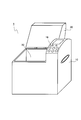
- the schematic perspective view which shows the external appearance structure of the automatic bread maker of this embodiment
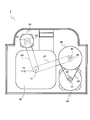
- the schematic diagram for demonstrating the structure inside the main body of the automatic bread maker of this embodiment.
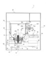
- the figure which shows the structure in case the 1st bread container is used with the partial cross section figure which shows schematic structure of the automatic bread maker of this embodiment.
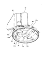
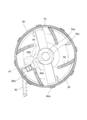
- the automatic bread maker of this embodiment it is a figure for demonstrating the structure of the grinding
- the schematic perspective view which shows the structure of the guard with which the automatic bread maker of this embodiment is provided.
- FIG. 1 is a schematic perspective view showing an external configuration of the automatic bread maker according to the present embodiment.
- an operation unit 16 is provided on the upper right side of the main body 10 (for example, formed of synthetic resin) of the automatic bread maker 1.
- the operation unit 16 displays an operation key group including a start key, a cancel key, a timer key, a reservation key, a selection key for selecting a bread production course, and contents and errors set by the operation key group.
- a display unit is provided.
- the bread production course includes a course for making bread using rice grains as a starting material, a course for making bread using rice flour as a starting material, a course for making bread using wheat flour as a starting material, etc. It is.
- the display unit includes, for example, a display lamp using a liquid crystal display panel or a light emitting diode as a light source.
- the main body 10 is formed with a baking chamber 30 in which a bread container (details will be described later) is accommodated so as to be adjacent to the operation unit 16.
- the firing chamber 30 formed of sheet metal is formed in a substantially rectangular shape in plan view and has an upper surface opened.
- the main body 10 is provided with a lid 20 (for example, formed of synthetic resin) that covers the baking chamber 30.
- the lid 20 is attached to the back side of the main body 10 with a hinge shaft (not shown), and the opening of the baking chamber 30 can be opened and closed by rotating about the hinge shaft.
- the lid 20 is provided with a viewing window made of heat-resistant glass, for example, so that the user can look inside the baking chamber 30.
- FIG. 2 is a schematic diagram for explaining the internal configuration of the main body of the automatic bread maker according to the present embodiment.
- FIG. 2 assumes a case where the automatic bread maker 1 is viewed from above.
- a low-speed / high-torque type kneading motor 40 used in the kneading process is disposed on the right side of the baking chamber 30.
- a high-speed rotation type crushing motor 50 used in the crushing process is fixedly disposed on the rear side of the baking chamber 30.
- the kneading motor 40 and the grinding motor 50 are both shafts.
- the kneading motor 40 is an example of the second motor of the present invention.
- the grinding motor 50 is an example of the first motor of the present invention.
- the first pulley 42 is fixed to the output shaft 41 protruding from the upper surface of the kneading motor 40.
- the first pulley 42 is connected to the second pulley 45 by the first belt 43.
- the diameter of the second pulley 45 is larger than that of the first pulley 42 and is fixed to the upper end side of the rotating shaft 44.
- a third pulley 46 is fixed to the lower end side of the rotating shaft 44.
- a clutch mechanism (not shown) is provided between a portion of the rotating shaft 44 where the second pulley 45 is fixed and a portion where the third pulley 46 is fixed. And by this clutch mechanism, between the 2nd pulley 45 and the 3rd pulley 46, it is switchable whether one rotational force is transmitted to the other.
- the third pulley 46 is connected to the first driving shaft pulley 12 (having substantially the same diameter as the third pulley 46) by a second belt 47.
- the first driving shaft pulley 12 is fixed to a driving shaft 11 provided on the lower side of the firing chamber 30.
- the kneading motor 40 itself is of a low speed / high torque type, and the rotation of the first pulley 42 is decelerated and rotated by the second pulley 45. Therefore, when the kneading motor 40 is driven, the driving shaft 11 is driven at a low speed / high torque. It rotates with torque.
- a fourth pulley 52 is fixed to the output shaft 51 protruding from the lower surface of the grinding motor 50.
- the fourth pulley 52 is coupled to a second driving shaft pulley 13 (fixed below the first driving shaft pulley 12) fixed to the driving shaft 11 by a third belt 53. ing.
- the second driving shaft pulley 13 has substantially the same diameter as the fourth pulley 52.
- the grinding motor 50 is selected to rotate at a high speed, and the rotation of the fourth pulley 52 is maintained substantially the same in the second driving shaft pulley 13. For this purpose, when the grinding motor 50 is driven, the driving shaft 11 rotates at a high speed (for example, 7000 to 8000 rpm).
- the clutch mechanism provided between the second pulley 45 and the third pulley 46 described above is in a state in which the mutual rotation is not transmitted, and the crushing motor 50 is operated at a high speed. Even if it rotates, the rotation is not transmitted to the kneading motor 40.
- the automatic bread maker 1 of this embodiment can bake bread using rice grain (embodiment of grain) as a starting material, and also uses wheat flour and rice flour (both embodiments of grain flour) as a starting material. It can also be used to bake bread. And it is the structure by which a different thing is used about the bread container into which a bread raw material is thrown by the case where a rice grain is used for a starting material, and the case where wheat flour and rice flour are used for a starting material.
- the first bread container is used when rice grains are used as the starting material
- the second bread container is used when wheat flour or rice flour is used as the starting material.
- the configuration in the case where the first bread container is used and the configuration in the case where the second bread container is used will be described separately.
- FIG. 3 is a partial cross-sectional view showing a schematic configuration of the automatic bread maker of the present embodiment, and is a diagram showing a configuration in the case where the first bread container is used. .
- FIG. 3 assumes a case where the automatic bread maker is viewed from the front side.
- a sheathed heater 31 surrounds a first bread container 60 (which may be replaced with a second bread container 100 described later) housed in the baking chamber 31 inside the baking chamber 30.
- a first bread container 60 which may be replaced with a second bread container 100 described later
- the bread raw material in the 1st bread container 60 can be heated now.
- a bread container support portion 14 that supports a first bread container 60 (which may be replaced with a second bread container 100 described later) is fixed to a location corresponding to the approximate center of the bottom wall 30a of the baking chamber 30. Yes.
- the bread container support portion 14 is made of, for example, an aluminum alloy die cast product.
- the bread container support 14 is formed so as to be recessed from the bottom wall 30a of the baking chamber 30, and the shape of the recess is substantially circular in plan view.
- the driving shaft 11 is vertically supported at the center of the bread container support 14.
- the first pan container 60 is, for example, an aluminum alloy die cast product.
- the first bread container 60 has a bucket-like shape, and a handle (not shown) for handing is attached to a flange 60a provided on the side edge of the opening.
- the horizontal section of the first bread container 60 is a rectangle with rounded corners.
- a concave portion 61 having a substantially circular shape in a plan view for accommodating a grinding blade 70 and a cover 80, which will be described later in detail, is formed at the bottom of the first bread container 60.
- the first blade rotating shaft 62 extending in the vertical direction is supported at the center of the bottom of the first bread container 60 in a state where a countermeasure against sealing is taken.
- a container-side coupling member 62a is fixed to the lower end of the first blade rotating shaft 62 (the lower end is outside the first bread container 60).
- a cylindrical pedestal 63 is provided on the outer bottom surface of the first bread container 60, and the first bread container 60 is a baking chamber in a state where the pedestal 63 is received by the bread container support part 14. 30 is arranged inside.
- the pedestal 63 may be formed separately from the first bread container 60 or may be formed integrally with the first bread container 60.
- the inner peripheral surface of the bread container support part 14 and the outer peripheral surface of the pedestal 63 are formed with protrusions (not shown), and these protrusions constitute a known bayonet connection. That is, when the first bread container 60 is attached to the bread container support part 14, the first bread container 60 is lowered such that the protrusion of the base 63 does not interfere with the protrusion of the bread container support part 14. When the first bread container 60 is twisted horizontally after the pedestal 63 is fitted into the bread container support part 14, the protrusion of the pedestal 63 is engaged with the lower surface of the protrusion of the bread container support part 14. ing. As a result, the first bread container 60 cannot be pulled upward.
- the coupling (coupling) between the container side coupling member 62a provided on the first blade rotating shaft 62 and the driving shaft side coupling member 11a fixed to the upper end of the driving shaft 11 is also performed. Achieved at the same time.
- the rotational force is transmitted from the driving shaft 11 to the first blade rotating shaft 62.
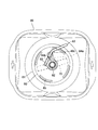
- FIG. 4 is a diagram for explaining the configuration of a grinding blade and a kneading blade used when the first bread container is used in the automatic bread maker of the present embodiment, and is an outline when viewed obliquely from below.
- FIG. 5 is a diagram for explaining the configuration of the crushing blade and the kneading blade used when the first bread container is used in the automatic bread maker of the present embodiment, and is a schematic view when viewed from below. It is.
- the crushing blade 70 (formed by, for example, a stainless steel plate) has a shape like an airplane propeller and is non-rotatably attached to the first blade rotating shaft 62. .
- a central portion of the crushing blade 70 is a hub 70 a that is fitted to the first blade rotating shaft 62.
- a groove 70b is formed on the lower surface of the hub 70a so as to cross the hub 70a in the diameter direction.
- the crushing blade 70 can be easily pulled out from the first blade rotating shaft 62, it can be easily washed after the bread making operation and replaced when the sharpness is deteriorated.
- a dome-shaped cover 80 surrounds and covers the grinding blade 70 as shown in FIG.
- the cover 80 is rotatably supported by the hub 70a of the grinding blade 70, and is prevented from being removed from the hub 70a by a washer 80a and a retaining ring 80b (see FIG. 3). That is, in this embodiment, the pulverizing blade 70 and the cover 80 constitute a unit that cannot be separated.
- the hub 70a of the crushing blade 70 also serves as a rotary bearing insertion portion that receives the first blade rotating shaft 62 in the cover 80.
- this cover 80 can be easily pulled out from the first blade rotating shaft 62 together with the grinding blade 70, it is possible to easily perform the cleaning after the bread making operation is completed.
- a kneading blade 82 having a square shape “ ⁇ ” is formed by a vertically extending support shaft 81 (see FIG. 5) disposed at a position away from the first blade rotation shaft 62. (For example, made of an aluminum alloy die-cast product) is attached.
- the support shaft 81 is fixed to or integrated with the kneading blade 82 and moves together with the kneading blade 82.
- a complementary kneading blade 83 is provided on the outer surface of the cover 80 so as to line up with the kneading blade 82.
- the complementary kneading blade 83 is not necessarily provided, but is preferably provided in order to increase the efficiency in the kneading process of kneading bread dough.
- the kneading blade 82 and the complementary kneading blade 83 constitute an embodiment of the first kneading blade of the present invention.
- FIGS. 6 and 7 are views of the first bread container 60 as viewed from above, and the kneading blade 82 is different in FIGS. 6 and 7.
- the kneading blade 82 rotates around the axis of the support shaft 81 together with the support shaft 81, and takes two postures, a folded posture shown in FIG. 6 and an open posture shown in FIG. In the folded position, a protrusion 82a (see FIG. 4) hanging from the lower edge of the kneading blade 82 abuts on a first stopper portion 80c provided on the upper surface of the cover 80. For this reason, in the folded position, the kneading blade 82 cannot rotate further clockwise (assuming the case viewed from above) with respect to the cover 80. At this time, the tip of the kneading blade 82 slightly protrudes from the cover 80.
- the tip of the kneading blade 82 protrudes greatly from the cover 80.
- the opening angle of the kneading blade 82 in this opening posture is limited by the second stopper portion 80 d (see FIGS. 4 and 5) provided on the inner surface of the cover 80.
- the kneading blade 82 reaches the maximum opening angle when a second engagement body 84b constituting a clutch 84 (see FIG. 5) described later cannot rotate by hitting the second stopper portion 80d.
- the complementary kneading blade 83 is aligned with the kneading blade 82 as shown in FIG. 6, and the size of the k-shaped kneading blade 82 is increased. It becomes like.
- a clutch 84 is interposed between the cover 80 and the first blade rotating shaft 62 as shown in FIG.
- the clutch 84 rotates in the rotation direction of the first blade rotation shaft 62 when the kneading motor 40 rotates the drive shaft 11 (this rotation direction is “forward rotation”, which is clockwise rotation in FIG. 5).
- the first blade rotating shaft 62 and the cover 80 are connected.
- in the rotation direction of the first blade rotation shaft 62 when the crushing motor 50 rotates the driving shaft 11 this rotation direction is referred to as “reverse rotation”, which is counterclockwise rotation in FIG. 5).
- the clutch 84 disconnects the connection between the first blade rotating shaft 62 and the cover 80.
- the “forward rotation” is a counterclockwise rotation
- the “reverse rotation” is a clockwise rotation.
- the clutch 84 includes a first engagement body 84a and a second engagement body 84b.
- the first engaging body 84a is fixed to the hub 70a of the grinding blade 70, or is integrally formed with the hub 70a.
- the first engagement body 84 a is attached to the first blade rotation shaft 62 so as not to rotate while the grinding blade 70 is attached to the first blade rotation shaft 62.
- the second engagement body 84 b is fixed to the support shaft 81 of the kneading blade 82 or is integrally formed with the support shaft 81, and changes the angle as the posture of the kneading blade 82 is changed.
- the second engagement body 84b When the kneading blade 82 is in the folded posture (for example, the state shown in FIG. 5), the second engagement body 84b has an angle that interferes with the rotation track of the first engagement body 84a. Therefore, when the first blade rotation shaft 62 rotates in the forward direction (clockwise rotation in FIG. 5 and counterclockwise rotation in FIG. 6), the first engagement body 84a and the second engagement body 84b are engaged, and the first The rotational force of the blade rotation shaft 62 is transmitted to the cover 80 and the kneading blade 82.
- the second engaging body 84b has an angle deviating from the rotation trajectory of the first engaging body 84a. For this reason, even if the first blade rotating shaft 62 rotates in the reverse direction (clockwise in FIG. 7), the first engaging body 84a and the second engaging body 84b are not engaged. Accordingly, the rotational force of the first blade rotating shaft 62 is not transmitted to the cover 80 and the kneading blade 82. As can be seen from the above, the clutch 84 switches the connection state between the first blade rotating shaft 62 and the cover 80 according to the attitude of the kneading blade 82.
- the cover 80 is formed with a window 85 that communicates the space inside the cover and the space outside the cover.
- the window 85 is arranged at a height equal to or higher than the grinding blade 70.
- a total of four windows 85 are arranged at 90 ° intervals, but other numbers and arrangement intervals may be selected.
- each rib 86 extends obliquely from the vicinity of the center of the cover 80 to the outer peripheral annular wall with respect to the radial direction, and a total of four ribs 86 constitute a kind of bowl shape.
- each rib 86 is curved so that the side facing the bread ingredients that press toward it is convex.
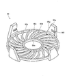
- FIG. 8 is a schematic perspective view showing a configuration of a guard provided in the automatic bread maker of the present embodiment.
- a ring-shaped hub 90a through which the first blade rotating shaft 62 passes.
- a ring-shaped rim 90b is provided at the periphery of the guard 90.
- the hub 90a and the rim 90b are connected by a plurality of spokes 90c. Between the spokes 90c is an opening 90d through which the rice grains crushed by the pulverizing blade 70 are passed.
- the opening 90d has a size that prevents a finger from passing through.
- the guard 90 When the guard 90 is attached to the cover 80, the guard 90 is in the proximity of the grinding blade 70.
- the guard 90 is shaped like an outer blade of a rotary electric razor, and the grinding blade 70 is shaped like an inner blade.
- a total of four (not limited to this configuration) pillars 90e are integrally formed at the periphery of the rim 90b at intervals of 90 °.
- a horizontal groove 90f whose one end is a dead end is formed on a side surface of the column 90e facing the center side of the guard 90.
- the guard 90 is attached to the cover 80 by engaging the projections 80e (in the embodiment, a total of eight protrusions are arranged at 45 ° intervals) formed on the outer periphery of the cover 80 in the groove 90f.
- the groove 90f and the protrusion 80e are provided so as to constitute a bayonet connection.
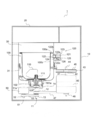
- FIG. 9 is a partial cross-sectional view showing a schematic configuration of the automatic bread maker of the present embodiment, and shows a configuration when the second bread container is used. It is. FIG. 9 assumes a case where the automatic bread maker is viewed from the front side. In addition, the description of the same configuration as that in the case where the first bread container 60 is used is omitted if there is no need for description.
- the second bread container 100 (for example, made of sheet metal) has a bucket-like shape like the first bread container 60, and a handle (not shown) for handing the hook 100a provided on the side edge of the opening. Is attached.
- the second bread container 100 also has a rectangular shape with rounded corners.
- the recessed part 61 like the 1st bread container 60 is not formed in the bottom part of the 2nd bread container 100.
- FIG. This is related to the fact that when the second bread container 100 is used, there is no crushing step and it is not necessary to attach the crushing blade 70.
- the second bread container 100 does not need to be provided with the recess 61, and therefore has a lower height than the first bread container 60.
- a second blade rotating shaft 101 extending in the vertical direction is supported in a state where measures against sealing are taken.
- a container-side coupling member 101a is fixed to the lower end of the second blade rotating shaft 101 (this lower end is outside the second bread container 100).
- a cylindrical pedestal 102 is provided on the outer bottom surface of the second bread container 100, and the second bread container 100 is in a baking chamber in a state where the pedestal 102 is received by the bread container support 14. 30 is arranged inside.
- the method for coupling the pedestal 102 and the bread container support 14 is the same as the method for coupling the pedestal 63 of the first bread container 60 and the bread container support 14. Further, the coupling between the pedestal 102 and the bread container support portion 14 connects the container side coupling member 101 a provided on the second blade rotating shaft 101 and the driving shaft side coupling member 11 a fixed to the driving shaft 11. (Coupling) is also achieved. By this coupling, the second blade rotating shaft 101 can transmit a rotational force from the driving shaft 11.
- a second kneading blade 110 (for example, an aluminum alloy die cast product) is attached to the upper end of the second blade rotating shaft 101.
- the second kneading blade 110 has a shape that integrates the above-described kneading blade 82 and the complementary kneading blade 83 (both constituting the first kneading blade), and the hub 111 is a second blade rotating shaft.
- the upper end of 101 is non-rotatably connected.
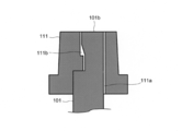
- FIG. 10A and 10B are diagrams for explaining the relationship between the hub of the second kneading blade and the second blade rotation shaft in the second bread container, FIG. 10A is a cross-sectional view, and FIG. 10B is a top view. It is.
- the center hole of the hub 111 of the second kneading blade 110 is a circular hole 111a at a predetermined height from the lower end, and the upper part is a D-shaped hole 111b.
- the D-shaped hole portion 111 b has a step structure in which a lower portion corresponding to a D-shaped string projects toward the center of the second blade rotating shaft 101.
- the second blade rotating shaft 101 has a circular cross section up to a point where a distance is left to the upper end, and the upper portion is a D-shaped cross section 101b.
- the D-shaped cross-sectional portion 101b has a stepped structure in which an upper portion of a portion that contacts the D-shaped string protrudes.
- the D-shaped hole portion 111b and the D-shaped cross-sectional portion 101b are combined so that the protruding portion of the D-shaped cross-section portion 101b is overhanging with respect to the protruding portion of the D-shaped hole portion 111b.
- the hub 111 of the second kneading blade 110 is non-rotatably connected to the second blade rotating shaft 101. Since the hub 111 and the second blade rotation shaft 101 are loosely fitted, the second blade rotation shaft 101 can be passed through the hub 111 without any problem, and the overhanged state can be obtained. Further, when power is transmitted to the second blade rotating shaft 101, as shown in FIG.
- a micro switch 120 which is an embodiment of a bread container detection unit, is attached to one of the four side walls 30 b of the baking chamber 30 of the automatic bread maker 1.
- the micro switch 120 has a main body 121 fixedly disposed on the outer surface side of the side wall 30 b of the baking chamber 30.
- the micro switch 120 is attached to the firing chamber 30 such that the button 122 is fitted into an opening provided in the side wall 30b of the firing chamber 30 and the tip of the button 122 protrudes toward the inside of the firing chamber 30. Yes.
- the button 122 of the micro switch 120 is biased toward the inside of the baking chamber 30 by a spring 123 (biased in the left direction in FIGS. 3 and 9). And the flange part 122a provided in the trunk
- a slope 122b is formed on the upper end of the button 122 so as to taper toward the front end.
- the mounting position of the micro switch 120 is adjusted so that the position of the button 122 is substantially the same as the height of the flange 100a of the second bread container 100 accommodated in the baking chamber 30. Further, the amount of protrusion of the button 122 from the side wall 30b of the baking chamber 30 is such that, in the state where the first bread container 60 and the second bread container 100 are accommodated in the baking chamber 30, the button 122 is the side wall 60b of the bread container. It is adjusted not to contact 100b. Further, the protruding amount of the button 122 from the side wall 30b of the baking chamber 30 is adjusted such that the button 122 is pressed by the collar 100a and the switch is turned on in the state where the second bread container 100 is accommodated. ing.
- the flange portion 100 a abuts on a slope 122 b provided on the front end side of the button 122, and the button 122 is opposite to the protruding direction (rightward in FIG. 9). ) Is applied, and the button 122 starts moving.
- the movable contact 125 is pressed by the protrusion 122c provided on the rear end side of the button 122 and comes into contact with the fixed contact 126, and the micro switch 120 is turned on (state of FIG. 9). .
- the button 122 When the second bread container 100 is taken out from the baking chamber 30, the button 122 is not pressed, so that the button 122 is moved in the direction toward the inside of the baking chamber 30 by the spring 123 (leftward in FIG. 9). Moving. Thereby, the contact between the movable contact 125 and the fixed contact 126 is released, and the on state of the micro switch 120 is released (the micro switch 120 is turned off).
- the microswitch 120 is not turned on as shown in FIG.
- the protruding amount of the button 122 from the side wall 30 b of the baking chamber 30 is adjusted so as not to contact the side wall 60 b of the first bread container 60.
- the first bread container 60 is higher in height than the second bread container 100 because of the configuration having the recess 61.
- the flange portion 60 a closest to the side wall 30 b of the baking chamber 30 is located higher than the button 122 of the microswitch 120. Therefore, the collar 60 a does not press the button 122 of the micro switch 120.
- the micro switch 120 is turned on when the second bread container 100 is accommodated in the baking chamber 30, but the first bread container 60 is accommodated in the baking chamber 30. If turned on, it does not turn on. That is, the microswitch 120 is a bread container detection unit that detects that the second bread container 100 is accommodated in the baking chamber 30.
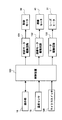
- FIG. 11 is a block diagram showing a configuration of the automatic bread maker according to the present embodiment.
- the microswitch 120 is electrically connected to a control device 130 (an example of a control unit of the present invention) that controls the operation of the automatic bread maker 1. Therefore, the control device 130 can determine whether the bread container accommodated in the baking chamber 30 is the first bread container 60 or the second bread container 100 by turning the micro switch 120 on and off. Specifically, when the microswitch 120 is in an on state, it is determined that the second bread container 100 is accommodated in the baking chamber 30. Further, when the microswitch 120 is in the off state, it is determined that the first bread container 60 is accommodated in the baking chamber 30.
- the control apparatus 130 can determine whether the bread container accommodated in the baking chamber 30 is the 1st bread container 60 or the 2nd bread container 100.
- the control device 130 can be controlled as follows. For example, when a command to drive the grinding motor 50 is input from the operation unit 16 when the second bread container 100 is accommodated in the baking chamber 30 (when a bread making course with a grinding process is selected). Can display an error indication. For example, when the 2nd bread container 100 is accommodated in the baking chamber 30, it can also be made impossible to select the bread making course which drives the grinding motor 50 from the beginning.
- the control device 130 is constituted by, for example, a microcomputer comprising a CPU (Central Processing Unit), a ROM (Read Only Memory), a RAM (Random Access Memory), an I / O (input / output) circuit unit, and the like. Is done.
- the control device 130 is preferably disposed at a position that is not easily affected by the heat of the baking chamber 30.
- the control device 130 is provided with a time measuring function, and temporal control in the bread manufacturing process is possible.
- the operation unit 16 In addition to the micro switch 120, the operation unit 16, the temperature sensor 15, the grinding motor drive circuit 131, the kneading motor drive circuit 132, and the heater drive circuit 133 are electrically connected to the control device 130. ing.
- the temperature sensor 15 is a sensor provided so that the temperature of the baking chamber 30 can be detected.
- the crushing motor drive circuit 131 is a circuit that controls the driving of the crushing motor 50 under a command from the control device 130.
- the kneading motor driving circuit 133 is a circuit that controls the driving of the kneading motor 40 under a command from the control device 130.
- the heater drive circuit 133 is a circuit that controls the operation of the sheathed heater 31 under a command from the control device 130.
- the control device 130 reads a program related to a bread manufacturing course (breadmaking course) stored in a ROM or the like based on an input signal from the operation unit 16.
- the control device 130 controls the rotation of the grinding blade 70 via the grinding motor drive circuit 131, and rotates the kneading blade 82 and the complementary kneading blade 83 or the second kneading blade 110 via the kneading motor drive circuit 132.
- the automatic bread maker 1 executes the bread manufacturing process while controlling the heating operation by the sheathed heater 31 via the heater driving circuit 133.
- the automatic bread maker 1 of the present embodiment includes a case where bread is produced using rice grains as a starting material, and a case where bread is produced using milled powder such as wheat flour and rice flour as a starting material. Different bread containers are used. For this reason, the operation of the automatic bread maker 1 will be described separately for the case where the first bread container 60 is used and the case where the second bread container 100 is used.
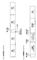
- FIG. 12 is a schematic diagram showing the flow of the rice grain bread-making course executed by the automatic bread maker 1. As shown in FIG. 12, in the bread making course for rice grains, the dipping process, the pulverizing process, the kneading (kneading) process, the fermentation process, and the baking process are sequentially performed in this order.
- the user In executing the rice grain breadmaking course, the user attaches the grinding blade 70, the kneading blade 82, and the cover 80 with the complementary kneading blade 83 to the first bread container 60. Then, the user measures a predetermined amount of each of the rice grains and water and puts them in the first bread container 60.
- rice grains and water are mixed, but instead of mere water, for example, a liquid having a taste component such as broth, fruit juice, a liquid containing alcohol, or the like may be used.
- the user puts the first bread container 60 into which the rice grains and water are put into the baking chamber 30, closes the lid 20, selects the rice grain breadmaking course by the operation unit 16, and presses the start key. Thereby, the bread-making course for rice grain which manufactures bread using the rice grain as a starting material by the control apparatus 130 is started.
- the control device 130 determines that the bread container accommodated in the baking chamber 30 is the first bread container 60, and performs control to prevent the grinding motor 50 from being erroneously driven. Absent. For this purpose, the user can select the bread making course for rice grains and start producing bread.
- the dipping process is started by a command from the control device 130.
- the mixture of rice grains and water is allowed to stand, and this standing state is maintained for a predetermined time (in this embodiment, 50 minutes).
- This dipping process is a process aimed at making the rice grains easy to be pulverized to the core in the subsequent pulverization process by adding water to the rice grains.
- the water absorption speed of rice grains varies depending on the temperature of the water. If the water temperature is high, the water absorption speed increases, and if the water temperature is low, the water absorption speed decreases. For this reason, you may make it fluctuate the time of an immersion process with the environmental temperature etc. in which the automatic bread maker 1 is used, for example. Thereby, the dispersion
- the crushing blade 70 may be rotated at the initial stage, and the crushing blade 70 may be rotated intermittently thereafter. If it does in this way, the surface of a rice grain can be damaged, and the liquid absorption efficiency of a rice grain will be improved.
- the dipping process is terminated by a command from the control device 130, and the crushing process for crushing the rice grains is started.
- the crushing blade 70 is rotated at a high speed in the mixture of rice grains and water.
- the control device 130 controls the crushing motor 50 to rotate the first blade rotating shaft 62 in the reverse direction to start the rotation of the crushing blade 70 in the mixture of rice grains and water.
- the cover 80 also starts rotating following the rotation of the first blade rotating shaft 62, but the rotation of the cover 80 is immediately prevented by the following operation.
- the rotation direction of the cover 80 accompanying the rotation of the first blade rotation shaft 62 for rotating the grinding blade 70 is the clockwise direction in FIG. 6, and the kneading blade 82 has been folded until then (the posture shown in FIG. 6). If it is, the resistance is changed from the rice grain and water mixture to the open posture (posture shown in FIG. 7).
- the clutch 84 disconnects the connection between the first blade rotation shaft 62 and the cover 80 because the second engagement body 84b deviates from the rotation track of the first engagement body 84a.
- the kneading blade 82 in the open position abuts against the inner wall of the first bread container 60, so that the cover 80 is prevented from rotating.
- the pulverization of the rice grains in the pulverization step is performed in a state in which water is soaked in the rice grains by the previously performed immersion step, so that the rice grains can be easily pulverized to the core.
- the rotation of the pulverizing blade 70 in the pulverization process is intermittent. This intermittent rotation is performed, for example, in a cycle of rotating for 30 seconds and stopping for 5 minutes, and this cycle is repeated 10 times. In the last cycle, the stop for 5 minutes is not performed.
- the rotation of the crushing blade 70 may be continuous rotation, but for the purpose of, for example, preventing the raw material temperature in the first bread container 60 from becoming too high, it is preferable to perform intermittent rotation.
- the possibility that the rice grains are scattered outside the first bread container 60 is low. Further, the rice grains entering the cover 80 from the opening 90d of the guard 90 in the rotation stopped state are sheared between the stationary spoke 90c and the rotating pulverizing blade 70, so that they can be efficiently pulverized. Further, the rib 86 provided on the cover 80 suppresses the flow of the mixture of rice grains and water (the flow in the same direction as the rotation of the grinding blade 70), so that the grinding can be performed efficiently.
- the mixture of the pulverized rice grains and water is guided toward the window 85 by the ribs 86 and discharged from the window 85 to the outside of the cover 80. Since the rib 86 is curved so that the side facing the mixture pressing toward it is convex, the mixture hardly stays on the surface of the rib 86 and flows smoothly toward the window 85. Furthermore, instead of the mixture being discharged from the inside of the cover 80, the mixture existing in the space above the recess 61 enters the recess 61, and enters the cover 80 from the recess 61 through the opening 90d of the guard 90. . Since the pulverization by the pulverization blade 70 is performed while being circulated as described above, the pulverization can be performed efficiently.
- the crushing process is completed in a predetermined time (in this embodiment, 50 minutes).
- the grain size of the pulverized powder may vary depending on the hardness of the rice grains and the environmental conditions. For this reason, it is possible to adopt a configuration in which the end of the pulverization process is determined using the magnitude of the load of the pulverization motor 50 at the time of pulverization (for example, it can be determined by the control current of the motor) as an index.
- the kneading process is performed subsequently.
- this kneading process needs to be performed at a temperature (for example, around 30 ° C.) at which the yeast actively works.
- a kneading process is started when it becomes a predetermined temperature range.
- a predetermined amount of each seasoning such as gluten, salt, sugar, and shortening is charged into the first bread container 60.
- These bread ingredients may be input by, for example, the user's hand, or may be input without bothering the user by providing an automatic input device.
- gluten is not essential as a bread ingredient. For this reason, you may judge whether to add to a bread raw material according to liking. Further, flour or a thickening stabilizer (for example, guar gum) may be used instead of gluten or together with gluten. Moreover, the amount of seasonings such as salt, sugar, and shortening may be appropriately changed according to the user's preference.
- a thickening stabilizer for example, guar gum
- the control device 130 controls the kneading motor 40 to rotate the first blade rotating shaft 62 in the forward direction.
- the grinding blade 70 is also rotated in the forward direction, and the bread ingredients around the grinding blade 70 flow in the forward direction.
- the cover 80 moves in the forward direction, the kneading blade 82 receives resistance from the non-flowing bread ingredients and changes the angle from the open position (see FIG. 7) to the folded position (see FIG. 6). .
- the clutch 84 When the second engagement body 84b has an angle that interferes with the rotation track of the first engagement body 84a, the clutch 84 is connected, and the cover 80 enters a state of being driven in earnest by the rotation of the first blade rotation shaft 62. .
- the kneading blade 82 in a folded posture with the cover 80 rotates in the forward direction integrally with the first blade rotating shaft 62.
- the complementary kneading blade 83 is arranged on the extension of the kneading blade 82, so that the kneading blade 82 is enlarged and the bread raw material is pushed strongly. For this reason, the dough can be kneaded firmly.
- the rotation of the kneading blade 82 and the complementary kneading blade 83 in the kneading process may be continuous rotation from beginning to end.
- intermittent rotation is performed in the initial stage of the kneading process, and continuous rotation is performed in the latter half.
- yeast for example, dry yeast
- the yeast may be input by the user or may be automatically input.
- the reason why yeast is not added together with gluten or the like is to avoid direct contact between yeast (dry yeast) and water as much as possible. However, in some cases, yeast may be added simultaneously with gluten or the like.
- the bread material is kneaded by the rotation of the kneading blade 82 and the complementary kneading blade 83, and is kneaded into a dough connected to one having a predetermined elasticity.
- the kneading blade 82 and the complementary kneading blade 83 shake the dough and knock it against the inner wall of the first bread container 60, so that a “kneading” element is added to the kneading.
- the cover 80 also rotates together with the kneading blade 82 and the complementary kneading blade 83.
- the rib 86 formed on the cover 80 also rotates, so that the bread ingredients in the cover 80 are quickly discharged from the window 85.
- the discharged bread ingredients are assimilated into a lump (dough) of the bread ingredients kneaded by the kneading blade 82 and the complementary kneading blade 83.
- the cover 90 and the guard 90 also rotate in the forward direction.
- the spoke 90c of the guard 90 has a shape in which the center side of the guard 90 precedes and the outer periphery side of the guard 90 follows when rotating in the forward direction.
- the guard 90 rotates in the forward direction to push the bread ingredients inside and outside the cover 80 outward with the spokes 90c. Thereby, the ratio of the raw material used as a waste after baking bread can be reduced.
- the column 90e of the guard 90 has a side surface 90g (see FIG. 8) that is the front surface in the rotation direction when the guard 90 rotates in the forward direction, the bread ingredients around the cover 80 are kneaded. Is flipped up in front of the pillar 90e. For this reason, the ratio of the raw material which becomes waste after baking bread can be reduced.
- the kneading process is configured to employ a predetermined time (10 minutes in the present embodiment) obtained experimentally as a time for obtaining bread dough having a desired elasticity.
- a predetermined time 10 minutes in the present embodiment
- the degree of bread dough may vary depending on the environmental temperature or the like.
- the configuration may be such that the end point of the kneading process is determined based on the magnitude of the load of the kneading motor 40 (for example, it can be determined by the control current of the motor).
- the ingredients may be introduced during the kneading process.
- the fermentation process is started by a command from the control device 130.
- the control device 130 controls the sheathed heater 31 to maintain the temperature of the baking chamber 30 at a temperature at which fermentation proceeds (for example, 38 ° C.).
- the bread dough is left for a predetermined time (60 minutes in this embodiment).
- the kneading blade 82 and the complementary kneading blade 83 may be rotated to perform degassing or rounding of the dough.
- the firing process is started by a command from the control device 130.
- the control device 130 controls the sheathed heater 31 to raise the temperature of the baking chamber 30 to a temperature suitable for baking (for example, 125 ° C.). Then, baking is performed for a predetermined time (in this embodiment, 50 minutes) in a baking environment.
- the end of the firing process is notified to the user by, for example, a display on a liquid crystal display panel (not shown) of the operation unit 16 or a notification sound.
- the user detects the completion of bread making, the user opens the lid 20 and takes out the first bread container 60 to complete the bread production.
- the cover 80 and the guard 90 are in a state of being accommodated in the recess 61, so that they leave a large burn mark at the bottom of the bread. There is nothing.
- FIG. 12 is a schematic diagram showing the flow of the flour bread course executed by the automatic bread maker 1.
- a kneading (kneading) process a primary fermentation process, a degassing process, a dough resting process (also called bench time or nekashi), a dough rounding process, A shaping
- the user In executing the flour bread course, the user attaches the second kneading blade 110 to the second bread container 100. Then, after putting a predetermined amount of water into the second bread container 100, the user puts a predetermined amount of flour, salt, sugar and shortening, and finally the second bread so that the dry yeast does not touch the water. Place in container 100. Note that the amount of seasonings such as salt, sugar, and shortening may be appropriately changed according to the user's preference. Thereafter, the user puts the second bread container 100 into the baking chamber 30, closes the lid 20, selects a flour bread course by the operation unit 16, and presses the start key. Thereby, the bread
- the control device 130 determines that the bread container accommodated in the baking chamber 30 is the second bread container 100, and executes control to prevent a situation in which the grinding motor 50 is erroneously driven. To do. That is, the control device 130 makes it impossible to start the rice grain breadmaking course, for example, by making it impossible to select the rice grain breadmaking course or by displaying an error display even if the rice grain breadmaking course is selected. .
- the kneading process is started by a command from the control device 130.
- the control device 130 controls the kneading motor 40 to rotate the second blade rotating shaft 101 in the forward direction.
- the second kneading blade 110 is rotated at a low speed and a high torque.
- the rotation of the second kneading blade 110 is controlled by the control device 130 so as to be very slow at the initial stage of the kneading process, and the speed is increased stepwise.
- the bread ingredients in the second bread container 100 are kneaded and kneaded into one dough having a predetermined elasticity.
- an element of “kneading” is added to the kneading. This kneading step is performed for a predetermined time (12 minutes in the present embodiment) experimentally obtained as a time for obtaining bread dough having a desired elasticity.
- the ingredients may be introduced during the kneading process.
- a primary fermentation process for fermenting the bread dough is started according to a command from the control device 130.
- the control device 130 controls the sheathed heater 31 to maintain the temperature of the baking chamber 30 at a predetermined temperature (32 ° C. in this embodiment) at which fermentation proceeds.
- the primary fermentation process is performed for 48 minutes and 50 seconds.
- a degassing process for extracting gas contained in the bread dough is started according to a command from the control device 130.
- the control device 130 controls the driving of the kneading motor 40 to continuously rotate the second kneading blade 110 for a predetermined time (in this embodiment, 10 seconds).
- the controller 130 also controls the sheathed heater 31 so as to maintain the temperature of the firing chamber 30 at a predetermined temperature.
- a dough resting process (bench time; sometimes referred to as “nekashi”) for resting the dough according to a command from the control device 130 is executed.
- the control device 130 controls the sheathed heater 31 to maintain the temperature of the baking chamber 30 at a predetermined temperature (32 ° C. in the present embodiment).
- the bench time is performed in this embodiment (35 minutes and 30 seconds).
- a dough rounding process for rounding the bread dough is started according to a command from the control device 130.
- the control device 130 controls the driving of the kneading motor 40 and rotates the second kneading blade 110.
- the second kneading blade 110 is rotated very slowly for a predetermined time (1 minute 30 seconds in this embodiment).
- a molding fermentation process is performed in which the bread dough is fermented again according to a command from the control device 130.
- the control device 130 controls the sheathed heater 31 to set the temperature of the baking chamber 30 to a predetermined temperature (38 ° C. in this embodiment) at which fermentation proceeds, and this state for a predetermined time (in this embodiment). 60 minutes).
- a baking process for baking bread dough is executed according to a command from the control device 130.
- the controller 130 controls the sheath heater 31 to raise the temperature of the baking chamber 30 to a temperature suitable for baking (120 ° C. in this embodiment).
- the bread is baked for a predetermined time (47 minutes in this embodiment) in a baking environment.
- the end of the firing process is notified to the user by, for example, a display on a liquid crystal display panel (not shown) of the operation unit 16 or a notification sound.
- the user detects the completion of bread making, the user opens the lid 20 and takes out the second bread container 100 to complete the bread production.
- the microswitch 120 is not turned on when neither the first bread container 60 nor the second bread container 100 is contained in the baking chamber 30. .
- the control device 130 determines that the first bread container 60 is in the baking chamber 30 even when no baking container is in the baking chamber 30. That is, the control for preventing the crushing motor 50 from being erroneously driven as described above is not executed when any bread container is not contained in the baking chamber 30. For this reason, there is a possibility that the driving shaft 11 is rotated at a high speed by the crushing motor 50 in a state where the bread container is not accommodated in the baking chamber 30, which may be dangerous for the user. Therefore, unlike the above-described embodiment, a first different form described below may be adopted.
- FIG. 13 is a partial cross-sectional view showing a schematic configuration of an automatic bread maker according to a first embodiment, and shows a configuration when a first bread container is used.
- FIG. 14 is a partial cross-sectional view showing a schematic configuration of an automatic bread maker according to a first alternative embodiment, and is a diagram showing a configuration when a second bread container is used. As shown in FIG. 13, in the first alternative embodiment, the configuration of the first bread container 60 is slightly different from that in the above embodiment.
- a plurality of side walls or one side wall may be provided on the outer wall 60b of the first bread container 60 (a plurality of side walls or one side wall may be provided. In FIG. 13, a plurality of plate-like protrusions having a substantially trapezoidal shape in plan view). 60c is formed.
- the protrusion 60c extends from the vicinity of the upper end of the first bread container 60 toward the lower side, and the lower end of the protrusion 60c is configured to be at a position sufficiently lower than the flange 100a of the second bread container 100. .
- the automatic bread maker 1 includes the same microswitch 120 as in the above embodiment, but the position of the button 122 is different from that in the above embodiment. That is, the position of the button 122 of the micro switch 120 corresponds to a portion slightly above the lower end of the projection 60c of the first bread container 60 accommodated in the baking chamber 30 (a little before the taper on the lower side to taper starts). And a position that is lower than the flange 100a of the second bread container 100 accommodated in the baking chamber 30.
- the protruding amount of the button 122 from the side wall 30b of the baking chamber 30 is adjusted so as not to contact the side walls 60b and 100b of the bread container in a state where the first bread container 60 and the second bread container 100 are accommodated. (This is the same as the above embodiment). Further, the protruding amount of the button 122 from the side wall 30b of the baking chamber 30 is a portion (a first portion of this portion) of the protruding portion 60c slightly above the lower end described above in a state where the first bread container 60 is accommodated. The amount of protrusion from the side wall 60b of the bread container 60 is adjusted so that the button 122 is pressed and the switch is turned on to the same extent as the amount of protrusion from the side wall 60b of the flange 60a.
- abuts to the slope 122b provided in the front end side of the button 122, and the direction opposite to the protrusion direction (right direction in FIG. 13) is made to the button 122. ) Is applied, and the button 122 starts moving.
- the movable contact 125 is pressed by the protrusion 122a provided on the rear end side of the button 122 and comes into contact with the fixed contact 126, and the micro switch 120 is turned on (state shown in FIG. 13). .
- the microswitch 120 is not turned on as shown in FIG.
- the protruding amount of the button 122 of the micro switch 120 from the side wall 30 b of the baking chamber 30 is adjusted so as not to contact the side wall 100 b of the second bread container 100.
- the flange portion 100 a of the second bread container 100 is located higher than the button 122 of the micro switch 120 in a state where the second bread container 100 is accommodated in the baking chamber 30. Therefore, even if the second bread container 100 is accommodated in the baking chamber 30, the button 122 of the micro switch 120 is not pressed.
- the micro switch 120 is turned on when the first bread container 60 is accommodated in the baking chamber 30, but the second bread container 100 is accommodated in the baking chamber 30. If turned on, it does not turn on. That is, the micro switch 120 is a bread container detection unit that detects that the first bread container 60 is accommodated in the baking chamber 30.
- the microswitch 120 when neither the first bread container 60 nor the second bread container 100 is contained in the baking chamber 30, the microswitch 120 is not turned on, so that the control device 130 is in the second state. It is determined that the bread container 100 is in the baking chamber 30. In this case, the control device 130 executes the above-described control for preventing the grinding motor 50 from being erroneously driven. For this reason, the situation where the driving shaft 11 is rotated at high speed by the crushing motor 50 in a state where the bread container is not accommodated in the baking chamber 30 can be avoided.
- the protrusion 60c only has to be configured to be able to press the button 122 provided at a position lower than the collar 100a of the second bread container 100, and thus extends from the vicinity of the upper end (the configuration shown in FIG. 13 corresponds to do not have to. That is, if the first bread container 60 is configured to have a protrusion at a position lower than the collar 100a of the second bread container 100 (preferably not too low), the first bread container 60 described above is used.
- the control device 130 determines that any bread container is contained.
- the configuration of the first bread container 60 is made the same as that of the first different form, and two microswitches 120 are prepared, and two positions of the position in the above embodiment and the position in the first different form are prepared.
- the microswitch 120 may be arranged.
- it is set as the structure which has the 1st bread container detection part and 2nd bread container detection part which detect a separate bread container, when the bread container is not accommodated in the baking chamber 30, it is that. Can be detected.
- this configuration when the first bread container 60 is accommodated in the baking chamber 30, this can be detected.
- the 2nd bread container 100 is accommodated in the baking chamber 30, that can be detected.
- the configuration of the switch 120 as the bread container detection unit described above is an example. That is, any switch that can be turned on using a button that is pressed when the bread container is accommodated in the baking chamber 30 may be used, and the configuration may be appropriately changed.
- the bread container detection unit is configured by the switch 120, and the switch 120 is activated (turned on) when the bread container is accommodated in the baking chamber 30, so that a specific bread container can be detected.
- the present invention is not limited to this. That is, in some cases, as a configuration of the bread container detection unit, when the bread container is accommodated in the baking chamber 30, the on state of the switch is released, and thus the bread container is accommodated in the baking chamber 30. It is good also as a structure which can detect.
- the bread container detection unit that detects the bread container accommodated in the baking chamber 30 is configured by a switch.
- the present invention is not limited to this configuration, and the bread container detection unit may be configured by an optical sensor such as a photo interrupter. If the arrangement of the optical sensor is set to an appropriate position, only one of the first bread container 60 and the second bread container 100, or the protrusion (formed on the side wall of the bread container). Can be realized. That is, it is possible to realize a configuration that can detect only one bread container. In addition, it is good also as a structure which uses a magnetic sensor etc. as a bread container detection part.
- the rice grain in the embodiment described above is an example of a grain
- wheat flour and rice flour are examples of a grain powder.
- the present invention can be applied to an automatic bread maker configured to use grains other than rice and wheat such as barley, straw, buckwheat, buckwheat, corn, and soybeans as raw materials for bread.
- the manufacturing process performed with the bread-making course for rice grains and the bread-making course for wheat flour shown above is an example, and may be another manufacturing process.
- a configuration may be adopted in which after the pulverization step, the pulverized powder absorbs water, the immersion step is performed again, and then the kneading step is performed.
- the present invention is suitable for an automatic bread maker for home use.
Landscapes
- Chemical & Material Sciences (AREA)
- Chemical Kinetics & Catalysis (AREA)
- Life Sciences & Earth Sciences (AREA)
- Engineering & Computer Science (AREA)
- Food Science & Technology (AREA)
- Baking, Grill, Roasting (AREA)
- Food-Manufacturing Devices (AREA)
Abstract
Description
図1は、本実施形態の自動製パン器の外観構成を示す概略斜視図である。図1に示すように、自動製パン器1の本体10(例えば合成樹脂によって形成される)の上面右側寄りには操作部16が設けられる。この操作部16には、スタートキー、取り消しキー、タイマーキー、予約キー、パンの製造コースを選択する選択キー等からなる操作キー群と、操作キー群によって設定された内容やエラー等を表示する表示部が設けられている。なお、パンの製造コースには、米粒を出発原料に用いてパンを製造するコース、米粉を出発原料に用いてパンを製造するコース、小麦粉を出発原料に用いてパンを製造するコース等が含まれる。また、表示部は、例えば、液晶表示パネルや発光ダイオードを光源とする表示ランプ等によって構成される。
図3は、本実施形態の自動製パン器の概略構成を示す一部断面図で、第1のパン容器が用いられる場合の構成を示す図である。なお、図3は自動製パン器を正面側から見た場合を想定している。
図9は、本実施形態の自動製パン器の概略構成を示す一部断面図で、第2のパン容器が用いられる場合の構成を示す図である。なお、図9は自動製パン器を正面側から見た場合を想定している。また、第1のパン容器60が用いられる場合と重複する構成については、特に説明の必要がない場合には説明を省略する。
以上、本実施形態の自動製パン器1の概略構成について説明したが、次に、本実施形態の自動製パン器1の特徴部である、パン容器検知部の構成について説明する。
次に、以上のように構成される自動製パン器1によってパンを製造する場合の自動製パン器1の動作について説明する。上述のように、本実施形態の自動製パン器1は、米粒を出発原料に用いてパンを製造する場合と、小麦粉や米粉といった製粉した粉を出発原料に用いてパンを製造する場合とで異なるパン容器を使用するようになっている。このために、第1のパン容器60が用いられる場合と、第2のパン容器100が用いられる場合とに分けて、自動製パン器1の動作を説明する。
第1のパン容器60は、米粒を出発原料に用いてパンを製造する場合に使用される。米粒が出発原料に用いられる場合には、米粒用製パンコースが実行される。図12には、自動製パン器1によって実行される米粒用製パンコースの流れを示す模式図が示される。図12に示されるように、米粒用製パンコースにおいては、浸漬工程と、粉砕工程と、練り(捏ね)工程と、発酵工程と、焼成工程と、がこの順番で順次に実行される。
第2のパン容器100は、小麦粉や米粉といった穀物粉を出発原料に用いてパンを製造する場合に使用される。ここでは、一例として、小麦粉を出発原料に用いてパンを製造する小麦粉製パンコースが実行される場合について説明する。図12には、自動製パン器1によって実行される小麦粉製パンコースの流れを示す模式図が示される。図12に示されるように、小麦粉製パンコースにおいては、練り(捏ね)工程と、一次発酵工程と、ガス抜き工程と、生地休め工程(ベンチタイムやねかしとも呼ばれる)と、生地丸め工程と、成型発酵工程と、焼成工程と、がこの順番で順次に実行される。
1.第1別形態
以上に示した実施形態の場合、焼成室30に第1のパン容器60と第2のパン容器100とのいずれもが入ってない場合には、マイクロスイッチ120がオン状態とならない。このために、制御装置130は、焼成室30にいずれのパン容器も入っていない場合にも、第1のパン容器60が焼成室30に入っているものと判断する。すなわち、上述した、粉砕モータ50が誤って駆動される事態を防止するための制御が、焼成室30にいずれのパン容器も入っていない場合に実行されない。このため、パン容器が焼成室30に収容されない状態で原動軸11が粉砕モータ50によって高速回転される可能性があり、ユーザに危険が及ぶ可能性がある。そこで、上記実施形態とは異なり、以下に説明する第1別形態が採用されてもよい。
上記実施形態及び第1別形態では、焼成室30にパン容器がない場合でも、制御装置130はいずれかのパン容器が入っているものと判断する。このために、第1のパン容器60の構成を第1別形態と同様とすると共に、2つのマイクロスイッチ120を用意して、上記実施形態における位置と、第1別形態における位置との2箇所にマイクロスイッチ120を配置するようにしても構わない。このように、別々のパン容器を検知する第1のパン容器検知部と第2のパン容器検知部とを有する構成とすれば、焼成室30にパン容器が収容されていない場合にはそのことを検知できる。また、この構成によれば、焼成室30に第1のパン容器60が収容された場合にはそのことを検知できる。更に、この構成によれば、焼成室30に第2のパン容器100が収容された場合にはそのことを検知できる。
以上に示した実施形態(別形態を含む)は本発明の一例であり、本発明が適用される自動製パン器の構成は、以上に示した実施形態に限定されるものではない。
10 本体
40 混練モータ(第2のモータ)
50 粉砕モータ(第1のモータ)
60 第1のパン容器
60c 第1のパン容器の突起部
62 第1のブレード回転軸
70 粉砕ブレード
82 混練ブレード(第1の混練ブレードの一部)
83 補完混練ブレード(第1の混練ブレードの一部)
100 第2のパン容器
100a 第2のパン容器の鍔部
101 第2のブレード回転軸
110 第2の混練ブレード
120 マイクロスイッチ(パン容器検知部)
122 ボタン
130 制御装置(制御部)
Claims (9)
- パン原料が投入されるパン容器を本体内に受け入れてパンの製造工程を実行させる自動製パン器であって、
穀物粒が出発原料に用いられる場合に前記本体内に収容される第1のパン容器と、
穀物粉が出発原料に用いられる場合に前記本体内に収容される第2のパン容器と、
前記本体内に収容されたパン容器が、前記第1のパン容器と前記第2のパン容器とのうちのいずれであるかを検知可能とするパン容器検知部と、
を備える、自動製パン器。 - 前記パン容器検知部は、前記第1のパン容器及び前記第2のパン容器のうち、いずれか一方が前記本体内に収容された場合にのみ、前記本体内にパン容器が収容されたことを検知する、請求項1に記載の自動製パン器。
- 前記パン容器検知部は、前記第1のパン容器が前記本体内に収容されたことを検知する第1のパン容器検知部と、前記第2のパン容器が前記本体内に収容されたことを検知する第2のパン容器検知部と、からなる、請求項1に記載の自動製パン器。
- 前記本体内には、高速回転用の第1のモータと、低速回転用の第2のモータと、が設けられ、
前記第1のパン容器を用いてパンの製造工程が実行される場合には前記第1のモータが使用され、前記第2のパン容器を用いてパンの製造工程が実行される場合には前記第1のモータが使用されない、請求項1に記載の自動製パン器。 - 前記第1のパン容器の底部には、粉砕ブレード及び第1の混練ブレードを回転可能とする第1のブレード回転軸が支持され、
前記第2のパン容器の底部には、第2の混練ブレードを回転可能とする第2のブレード回転軸が支持され、
前記本体内には、前記粉砕ブレードを回転する際に使用される第1のモータと、前記第1の混練ブレード及び前記第2の混練ブレードを回転する際に使用される第2のモータとが設けられ、
前記第1のブレード回転軸及び前記第2のブレード回転軸は、前記第1のモータの駆動によって回転可能であると共に、前記第2のモータの駆動によって回転可能である、請求項1に記載の自動製パン器。 - 前記パン容器検知部を用いて前記本体内に前記第2のパン容器が収容されているか否かを判断すると共に、前記第2のパン容器が前記本体内に収容されていると判断される場合には、前記第1のモータが駆動されないように制御する制御部を備える、請求項4又は5に記載の自動製パン器。
- 前記パン容器検知部は、ボタンが押圧されることによりオン状態になるスイッチである、請求項1から5のいずれかに記載の自動製パン器。
- 前記第1のパン容器は、前記第2のパン容器よりも高さが高く設けられ、
前記第2のパン容器の開口部側縁には鍔部が形成され、
前記ボタンは、前記第2のパン容器が前記本体内に収容された状態で、前記鍔部に押圧されて前記スイッチがオン状態となるように設けられると共に、前記第1のパン容器が前記本体内に収容された状態で、前記第1のパン容器に押圧されないように設けられる、請求項7に記載の自動製パン器。 - 前記第2のパン容器の開口部側縁には鍔部が形成され、
前記第1のパン容器の外壁には、前記鍔部より低い位置において突出する突起部が設けられ、
前記ボタンは、前記第1のパン容器が前記本体内に収容された状態で、前記突起部に押圧されて前記スイッチがオン状態となるように設けられると共に、前記第2のパン容器が前記本体内に収容された状態で、前記第2のパン容器に押圧されないように設けられる、請求項7に記載の自動製パン器。
Priority Applications (2)
| Application Number | Priority Date | Filing Date | Title |
|---|---|---|---|
| US13/575,567 US20120304870A1 (en) | 2010-02-10 | 2011-01-31 | Automatic bread maker |
| CN201180008766.9A CN102753071B (zh) | 2010-02-10 | 2011-01-31 | 自动制面包机 |
Applications Claiming Priority (2)
| Application Number | Priority Date | Filing Date | Title |
|---|---|---|---|
| JP2010-027694 | 2010-02-10 | ||
| JP2010027694A JP5428915B2 (ja) | 2010-02-10 | 2010-02-10 | 自動製パン器 |
Publications (1)
| Publication Number | Publication Date |
|---|---|
| WO2011099394A1 true WO2011099394A1 (ja) | 2011-08-18 |
Family
ID=44367670
Family Applications (1)
| Application Number | Title | Priority Date | Filing Date |
|---|---|---|---|
| PCT/JP2011/051875 Ceased WO2011099394A1 (ja) | 2010-02-10 | 2011-01-31 | 自動製パン器 |
Country Status (5)
| Country | Link |
|---|---|
| US (1) | US20120304870A1 (ja) |
| JP (1) | JP5428915B2 (ja) |
| CN (1) | CN102753071B (ja) |
| TW (1) | TWI415573B (ja) |
| WO (1) | WO2011099394A1 (ja) |
Families Citing this family (8)
| Publication number | Priority date | Publication date | Assignee | Title |
|---|---|---|---|---|
| JP5909642B2 (ja) * | 2011-10-21 | 2016-04-27 | パナソニックIpマネジメント株式会社 | 自動製パン機 |
| KR101982993B1 (ko) * | 2012-10-05 | 2019-05-27 | 데스고무 덴키 가부시키가이샤 | 조리기 |
| JP5938564B2 (ja) * | 2012-12-07 | 2016-06-22 | パナソニックIpマネジメント株式会社 | 自動製パン機 |
| US11052357B2 (en) * | 2015-05-06 | 2021-07-06 | Societe Des Produits Nestie S.A. | Deployable stirring member |
| CN106175496B (zh) * | 2015-05-07 | 2019-02-19 | 李文钦 | 搅拌容器 |
| CN106993924A (zh) * | 2016-01-26 | 2017-08-01 | 九阳股份有限公司 | 一种具有颠勺效果的炒菜机 |
| CN109381073A (zh) * | 2017-08-14 | 2019-02-26 | 广东美的生活电器制造有限公司 | 机座组件及食物处理机 |
| CN111227668B (zh) * | 2020-01-09 | 2022-02-01 | 王丽萍 | 一种新型的无烟烤盘 |
Citations (2)
| Publication number | Priority date | Publication date | Assignee | Title |
|---|---|---|---|---|
| JP2000116526A (ja) * | 1998-10-13 | 2000-04-25 | Matsushita Electric Ind Co Ltd | 自動製パン機 |
| JP2001000328A (ja) * | 1999-06-17 | 2001-01-09 | Mk Seiko Co Ltd | 製パン機 |
Family Cites Families (2)
| Publication number | Priority date | Publication date | Assignee | Title |
|---|---|---|---|---|
| CN2870688Y (zh) * | 2005-11-29 | 2007-02-21 | 广东新宝电器股份有限公司 | 自动面包机 |
| TWI388304B (zh) * | 2007-12-14 | 2013-03-11 | 松下電器產業股份有限公司 | Electric Conditioner (2) |
-
2010
- 2010-02-10 JP JP2010027694A patent/JP5428915B2/ja not_active Expired - Fee Related
-
2011
- 2011-01-31 TW TW100103600A patent/TWI415573B/zh not_active IP Right Cessation
- 2011-01-31 CN CN201180008766.9A patent/CN102753071B/zh not_active Expired - Fee Related
- 2011-01-31 US US13/575,567 patent/US20120304870A1/en not_active Abandoned
- 2011-01-31 WO PCT/JP2011/051875 patent/WO2011099394A1/ja not_active Ceased
Patent Citations (2)
| Publication number | Priority date | Publication date | Assignee | Title |
|---|---|---|---|---|
| JP2000116526A (ja) * | 1998-10-13 | 2000-04-25 | Matsushita Electric Ind Co Ltd | 自動製パン機 |
| JP2001000328A (ja) * | 1999-06-17 | 2001-01-09 | Mk Seiko Co Ltd | 製パン機 |
Also Published As
| Publication number | Publication date |
|---|---|
| US20120304870A1 (en) | 2012-12-06 |
| JP2011161030A (ja) | 2011-08-25 |
| TW201138641A (en) | 2011-11-16 |
| JP5428915B2 (ja) | 2014-02-26 |
| CN102753071A (zh) | 2012-10-24 |
| TWI415573B (zh) | 2013-11-21 |
| CN102753071B (zh) | 2015-03-18 |
Similar Documents
| Publication | Publication Date | Title |
|---|---|---|
| JP5428915B2 (ja) | 自動製パン器 | |
| WO2011105237A1 (ja) | 自動製パン器 | |
| JP6172606B2 (ja) | 自動製パン機 | |
| JP2011167385A (ja) | 自動製パン器 | |
| JP2014050625A (ja) | 自動製パン器 | |
| WO2011102306A1 (ja) | 自動製パン器 | |
| JP6065326B2 (ja) | 自動製パン機 | |
| WO2011105238A1 (ja) | 自動製パン器 | |
| JP2011167407A (ja) | 自動製パン器 | |
| JP2012081051A (ja) | 自動製パン器 | |
| JP5516330B2 (ja) | 自動製パン器 | |
| JP5556537B2 (ja) | 自動製パン器 | |
| JP2012045290A (ja) | 自動製パン器 | |
| JP2012102780A (ja) | 噛み合いクラッチ及びそれを用いる自動製パン器 | |
| JP5516325B2 (ja) | 自動製パン器 | |
| WO2012056764A1 (ja) | 自動製パン器 | |
| JP2012147994A (ja) | 自動製パン器 | |
| WO2012056763A1 (ja) | 自動製パン器 | |
| JP2012105690A (ja) | 自動製パン器 | |
| JP2012100856A (ja) | 自動製パン器 | |
| JP5938564B2 (ja) | 自動製パン機 | |
| JP2012085927A (ja) | 自動製パン器 | |
| JP2012075444A (ja) | 自動製パン器 | |
| JP5477250B2 (ja) | 自動製パン器 | |
| WO2012008263A1 (ja) | 自動製パン器 |
Legal Events
| Date | Code | Title | Description |
|---|---|---|---|
| WWE | Wipo information: entry into national phase |
Ref document number: 201180008766.9 Country of ref document: CN |
|
| 121 | Ep: the epo has been informed by wipo that ep was designated in this application |
Ref document number: 11742139 Country of ref document: EP Kind code of ref document: A1 |
|
| WWE | Wipo information: entry into national phase |
Ref document number: 13575567 Country of ref document: US |
|
| NENP | Non-entry into the national phase |
Ref country code: DE |
|
| 122 | Ep: pct application non-entry in european phase |
Ref document number: 11742139 Country of ref document: EP Kind code of ref document: A1 |