WO2011096138A1 - 送信装置、受信装置、無線通信システム、送信制御方法、受信制御方法、及び、プロセッサ - Google Patents
送信装置、受信装置、無線通信システム、送信制御方法、受信制御方法、及び、プロセッサ Download PDFInfo
- Publication number
- WO2011096138A1 WO2011096138A1 PCT/JP2010/072759 JP2010072759W WO2011096138A1 WO 2011096138 A1 WO2011096138 A1 WO 2011096138A1 JP 2010072759 W JP2010072759 W JP 2010072759W WO 2011096138 A1 WO2011096138 A1 WO 2011096138A1
- Authority
- WO
- WIPO (PCT)
- Prior art keywords
- signal
- unit
- addressed
- interference
- receiving device
- Prior art date
- Legal status (The legal status is an assumption and is not a legal conclusion. Google has not performed a legal analysis and makes no representation as to the accuracy of the status listed.)
- Ceased
Links
Images


Classifications
-
- H—ELECTRICITY
- H04—ELECTRIC COMMUNICATION TECHNIQUE
- H04L—TRANSMISSION OF DIGITAL INFORMATION, e.g. TELEGRAPHIC COMMUNICATION
- H04L25/00—Baseband systems
- H04L25/02—Details ; arrangements for supplying electrical power along data transmission lines
- H04L25/03—Shaping networks in transmitter or receiver, e.g. adaptive shaping networks
- H04L25/03006—Arrangements for removing intersymbol interference
- H04L25/03343—Arrangements at the transmitter end
-
- H—ELECTRICITY
- H04—ELECTRIC COMMUNICATION TECHNIQUE
- H04B—TRANSMISSION
- H04B7/00—Radio transmission systems, i.e. using radiation field
- H04B7/02—Diversity systems; Multi-antenna system, i.e. transmission or reception using multiple antennas
- H04B7/04—Diversity systems; Multi-antenna system, i.e. transmission or reception using multiple antennas using two or more spaced independent antennas
- H04B7/06—Diversity systems; Multi-antenna system, i.e. transmission or reception using multiple antennas using two or more spaced independent antennas at the transmitting station
- H04B7/0602—Diversity systems; Multi-antenna system, i.e. transmission or reception using multiple antennas using two or more spaced independent antennas at the transmitting station using antenna switching
- H04B7/0604—Diversity systems; Multi-antenna system, i.e. transmission or reception using multiple antennas using two or more spaced independent antennas at the transmitting station using antenna switching with predefined switching scheme
-
- H—ELECTRICITY
- H04—ELECTRIC COMMUNICATION TECHNIQUE
- H04B—TRANSMISSION
- H04B7/00—Radio transmission systems, i.e. using radiation field
- H04B7/02—Diversity systems; Multi-antenna system, i.e. transmission or reception using multiple antennas
- H04B7/04—Diversity systems; Multi-antenna system, i.e. transmission or reception using multiple antennas using two or more spaced independent antennas
- H04B7/06—Diversity systems; Multi-antenna system, i.e. transmission or reception using multiple antennas using two or more spaced independent antennas at the transmitting station
- H04B7/0697—Diversity systems; Multi-antenna system, i.e. transmission or reception using multiple antennas using two or more spaced independent antennas at the transmitting station using spatial multiplexing
-
- H—ELECTRICITY
- H04—ELECTRIC COMMUNICATION TECHNIQUE
- H04J—MULTIPLEX COMMUNICATION
- H04J11/00—Orthogonal multiplex systems, e.g. using WALSH codes
- H04J11/0023—Interference mitigation or co-ordination
- H04J11/0026—Interference mitigation or co-ordination of multi-user interference
- H04J11/003—Interference mitigation or co-ordination of multi-user interference at the transmitter
- H04J11/0033—Interference mitigation or co-ordination of multi-user interference at the transmitter by pre-cancellation of known interference, e.g. using a matched filter, dirty paper coder or Thomlinson-Harashima precoder
-
- H—ELECTRICITY
- H04—ELECTRIC COMMUNICATION TECHNIQUE
- H04W—WIRELESS COMMUNICATION NETWORKS
- H04W52/00—Power management, e.g. Transmission Power Control [TPC] or power classes
- H04W52/04—Transmission power control [TPC]
- H04W52/38—TPC being performed in particular situations
- H04W52/42—TPC being performed in particular situations in systems with time, space, frequency or polarisation diversity
-
- H—ELECTRICITY
- H04—ELECTRIC COMMUNICATION TECHNIQUE
- H04L—TRANSMISSION OF DIGITAL INFORMATION, e.g. TELEGRAPHIC COMMUNICATION
- H04L25/00—Baseband systems
- H04L25/02—Details ; arrangements for supplying electrical power along data transmission lines
- H04L25/03—Shaping networks in transmitter or receiver, e.g. adaptive shaping networks
- H04L25/03006—Arrangements for removing intersymbol interference
- H04L2025/0335—Arrangements for removing intersymbol interference characterised by the type of transmission
- H04L2025/03426—Arrangements for removing intersymbol interference characterised by the type of transmission transmission using multiple-input and multiple-output channels
Definitions
- the present invention relates to a transmission device, a reception device, a wireless communication system, a transmission control method, a reception control method, and a processor.
- This application claims priority based on Japanese Patent Application No. 2010-024782 for which it applied to Japan on February 05, 2010, and uses the content here.
- THP Tomlinson Harashima Precoding
- THP is a technique in which a transmission device detects interference in advance and transmits a signal from which interference has been canceled in advance to a reception device in a situation where interference exists in communication between the transmission device and the reception device.
- the transmission device and the reception device perform modulo (modulo) calculation, and transmit and receive signals that suppress an increase in transmission power due to cancellation of interference (see Non-Patent Document 1).
- This modulo operation is performed by adding an integer multiple of a value ⁇ known by the transmitting device and the receiving device to the I-ch (In-phase channel) and Q-ch (Quadrature channel) of the modulation symbol. Is an operation for converting the modulation symbols to fall within the range of [ ⁇ / 2, ⁇ / 2].
- the modulo operation is expressed by the following equation (1).
- Mod ⁇ (x) represents a modulo operation
- x and x ′ represent modulation symbols before and after the modulo operation, respectively.
- J is an imaginary unit
- Re (x) represents the real part of x
- Im (x) represents the imaginary part of x.
- floor (x) represents the maximum integer not exceeding x.
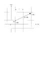
- FIG. 37 is a schematic diagram showing a modulo operation according to the prior art.
- a modulation symbol P11 to which a code P11 is attached indicates a modulation symbol before a modulo calculation (x in Expression (1)).
- a modulation symbol P12 to which a code P12 is attached indicates a remainder symbol after a modulo calculation (x ′ in Expression (1)).
- the modulation symbol P12 after the modulo calculation is within the range of [ ⁇ / 2, ⁇ / 2] from the origin for both I-ch and Q-ch.
- a modulation symbol of a desired signal transmitted from the transmission apparatus to the reception apparatus is a desired symbol s
- a modulation symbol of interference between the transmission apparatus and the reception apparatus is an interference symbol f.
- the transmitter first subtracts the interference symbol f from the desired symbol s.
- the receiving apparatus can demodulate the received signal and receive the desired symbol s as it is.
- transmission of the interference cancellation symbol signal increases the transmission power.
- the transmission apparatus can keep the modulation symbols of the signal to be transmitted within the range of [ ⁇ / 2, ⁇ / 2] from the origin for both I-ch and Q-ch, and the signal of the interference cancellation symbol sf Compared with transmitting the signal, a signal with suppressed power can be transmitted.
- the effect of noise is ignored with the propagation path characteristic set to 1.
- the above is the communication mechanism using THP.
- DL MU-MIMO THP communication using THP for multi-user MIMO (MU-MIMO; Multi-User Multi Input Multi Output) communication
- MU-MIMO Multi-User Multi Input Multi Output
- DL MU-MIMO THP This communication technique in the downlink (DL; DownLink) from the base station apparatus to the terminal apparatus.
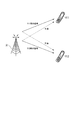
- FIG. 38 is a schematic diagram showing a wireless communication system according to the prior art.
- This figure is a diagram of a radio communication system to which DL MU-MIMO THP is applied.
- the base station apparatus X1 transmits signals to a plurality of terminal apparatuses Y11 and Y12. When these signals are transmitted to the same frequency at the same time, the signals interfere with each other (inter-user interference; Multi User Interference).
- DL MU-MIMO THP is a technique for removing this inter-user interference.
- Non-Patent Document 2 describes DL MU-MIMO THP.
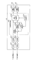
- FIG. 39 is a schematic block diagram showing the configuration of the base station device X1 according to the conventional technique.
- the filter calculation unit X131 receives channel state information (CSI) from the terminal devices Y11 and Y12, and calculates an interference coefficient and a linear filter based on the received CSI.
- the filter calculation unit X131 outputs information indicating the calculated interference coefficient and linear filter to the interference calculation unit X132 and the linear filter multiplication unit X135, respectively.
- CSI channel state information
- Interference calculation unit X132 is an interference factor indicated by the information input from the filter calculation unit X131, by multiplying the modulation symbol s 1 of the addressed terminal device Y11 input from the modulation unit X121, calculates the interference symbol f.
- the interference calculation unit X132 outputs the calculated interference symbol f to the interference subtraction unit X133.
- Interference subtraction unit X133 to the modulation symbol s 2 destined Y12 input from the modulation unit X122, subtracts the input interfering symbols f from the interference calculation section X122.
- the interference subtraction unit X133 outputs the subtracted interference cancellation symbol s 2 -f to the modulo calculation unit X134.
- the linear filter multiplication unit X135 (coefficient multiplication unit) filters the modulation symbol s 1 addressed to the terminal device Y11 input from the modulation unit X121 and the remainder symbol s 2 ′ input from the linear filter multiplication unit X135.
- the linear filter indicated by the information input from the calculation unit X131 is multiplied and output to the wireless transmission units X141 and X142.
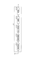
- FIG. 40 is a schematic block diagram showing the configuration of the terminal device Y1 according to the conventional technology.
- a Modu operation unit Y113 performs a Modulo operation of Expression (1) on the modulation symbol of the received signal that has been subjected to propagation path compensation, and extracts a desired symbol.
- the interference calculation unit X122 performs QR decomposition on the Hermite conjugate matrix H H of the propagation matrix H.
- QR decomposition is to decompose a matrix into a unitary matrix Q and an upper triangular matrix R. This decomposition is expressed by the following formula (2).
- the filter calculation unit X131 generates a matrix H H using CSI, and performs QR decomposition on the matrix H H.
- the filter calculation unit X131 calculates the matrix Q as a linear filter, and calculates r 12 * / r 22 * as an interference coefficient.
- r * represents the complex conjugate of r.
- the interference calculation unit X122 calculates the interference symbol f as (r 12 * / r 22 * ) s 1 .
- the modulo operation unit X134 generates the remainder symbol s 2 ′ as Mod ⁇ ⁇ s 2 ⁇ (r 12 * / r 22 * ) s 1 ⁇ , and outputs the generated remainder symbol s 2 ′ to the linear filter multiplication unit X135.
- the linear filter multiplication unit X135 generates symbols s 1 ′′ and s 2 ′′ of the following equation (3), and outputs them to the radio transmission units X141 and X142, respectively.
- a reception signal at the terminal device Y11 is set as a reception symbol y 1
- a reception signal at the terminal device Y12 is set as a reception symbol y 2 .
- y 1 and y 2 are represented by the following formula (4).
- channel compensation unit Y112 divides the r 22 * from the received symbol y 2.
- Non-Patent Document 3 discloses a case where each terminal apparatus includes a plurality of antennas and performs SU-MIOMO (Single-User Multi Input Multi Output) communication in the wireless communication system to which the DL MU-MIMO THP is applied. Is described.
- FIG. 41 is another schematic diagram showing a wireless communication system according to the prior art. This figure is a diagram of a radio communication system to which DL MU-MIMO THP is applied when each terminal apparatus performs SU-MIOMO communication.
- a base station apparatus X2 transmits a signal to each of a plurality of terminal apparatuses Y21 to Y22 using SU-MIOMO communication. When these signals are transmitted to the same frequency at the same time, the signals interfere with each other, but the interference between users is eliminated by applying DL MU-MIMO THP.
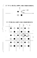
- FIG. 42 is a schematic diagram showing reception candidate points according to the prior art.
- the upper figure (a) is a figure when THP is not applied, and the lower figure (b) is a figure when THP is applied.
- FIG. 42 is a diagram when the modulation method is QPSK. In this figure, white and black circles and white and black squares indicate reception candidate points.
- the received signal point is shifted to the position of the tip of the arrow (marked with x z11, referred to as signal z11) due to the influence of noise or the like.
- the signal z11 is detected as the closest received signal point P11.
- the signal z11 is detected as the closest received signal point P22.
- the present invention has been made in view of the above points, and provides a transmission device, a reception device, a wireless communication system, a transmission control method, a reception control method, and a processor that can improve propagation characteristics.
- the present invention has been made in order to solve the above-described problems.
- the present invention provides a transmitting apparatus that includes a plurality of transmitting antennas and spatially multiplexes and transmits signals addressed to a plurality of receiving apparatuses.
- a multiplexed signal generating unit that multiplexes a signal addressed to the first receiving device that has been subjected to power suppression processing for suppressing signal power and a signal addressed to the second receiving device that is not subjected to the power suppression processing; This is a transmission device characterized by the above.
- the multiplexed signal generation unit is the first reception device based on propagation path state information with each of the plurality of reception devices. Or it is characterized by determining whether it is a 2nd receiver.
- the multiple signal generation unit multiplexes a plurality of signals addressed to the first reception device and a plurality of signals addressed to the second reception device. It is characterized by doing.
- the present invention is characterized in that, in the above transmission apparatus, the power suppression process is a remainder calculation.
- the multiple signal generation unit determines whether the reception device is a first reception device or a second reception device, and Based on the transmission mode information input from the residue switching determination unit, the remainder switching determining unit that generates and outputs transmission mode information for identifying the receiving device and the second receiving device, and the first receiving device And an adaptive remainder section for generating a signal addressed to the second receiving device.
- the remainder switching determination unit determines that the reception device is the first reception device. And determining that the receiving device is a second receiving device when interference power due to a signal addressed to another receiving device is smaller than a threshold value.
- the multiplexed signal generation unit calculates a coefficient of interference for each of the receiving apparatuses based on propagation path state information with each of the plurality of receiving apparatuses. And an interference coefficient calculated by the coefficient calculation unit and a signal addressed to another receiving device, and an interference signal generated by the signal addressed to the other receiving device.
- An interference calculating unit; and an interference subtracting unit that subtracts an interference signal generated by a signal addressed to another receiving device calculated by the interference calculating unit from a signal addressed to the receiving device, wherein the adaptive residue unit determines the residue switching decision.
- the signal destined for the first receiving device and the signal destined for the second receiving device are respectively obtained from the signals obtained by subtracting the interference signals by the interference subtracting unit. Generation And wherein the Rukoto.
- the transmission mode information generated by the remainder switching determination unit and the transmission mode information signal indicating the first reception device may be inserted into the signal. It is characterized by comprising a frame configuration unit.
- the present invention inserts a transmission mode information signal indicating the transmission mode information generated by the remainder switching determination unit and indicating the second reception apparatus into the signal. It is characterized by comprising a frame configuration unit.
- the multiple signal generation unit calculates an interference coefficient related to each of the linear filter and each of the reception devices based on propagation path state information with each of the plurality of reception devices. Based on the coefficient calculation unit to be calculated, the interference coefficient calculated by the coefficient calculation unit, and the signal destined for the other receiving device, the interference to the signal destined for the receiving device and the interference due to the signal destined for the other receiving device Input from an interference calculation unit that calculates a signal, an interference subtraction unit that subtracts an interference signal due to a signal destined for another receiving device calculated by the interference calculating unit, and a remainder switching determination unit from the signal destined for the receiving device Based on transmission mode information, an adaptive remainder unit that generates a signal addressed to the first receiving device and a signal addressed to the second receiving device from the subtracted signal subtracted by the interference subtracting unit, and the frame configuration unit
- the present invention is characterized in that, in the above transmission device, the multiple signal generation unit includes a frame configuration unit that inserts a unique reference signal of each of the reception devices into a signal addressed to the reception device. To do.
- the multiplexed signal generation unit calculates a coefficient of interference for each of the receiving apparatuses based on propagation path state information with each of the plurality of receiving apparatuses. And an interference coefficient calculated by the filter calculation unit and a signal destined for another receiving device, and an interference signal for the signal destined for the receiving device and a signal destined for the other receiving device is calculated.
- An interference calculation unit an interference subtraction unit that subtracts an interference signal based on a signal addressed to another reception device calculated by the interference calculation unit from a signal addressed to the reception device according to a predetermined order of the reception device, and an order of the reception device
- a remainder calculating unit that performs a remainder operation on a signal addressed to a first receiving device whose value is greater than a threshold value, and a signal addressed to a second receiving device whose order of the receiving device is smaller than a threshold value
- the interference subtracting unit A subtraction signal, the remainder calculation unit is characterized in that it comprises a multiplexing signal generating part for multiplexing the signal subjected to the remainder operation, a.
- a frame configuration unit for inserting a transmission mode information signal indicating that the receiving apparatus is a first receiving apparatus whose order of the receiving apparatuses is greater than a threshold value into the signal. It is characterized by providing.
- the present invention provides a frame configuration unit for inserting a transmission mode information signal indicating that the receiving apparatus is a second receiving apparatus whose order of the receiving apparatuses is smaller than a threshold value into the signal. It is characterized by providing.
- the coefficient calculation unit calculates an interference coefficient related to the linear filter and each of the receiving apparatuses based on propagation path state information with each of the plurality of receiving apparatuses.
- the multiplexed signal generation unit includes a transmission mode information signal inserted by the frame configuration unit, a signal addressed to the first reception device and a signal addressed to the second reception device generated by the adaptive remainder unit. And a coefficient multiplier for multiplying the linear filter calculated by the coefficient calculator.
- the present invention is a signal addressed to the first receiving device that has been subjected to power suppression processing for suppressing signal power in a receiving device that receives signals addressed to a plurality of spatially multiplexed receiving devices. Or a transmission mode determination unit that determines whether the signal is destined for the second reception device that does not perform the power suppression process, and adaptive demodulation that demodulates the signal based on a determination result in the transmission mode determination unit And a receiver.
- the present invention is characterized in that, in the above receiving apparatus, the power suppression process is a remainder calculation.
- the transmission mode determination unit is information included in the signal, and transmission mode information for identifying the first reception device and the second reception device. And determining whether the signal is addressed to the first receiving device or the signal addressed to the second receiving device based on the acquired transmission mode information.
- the adaptive demodulation unit determines that the transmission mode determination unit is a signal addressed to the first reception device based on the transmission mode information.
- the signal is demodulated by performing a remainder operation on the signal, and the transmission mode determination unit demodulates the signal without performing a remainder operation when it is determined that the signal is addressed to the second receiving device. To do.
- a channel separation unit that extracts a unique reference signal of each reception device from the signal, and a propagation path state based on the unique reference signal extracted by the frame separation unit
- a propagation path compensation unit that compensates the propagation path for the signal based on propagation path state information indicating the propagation path state estimated by the propagation path estimation unit.
- the transmission mode determination unit a signal addressed to the first reception device based on a unique reference signal of each of the reception devices included in the signal? Alternatively, it is determined whether the signal is addressed to the second receiving device.
- the transmission mode determination unit is an order of the reception device indicated by a position where the unique reference signal is arranged, and an interference signal is subtracted from the signal. It is determined whether the signal is addressed to the first receiving device or the signal addressed to the second receiving device based on the order.
- the transmission mode determination unit determines that the reception device is a first reception device when the order of the reception devices is an order after a threshold value.
- the receiving device is determined to be the second receiving device when the order of the receiving devices is an order before a threshold value.
- the adaptive demodulation unit performs a remainder operation on the signal when the transmission mode determination unit determines that the signal is addressed to the first reception device.
- the transmission mode determination unit determines that the signal is addressed to the second reception device, the signal is demodulated without performing a remainder operation.
- the unique reference signals are arranged in time order in the order of the reception devices, and the transmission mode determination unit includes the order of the reception devices among the unique reference signals.
- a propagation path estimation unit that selects a unique reference signal received last in the associated order and estimates a propagation path state based on the unique reference signal selected by the transmission mode determination unit, and the propagation path estimation unit includes: A propagation path compensator for performing propagation path compensation on the signal based on propagation path state information indicating the estimated propagation path state.
- the present invention provides a wireless communication system comprising: a transmission device that spatially multiplexes and transmits signals addressed to a plurality of reception devices; and a reception device that receives a signal transmitted by the transmission device.
- the apparatus generates a multiplexed signal that multiplexes a signal addressed to the first receiving apparatus that has been subjected to power suppression processing for suppressing power of a signal and a signal addressed to the second receiving apparatus that is not subjected to the power suppression process
- a transmission mode determination unit for determining whether the reception device is a signal addressed to the first reception device or a signal addressed to the second reception device; and the transmission mode determination unit
- An wireless demodulator comprising: an adaptive demodulator that demodulates the signal based on a determination result.
- the multiple signal generation unit performs power suppression processing to suppress the signal power
- a transmission control method comprising a step of multiplexing a signal addressed to the first receiving device and a signal addressed to the second receiving device not subjected to the power suppression process.
- the transmission mode determination unit performs power suppression processing that suppresses signal power.
- the present invention provides the first receiving apparatus that performs power suppression processing for suppressing signal power in a processor used in a transmitting apparatus that spatially multiplexes and transmits signals addressed to a plurality of receiving apparatuses.
- a processor comprising: a multiple signal generation unit that multiplexes a signal addressed to a signal addressed to the second receiving device that does not perform the power suppression process.
- the present invention is directed to the first receiving apparatus that performs power suppression processing for suppressing the power of a signal in a processor used in the receiving apparatus that receives signals addressed to a plurality of spatially multiplexed receiving apparatuses. Based on the determination result of the transmission mode determination unit, and the transmission mode determination unit that determines whether the signal is a signal addressed to the second reception device that does not perform the power suppression process And an adaptive demodulator that demodulates the processor.
- propagation characteristics can be improved.
- FIG. 1 is a schematic diagram showing a wireless communication system according to a first embodiment of the present invention. It is a schematic block diagram which shows the base station apparatus which concerns on this embodiment. It is a schematic block diagram which shows the structure of the multiple signal production
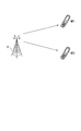
- FIG. 1 is a schematic diagram showing a radio communication system according to the first embodiment of the present invention.
- This figure is a diagram of a radio communication system to which DL MU-MIMO THP is applied.
- base station apparatus B spatially multiplexes and transmits signals addressed to a plurality of terminal apparatuses MT1 and MT2.
- whether to perform a modulo operation is switched on the signal addressed to the terminal device MT2 based on the interference power.
- the base station device B is referred to as a base station device b1
- each of the terminal devices MT1 and MT2 is referred to as a terminal device m1.
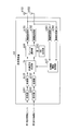
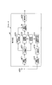
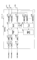
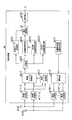
- FIG. 2 is a schematic block diagram showing the base station device b1 according to the present embodiment. This figure is a diagram in the case where the base station apparatus b1 includes two antennas that transmit signals addressed to each terminal apparatus in the same frequency band.
- the base station apparatus b1 includes encoding units b111 and b112, modulation units b121 and b122, a multiplexed signal generation unit 1b, a CRS (Common Reference Symbol) generation unit b13, a frame selection unit b14, and a radio transmission unit. b151 and b152, antennas b101 and b102, radio reception units b161 and b162, and a propagation path information acquisition unit b17.
- the encoding units b111 and b112 are input with information bits addressed to the terminal device MT1 and information bits addressed to the MT2, respectively.
- the encoding units b111 and b112 perform error correction encoding on the input information bits, and output the encoded information bits to the modulation units b121 and b122, respectively.
- the modulation units b121 and b122 modulate the input bits and output the modulated modulation symbols s 1 and s 2 to the multiplexed signal generation unit 1b, respectively.
- the multiplexed signal generation unit 1b calculates an interference symbol f generated in the radio signal addressed to the terminal device MT2 based on the channel state information (CSI; Channel State Information) input from the channel information acquisition unit b17. Multiplex signal generating unit 1b, the modulation symbol s 2 input from the modulation unit b121, item b 122, subtracts the calculated interference symbol f. In addition, the multiplexed signal generation unit 1b generates a unique reference symbol (DRS) for each terminal apparatus m1.
- DRS unique reference symbol
- the unique reference symbol and the common reference symbol to be described later are symbols for which the base station apparatus b1 and the terminal apparatus m1 store their values in advance, and are used for estimating the propagation path state and the like.
- the multiplexed signal generation unit 1b determines whether or not to perform a modulo calculation based on the CSI input from the propagation path information acquisition unit b17. If it is determined that the modulo operation is to be performed, the multiplex signal generation unit 1b performs the remainder symbol s 2 ′ after the modulo operation, the modulation symbol of the transmission mode information indicating that the modulo operation is performed (transmission mode 1), and the unique reference symbol. Are arranged in accordance with predetermined mapping information. The multiplexed signal generation unit 1b multiplies the symbols in the arranged symbol sequence by a linear filter and outputs the result to the frame selection unit b14.
- the multiple signal generation unit 1b transmits the interference cancellation symbol s 2 -f, the modulation symbol of the transmission mode information indicating that the modulo operation is not performed (transmission mode 2), and the unique symbol. Reference symbols are arranged according to predetermined mapping information.
- the multiplexed signal generation unit 1b multiplies the symbols in the arranged symbol sequence by a linear filter and outputs the result to the frame selection unit b14. Details of the processing performed by the multiplexed signal generation unit 1b will be described later.
- the CRS generation unit b13 generates a common reference symbol (CRS) for each antenna and outputs it to the frame selection unit b14.
- the frame selection unit b14 arranges the common reference symbols of the antennas b101 and b102 input from the CRS generation unit b13 in the frequency band according to the mapping information, and sends them to the radio transmission unit b151 for each predetermined transmission time unit (frame). Output.
- the frame selection unit b14 arranges the symbol sequence addressed to the terminal devices MT1 and MT2 input from the multiplexed signal generation unit 1b in a frequency band for transmitting signals to the terminal devices MT1 and MT2 according to the mapping information.
- the frequency bands in which the symbol strings of the terminal devices MT1 and MT2 are arranged are the same frequency band.
- the frame selection unit b14 outputs the signal arranged in the frequency band to the wireless transmission unit b152 for each predetermined transmission time unit (frame).
- the radio transmission units b151 and b152 respectively receive a signal addressed to the terminal device MT1 and a signal addressed to MT2 from the frame selection unit b14.
- the radio transmitters b151 and b152 perform digital / analog conversion on the input signal, and up-convert the converted signal to a carrier frequency.
- the radio transmission units b151 and b152 transmit the up-converted radio signals (see FIGS. 4 and 5) via the antennas b101 and b102, respectively.
- mapping information used by the frame selection unit b14, the encoding schemes in the encoding units b111 and b112, and the modulation schemes in the modulation units b121 and b122 are determined by the base station device b1 by the terminal device m1 (in this embodiment, the terminal device). Notification to MT1, MT2) in advance.
- the radio receiving units b161 and b162 receive radio signals from the terminal devices MT1 and MT2 via the antennas b101 and b102, respectively.
- the radio reception units b161 and b162 down-convert the received radio signal into a baseband band and perform analog / digital conversion on the down-converted signal.
- the radio reception units b161 and b162 output the converted signals to the propagation path information acquisition unit b17.
- the propagation path information acquisition unit b17 demodulates the signals input from the radio reception units b161 and b162.
- the propagation path information acquisition unit b17 is CSI indicating the propagation path state between the base station apparatus, the terminal apparatuses MT1 and MT2, and the antennas b101 and b102, and is estimated by the terminal apparatuses MT1 and MT2 from the demodulated information. Extract CSI.
- the propagation path information acquisition unit b17 outputs the extracted CSI to the multiple signal generation unit 1b.
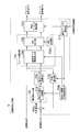
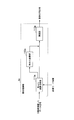
- FIG. 3 is a schematic block diagram showing the configuration of the multiplexed signal generator 1b according to the present embodiment.
- a multiplex signal generator 1b includes a linear filter calculator 111b, an interference calculator 112b, an interference subtractor 113b, a modulo operation switching determination unit 114b, an adaptive modulo unit 12b, a frame configuration unit 13b, and a linear filter multiplier.
- the adaptive modulo unit 12b (adaptive remainder unit) includes a modulo arithmetic switching unit 121b and a modulo arithmetic unit 122b.
- the frame configuration unit 13b includes a transmission mode information insertion unit 131b, a DRS generation unit 132b, and a DRS insertion unit 133b.
- the linear filter calculation unit 111b receives CSI.
- the linear filter calculation unit 111b generates a propagation matrix H from the input CSI.
- the linear filter calculation unit 111b performs QR decomposition on the Hermitian conjugate matrix H H of the generated propagation matrix H to calculate an interference coefficient (r 12 * / r 22 * ) and a linear filter (matrix Q).
- QR decomposition is to decompose a matrix into a unitary matrix Q and an upper triangular matrix R, and this QR decomposition is expressed by the following equation (2).
- R * represents the complex conjugate of r.
- h 11 and h 12 are propagation path estimation values between the antenna b101 and the terminal apparatuses MT1 and MT2, respectively, and h 21 and h 22 are propagation paths between the antenna b201 and the terminal apparatuses MT1 and MT2, respectively.
- Estimated value (complex gain).
- the propagation path estimation value is information included in the CSI.
- the linear filter calculation unit 111b outputs information indicating the calculated interference coefficient to the interference calculation unit 112b and the modulo calculation switching determination unit 114b. Further, the linear filter calculation unit 111b outputs information indicating the linear filter to the linear filter multiplication unit 141b.
- Interference calculation section 112b is input modulation symbols s 1.
- the interference calculation unit 112b outputs the calculated interference symbol f to the interference subtraction unit 113b.
- Interference subtraction unit 113b is input to modulation symbol s 2.
- the interference subtraction unit 113b outputs the interference cancellation symbol s 2 -f after the subtraction to the modulo arithmetic switching unit 121b.
- the modulo calculation switching determination unit 114b calculates the interference power P expressed by the following equation (7) by squaring the interference coefficient input from the linear filter calculation unit 111b.
- Modulo arithmetic switching determining unit 114b when the calculated interference power P is greater than the threshold P 0 a predetermined determines that performs Modulo operation. In this case, the modulo calculation switching determination unit 114b outputs transmission mode information indicating that the modulo calculation is performed (transmission mode 1) to the transmission mode information insertion unit 131b and the modulo calculation switching unit 121b. On the other hand, when the calculated interference power P is equal to or less than the predetermined threshold value P 0 , the modulo calculation switching determination unit 114b determines not to perform the modulo calculation. In this case, the modulo calculation switching determination unit 114b outputs transmission mode information indicating that the modulo calculation is not performed (transmission mode 2) to the transmission mode information insertion unit 131b and the modulo calculation switching unit 121b.
- the modulo calculation switching unit 121b transmits the interference cancellation symbol s 2 -f input from the interference subtraction unit 113b to the modulo calculation unit 122b. Output.
- the modulo calculation switching unit 121b uses the interference cancellation symbol s 2 -f input from the interference subtraction unit 113b as the transmission mode information. It outputs to the insertion part 131b.
- the modulo operation unit 122b (residue operation unit) performs a modulo operation on the interference cancellation symbol s 2 -f input from the modulo operation switching unit 121b.
- the modulo operation is expressed by the following equation (8).
- Mod ⁇ (x) represents a modulo operation
- x and x ′ represent modulation symbols before and after the modulo operation, respectively.
- J is an imaginary unit
- Re (x) represents the real part of x
- Im (x) represents the imaginary part of x.
- floor (x) represents the maximum integer not exceeding x.
- the transmission mode information insertion unit 131b modulates the transmission mode information input from the modulo calculation switching determination unit 114b.
- the transmission mode information insertion unit 131b receives the remainder symbol s 2 ′ input from the modulo arithmetic unit 122b or the interference cancellation symbol s 2 -f input from the modulo arithmetic switching unit 121b, and the modulation symbol of the modulated transmission mode information Are arranged in the order of time indicated by the mapping information (a symbol string addressed to the terminal device MT2).
- the transmission mode information insertion unit 131b arranges the modulation symbol s 1 input from the modulation unit b121 and the modulation symbols of the transmission mode information indicating the transmission mode 2 in the order indicated by the mapping information (addressed to the terminal device MT1) Symbol column).
- the transmission mode information insertion unit 131b outputs the symbol string for each arranged terminal apparatus m1 to the DRS insertion unit 133b.
- the DRS generator 132b generates a unique reference symbol for each terminal device m1 (terminal devices MT1 and MT2 in the present embodiment).
- the DRS generation unit 132b outputs the generated unique reference symbol for each terminal device m1 to the DRS insertion unit 133b.
- the DRS insertion unit 133b inserts the unique reference symbol for each terminal device m1 input from the DRS generation unit 132b into the symbol sequence of the terminal device m1 and inserted from the transmission mode information insertion unit 131b.
- the DRS insertion unit 133b inserts the unique reference symbol at the time indicated by the mapping information.
- the DRS insertion unit 133b outputs a symbol string (frame) for each terminal device m1 into which the unique reference symbol is inserted, to the linear filter multiplication unit 141b.
- Linear filter multiplying unit 141b is a symbol to be transmitted at the same time, a symbol S 1 of symbol sequence of the terminal device MT1 input from DRS insertion portion 133b, a symbol S 2 for symbol sequence of the terminal device MT2, the Generate a combined vector.
- the linear filter multiplication unit 141b multiplies the generated vector by the linear filter indicated by the information input from the linear filter calculation unit 111b. Symbols S 1 ′′ and S 2 ′′ multiplied by the linear filter are expressed by the following equation (9).
- the linear filter multiplication unit 141b outputs the symbol sequences including the symbols S 1 ′′ and S 2 ′′ to the frame selection unit b14 as symbol sequences transmitted by the antenna b101 and the antenna b102, respectively.
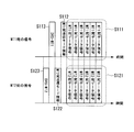
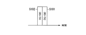
- FIG. 4 is a schematic diagram illustrating an example of a radio signal transmitted by the base station apparatus b1 according to the present embodiment.
- the horizontal axis represents the time axis.
- this figure shows a radio signal transmitted in the same frequency band divided into radio signals for each terminal device (a radio signal addressed to the terminal device MT1 and a radio signal addressed to the terminal device MT2).
- a radio signal addressed to the terminal device MT1 includes a signal S111 of the modulation symbol s 1 (data signal addressed to MT1), a signal S112 of transmission mode information of the terminal device MT1 (in this embodiment, transmission mode 2), and a terminal This signal includes the unique reference symbol signal S113 (DRS-MT1) of the device MT1.
- the radio signal addressed to the terminal device MT2 includes a signal of the remainder symbol s 2 ′ or a signal S121 of the interference cancellation symbol s 2 -f (data signal addressed to MT2), a signal S122 of transmission mode information of the terminal device MT2, and the terminal device This is a signal including the MT2 unique reference symbol signal S123 (DRS-MT2).
- signals S111 and S121 are transmitted at the same time, that is, they are spatially multiplexed.
- FIG. 4 shows that the signals S112, S113, S122, and S123 are not transmitted at the same time, that is, are time-division multiplexed.
- FIG. 5 is a schematic diagram illustrating another example of a radio signal transmitted by the base station apparatus b1 according to the present embodiment.
- This figure is a schematic diagram showing an example of a radio signal including CRS for the terminal apparatus m1 to estimate the propagation path.
- the base station apparatus b1 transmits the radio signal shown in FIG.
- the base station apparatus b1 transmits the radio signal shown in FIG.
- the horizontal axis indicates the time axis.
- This figure also shows common reference symbol signals S101 and S102 (CRS-TX1, CRS-TX2) among radio signals transmitted in the same frequency band.
- FIG. 6 is a schematic block diagram showing the configuration of the terminal device m1 according to the present embodiment. This figure is a diagram when the terminal device m1 has one antenna. 6, the terminal device m1 includes an antenna m101, a radio reception unit m111, a frame separation unit m121, a propagation path estimation unit m122, a propagation path compensation unit m123, a transmission mode acquisition unit m124, an adaptive demodulation unit 1m, a decoding unit m124, a propagation A road state information generation unit m131, a frame configuration unit m132, and a wireless transmission unit m141 are configured.
- the terminal device m1 includes an antenna m101, a radio reception unit m111, a frame separation unit m121, a propagation path estimation unit m122, a propagation path compensation unit m123, a transmission mode acquisition unit m124, an adaptive demodulation unit 1m, a decoding unit m124, a propagation A road state information generation unit m
- the radio reception unit m111 receives a radio signal from the base station apparatus b1 via the antenna m101.
- the radio reception unit m111 down-converts the received radio signal to the baseband band, and performs analog / digital conversion on the down-converted signal.
- the wireless reception unit m111 outputs the converted signal to the frame separation unit m121.
- the frame separation unit m121 separates the signal addressed to itself from the signal input from the wireless reception unit m111 based on the mapping information notified in advance from the base station device b1.
- the frame separation unit m121 outputs the signal of the common reference symbol among the separated signals and the signal of the unique reference symbol of the own device to the propagation path estimation unit m122.
- the frame separation unit m121 outputs a data signal (signals S111 and S121 in the example of FIG. 4) addressed to the own device among the separated signals to the propagation path compensation unit m123.
- y 1 modulation symbol of the data signal in the terminal device MT1 the received symbol y 2 modulation symbols of the data signal in the terminal device MT2 is represented by the following formula (10) or (11).
- Equation (10) is a case where the transmission mode information indicates “transmission mode 1”
- equation (11) is a case where the transmission mode information indicates “transmission mode 2”.
- Equation (10) indicates that the symbols S 1 and S 2 are multiplied by a linear filter, so that the received symbols y 1 and y 2 become symbols when the propagation matrix is the matrix RH .
- the frame separation unit m121 outputs a signal of transmission mode information among the separated signals to the transmission mode acquisition unit m124.
- the propagation path estimation unit m122 estimates the propagation path state from each antenna of the base station apparatus b1 based on the common reference symbol signal and the unique reference symbol signal input from the frame separation unit m121.
- the propagation path estimation unit m112 outputs the CSI indicating the propagation path state estimated based on the common reference symbol signal and the unique reference symbol signal to the propagation path state information generation unit m131 and the propagation path compensation unit m123, respectively.
- the propagation path compensation unit m123 Based on the CSI input from the propagation path estimation unit m122, the propagation path compensation unit m123 performs propagation path compensation on the data signal addressed to the own apparatus input from the frame separation unit m121.
- the propagation path compensation unit m123 outputs a data signal addressed to the own apparatus extracted by performing propagation path compensation to the adaptive modulation unit 1m.
- the transmission mode acquisition unit m124 acquires the transmission mode information by demodulating the transmission mode information signal input from the frame separation unit m121.
- the transmission mode acquisition unit m124 outputs the acquired transmission mode information to the adaptive demodulation unit 1m.
- the adaptive demodulation unit 1m demodulates the data signal input from the propagation path compensation unit m123 based on the transmission mode information input from the transmission mode acquisition unit m124.
- the adaptive demodulation unit 1m outputs the demodulated bits to the decoding unit m124.
- the decoding unit m124 decodes and outputs the bits input from the adaptive demodulation unit 1m.
- the propagation path state information generation unit m131 modulates the CSI input from the propagation path compensation unit m123, and outputs the modulated signal to the frame configuration unit m132.
- the frame configuration unit m132 arranges the signal input from the propagation path state information generation unit m131 in the frequency band for transmitting the signal to the base station apparatus b1.
- the frame configuration unit m132 outputs a signal arranged in the frequency band to the wireless transmission unit m141 for each predetermined transmission time unit (frame).
- the wireless transmission unit m141 performs digital / analog conversion on the signal input from the frame configuration unit m132, and upconverts the converted signal to a carrier frequency.
- the wireless transmission unit m141 transmits the upconverted wireless signal via the antenna m101.
- FIG. 7 is a schematic block diagram showing the configuration of the adaptive demodulation unit 1m according to the present embodiment. This figure shows the configuration of the adaptive demodulator 1m in FIG.
- the adaptive demodulation unit 1m includes a modulo calculation switching unit 111m, a modulo calculation unit 112m, and a demodulation unit 113m.
- the modulo calculation switching unit 111m receives a data signal and transmission mode information.
- the modulo calculation switching unit 111m outputs the input data signal to the modulo calculation unit 112m.
- the modulo calculation switching unit 111m outputs the input data signal to the demodulation unit 113m.
- Modulo arithmetic unit 112m to the modulation symbols z 2 of the input data signals from the Modulo arithmetic switching unit 111m, by performing Modulo operation to extract the desired symbol s 2 (see equation (5)).
- Modulo arithmetic unit 112m outputs the extracted data signal of a desired symbol s 2 to the demodulator 113m.
- the demodulation unit 113m demodulates the data signal input from the modulo operation unit 112m.
- the demodulator 113m outputs the demodulated bits (hard decision result) or soft estimation values (soft estimation result).
- the multiplexed signal generation unit 1b performs a signal addressed to the terminal device MT2 that has performed the modulo operation and a signal addressed to the terminal device MT1 that does not perform the modulo operation. And multiplex. Further, the transmission mode acquisition unit m124 acquires transmission mode information from the received signal, and determines whether the signal is addressed to a terminal device that has performed a modulo operation or a signal that is addressed to a terminal device that does not perform a modulo operation. To do. Based on this determination result, the adaptive demodulator 1m demodulates the signal by performing a modulo operation.
- the radio communication system multiplexes a signal with low interference power and a signal with high interference power, performs a modulo operation on a signal with high interference power, and performs a modulo operation on a signal with low interference power.
- Signals can be multiplexed without performing calculations. That is, in this embodiment, the wireless communication system can prevent reception detection points from increasing and signal detection performance from deteriorating, can perform communication with high power efficiency, and can improve propagation characteristics. .
- the interference signal for the signal addressed to the terminal apparatus MT2 may be increased because the interference signal for the signal addressed to the terminal apparatus MT1 is eliminated by multiplication of the linear filter.
- the modulo calculation is performed when the interference signal becomes large, it is possible to perform communication with high power efficiency by reducing the transmission power.
- the multiplexed signal generation unit 1b calculates the interference power due to the signal of the terminal device MT1 based on the propagation path state information with each of the plurality of terminal devices MT1 and MT2. Also, multiplexing signal generating unit 1b, the calculated interference power P is determined to carry out the Modulo operation on a signal addressed to the mobile station MT2 is larger than the threshold value P 0, the calculated interference power P is when the threshold value P 0 is smaller than It is determined that the modulo operation is not performed on the signal addressed to the terminal device MT2.
- the radio communication system prevents the reception candidate points from increasing and the signal detection performance from deteriorating when the interference power is low, and has high power efficiency when the interference power is high. Communication can be performed and propagation characteristics can be improved.
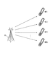
- FIG. 8 is a schematic diagram showing a radio communication system according to the second embodiment of the present invention.
- the base station apparatus B transmits signals to N terminal apparatuses MT1 to MTN.
- the base station apparatus B is referred to as a base station apparatus b2.
- the terminal device m1 according to the present embodiment performs channel compensation based on channel state information with the N antennas of the base station device B.
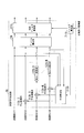
- FIG. 9 is a schematic block diagram showing the base station device b2 according to the present embodiment. This figure is a diagram in the case where N antennas for transmitting signals addressed to each terminal apparatus in the same frequency band are provided.
- base station apparatus b2 encoding units b111 to b11N, modulating units b121 to b12N, multiplexed signal generating unit 2b, CRS generating unit b23, frame selecting unit b24, radio transmitting units b151 to b15N, antennas b101 to b10N, radio The reception unit b161 to b16N, a frame separation unit b28, and a propagation path information acquisition unit b27 are configured.
- Information bits addressed to the terminal device MTk are respectively input to the code part b11k.
- the encoding unit b11k performs error correction encoding on the input information bits and outputs the information bits to the modulating unit b12k.
- Modulation unit b12k modulates the bits input and output respectively, the modulation symbol s k modulated into multiple signal generator 2b.
- the multiplexed signal generation unit 2b calculates an interference symbol fk generated in the radio signal addressed to the terminal device MTk based on the CSI input from the propagation path information acquisition unit b27. Multiplexing signal generation unit 2b, the modulation symbol s k input from the modulation unit B12k, subtracts the calculated interference symbol f k. Moreover, the multiplexed signal generation unit 2b generates a unique reference symbol for each terminal device m1.
- the multiplexed signal generation unit 2b determines whether or not to perform a modulo calculation for each terminal device MTk based on the CSI input from the propagation path information acquisition unit b27. When it is determined that the modulo operation is to be performed, the multiplexed signal generation unit 2b modulates the transmission mode information indicating that the modulo operation is performed on the remainder symbol s k ′ after the modulo operation and the symbol addressed to the terminal device MTk (transmission mode 1). Symbols and unique reference symbols are arranged according to predetermined mapping information. The multiplexed signal generation unit 2b multiplies the symbols of the arranged symbol strings by a linear filter and outputs the result to the frame selection unit b24.
- the multiplexed signal generation unit 2b indicates that the modulo operation is not performed on the interference cancellation symbol s k -f k and the symbol addressed to the terminal device MTk (transmission mode 2).
- Information modulation symbols and unique reference symbols are arranged according to predetermined mapping information.
- the multiplexed signal generation unit 1b multiplies the symbols in the arranged symbol sequence by a linear filter and outputs the result to the frame selection unit b24.
- the CRS generation unit b23 generates a common reference symbol (CRS) for each antenna and outputs it to the frame selection unit b24.
- the frame selection unit b24 arranges the common reference symbol of the antenna b10k input from the CRS generation unit b13 in a predetermined frequency band according to the mapping information. Further, the frame selection unit b24 arranges the symbol sequence addressed to the terminal device MTk input from the multiplexed signal generation unit 2b in the frequency band for transmitting a signal to the terminal device MTk, according to the mapping information.
- the frame selection unit b24 outputs the signals arranged in the frequency band to the radio transmission unit b15k for each predetermined transmission time unit (frame).
- a signal for each antenna b10k is input from the frame selection unit b24 to the wireless transmission unit b15k.
- the wireless transmission unit b15k performs digital / analog conversion on the input signal, and up-converts the converted signal to a carrier frequency.
- the radio transmission unit b15k transmits the upconverted radio signals via the antenna b10k.
- Each of the radio reception units b16k receives a radio signal from the terminal device MTk via the antenna b10k.
- the radio reception unit b16k down-converts the received radio signal to the baseband band, and performs analog / digital conversion on the down-converted signal.
- the wireless reception unit b16k outputs the converted signal to the frame separation unit b28.
- the frame separation unit b28 separates the signal input from the wireless reception unit b16k for each terminal device MTk that is a transmission source.
- the frame separation unit b28 outputs the separated CSI for each terminal device MTk to the propagation path information acquisition unit b27.
- the propagation path information acquisition unit b27 demodulates the signal input from the frame separation unit b28.
- the propagation path information acquisition unit b27 extracts CSI indicating the propagation path state between each terminal device MTk and each base station apparatus antenna b10k from the demodulated information and estimated by each terminal apparatus MTk.
- the propagation path information acquisition unit b27 outputs the extracted CSI to the multiplexed signal generation unit 2b.
- FIG. 10 is a schematic block diagram showing the configuration of the multiple signal generator 2b according to this embodiment.
- a multiplex signal generator 2b includes a linear filter calculator 211b, an interference calculator 212b, interference subtractors 113b-2 to 113b-N, a modulo operation switching determination unit 214b, and adaptive modulo units 12b-2 to 12b-N.
- the linear filter calculation unit 211b receives CSI.
- the linear filter calculation unit 111b generates a propagation matrix H from the input CSI.
- Linear filter calculator 211b is the Hermitian conjugate matrix H H of the generated propagation matrix H to QR decomposition to calculate the linear filter (matrix Q).
- the linear filter calculation unit 211b generates a diagonal matrix A obtained by extracting a diagonal component from the calculated Hermitian conjugate matrix RH of the matrix R.
- a ⁇ 1 represents an inverse matrix of A
- I represents a unit matrix.
- a ⁇ 1 is multiplied by RH in order to calculate the interference component included in the signal after channel compensation is performed by the terminal device MTk (in the first embodiment).
- r 22 * I is subtracted from A ⁇ 1 RH to remove the component of the data signal addressed to the terminal device MTk.
- the linear filter calculation unit 211b sets the (l, x) component of the calculated interference coefficient matrix B as the interference coefficient B lx , and outputs information indicating the interference coefficient to the interference calculation unit 212b and the modulo calculation switching determination unit 214b. Further, the linear filter calculation unit 211b outputs information indicating the linear filter to the linear filter multiplication unit 241b.
- a symbol input from adaptive modulo section 12b-k is set as transmission data symbol ⁇ k .
- the interference calculation unit 212b calculates an interference symbol f k represented by the following equation (12) based on the information input from the linear filter calculation unit 211b and the input symbol.
- the interference calculation unit 212b outputs the calculated interference symbols f k to the interference subtraction units 113b-k, respectively.
- the interference subtraction unit 113b-k subtracts the interference symbol f k input from the interference calculation unit 212b from the input modulation symbol s k .
- the interference subtraction unit 113b-k outputs the subtracted interference cancellation symbol s k -f k to the adaptive modulo unit 12b-k.
- the modulo calculation switching determination unit 214b calculates the interference power P k represented by the following equation (13) based on the interference coefficient indicated by the information input from the linear filter calculation unit 211b (referred to as interference power calculation processing).
- the modulo calculation switching determination unit 214b determines that the modulo calculation is performed on the symbol string addressed to the terminal device MTk. In this case, the modulo calculation switching determination unit 214b transmits the transmission mode information addressed to the terminal device MTk and indicating the modulo calculation (transmission mode 1) to the frame configuration unit 23b and the adaptive modulo unit 12b-k. Output to.
- the modulo calculation switching determination unit 214b determines not to perform the modulo calculation on the symbol string addressed to the terminal device MTk. In this case, the modulo operation switching determination unit 214b transmits the transmission mode information that is the transmission mode information addressed to the terminal device MTk and indicates that the modulo operation is not performed (transmission mode 2), the frame configuration unit 23b, and the adaptive modulo unit 12b- output to k.
- the adaptive modulo unit 12b-k outputs the calculated remainder symbol s k ′ as the transmission data symbol ⁇ k to the frame configuration unit 23b as a symbol addressed to the terminal device MTk.
- the adaptive modulo unit 12b-k cancels the interference input from the interference subtracting unit 113b-k when the transmission mode information addressed to the terminal device MTk input from the modulo arithmetic switch determining unit 214b indicates “transmission mode 2”.
- the symbol s k -f k is output as a transmission data symbol ⁇ k to the frame configuration unit 23b as a symbol addressed to the terminal device MTk.
- the frame configuration unit 23b modulates the transmission mode information input from the modulo calculation switching determination unit 214b.
- the frame configuration unit 23b generates a unique reference symbol for each terminal device m1.
- the frame configuration unit 23b transmits the transmission data symbol ⁇ k input from the adaptive modulo unit 12b-k, the modulation symbol of the modulated transmission mode information, and the generated unique reference symbol of the terminal device MTk in the time order indicated by the mapping information. Arrange (symbol string addressed to terminal device MTk).
- the frame configuration unit 23b outputs a symbol string (frame) for each arranged terminal apparatus m1 to the linear filter multiplication unit 241b.
- the combined vector is multiplied by the linear filter indicated by the information input from the linear filter calculation unit 211b.
- the linear filter multiplication unit 241b outputs the symbol sequence including the symbol S k ′′ to the frame selection unit b14 as a signal to be transmitted by the antenna b10k.
- FIG. 11 is a schematic block diagram showing the configuration of the adaptive modulo unit 12b-k according to the present embodiment.
- the adaptive modulo unit 12b-k includes a modulo arithmetic switching unit 121b-k and a modulo arithmetic unit 122b-k.
- the modulo calculation switching unit 121b-k when the transmission mode information addressed to the terminal device MTk input from the modulo calculation switching determination unit 214b indicates “transmission mode 1,” the interference cancellation symbol input from the interference subtraction unit 113b-k.
- s k -f k is output to the modulo arithmetic unit 122b-k.
- the adaptive modulo unit 12b-k cancels the interference input from the interference subtracting unit 113b-k when the transmission mode information addressed to the terminal device MTk input from the modulo arithmetic switch determining unit 214b indicates “transmission mode 2”.
- the symbol s k -f k is output to the transmission mode information insertion unit 231b.
- the modulo operation unit 122b-k performs a modulo operation on the interference cancellation symbols s k -f k input from the modulo operation switching unit 121b-k.
- FIG. 12 is a schematic block diagram showing the configuration of the frame configuration unit 23b according to this embodiment.
- the frame configuration unit 23b includes a transmission mode information insertion unit 231b, a DRS generation unit 232b, and a DRS insertion unit 233b.
- the transmission mode information insertion unit 231b modulates the transmission mode information input from the adaptive modulo unit 12b-k.
- the transmission mode information insertion unit 231b, the transmission mode information insertion unit 231b, and the transmission data symbol ⁇ k input from the modulo operation unit 122b-k and the modulation symbols of the modulated transmission mode information are arranged in the time order indicated by the mapping information. Arrange (symbol string addressed to terminal device MT2).
- the transmission mode information insertion unit 231b arranges the modulation symbol s 1 input from the modulation unit b121 and the modulation symbols of the transmission mode information indicating the transmission mode 2 in order of time indicated by the mapping information (addressed to the terminal device MT1) Symbol column).
- the transmission mode information insertion unit 231b outputs the symbol string for each arranged terminal apparatus m1 to the DRS insertion unit 233b.
- the DRS generator 232b generates a unique reference symbol for each terminal device m1.
- the DRS generation unit 232b outputs the generated unique reference symbol for each terminal device m1 to the DRS insertion unit 233b.
- the DRS insertion unit 233b inserts the unique reference symbol for each terminal device m1 input from the DRS generation unit 232b into the symbol sequence of the terminal device m1 and the symbol sequence inserted from the transmission mode information insertion unit 231b.
- the DRS insertion unit 233b inserts the unique reference symbol at the time indicated by the mapping information.
- the DRS insertion unit 233b outputs a symbol string (frame) for each terminal device m1 into which the unique reference symbol is inserted, to the linear filter multiplication unit 241b.
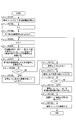
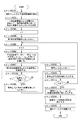
- FIG. 13 is a flowchart showing the operation of the multiplexed signal generator 2b according to this embodiment.
- the linear filter calculation unit 211b calculates a linear filter (matrix Q) and an interference coefficient matrix B, and inputs the interference coefficient information to the modulo calculation switching determination unit 214b and the interference calculation unit 212b. Thereafter, the process proceeds to step S12.
- the modulo calculation switching determination unit 214b calculates the interference power P k based on the interference coefficient information, and determines whether or not to perform the modulo calculation on the symbol addressed to each terminal apparatus MTk. Further, the modulo calculation switching determination unit 214b generates transmission mode information representing the determination result.
- step S103 The interference calculation unit 212b substitutes 1 for the variable k. Thereafter, the process proceeds to step S104.
- interference calculation section 212b is a modulation symbol s 1 addressed to the mobile station MT1 to transmit data symbols [nu 1. Thereafter, the process proceeds to step S105.
- Step S105 The interference calculation unit 212b adds 1 to k. Thereafter, the process proceeds to step S106.
- the interference calculation unit 212b uses the interference coefficient matrix B calculated in step S101 and the transmission data symbols ⁇ 1 to ⁇ k ⁇ 1 addressed to the terminal devices MT1 to (k ⁇ 1) to be addressed to the terminal device MTk.
- An interference symbol f k generated in the radio signal is calculated (see equation (12)).
- the process proceeds to step S107.
- Step S107 The interference subtraction unit 113b-k calculates the interference cancellation symbol s k -f k by subtracting the interference symbol f k calculated in step S106 from the modulation symbol s k addressed to the terminal device MTk. Thereafter, the process proceeds to step S108.
- Step S108 The modulo calculation switching unit 121b-k determines whether or not the transmission mode information addressed to the terminal device MTk generated in step S12 indicates “transmission mode 1”. When the transmission mode information addressed to the terminal device MTk indicates “transmission mode 1” (Yes), the process proceeds to step S109. On the other hand, when the transmission mode information addressed to the terminal device MTk indicates other than “transmission mode 1” (No), the process proceeds to step S110.
- Step S109 The modulo calculator 122b-k performs a modulo calculation on the interference cancellation symbols s k -f k calculated in step S108. The modulo calculator 122b-k sets the interference cancellation symbol s k -f k as the transmission data symbol ⁇ k .
- step S111 The modulo operation unit 122b-k sets the modulation symbol sk as the transmission data symbol ⁇ k . Then, it progresses to step S111.
- Step S111 The modulo calculation unit 122b-k inputs ⁇ k substituted in Step S109 or S110 to the interference calculation unit 212b. Thereafter, the process proceeds to step S112.
- Step S113 The frame configuration unit 23b receives the transmission data symbols ⁇ 1 to ⁇ N generated in step S104, S109, or S110. Thereafter, the process proceeds to step S114.
- Step S114 The frame configuration unit 23b inserts the transmission mode information and the unique reference symbol into the symbol string. Thereafter, the process proceeds to step S115.
- Step S115 The linear filter multiplication unit 241b multiplies the vector obtained by combining the transmission data symbols ⁇ k by a linear filter (see Expression (14)). Thereafter, the operation is terminated.
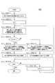
- FIG. 14 is a flowchart showing an example of the operation of the interference power calculation process according to the present embodiment.
- This figure shows the processing operation in step S12 of FIG. (Step S12-1) Modulo arithmetic switching determining unit 214b, the power of the modulation symbol s 1 addressed to the mobile station MT1 to transmit power Qs.
- Qs is an average power obtained by averaging the power of symbols obtained by modulating the data signal.
- Step S12-2 (Step S12-2)
- the modulo calculation switching determination unit 214b substitutes 2 for the variable k. Thereafter, the process proceeds to step S12-3.
- Modulo arithmetic switching determining unit 214b is a Qs calculated transmission power T 1 in step S12-1.
- Step S12-4 Modulo arithmetic switching determination unit 214b determines the interference power P k calculated is whether a threshold value P 0 is larger than in the step S 12 - 3. If it is determined that the interference power P k is greater than the threshold value P 0 (Yes), the process proceeds to step S12-5. On the other hand, when it is determined that the interference power P k is equal to or less than the threshold value P 0 (No), the process proceeds to step S12-7. (Step S12-5) The modulo calculation switching determination unit 214b determines the transmission mode information addressed to the terminal device MTk to “transmission mode 1”. Thereafter, the process proceeds to step S12-6.
- Modulo arithmetic switching determination unit 214b has a Q M and transmit power T k.
- Q M is the average power of the remainder symbol s k ′ and is [ ⁇ / 2, ⁇ / 2], Q ⁇ ch as I-ch centered on the origin on the signal point plane (see FIG. 37). The power when assuming that the signals are distributed with equal probability at signal points included in [ ⁇ / 2, ⁇ / 2].
- Step S12-7 The modulo calculation switching determination unit 214b determines the transmission mode information addressed to the terminal device MTk to “transmission mode 2”. Thereafter, the process proceeds to step S12-8.
- Step S12-8 Modulo arithmetic switching determination unit 214b has a Qs + P k to the transmit power T k.
- Qs + P k represents the average power of the interference cancellation symbol s k -f k .
- step S12-10 The modulo calculation switching determination unit 214b adds 1 to k. Thereafter, the process returns to step S12-3.
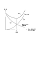
- FIG. 15 is an explanatory diagram for explaining a threshold value P 0 according to the present embodiment.
- the horizontal axis indicates the interference power
- the vertical axis indicates the error rate.
- a curve L11 with a symbol L11 indicates the relationship between the interference power and the error rate when the modulo calculation is not performed.
- Curve L11 is the probability of performing the Modulo operation threshold P 0 is decreased is increased, increasing the Modulo Loss due to Modulo operation, indicating that an error will be more likely to occur.
- a curve L1 with a symbol L1 is the sum of the curves L11 and L12. In the present embodiment, the minimum value in the curve L1 to a threshold P 0.
- the multiplexed signal generation unit 2b is a signal addressed to the terminal device MTk in “transmission mode 1” and subjected to the modulo operation, and the terminal device MTk in “transmission mode 2”. And a signal to which the modulo operation is not performed.
- the radio communication system multiplexes a signal with low interference power and a signal with high interference power, performs a modulo operation on a signal with high interference power, and performs a modulo operation on a signal with low interference power. Signals can be multiplexed without performing calculations.
- an interference signal with respect to a signal addressed to the terminal device MTk may increase due to multiplication of a linear filter.
- the modulo calculation is performed when the interference signal becomes large, it is possible to perform communication with high power efficiency by reducing the transmission power.
- the base station apparatus b2 determines whether or not to perform a modulo calculation based on the interference power Pk . In the present embodiment, it is determined whether or not to perform the modulo calculation based on the order of performing the process of subtracting interference (referred to as the interference removal order; the same as the order of the terminal devices MTk (terminal number k)). Since the schematic diagram showing the wireless communication system according to the present embodiment is the same as that of the second embodiment (FIG. 8), description thereof is omitted.
- the base station apparatus B according to the present embodiment is referred to as a base station apparatus b3.
- the terminal device m1 according to the present embodiment performs channel compensation based on channel state information with the N antennas of the base station device B.
- FIG. 16 is a schematic block diagram showing the configuration of the base station apparatus b3 according to the third embodiment of the present invention.
- the multiplexed signal generating unit 3b is different.
- FIG. 17 is a schematic block diagram showing the configuration of the multiplexed signal generation unit 3b according to this embodiment.
- the multiplexed signal generator 3b includes an adaptive modulo unit 12b-2 ⁇ 12b- (K-1) (K is a natural number greater than or equal to 3) and the modulo operation switching determination unit 214b is not provided, and the modulo operation units 122b-K to 122b are replaced with the adaptive modulo units 12b-K to b12-N.
- K-1 K is a natural number greater than or equal to 3
- the modulo operation switching determination unit 214b is not provided
- the modulo operation units 122b-K to 122b are replaced with the adaptive modulo units 12b-K to b12-N.
- the difference is that -N is provided.
- FIG. 18 is a flowchart showing the operation of the multiple signal generator 3b according to this embodiment. Comparing the operation of the multiple signal generation unit 3b according to the present embodiment (FIG. 18) and the operation of the multiple signal generation unit 2b according to the second embodiment (FIG. 13), there is no processing in step S12 in FIG. And the difference is that there is a process of step S208 instead of step S108. However, other processes (steps S101, S103 to S107, S109 to S115) are the same as those in the second embodiment. The description of the same process as that of the second embodiment is omitted.
- Step S208 The multiple signal generation unit 3b determines whether or not the variable k is equal to or greater than a predetermined threshold value K. When it determines with the variable k being more than the threshold value K (Yes), it progresses to step S109. On the other hand, when it determines with the variable k being smaller than the threshold value K (No), it progresses to step S110.
- FIG. 19 is an explanatory diagram illustrating the threshold value K according to the present embodiment.
- the horizontal axis indicates the terminal number k (k of the terminal device MTk) of the first terminal device that performs the modulo operation. That is, it indicates that the Modulation calculation is not performed on the interference cancellation symbols addressed to the terminal apparatuses MT1 to MT (k ⁇ 1), and the Modulation calculation is performed on the interference cancellation symbols addressed to the terminal apparatuses MTk to MTN.
- the vertical axis indicates the error rate.
- a curve L21 denoted by reference symbol L21 indicates that when the number of MTs for performing the modulo operation increases, the modulo loss associated with the modulo operation increases and many errors occur.
- a curve L22 denoted by reference symbol L22 indicates that if the MT for performing the modulo operation decreases, the interference cannot be efficiently removed, and thus errors increase.
- the curve L2 with the symbol L2 is the sum of the curves L21 and L22.
- the minimum value in the curve L2 is set as the threshold value K.
- the interference subtraction units 113b-2 to 113b-N subtract the interference signal from the signal addressed to the terminal device MTk according to the order of interference cancellation (order of the terminal device MTk).
- the modulo calculators 122b-K to 122b-N perform a remainder calculation on signals addressed to the receivers MTK to MTN whose interference cancellation order is greater than the threshold value K. That is, in this embodiment, the radio communication system performs a modulo operation on signals destined for the terminal devices MTK to MTN having a large interference removal order and a large statistical interference power, and a terminal device MT1 having a small interference removal order and a small interference power. No modulo operation is performed on signals destined for MT (K-1).
- the interference removal order when the interference removal order is small and the interference power is low, the reception candidate points are prevented from increasing and the signal detection performance is not deteriorated, and the interference removal order is large and the interference power is statistically reduced.
- the interference removal order is large and the interference power is statistically reduced.
- the signal addressed to the terminal device MT4 is subject to interference of all the signals addressed to the terminal devices MT1 to MT3.
- the greater the interference removal order of the terminal device MTk the more interference is received from signals addressed to the terminal devices MT1 to MT (k-1), and the interference power tends to increase statistically. .
- the modulo calculation is performed only on the terminal device MTk having a statistically large interference power, thereby improving the propagation characteristics. Can do.
- FIG. 20 is a schematic diagram illustrating the relationship between the threshold value K and the error rate characteristic according to the present embodiment.
- the horizontal axis indicates the terminal number k of the first MT that performs the modulo operation.
- the vertical axis represents BER (Bit Error Rate). This BER is an average of BER in all terminal apparatuses MT1 to MTN when a transmission SNR (Signal Noise Ratio) is ⁇ 1.5 dB.
- FIG. 20 shows the result of a specific simulation of the relationship shown in FIG.
- turbo codes are used as error correction codes
- QPSK is used as a modulation scheme.
- FIG. 21 is a schematic block diagram showing the configuration of the base station device b4 according to the fourth embodiment of the present invention.
- the base station apparatus b4 (FIG. 21) according to the present embodiment is compared with the base station apparatus b3 (FIG. 16) according to the third embodiment, the multiplexed signal generation unit 4b and the frame selection unit b44 are different.
- the multiple signal generation unit 4b differs from the multiple signal generation unit 3b in that the modulation symbols of the transmission mode information are not arranged. Details of the multiplexed signal generator 4b will be described later.
- the frame selection unit b44 arranges the common reference symbols of the antenna b10k input from the CRS generation unit b13 in a predetermined frequency band according to the mapping information. Also, the frame selection unit b44 arranges the symbol sequence addressed to the terminal device MTk input from the multiplexed signal generation unit 4b in the frequency band for transmitting a signal to the terminal device MTk, according to the mapping information. The frame selection unit b44 outputs signals arranged in the frequency band to the radio transmission unit b15k for each predetermined transmission time unit (frame).
- FIG. 22 is a schematic block diagram showing the configuration of the multiple signal generator 4b according to this embodiment.
- the frame configuration unit 43b is different.
- other components linear filter calculation unit 211b, interference calculation unit 212b, interference subtraction units 113b-2 to 113b-N, modulo calculation units 122b-K to 122b-N, and linear filter multiplication unit 241b
- the function is the same as in the third embodiment. A description of the same functions as those in the third embodiment is omitted.
- FIG. 23 is a schematic block diagram showing the configuration of the frame configuration unit 43b according to this embodiment.
- the frame configuration unit 43b does not include the transmission mode information insertion unit 231b.
- the functions of other components are the same as those in the second embodiment.
- a description of the same functions as those in the second embodiment is omitted.
- the mapping information used by the DRS generator 232b is information indicating that the unique reference symbols of the terminal device MTk are arranged in time order in ascending order of the terminal numbers (see FIG. 24).
- the terminal numbers indicate the interference removal order
- the arrangement order of the unique reference symbols of the terminal device MTk is the order of the interference removal order.
- FIG. 24 is a schematic diagram illustrating an example of a radio signal according to the present embodiment.
- the horizontal axis represents the time axis.
- radio signals transmitted in the same frequency band are divided into radio signals addressed to the terminal apparatuses MT1 to MTN.
- radio signals S21-1 to S24-1 are radio signals transmitted from the base station apparatus b4 using the antennas b101 to b104 and addressed to the terminal apparatuses MT1 to MT4, respectively. Also, reception signals S21-2 to S24-2 indicate reception signals received by terminal apparatuses MT1 to MT4, respectively.
- FIG. 25 is a schematic block diagram showing the terminal device m4 according to the present embodiment. This figure is a diagram in the case where the terminal device m4 has one antenna. Comparing the terminal device m4 (FIG. 25) according to the present embodiment with the terminal device m1 (FIG. 6) according to the first embodiment, the frame separation unit m421, the terminal number information storage unit m425, and the transmission mode detection unit m424. Is different.
- the propagation path estimation unit m122 and the propagation path compensation unit m123 estimate the propagation path state with the N antennas of the base station apparatus b4 and perform propagation path compensation based on the propagation path state information indicating the estimated propagation path state. I do.
- the frame separation unit m421 separates the signal in the frequency band in which the signal addressed to the own device is arranged based on the mapping information notified in advance from the base station device b4. Also, the frame separation unit m421 outputs a data signal addressed to the own device among the separated signals to the propagation path compensation unit m123. Further, frame demultiplexing section m421 outputs a signal of a unique reference symbol addressed to each terminal apparatus MTk (including its own apparatus) among the demultiplexed signals to transmission mode detection section m424.
- the signal of the unique reference symbol is transmitted in the order of the arrangement time It outputs to the detection part m424. Also, the frame separation unit m421 outputs the signal of the common reference symbol among the separated signals to the propagation path estimation unit m122.
- the transmission mode detection unit m424 extracts the signal of the unique reference symbol addressed to the own apparatus from the unique reference symbol with the slowest time order in the signal arrangement from the signal of the unique reference symbol.
- the transmission mode detection unit m424 outputs the extracted signal of the unique reference symbol addressed to its own device and the signal of the common reference symbol input from the frame separation unit m421 to the propagation path estimation unit m422.
- the transmission mode detection unit m424 is counting the number of signals of specific reference symbols addressed to each terminal device MTk inputted from the frame separation unit M421 (a count result and K 1) to.
- the K 1 indicates the terminal number of the terminal device m4.
- the terminal number information storage unit m425 stores a threshold value K shared between the base station apparatus b4 and the terminal apparatus m4 in advance.
- Transmission mode detection unit m424 compares the threshold value K and K 1 indicated by the information read from the terminal number information storing unit M425. As a result of the comparison, when it is determined that K 1 ⁇ K, the transmission mode detection unit m424 determines to perform a modulo calculation, and generates transmission mode information indicating “transmission mode 1”.
- the transmission mode detection unit m424 determines not to perform the modulo calculation, and generates transmission mode information indicating “transmission mode 2”.
- the transmission mode detection unit m424 outputs the generated transmission mode information to the adaptive soft estimation unit 1m.
- reception signals received by terminal apparatuses MT1 to MTN will be described.
- the DRS insertion unit 233b inserts the unique reference symbols represented by the radio signal vectors p 1 to p 4 represented by the following equation (15) in order of time.
- the base station apparatus b4 transmits a signal of the inserted unique reference symbol.
- the radio signal vectors p 1 to p 4 that are the components on the left side represent radio signals to be transmitted using the antennas b101 to b104.
- rows represent radio signals transmitted using the antennas in the order of antennas b101 to b104, and columns represent radio signals transmitted at the respective transmission times in the order of transmission times t11 to t14.
- the transmission times t11 to t14 are continuous times in unit time, and t11 ⁇ t12 ⁇ t13 ⁇ t14.
- matrix component values p 1 to p 4 are signals p 1 to p 4 of unique reference symbols.
- the radio signal vector p 1 indicates that the signal p 1 of the unique reference symbol is transmitted at the transmission time t11 and the radio signal is not transmitted at the transmission times t12 to t14.
- the radio signal vector p 2 transmits a signal p 2-specific reference symbols in the transmission time t12, the indicating not to send a radio signal to the transmission time t11, t13, t14 (FIG. 24 Radio signals S21-1 to S24-1).
- the terminal devices MT1 to MT4 receive the reception signals indicated by the reception signal vectors p 1 ′ to p 4 ′ expressed by the following equation (16) (see equation (10)).
- reception signal vectors p 1 ′ to p 4 ′ which are components on the left side, represent reception signals received by the terminal devices MT1 to MT4, respectively. Further, in the matrix on the right side, the rows represent the reception signals received by the terminal devices in the order of the terminal devices MT1 to MT4, and the columns represent the radio signals transmitted at the reception times in the order of the reception times t21 to t24.
- the reception times t21 to t24 are continuous time in unit time, and t21 ⁇ t22 ⁇ t23 ⁇ t24.
- the received signal vector p 1 ′ indicates that the terminal device MT1 receives the signal r 11 * p 1 at the reception time t21 and does not receive the reception signal at the reception times t22 to t24.
- the received signal vector p 2 ′ is transmitted from the terminal device MT2 at the reception times t11 and t12, respectively, at signals r 12 * p 1 and r 22 * p 2, and at the reception times t23 and t24. This indicates that no radio signal is transmitted (see radio signals S21-2 to S24-2 in FIG. 24).
- the transmission mode detection unit m424 indicates that the transmission mode information is information indicating “transmission mode 1” based on the interference processing order indicated by the position where the unique reference signal is arranged, or It is determined whether the information indicates “transmission mode 2”. Specifically, the transmission mode detection unit m424 determines that the transmission processing order is “transmission mode 1” when the interference processing order is the order after the threshold K, and when the interference processing order is the order before the threshold K. It determines with it being "transmission mode 2.” Thereby, in this embodiment, even if base station apparatus b4 does not transmit transmission mode information, terminal device MTk can determine transmission mode and can reduce the overhead of control information.
- this embodiment demonstrated the case where the interference removal order of the terminal device m4 and the time order of the terminal device m4 which transmits DRS correspond, this invention is not limited to this, and all the terminal devices m4 are each It suffices if the DRS addressed to the terminal in the interference removal order stores information indicating at what time and at which frequency.
- each terminal apparatus MT1 to MTN receives one signal sequence (referred to as a stream) at the same time and the same frequency.
- a case will be described in which each terminal device MT1 to MTN receives a plurality of streams.
- FIG. 26 is a schematic diagram showing a radio communication system according to the fifth embodiment of the present invention.
- the base station apparatus B transmits signals to N terminal apparatuses MT1 to MTN.
- signals to each of the terminal devices MT1 to MTN are a plurality of streams.
- the base station apparatus B is referred to as a base station apparatus b5
- each of the terminal apparatuses MT1 to MTN is referred to as a terminal apparatus m5.
- FIG. 27 is a schematic block diagram showing the configuration of the base station device b5 according to this embodiment. This figure is a diagram in the case where J antennas for transmitting signals addressed to N terminal devices in the same frequency band are provided.
- the base station apparatus b5 FIG. 27
- the base station apparatus b2 FIG. 9
- the multiplexed signal generation unit 5b and the frame selection unit b54 are different.
- the frame selection unit b54 arranges the common reference symbol of the antenna b10k input from the CRS generation unit b23 in a predetermined frequency band according to the mapping information.
- the frame selection unit b54 outputs the signal for each antenna b10j arranged in the frequency band to the radio transmission unit b25j connected to each antenna b10j for each predetermined transmission time unit (frame).
- the frame selection unit b54 outputs a signal for each antenna b10j arranged in the frequency band to the radio transmission unit b15j connected to each antenna b10j for each predetermined transmission time unit (frame).
- FIG. 28 is a schematic block diagram showing the configuration of the multiplexed signal generator 5b according to this embodiment. Comparing the multiple signal generation unit 5b (FIG. 28) according to the present embodiment and the multiple signal generation unit 2b (FIG. 10) according to the second embodiment, a linear filter calculation unit 511b, a modulo operation switching determination unit 514b, a frame The configuration unit 53b and the linear filter multiplication unit 541b are different. However, the functions of other components (interference calculator 212b, interference subtractors 113b-2 to 113b-N, and adaptive modulo calculators 12b-1 to 12b-N) are the same as those in the second embodiment. A description of the same functions as those in the second embodiment is omitted.
- the interference calculation unit 212b, the interference subtraction unit 113b-k, and the adaptive modulo calculation unit 12b-k perform processing on symbols in units of one stream in the second embodiment
- Processing is performed on symbols in units of I k streams.
- the modulation symbol s k is an I k stream, and is represented by a vector of I k elements.
- the linear filter calculation unit 511b receives CSI.
- the linear filter calculation unit 111b generates a propagation matrix H from the input CSI.
- This propagation matrix is expressed by the following equation (17).
- H k represents a propagation matrix between the antenna b10q and the terminal device MTk, and is a matrix of I k rows and J columns.
- H ⁇ k is expressed by the following equation (18).
- the linear filter calculator 511b calculates a linear filter (matrix Q) as follows. First, the linear filter calculation unit 511b performs singular value decomposition on H ⁇ k . The singular value decomposition of H ⁇ k is expressed by the following equation (19).
- the matrix V Im -k is a matrix with J rows and R 1 columns
- the column vector of the matrix V ker ⁇ k excluding the first R 1 column of [V Im ⁇ k , V ker ⁇ k ] is null space ( NullSpace) basis vector.
- the relationship of following Formula (20) is materialized between these matrices.
- the linear filter calculation unit 511b performs singular value decomposition on the matrix H k V ker ⁇ k obtained by multiplying the matrix H k by the calculated matrix V ker ⁇ k, and receives the reception filter (matrix U k H ) and individual filters (matrix V Im k ).
- the singular value decomposition of the matrix H k V ker ⁇ k is expressed by the following equation (21).
- the matrix U k H is a unitary matrix of I k rows and I k columns.
- the matrix V Im k is a matrix with R 2 rows and I k columns
- the column vector of the matrix V ker k excluding the first I k columns of [V Im k , V ker k ] is a null space (NullSpace).
- NullSpace nullSpace
- I is a unit matrix of R 1 row R 1 column.
- the linear filter calculation unit 511b generates a linear filter using the calculated matrix V ker -k and matrix V Im k .
- the linear filter is represented by a matrix Q of the following equation (23).
- the linear filter calculation unit 511b calculates an interference coefficient matrix B (interference coefficient filter) using a matrix HQ obtained by multiplying the matrix H by the matrix H.
- the matrix HP is expressed by the following equation (24).
- an element T pk (referred to as an element matrix T pk ) of the matrix T is a matrix of I k rows and I k columns.
- Expression (24) indicates that HQ is a lower triangular matrix when the element matrix Tpk is treated as one element.
- the element matrix T pk indicates a propagation path state when a signal addressed to the terminal device MTk reaches the terminal device MTp.
- a ⁇ 1 represents an inverse matrix of A
- I represents a unit matrix.
- the interference coefficient matrix B is expressed by the following equation (25).
- the linear filter calculation unit 511b performs a linear filter calculation process and an interference coefficient matrix calculation process.
- the linear filter calculation unit 511b outputs information indicating the calculated linear filter (matrix Q) to the linear filter multiplication unit 541b.
- the linear filter calculation unit 511b outputs reception filter information indicating the calculated reception filter (matrix U k H ) to the frame configuration unit 53b.
- the linear filter calculation unit 211b outputs the calculated interference coefficient matrix B to the interference calculation unit 212b and the modulo calculation switching determination unit 214b.
- Modulo calculation switching determination unit 514b receives modulation symbols s 1 to s N from modulation units b121 to b12N.
- the modulation symbol s k is I k streams.
- the modulo calculation switching determination unit 514b calculates the interference power P k represented by the following equation (26) based on the interference coefficient matrix and the modulation symbols s 1 to s N indicated by the information input from the linear filter calculation unit 511b. (Referred to as interference power calculation processing).
- tr (X) represents a trace of X (sum of diagonal components of the matrix). Further, diag ⁇ X ⁇ represents that the off-diagonal component of the matrix X is 0.
- the transmission power matrix l 1 will be described later together with the operation of the interference power calculation process (FIG. 34).
- the modulo calculation switching determination unit 514b determines that the modulo calculation is performed on the symbol string addressed to the terminal device MTk. In this case, the modulo operation switching determination unit 514b transmits the transmission mode information addressed to the terminal device MTk and indicating that the modulo operation is performed (transmission mode 1), the frame configuration unit 53b, and the adaptive modulo unit 12b-k. Output to. On the other hand, when the calculated interference power P k is equal to or less than the predetermined threshold value P 0 , the modulo calculation switching determination unit 514b determines that the modulo calculation is not performed on the symbol string addressed to the terminal device MTk.
- the modulo calculation switching determining unit 114b transmits transmission mode information indicating transmission mode information addressed to the terminal device MTk and indicating that no modulo calculation is performed (transmission mode 2), as a frame configuration unit 53b and an adaptive modulo unit 12b- output to k.
- the frame configuration unit 53b modulates the transmission mode information input from the modulo arithmetic switching determination unit 514b and the reception filter information input from the linear filter calculation unit 511b. Also, the frame configuration unit 53b generates a unique reference symbol for each terminal device m1.
- the frame configuration unit 53b outputs, to the linear filter multiplication unit 541b, the symbol string for each antenna b10j addressed to the arranged terminal apparatuses MT1 to MTN.
- Linear filter multiplying unit 541b is a symbol to be transmitted at the same time, to the vector that combines the symbols S k of the symbol array of terminal MTk input from frame configuration section 53b, the input from the linear filter calculator 511b Is multiplied by the linear filter Q indicated by the information.
- the linear filter multiplication unit 541b outputs the J signals after multiplication by the linear filter Q to the frame selection unit b54 as symbol sequences for each antenna b10j.
- FIG. 30 is a schematic block diagram showing the configuration of the frame configuration unit 53b according to this embodiment.
- the reception filter information insertion unit 534b is different.
- the functions of other components are the same as those in the second embodiment. A description of the same functions as those in the second embodiment is omitted.
- the reception filter information insertion unit 535b modulates the reception filter information for each terminal device m1 input from the linear filter calculation unit 511b.
- the reception filter information insertion unit 535b converts the modulated modulation symbol of the reception filter information for each terminal device m1 into the symbol sequence of the antenna b10j kS of the terminal device m1 and inserted from the transmission mode information insertion unit 231b. insert.
- FIG. 31 is a schematic diagram illustrating an example of a radio signal transmitted by the base station apparatus b5 according to the present embodiment.
- the horizontal axis represents the time axis.
- radio signals transmitted in the same frequency band are divided into radio signals for each stream addressed to each terminal device.
- the upper two tiers represent respective streams destined for MT1, and the lower two tiers represent respective streams destined for MT2.
- the radio signal addressed to the mobile station MT1 is the modulation symbol s 1 of the signal S311, a signal S312 of the transmission mode information of the terminal device MT1 (in this embodiment, the transmission mode 2), the specific reference symbol of the terminal device MT1
- This signal includes a signal S313 (DRS-MT1) and a signal S314 (received filter information addressed to MT1) of the received filter information of the terminal device MT1.
- the radio signal addressed to the mobile station MT1 is the modulation symbol s 1 of the signal S321, a signal S322 of the transmission mode information of the terminal device MT1 (in this embodiment, the transmission mode 2), and, in specific reference symbol of the terminal device MT2
- the signal includes a signal S323 (DRS-MT2).
- signals 311, S321, S331, and S341 indicate that they are transmitted at the same time.
- FIG. 32 is a schematic block diagram showing the configuration of the terminal device m5 according to this embodiment. This figure shows the configuration of the terminal device MTk, and is a diagram in the case where there are I k antennas.
- the terminal device m5 FIG. 32
- the reception filter acquisition unit m512, the reception filter multiplication unit m513, the frame separation unit m521, and the DRS the reception filter acquisition unit m512, the reception filter multiplication unit m513, the frame separation unit m521, and the DRS.
- the propagation path estimation unit m5221 and the CRS propagation path estimation unit m5222 are different.
- the terminal device m5 includes I k radio receiving units m111-1 to m111-I k and radio receiving units m141-1 to m141-I k.
- the functions of each of the terminal devices m5 are the same as those of the terminal device m1.
- the reception filter acquisition unit m512 extracts the reception filter information addressed to itself from the signals input from the radio reception units m111-1 to m111-I k based on the mapping information notified in advance from the base station device b5.
- the reception filter acquisition unit m512 outputs the extracted reception filter information addressed to its own device to the reception filter multiplication unit m513.
- Receive filter multiplication unit m513 multiplies the reception filter shown in signal input from radio receiving section m111-1 ⁇ m111-I k, the reception filter information input from the reception filter acquisition unit M512. Thereby, the signal after multiplication becomes a signal when the propagation matrix is matrix ⁇ k (see Expression (22)).
- the reception filter multiplication unit m513 outputs the multiplied signal to the frame separation unit m521b.
- Frame separator m521 based on the previously notified mapping information from the base station apparatus b5, from the signal input from the radio receiving sections m111-1 ⁇ m111-I k, separates the signal addressed to the own device.
- the frame separation unit m521 outputs the signal of the common reference symbol among the separated signals to the CRS channel estimation unit m5222.
- the frame separation unit m521 outputs the signal of the unique reference symbol of the own device among the separated signals to the DRS propagation path estimation unit m5221.
- the frame separation unit m521 outputs a data signal addressed to the own device among the separated signals to the propagation path compensation unit m123.
- the DRS propagation path estimation unit m5221 Based on the signal of the unique reference symbol input from the frame separation unit m521, the DRS propagation path estimation unit m5221 transmits the radio signal of the I k stream transmitted by the base station apparatus b5 to the own terminal using the antennas m101 to m10I k . Estimate the state of the propagation path until it is received.
- the propagation matrix indicating the estimated propagation path state is ⁇ k .
- the DRS propagation path estimation unit m5221 outputs CSI indicating the estimated propagation path state to the propagation path compensation unit m523.
- the CRS propagation path estimation unit m5222 estimates the propagation path states of the antennas b101 to b10N and the antennas m101 to m10Ik of the base station apparatus b5 based on the common reference symbol signal input from the frame separation unit m521. .
- the CRS channel estimation unit m5222 outputs CSI indicating the estimated channel state to the channel state information generation unit m131.
- FIG. 33 is a flowchart showing the operation of the multiple signal generator 5b according to this embodiment.
- the processing in step S32 is different.
- steps S101 and S103 to S125 are the same as those in the second embodiment. The description of the same process as that of the second embodiment is omitted.
- FIG. 34 is a flowchart showing an example of operation of interference power calculation processing according to the present embodiment. This figure shows the processing operation in step S32 of FIG.
- steps S32-1, S32-3, S32-6 are performed.
- steps S32-8 are different.
- steps S12-2, S12-4, S12-5, S12-7, S12-9, S12-10) are the same as those in the second embodiment.
- the description of the same process as that of the second embodiment is omitted.
- Step S32-1 The modulo operation switching determination unit 514b sets a matrix having the power at each of the antennas b101 to b10I 1 of the modulation symbol s 1 addressed to the terminal device MT1 as a diagonal component as a transmission power matrix Qs.
- the power that is the diagonal component of the matrix Qs is an average power obtained by averaging the power of the symbols in units of frames for each antenna.
- the process proceeds to step S12-2.
- Step S32-6 The modulo calculation switching determination unit 514b sets Q M I as the transmission power matrix ⁇ k .
- Q M is the average power of the remainder symbol s k ′ and is [ ⁇ / 2, ⁇ / 2], Q ⁇ ch as I-ch centered on the origin on the signal point plane (see FIG. 37). The power when assuming that the signals are distributed with equal probability at signal points included in [ ⁇ / 2, ⁇ / 2].
- I is a unit matrix.
- Step S32-8 The modulo calculation switching determination unit 514b sets Qs + ⁇ k as the transmission power T k .
- Qs is a matrix that averages the power of the symbols in the frame unit of the modulation symbol s 1 and uses the averaged average power as a diagonal component. Further, each diagonal component of Qs + ⁇ k indicates the average power for each antenna of the interference cancellation symbol s k -f k . Thereafter, the process proceeds to step S12-9.
- the multiplexed signal generation unit 5b includes signals of a plurality of streams that are signals addressed to the terminal device MTk in “transmission mode 1” and subjected to modulo calculation, and “transmission mode 2”. And a plurality of stream signals that are not addressed by the modulo operation.
- the radio communication system multiplexes a signal with low interference power and a signal with high interference power, performs a modulo operation on a signal with high interference power, and performs a modulo operation on a signal with low interference power. Signals can be multiplexed without performing computation, and propagation characteristics can be improved.
- the base station apparatuses b1, b2, and b5 have been described with respect to generating transmission mode information indicating “transmission mode 1” or “transmission mode 2”.
- the present invention is not limited to this, and the base station apparatuses b1, b2, and b5 may generate only transmission mode information indicating “transmission mode 1” or only transmission mode information indicating “transmission mode 2”. .
- the base station devices b1, b2, b5 or the terminal devices m1, m5 when transmission mode information is input or notified, processing is performed in the transmission mode indicated by the transmission mode information, and transmission mode information is input.
- processing is performed in a transmission mode other than the transmission mode indicated by the transmission mode information that is input or notified.
- the base station apparatuses b1, b2, and b5 and the terminal apparatuses m1 and m5 are not receiving any interference from the terminal apparatuses m1 and m5 whose interference removal order is earlier (the propagation paths are orthogonal). In other words, the modulo operation may not be performed.
- the base station devices b1, b2, b5 and the terminal devices m1, m5 are subject to any interference, that is, when the transmission power becomes high due to interference of signals addressed to the other terminal devices m1, m5, the modulo A calculation can be performed to reduce the transmission power.
- the propagation paths obtained by the base station apparatuses b1, b2, and b5 using the propagation path information notified from the terminal apparatuses m1 and m5 to the base station apparatuses b1, b2, and b5 may be orthogonal.
- the actual propagation paths may not be completely orthogonal.
- the communication in each of the above embodiments may be applied to the uplink. Further, the communication in each of the above embodiments may be OFDM (Orthogonal Frequency Division Multiplexing) communication. In this case, the symbol processing in each of the above embodiments is performed in units of subcarriers or a plurality of subcarriers. Hereinafter, the configuration in this case will be described.
- FIG. 35 is a schematic block diagram showing a configuration for performing OFDM processing.
- the configuration c1 denoted by reference numeral c1 includes an IFFT (Inverse Fast Fourier transform) unit c11 and a GI (Guard Interval) insertion unit c12.
- the configuration c2 denoted by reference numeral c2 includes a GI removal unit c21 and an FFT (Fast Fourier transform) unit c22.
- the IFFT unit c11 performs inverse fast Fourier transform on the input signal and outputs the result to the GI insertion unit c12.
- the GI insertion unit c12 inserts a guard interval into the signal input from the IFFT unit c11 and outputs the signal.
- the GI removal unit c21 removes the guard interval from the input signal, and outputs it to the FFT unit c22.
- the FFT unit c22 performs fast Fourier transform on the signal input from the GI removal unit c21 and outputs the result
- FIG. A configuration c1 when performing OFDM communication on the downlink, for example, in the base station apparatuses b1 to b5, between each of the frame selection units b14, b24, b44, b54 and the radio transmission units b151 to b15N, FIG. A configuration c1 is provided.
- the terminal device m1 between the radio receiver unit m111 and frame separator m121, the terminal device in m5 radio receiving section m111-1 ⁇ m111-I k each and the reception filter acquisition unit m512 and the reception filter multiplier
- a configuration c2 in FIG. 35 is provided between the unit m513 and the unit m513.
- the terminal device m1, m4, m5 when performing OFDM communication in the uplink, for example, in the base station devices b1 to b5, between each of the radio reception units b161 to b16N and the propagation path information acquisition unit b17 or the frame separation unit b28. 35 is provided.
- the terminal device m1, m4, m5 between the frame configuration section m132 and the wireless transmitting unit M141 or radio transmitter m141-1 ⁇ m141-I k, providing the structure c1 in FIG. 35.
- the base station apparatuses b1 to b5 and the terminal apparatuses m1, m4, and m5 for example, perform OFDM communication, a common reference symbol signal, a unique reference symbol signal, and transmission mode information May be transmitted by frequency division instead of time division, and codes such as orthogonal codes used in CDMA (Code Division Multiple Access) or CAZAC (Constant Amplitude Zero Correlation) sequences may be used. May be used for multiplex transmission, or a combination of these may be used for transmission.
- CDMA Code Division Multiple Access
- CAZAC Constant Amplitude Zero Correlation
- the base station devices b1 to b5 and the terminal devices m1, m4, and m5 replace the processing using the linear filter, for example, MMSE (Minimum Mean-Square Error described in Non-Patent Reference 2). ; Minimum mean square error) communication based on the norm may be performed to perform communication using MU-MIMO THP, or processing using ordering described in Non-Patent Reference 2 may be performed.
- MMSE Minimum Mean-Square Error described in Non-Patent Reference 2
- the terminal devices m1, m4, and m5 may transmit the quantized values of the components in each row of the propagation matrix H to the base station devices b1 to b5 as CSI.
- a quantization information pattern (codebook) indicating values quantized by the terminal devices m1, m4, and m5 and the base station devices b1 to b5 is stored in advance, and the terminal devices m1, m4, and m5 identify the patterns.
- the identification information to be transmitted may be transmitted as CSI to the base station apparatuses b1 to b5.
- FIG. 36 is a schematic diagram illustrating an example of a codebook.
- the interference removal order is the order of the terminal devices MTk in which the base station devices b1 to b5 sequentially subtract interference as described above, and MT1, MT2, MT3,. ⁇ In order of MTN terminal numbers.
- the radio signal addressed to each terminal device MTk has at least the interference of the radio signal addressed to the terminal device MTl (l ⁇ k ⁇ 1) in the earlier order to the terminal device MTk. Generated by subtracting from signal.
- some configurations of the base station devices b1 to b5 and the terminal devices m1, m4, and m5 may be executed in the processor.
- the base station devices b1 to b5 only the multiplexed signal generation units 1b to 5b and the radio transmission units b151 to b15J may be executed in the processor, or these configurations are added with some other configurations. There may be.
- only the adaptive soft estimation unit 1m and the transmission mode acquisition unit m124 or the transmission mode detection unit m424 may be executed in the processor in the terminal devices m1, m4, and m5.
- a configuration may be added.
- the base station device b3 may notify the terminal device MTk of information indicating the terminal number k. For example, when the base station device b3 and the terminal device MTk store the threshold value K in advance, the transmission mode can be determined by comparing the terminal number k with the threshold value K.
- the terminal devices m1 and m4 may be provided with a plurality of transmission antennas. In this case, base station apparatuses b3 and b4 transmit a plurality of stream signals in the same manner as base station apparatus b5, and terminal apparatuses m1 and m4 receive a plurality of stream signals in the same manner as terminal apparatus m5. .
- the present invention is not limited to this.
- a certain terminal device m1, m4, or m5 physically receives signals with two antennas, but is designed to combine the received signals into one signal. If there is, it may be logically handled as one antenna (as processing of the terminal devices m1, m4, m5 and the base station devices b1 to b5).
- the terminal devices m1, m4, and m5 and the base station devices b1 to b5 in the above-described embodiment for example, the code units b111 to b11N, the modulation units b121 to b12N, and the multiplexed signal generation units 1b, 2b, 3b, and 4b 5b, CRS generators b13, b23, frame selectors b14, b24, b44, b54, radio transmitters b151-b15J, radio receivers b161-b16J, propagation path information acquisition unit b17, linear filter calculators 111b, 211b, 511b, interference calculation units 112b and 212b, interference subtraction units 113b and 113b-2 to 113b-N, modulo operation switching determination units 114b and 214b and 514b, adaptive modulo units 12b and 12b-2 to 12b-N, and a frame configuration unit 13b , 23b, 43b, 53b
- a program for realizing this control function may be recorded on a computer-readable recording medium, and the program recorded on this recording medium may be read into a computer system and executed.
- the “computer system” is a computer system built in the terminal devices m1, m4, m5 or the base station devices b1 to b5, and includes an OS and hardware such as peripheral devices.
- the “computer-readable recording medium” refers to a storage device such as a flexible medium, a magneto-optical disk, a portable medium such as a ROM or a CD-ROM, and a hard disk incorporated in a computer system.
- the “computer-readable recording medium” is a medium that dynamically holds a program for a short time, such as a communication line when transmitting a program via a network such as the Internet or a communication line such as a telephone line,
- a volatile memory inside a computer system serving as a server or a client may be included and a program that holds a program for a certain time.
- the program may be a program for realizing a part of the functions described above, and may be a program capable of realizing the functions described above in combination with a program already recorded in a computer system.
- part or all of the terminal devices m1, m4, m5 and the base station devices b1 to b5 in the above-described embodiment may be realized as an integrated circuit such as an LSI (Large Scale Integration).
- LSI Large Scale Integration
- Each functional block of the terminal devices m1, m4, m5 and the base station devices b1 to b5 may be individually made into a processor, or a part or all of them may be integrated into a processor.
- the method of circuit integration is not limited to LSI, and may be realized by a dedicated circuit or a general-purpose processor. Further, in the case where an integrated circuit technology that replaces LSI appears due to progress in semiconductor technology, an integrated circuit based on the technology may be used.
- the present invention is suitable for use in a transmission device, a reception device, and a wireless communication system, and can improve propagation characteristics.
- B b1 to b5...
- Base station device MT1 to MTN, m1, m4, m5... Terminal device, b111 to b11N... Coding unit, b121 to b12N. 4b, 5b ... Multiplex signal generators, b13, b23 ... CRS generators, b14, b24, b44, b54 ... Frame selectors b151-b15J ... Wireless transmitters, b101-b10J ... Antenna, b161 to b16J ... wireless receiver, b17 ... propagation path information acquisition unit, 111b, 211b, 511b ... linear filter calculation unit (coefficient calculation unit), 112b, 212b ...
- interference calculation unit 113b, 113b-2 to 113b-N: interference subtraction unit, 114b, 214b, 514b ... modulo operation switching determination unit (residue switching determination unit), 12b, 12b 2 to 12b-N: adaptive modulo unit (adaptive remainder unit), 13b, 23b, 43b, 53b ... frame configuration unit, 141b, 241b, 541b ... linear filter multiplication unit (coefficient multiplication unit), 121b 121b-k ... Modulo operation switching unit, 122b, 122b-k ... Modulo operation unit (remainder operation unit), 131b, 231b ... Transmission mode information insertion unit, 132b, 232b ...
- DRS generation unit 133b, 233b ... DRS insertion unit (unique reference signal insertion unit), m101 ... antenna, m111, m111-1 to m111-I k ... wireless reception unit, m121, m421 ... frame separation unit , M122 ... propagation path estimation section, m123 ... propagation path compensation section, m124 ... transmission mode acquisition section, 1m ... adaptive demodulation section, m 24 ... decoding unit, m131 ... channel state information generation unit, m132 ... frame forming portion, m141, m141-1 ⁇ m141-I k ⁇ radio transmitter, 111m ... Modulo operation switch 112m ... Modulo calculation unit, 113m ...
- demodulation unit b28 ... frame separation unit, b27 ... propagation path information acquisition unit, b49 ... terminal number information storage unit, m425 ... terminal Number information storage unit, m424 ... transmission mode detection unit, 534b ... reception filter information insertion unit, m512 ... reception filter acquisition unit, m513 ... reception filter multiplication unit, m521 ... frame separation unit, m5221 ... DRS propagation path estimation unit, m5222 ... CRS propagation path estimation unit
Landscapes
- Engineering & Computer Science (AREA)
- Computer Networks & Wireless Communication (AREA)
- Signal Processing (AREA)
- Power Engineering (AREA)
- Mobile Radio Communication Systems (AREA)
- Radio Transmission System (AREA)
Priority Applications (3)
| Application Number | Priority Date | Filing Date | Title |
|---|---|---|---|
| CN201080063047.2A CN102742200B (zh) | 2010-02-05 | 2010-12-17 | 发送装置、接收装置、无线通信系统、发送控制方法、接收控制方法和处理器 |
| EP10845269.9A EP2533449B1 (en) | 2010-02-05 | 2010-12-17 | Transmitter apparatus, receiver apparatus, wireless communication system, transmission control method, reception control method, and processor |
| US13/576,866 US9001724B2 (en) | 2010-02-05 | 2010-12-17 | Transmission device, reception device, wireless communication system, transmission control method, reception control method, and processor |
Applications Claiming Priority (2)
| Application Number | Priority Date | Filing Date | Title |
|---|---|---|---|
| JP2010024782A JP5686427B2 (ja) | 2010-02-05 | 2010-02-05 | 送信装置、受信装置、無線通信システム、送信制御方法、受信制御方法、及び、プロセッサ |
| JP2010-024782 | 2010-02-05 |
Publications (1)
| Publication Number | Publication Date |
|---|---|
| WO2011096138A1 true WO2011096138A1 (ja) | 2011-08-11 |
Family
ID=44355160
Family Applications (1)
| Application Number | Title | Priority Date | Filing Date |
|---|---|---|---|
| PCT/JP2010/072759 Ceased WO2011096138A1 (ja) | 2010-02-05 | 2010-12-17 | 送信装置、受信装置、無線通信システム、送信制御方法、受信制御方法、及び、プロセッサ |
Country Status (5)
| Country | Link |
|---|---|
| US (1) | US9001724B2 (enExample) |
| EP (1) | EP2533449B1 (enExample) |
| JP (1) | JP5686427B2 (enExample) |
| CN (1) | CN102742200B (enExample) |
| WO (1) | WO2011096138A1 (enExample) |
Cited By (4)
| Publication number | Priority date | Publication date | Assignee | Title |
|---|---|---|---|---|
| WO2013024838A1 (ja) * | 2011-08-15 | 2013-02-21 | シャープ株式会社 | 無線送信装置、無線受信装置、プログラム、集積回路および無線通信システム |
| JP2013042350A (ja) * | 2011-08-15 | 2013-02-28 | Sharp Corp | 無線送信装置、無線受信装置、プログラム、集積回路および無線通信システム |
| JP2013066065A (ja) * | 2011-09-16 | 2013-04-11 | Sharp Corp | 無線送信装置、無線受信装置、無線通信システム、プログラムおよび集積回路 |
| CN103312432A (zh) * | 2012-03-06 | 2013-09-18 | 华为技术有限公司 | 一种预编码方法、基站及用户设备 |
Families Citing this family (15)
| Publication number | Priority date | Publication date | Assignee | Title |
|---|---|---|---|---|
| JP5547988B2 (ja) * | 2010-03-01 | 2014-07-16 | シャープ株式会社 | 通信システム、送信装置、受信装置、通信方法 |
| CN104144136B (zh) * | 2013-05-10 | 2017-12-15 | 华为技术有限公司 | 用户专用参考信号的发送方法及装置 |
| US9020021B2 (en) * | 2013-07-29 | 2015-04-28 | International Business Machines Corporation | Precoding loss reduction |
| CN104811229B (zh) * | 2014-01-24 | 2020-09-08 | 中兴通讯股份有限公司 | 信道状态信息处理方法、装置、终端及基站 |
| KR102314459B1 (ko) * | 2014-08-12 | 2021-10-19 | 삼성전자주식회사 | 이동 통신 시스템에서 간섭 제어 방법 및 장치 |
| JP6325680B2 (ja) * | 2014-09-30 | 2018-05-16 | 株式会社東芝 | 無線通信装置 |
| JP6478613B2 (ja) * | 2014-12-16 | 2019-03-06 | 株式会社東芝 | 受信装置、通信システム、および干渉検出方法 |
| US9819405B2 (en) * | 2015-06-12 | 2017-11-14 | Huawei Technologies Co., Ltd. | Systems and methods for transmission pairing mixed transmission modes |
| US10334533B2 (en) * | 2016-11-02 | 2019-06-25 | At&T Intellectual Property I, L.P. | Non-orthogonal design for channel state information reference signals for a 5G air interface or other next generation network interfaces |
| US10237032B2 (en) | 2017-01-06 | 2019-03-19 | At&T Intellectual Property I, L.P. | Adaptive channel state information reference signal configurations for a 5G wireless communication network or other next generation network |
| US10320512B2 (en) | 2017-01-08 | 2019-06-11 | At&T Intellectual Property I, L.P. | Interference cancelation for 5G or other next generation network |
| US9942072B1 (en) | 2017-01-27 | 2018-04-10 | Harris Corporation | Communications device with adaptive demodulator for PSK and FSK modulations and related methods |
| US11184205B2 (en) * | 2018-05-10 | 2021-11-23 | Ntt Docomo, Inc. | Reception apparatus and transmission apparatus |
| WO2020056650A1 (en) * | 2018-09-19 | 2020-03-26 | Nokia Shanghai Bell Co., Ltd. | Network assisted feedback weight detection for nonlinear precoding |
| JP7332873B2 (ja) * | 2019-09-10 | 2023-08-24 | 富士通株式会社 | 符号化回路、復号化回路、符号化方法、復号化方法、伝送装置、及び光伝送システム |
Citations (5)
| Publication number | Priority date | Publication date | Assignee | Title |
|---|---|---|---|---|
| WO2008149533A1 (ja) * | 2007-05-31 | 2008-12-11 | Panasonic Corporation | 無線通信移動局装置およびcddモード判定方法 |
| JP2009182894A (ja) * | 2008-01-31 | 2009-08-13 | Toshiba Corp | 無線送信方法及び装置 |
| JP2009206897A (ja) * | 2008-02-28 | 2009-09-10 | Sharp Corp | 基地局装置、端末装置及び無線通信システム |
| JP2009253975A (ja) * | 2008-04-02 | 2009-10-29 | Ntt Docomo Inc | 多入力多出力のプリコーディング方法およびその装置 |
| JP2010024782A (ja) | 2008-07-24 | 2010-02-04 | Hinomoto Jomae Ltd | 両つまみパチン錠 |
Family Cites Families (16)
| Publication number | Priority date | Publication date | Assignee | Title |
|---|---|---|---|---|
| US7502614B2 (en) * | 2002-02-18 | 2009-03-10 | Sony Corporation | Radio communication system, radio communication apparatus and radio communication method, and computer program |
| EP1782554B1 (en) * | 2004-08-24 | 2008-04-30 | NTT DoCoMo, Inc. | Precoder and method for precoding an input sequence to obtain a transmit sequence |
| GB0519749D0 (en) * | 2005-07-08 | 2005-11-09 | Koninkl Philips Electronics Nv | Transmission over a multiple input multiple output broadcast channel (MIMO-BC) |
| JP4704909B2 (ja) * | 2005-12-27 | 2011-06-22 | 京セラ株式会社 | 基地局装置及び基地局装置の制御方法 |
| US7848241B2 (en) * | 2006-01-31 | 2010-12-07 | Motorola Mobility, Inc. | Method and apparatus for handoff control in mobile communications systems |
| JPWO2008146494A1 (ja) * | 2007-05-29 | 2010-08-19 | 三菱電機株式会社 | キャリブレーション方法、通信システムおよび周波数制御方法 |
| US8219100B2 (en) * | 2007-08-31 | 2012-07-10 | Cellco Partnership | Active service redirection for a private femto cell |
| JP5244381B2 (ja) * | 2007-12-26 | 2013-07-24 | 株式会社東芝 | 無線通信装置、無線通信方法および通信プログラム |
| JP5231871B2 (ja) * | 2008-05-28 | 2013-07-10 | 株式会社東芝 | 無線通信装置、システム、方法およびプログラム |
| JP5156498B2 (ja) * | 2008-06-18 | 2013-03-06 | 株式会社エヌ・ティ・ティ・ドコモ | 基地局及び移動通信方法 |
| KR101524283B1 (ko) * | 2008-07-07 | 2015-05-29 | 삼성전자주식회사 | 광대역 무선통신 시스템에서 핸드오버 절차와 그에 따른펨토 기지국의 송신기 파워 제어 방법 및 장치 |
| JP2010028384A (ja) * | 2008-07-17 | 2010-02-04 | Toshiba Corp | 無線送信方法および装置 |
| JP2010028737A (ja) * | 2008-07-24 | 2010-02-04 | Nippon Telegr & Teleph Corp <Ntt> | 無線通信方法及び無線通信システム |
| JP2010154320A (ja) * | 2008-12-25 | 2010-07-08 | Toshiba Corp | 無線通信装置及び無線通信方法 |
| JP5511312B2 (ja) * | 2009-05-21 | 2014-06-04 | シャープ株式会社 | 受信装置、通信方法、プログラム |
| EP2474104B1 (en) * | 2009-09-04 | 2015-02-11 | Hitachi, Ltd. | Tomlinson harashima precoding with additional receiver processing in a multi-user multiple-input multiple-output wireless transmission system |
-
2010
- 2010-02-05 JP JP2010024782A patent/JP5686427B2/ja active Active
- 2010-12-17 US US13/576,866 patent/US9001724B2/en active Active
- 2010-12-17 WO PCT/JP2010/072759 patent/WO2011096138A1/ja not_active Ceased
- 2010-12-17 EP EP10845269.9A patent/EP2533449B1/en active Active
- 2010-12-17 CN CN201080063047.2A patent/CN102742200B/zh active Active
Patent Citations (5)
| Publication number | Priority date | Publication date | Assignee | Title |
|---|---|---|---|---|
| WO2008149533A1 (ja) * | 2007-05-31 | 2008-12-11 | Panasonic Corporation | 無線通信移動局装置およびcddモード判定方法 |
| JP2009182894A (ja) * | 2008-01-31 | 2009-08-13 | Toshiba Corp | 無線送信方法及び装置 |
| JP2009206897A (ja) * | 2008-02-28 | 2009-09-10 | Sharp Corp | 基地局装置、端末装置及び無線通信システム |
| JP2009253975A (ja) * | 2008-04-02 | 2009-10-29 | Ntt Docomo Inc | 多入力多出力のプリコーディング方法およびその装置 |
| JP2010024782A (ja) | 2008-07-24 | 2010-02-04 | Hinomoto Jomae Ltd | 両つまみパチン錠 |
Non-Patent Citations (3)
| Title |
|---|
| H. HARASHIMA; H. MIYAKAWA: "Matched-Transmission Technique for Channels With Intersymbol Interference", IEEE TRANSACTIONS ON COMMUNICATIONS, vol. COM-20, no. 4, August 1972 (1972-08-01), pages 774 - 780, XP000990996, DOI: doi:10.1109/TCOM.1972.1091221 |
| J. LIU; A. KRZYMIEN: "Improved Tomlinson-Harashima Precoding for the Downlink of Multiple Antenna Multi-User Systems", PROC. IEEE WIRELESS AND COMMUNICATIONS AND NETWORKING CONFERENCE, March 2005 (2005-03-01), pages 466 - 472, XP010791706, DOI: doi:10.1109/WCNC.2005.1424545 |
| V. STANKOVIC; M. HAARDT: "Successive optimization Tomlinson-Harashima precoding (SO THP) for multi-user MIMO systems", PROC. IEEE INT. CONF. ACOUST., SPEECH, AND SIGNAL PROCESSING (ICASSP, vol. III, March 2005 (2005-03-01), pages 1117 - 1120, XP010792447, DOI: doi:10.1109/ICASSP.2005.1415910 |
Cited By (8)
| Publication number | Priority date | Publication date | Assignee | Title |
|---|---|---|---|---|
| WO2013024838A1 (ja) * | 2011-08-15 | 2013-02-21 | シャープ株式会社 | 無線送信装置、無線受信装置、プログラム、集積回路および無線通信システム |
| JP2013042350A (ja) * | 2011-08-15 | 2013-02-28 | Sharp Corp | 無線送信装置、無線受信装置、プログラム、集積回路および無線通信システム |
| CN103733554A (zh) * | 2011-08-15 | 2014-04-16 | 夏普株式会社 | 无线发送装置、无线接收装置、程序、集成电路以及无线通信系统 |
| US9281880B2 (en) | 2011-08-15 | 2016-03-08 | Sharp Kabushiki Kaisha | Wireless transmission device and wireless reception device |
| JP2013066065A (ja) * | 2011-09-16 | 2013-04-11 | Sharp Corp | 無線送信装置、無線受信装置、無線通信システム、プログラムおよび集積回路 |
| CN103312432A (zh) * | 2012-03-06 | 2013-09-18 | 华为技术有限公司 | 一种预编码方法、基站及用户设备 |
| EP2816751A4 (en) * | 2012-03-06 | 2015-01-07 | Huawei Tech Co Ltd | PRE-CODING METHOD, BASIC STATION AND USER DEVICE |
| US9660707B2 (en) | 2012-03-06 | 2017-05-23 | Huiawei Technologies Co., Ltd. | Precoding method, base station and user equipment |
Also Published As
| Publication number | Publication date |
|---|---|
| CN102742200B (zh) | 2015-03-25 |
| US9001724B2 (en) | 2015-04-07 |
| EP2533449A4 (en) | 2017-06-14 |
| EP2533449B1 (en) | 2019-03-06 |
| US20120307706A1 (en) | 2012-12-06 |
| EP2533449A1 (en) | 2012-12-12 |
| JP2011166317A (ja) | 2011-08-25 |
| CN102742200A (zh) | 2012-10-17 |
| JP5686427B2 (ja) | 2015-03-18 |
Similar Documents
| Publication | Publication Date | Title |
|---|---|---|
| JP5686427B2 (ja) | 送信装置、受信装置、無線通信システム、送信制御方法、受信制御方法、及び、プロセッサ | |
| JP5687524B2 (ja) | 送信装置、受信装置、通信システム、通信方法、および集積回路 | |
| JP5689353B2 (ja) | フィルタ算出装置、送信装置、受信装置、プロセッサおよびフィルタ算出方法 | |
| US8897122B2 (en) | Communication system, transmitter and receiver | |
| WO2010053059A1 (ja) | 無線通信装置及び方法 | |
| JP2011166317A5 (enExample) | ||
| JP2010502140A (ja) | 等化構造及び等化方法 | |
| JP5859913B2 (ja) | 無線受信装置、無線送信装置、無線通信システム、プログラムおよび集積回路 | |
| KR101059969B1 (ko) | 수신 장치, 송신 장치, 무선 송수신 시스템 및 무선 수신 방법 | |
| JP2013030940A (ja) | 送信装置、受信装置、および通信システム | |
| KR101433852B1 (ko) | 다중 안테나 수신기 및 신호 수신 방법 | |
| JP2010502142A (ja) | 等化構造及び等化方法 | |
| WO2013018466A1 (ja) | 受信装置、プログラムおよび集積回路 | |
| JP5909104B2 (ja) | 無線送信装置、無線受信装置、無線通信システムおよびプリコーディング方法 | |
| JP4485555B2 (ja) | 適応アンテナ受信装置、その方法及びプログラム | |
| JP2013012831A (ja) | 送信装置、送信方法、送信プログラム、受信装置、受信方法、受信プログラム及び通信システム | |
| JP6484205B2 (ja) | 基地局装置、摂動ベクトル探索方法及びプログラム | |
| JP5676221B2 (ja) | 送信装置、通信システム、通信方法、プロセッサ | |
| JP6363962B2 (ja) | 基地局装置、ウエイト生成方法、及び無線通信システム | |
| JP2013123196A (ja) | プリコーディング装置、無線送信装置、プリコーディング方法、プログラムおよび集積回路 | |
| JP4327207B2 (ja) | 無線通信方法及び無線通信装置 | |
| JP2013126144A (ja) | 送信装置、受信装置および通信システム |
Legal Events
| Date | Code | Title | Description |
|---|---|---|---|
| WWE | Wipo information: entry into national phase |
Ref document number: 201080063047.2 Country of ref document: CN |
|
| 121 | Ep: the epo has been informed by wipo that ep was designated in this application |
Ref document number: 10845269 Country of ref document: EP Kind code of ref document: A1 |
|
| WWE | Wipo information: entry into national phase |
Ref document number: 13576866 Country of ref document: US |
|
| NENP | Non-entry into the national phase |
Ref country code: DE |
|
| WWE | Wipo information: entry into national phase |
Ref document number: 2010845269 Country of ref document: EP |