WO2011093398A1 - 通信システム及び携帯通信装置 - Google Patents
通信システム及び携帯通信装置 Download PDFInfo
- Publication number
- WO2011093398A1 WO2011093398A1 PCT/JP2011/051645 JP2011051645W WO2011093398A1 WO 2011093398 A1 WO2011093398 A1 WO 2011093398A1 JP 2011051645 W JP2011051645 W JP 2011051645W WO 2011093398 A1 WO2011093398 A1 WO 2011093398A1
- Authority
- WO
- WIPO (PCT)
- Prior art keywords
- communication device
- information
- mobile communication
- position information
- control unit
- Prior art date
- Legal status (The legal status is an assumption and is not a legal conclusion. Google has not performed a legal analysis and makes no representation as to the accuracy of the status listed.)
- Ceased
Links
Images


Classifications
-
- H—ELECTRICITY
- H04—ELECTRIC COMMUNICATION TECHNIQUE
- H04L—TRANSMISSION OF DIGITAL INFORMATION, e.g. TELEGRAPHIC COMMUNICATION
- H04L12/00—Data switching networks
- H04L12/66—Arrangements for connecting between networks having differing types of switching systems, e.g. gateways
-
- H—ELECTRICITY
- H04—ELECTRIC COMMUNICATION TECHNIQUE
- H04L—TRANSMISSION OF DIGITAL INFORMATION, e.g. TELEGRAPHIC COMMUNICATION
- H04L12/00—Data switching networks
- H04L12/64—Hybrid switching systems
- H04L12/6418—Hybrid transport
-
- H—ELECTRICITY
- H04—ELECTRIC COMMUNICATION TECHNIQUE
- H04M—TELEPHONIC COMMUNICATION
- H04M1/00—Substation equipment, e.g. for use by subscribers
- H04M1/72—Mobile telephones; Cordless telephones, i.e. devices for establishing wireless links to base stations without route selection
- H04M1/724—User interfaces specially adapted for cordless or mobile telephones
- H04M1/72403—User interfaces specially adapted for cordless or mobile telephones with means for local support of applications that increase the functionality
- H04M1/72418—User interfaces specially adapted for cordless or mobile telephones with means for local support of applications that increase the functionality for supporting emergency services
-
- G—PHYSICS
- G08—SIGNALLING
- G08B—SIGNALLING OR CALLING SYSTEMS; ORDER TELEGRAPHS; ALARM SYSTEMS
- G08B21/00—Alarms responsive to a single specified undesired or abnormal condition and not otherwise provided for
- G08B21/18—Status alarms
- G08B21/22—Status alarms responsive to presence or absence of persons
-
- G—PHYSICS
- G08—SIGNALLING
- G08B—SIGNALLING OR CALLING SYSTEMS; ORDER TELEGRAPHS; ALARM SYSTEMS
- G08B27/00—Alarm systems in which the alarm condition is signalled from a central station to a plurality of substations
- G08B27/006—Alarm systems in which the alarm condition is signalled from a central station to a plurality of substations with transmission via telephone network
Definitions
- the present invention relates to a portable communication device that performs communication with a terminal and a communication system having the portable communication device.
- Patent Literature 1 describes a mobile phone with an alarm that generates an alarm sound when a predetermined operation is performed.
- Patent Document 2 describes a crime information notification device for notifying predetermined area crime information based on information related to crimes occurring in a predetermined area on a map.
- Patent Document 3 collects safety information / disaster information from predetermined domestic and local institutions, calculates the reliability of the collected safety information, and provides only the safety information whose reliability is a predetermined value or more to the user. A safety information providing device is described. Patent Document 3 also proposes a method of notifying by an alarm when approaching a dangerous area.
- the device described in Patent Document 2 can know the crime situation in the area by acquiring crime information.
- the device described in Patent Document 2 requires the user to confirm information using a terminal, and cannot be obtained effectively unless the user confirms the crime information. Can not.
- Patent Document 3 since the device described in Patent Document 3 is notified by an alarm when approaching a dangerous area, it can be prevented from approaching the dangerous area. However, even if an alarm occurs in this way, it may be necessary to pass through a dangerous area. In such a case, it is difficult to appropriately prevent crime even if the alarm is warned.
- This invention is made in view of the above, Comprising: It aims at providing the communication system and portable communication apparatus which can make a crime prevention effect higher, and can reduce the possibility of getting involved in a crime more. To do.
- the present invention is a communication system, a mobile communication device including a location information acquisition unit that acquires its own location information and a communication unit that transmits location information and an emergency signal, and the emergency signal and the mobile phone from the mobile communication device. And a communication device that displays the position information of the portable communication device and its own position information on a display unit when it is detected that the position information of the communication device is transmitted.
- the communication device is preferably a portable communication device.
- the communication device displays the position information of the mobile communication device and the position information of the mobile communication device on a map, and displays a movement path from the position of the mobile communication device to the position of the mobile communication device. .
- the server further includes a server that communicates with another communication device, and when the server detects that the emergency signal is transmitted from the mobile communication device, the server is configured based on the location information of the mobile communication device.
- a communication device that transmits an emergency signal and position information of the portable communication device is determined, and the emergency signal and position information of the portable communication device are transmitted to the determined communication device.
- the server transmits map information to the communication device based on the position information transmitted from the mobile communication device and the communication device.
- the mobile communication device further includes an emergency switch, and when the preset operation is input to the emergency switch, the emergency signal is transmitted from the communication unit.
- the communication device acquires the information of the owner of the mobile communication device and displays the information in a manner that does not leak personal information.
- the present invention relates to a mobile communication device that communicates with other mobile communication devices, a location information acquisition unit that detects its own location information, a map information acquisition unit that acquires map information, and an image display If it is detected that an emergency signal is output from the image display unit and the other mobile communication device, the position information of the other mobile communication device is acquired via the communication unit, and the map information acquisition unit A control unit that causes the display unit to display an image obtained by superimposing the position information acquired by the position information acquisition unit on the acquired map information and the position information of the other mobile communication device. To do.
- control unit displays a moving route from the own position to the position of the mobile communication device on the map information.
- the map information acquisition unit acquires map information including the position information from an external storage device based on the position information acquired by the position information acquisition unit.
- the position information acquisition unit acquires position information by a global positioning system.
- control unit acquires information on an owner of the other portable communication device by the communication unit, and displays the acquired information on the owner on the display unit in a manner that personal information does not leak.
- control unit erases the acquired owner information when the position information of the other portable communication device satisfies a preset condition.
- the communication unit acquires information of the other portable communication device via a server.
- the present invention provides a portable communication device, a communication unit that communicates with another communication device, a position information acquisition unit that detects its own position information, Based on the map information acquisition unit that acquires the map information including the information of the area, the image display unit that displays the image, the position information of the own area, and the map information, the self is in the dangerous area It is preferable to have a control unit that displays its own position information and a route that reaches an area outside the dangerous area on the map information on the map unit.
- control unit when the control unit detects that it is in the dangerous area, it is preferable that the control unit further transmits its position information to another communication device.
- the map information acquisition unit acquires information on a safe place in the dangerous area, and the control unit displays the information on the safe place further superimposed on the map information.
- the communication system and the portable communication device according to the present invention can increase the crime prevention effect and can further reduce the risk of being involved in a crime.
- FIG. 1 is an explanatory diagram showing a schematic configuration of a communication system of the present invention having a portable communication device of the present invention.
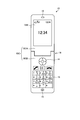
- FIG. 2 is a front view showing a schematic configuration of the portable communication device of the present invention shown in FIG.
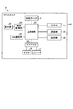
- FIG. 3 is a block diagram showing a schematic configuration of functions of the mobile communication device shown in FIG.
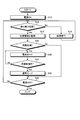
- FIG. 4 is a flowchart showing an example of the processing operation of the mobile communication device.
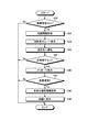
- FIG. 5 is a flowchart showing an example of processing operation of the mobile communication device.
- FIG. 6 is an explanatory diagram illustrating an example of an image displayed on the display unit of the mobile communication device.
- FIG. 7 is an explanatory diagram illustrating an example of an image displayed on the display unit of the mobile communication device.
- FIG. 1 is an explanatory diagram showing a schematic configuration of a communication system of the present invention having a portable communication device of the present invention.
- FIG. 2 is a front view showing a schematic configuration of the portable communication device of the present invention shown
- FIG. 8 is an explanatory diagram illustrating an example of an image displayed on the display unit of the mobile communication device.
- FIG. 9 is an explanatory diagram illustrating an example of an image displayed on the display unit of the mobile communication device.
- FIG. 10 is a flowchart showing an example of the processing operation of the mobile communication device.
- FIG. 11 is an explanatory diagram illustrating an example of an image displayed on the display unit of the mobile communication device.
- a mobile phone will be described as an example of the mobile communication device.
- the application target of the present invention is not limited to the mobile phone, and can be used for various communication devices having a call function.
- the present invention can be applied to PHS (Personal Handy-phone System), PDA, etc. as portable communication devices.
- the portable communication device can also be used for a dedicated crime prevention device having a communication function.
- a fixed terminal can also be used as a rescue side communication device (to be described later) constituting the communication system of the present invention.
- FIG. 1 is an explanatory diagram showing a schematic configuration of a communication system of the present invention having a portable communication device of the present invention.
- a communication system 1 shown in FIG. 1 includes a GPS satellite 2, a communication network 3, a server 6, a fixed terminal 7, a fixed telephone 9, and a plurality of mobile communication devices 10, 10a, 10b.
- the GPS satellite 2 is a satellite that transmits (provides) position information of the communication device to a communication device (communication terminal, communication device) having a communication function of GPS (Global Positioning System). Although only one GPS satellite 2 is shown in FIG. 1, the number of GPS satellites 2 (mainly three and four) necessary for specifying the position of the communication device is arranged.
- the plurality of GPS devices 2 output GPS signals (location information and time information of the GPS satellites 2) necessary for specifying the location information of the communication device.
- the communication device acquires its own position information by acquiring and analyzing the GPS signal output from the GPS satellite 2. The analysis may be performed by the communication device itself or may be performed by the external server 6.
- the communication network 3 is composed of a plurality of base stations, exchanges, and wired communication lines.
- the communication network 3 performs information communication between a communication device and another communication device using a wired or wireless communication line.
- the communication network 3 can use various communication methods as long as communication can be performed between communication devices. For example, communication may be performed using a satellite line.
- the server 6 has various data such as map information and information (telephone number, address) for identifying each communication device, and communicates with the communication device via the communication network 3 to supply various information.
- the server 6 also receives various types of information such as position information and GPS signals from the communication device and communicates information to other communication devices based on the information, and also relays information.
- the fixed terminal 7 is a fixed information terminal having an information communication function such as a PC (Personal Computer), and is connected to the communication network 3 by wire or wireless. Information is transmitted to and received from other communication devices via the communication network 3.
- the fixed telephone 8 is a telephone device connected to the communication network 3 via a wired telephone line.
- the mobile communication devices 10, 10 a, and 10 b are communication terminals that perform wireless communication with the communication network 3.
- the mobile communication device 10 transmits a signal such as an audio signal to the communication network 3 and receives a signal such as an audio signal from the communication network 3.
- Each mobile communication terminal is assigned and stored with a unique telephone number and terminal number. The configuration of the mobile communication devices 10, 10a, 10b will be described later.
- the communication system 1 is configured as described above.
- the mobile communication device 10 when a call operation is input to the mobile communication device 10 by a user's operation, the mobile communication device 10 sends a call signal and information of a communication destination telephone number to the communication network 3.
- the communication network 3 searches for the mobile communication device 10 to which the input communication destination telephone number is assigned, and notifies the communication destination mobile communication device 10 of an incoming call. Thereafter, the communication system 1 performs communication via the communication network 3 when a call start operation is input from the mobile communication device 10 that is the communication destination. That is, the communication system 1 performs communication between the mobile communication devices 10 by transmitting and receiving information via the communication network 3.
- the communication system 1 can communicate not only with the information communication between the mobile communication devices 10 but also with the mobile communication device 10 and the server 6, the mobile communication device 10 and the fixed terminal 7, and the mobile communication device 10 and the fixed phone 9. it can.
- communication between communication terminals is not limited to voice communication, and also transmits and receives data.
- the mobile communication device 10 constituting the communication system 1 can also acquire position information from the GPS satellite 2.
- FIG. 1 only one server 6, fixed terminal 7, and fixed telephone 9 are shown, and only three mobile communication devices 10 (10, 10a, 10b) are shown. 1 can be composed of a large number of servers 6, fixed terminals 7, fixed telephones 9, and portable communication devices 10.
- FIG. 2 is a front view showing a schematic configuration of the mobile communication device shown in FIG.
- the mobile communication device 10 is a mobile phone having a wireless communication function.
- the mobile communication device 10 is a foldable mobile phone in which a housing 10C is configured to be openable and closable by a first housing 10CA and a second housing 10CB.
- FIG. 2 shows a state where the mobile communication device 10 is opened.
- the casing 10C of the mobile communication terminal 10 is foldable, but the shape of the casing is not particularly limited.
- the casing can be in various forms, for example, a slide type, a sacroid type, a revolver type, a straight type, or the like.
- the first housing 10CA is provided with a main display 12M shown in FIG. 2 as a display unit.
- the main display 12M displays, as a predetermined image, a standby screen when the mobile communication device 10 is waiting for reception, or a menu image used to assist the operation of the mobile communication device 10.
- the first housing 10CA is provided with a receiver 16 that emits a voice when the mobile communication device 10 is talking.
- the second casing 10CB is provided with a plurality of operation keys 13 for inputting characters at the time of making a telephone number of the other party to call, mail creation, etc., and selection and determination of menus and screens displayed on the main display 12M
- a direction and determination key 14 is provided for easily executing scrolling and the like.
- the operation key 13 and the direction / decision key 14 constitute an operation unit 28 (see FIG. 3) of the mobile communication device 10.
- the second casing 10CB is provided with a microphone 15 that receives voice when the mobile communication device 10 is talking.
- first casing 10CA and the second casing 10CB are connected by a hinge 18. Accordingly, the first housing 10CA and the second housing 10CB are configured to rotate together around the hinge 18 so as to rotate in a direction away from each other and a direction approaching each other.
- the mobile communication device 10 opens, and when the first housing 10CA and the second housing 10CB rotate in a direction approaching each other, mobile communication The device 10 closes.
- FIG. 3 is a block diagram showing a schematic configuration of functions of the mobile communication device shown in FIG.
- the mobile communication device 10 includes a main control unit 22, a storage unit 24, a communication unit 26, an operation unit 28, an audio processing unit 30, a display unit 32, a display control unit 33, A GPS communication unit 34 and a security switch 36 are provided.
- the main control unit 22 is a processing unit that centrally controls the overall operation of the mobile communication device 10, for example, a CPU (Central Processing Unit). That is, the communication unit 26, the display unit, and the like so that various processes of the mobile communication device 10 are executed in an appropriate procedure according to the operation of the operation unit 28 and the software stored in the storage unit 24 of the mobile communication device 10. 32 and the like are controlled.
- the main control unit 22 executes processing based on programs (for example, operating system programs, application programs, etc.) stored in the storage unit 24. Further, the main control unit 22 can execute a plurality of programs (applications, software) in parallel.
- the storage unit 24 stores application programs and data used for processing in the main control unit 22. Specifically, as an application program, an application program that performs outgoing / incoming call processing, an application program that processes a crime prevention operation, an application program that processes a rescue operation, or an application program that transmits / receives mail Etc. are saved. As data, image data, audio data, dictionary data for character conversion, address book data, and the like are stored. In addition, a conversion table used in an application program for transmitting and receiving character information during a call is also provided.
- the communication unit 26 establishes a radio signal line by the CDMA method or the LTE method with the base station via the channel assigned by the base station of the communication network 3 described above, and performs telephone communication and information with the base station. Communicate. For this reason, the user can make a call with a desired partner through communication by the communication unit 26.
- the operation unit 28 includes, for example, an operation key 13 to which various functions such as a power key, a call key, a numeric key, a character key, and a call key are assigned, and a direction and determination key 14. When these keys are input by a user operation, the operation unit 28 generates a signal corresponding to the operation content. The generated signal is input to the main controller 22 as a user instruction.
- the audio processing unit 30 executes processing of an audio signal input to the microphone 15 and an audio signal output from the receiver 16.
- the display unit 32 includes a display panel (such as the main display 12M described above) configured by a liquid crystal display (LCD, Liquid Crystal Display), an organic EL (Organic Electro-Luminescence) panel, and the like.
- a display panel such as the main display 12M described above
- LCD Liquid Crystal Display
- organic EL Organic Electro-Luminescence
- the GPS communication unit 34 is a communication unit that receives a GPS signal transmitted from the GPS satellite 2. In addition, the GPS communication unit 34 calculates the latitude and longitude of the mobile communication device 10 from the received GSP signal, and sends information on the calculated latitude and longitude to the main control unit 22. The GPS communication unit 34 acquires GPS signals from a plurality of GPS satellites 2, and the distance from each GPS satellite 2 depending on the time difference between the time information included in the GPS signals and the acquired time information, the strength of the received radio waves, and the like. Is calculated. The GPS communication unit 34 calculates its own position by analyzing the distance from the GPS satellite 2 and the position information of each GPS satellite 2.
- the security switch 36 is a switch that can be switched ON and OFF by a user operation.
- the security switch 36 sends ON or OFF information to the main control unit 22.
- As the security switch 36 a switch whose position is changed by pulling or pushing can be used.
- As the crime prevention switch 36 a switch that is detachable from the housing 11 and that is connected to the housing 11 is turned on, and when it is detached from the housing 11, it is turned off. Can do.
- FIG. 4 is a flowchart showing an example of the processing operation of the mobile communication device.
- the mobile communication device 10 performs an operation in the crime prevention mode when a predetermined condition is satisfied by processing a program of an application for processing a crime prevention operation stored in the storage unit 24 by the main control unit 22. .
- the mobile communication device 10 is in a state in which the power is turned off, that is, the power supply to each unit is stopped and no image is displayed on the display unit 32. From this state, the mobile communication device 10 turns on the power as step S12. Specifically, the main control unit 22 turns on the power when the user presses the power button of the operation unit 28 or when the power-on operation is set by a timer or the like. When the instruction is detected, the power is turned on. That is, the main control unit 22 starts supplying power to each unit and activates various processing functions. Note that the main control unit 22 executes only a minimum function when the power is OFF.
- the main control unit 22 reads out an application program for processing the crime prevention operation from the storage unit 24 and activates an application for processing the crime prevention operation.
- the main control unit 22 turns on the power in step S12, the main control unit 22 starts the process of the crime prevention operation.
- the mobile communication device 10 determines whether it is in a standby state in step S14.
- the standby state is a state waiting for satisfying a user operation input or a preset condition (a state where a so-called standby screen is displayed). That is, the standby state is a state in which no applications other than programs that are always activated are not activated.
- step S14 determines in step S14 that it is not in a standby state (No)
- step S14 determines in step S14 that it is not in the standby state, it is in a state in which any application is being executed, and therefore the currently executing application (email transmission / reception, telephone call, website browsing) processing Execute.
- the main control unit 22 proceeds to step S14 and determines again whether it is in a standby state.
- the main control unit 22 determines in step S14 that it is in a standby state (Yes), it acquires position information as step S18. That is, the main control unit 22 communicates with the GPS satellite 2 by the GPS communication unit 34 and acquires its position information. Further, the main control unit 22 acquires map information including dangerous area information along with acquisition of its own position information.
- the acquisition method of map information is not specifically limited.
- the mobile communication device 10 may store the data in the storage unit 24 and read the data, or may acquire the data from an external storage device (server 6) or the like via the communication unit 26. At this time, the main control unit 22 may acquire the map information on the basis of the acquired own position information (for example, so as to include the own position information). Note that the main control unit 22 may detect an area in which the main control unit 22 is located by communication with the base station, and read or acquire map information in advance.
- the main control unit 22 determines whether it is a dangerous area in step S20. That is, the main control unit 22 determines whether or not its own position information acquired in step S18 is included in the dangerous area (dangerous area, dangerous area) (whether it is in the dangerous area).
- the danger area is the information of the area (area) acquired together with the map information. It is the area where the crime, the accident occurred, the security area, the dark area, the low traffic area, and the crime. It is an area that is more likely to be involved in dangerous matters such as other areas.
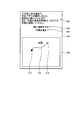
- a risk level is set according to the area. In the present embodiment, the degree of risk is set to four levels of “less than low”, “low”, “medium”, and “high”.
- step S20 determines in step S20 that it is not a dangerous area (No), that is, its own position information is not included in the dangerous area (outside the dangerous area), it proceeds to step S28. If the main control unit 22 determines in step S20 that it is a dangerous area (Yes), that is, its own position information is included in the dangerous area, the main control unit 22 sets a warning mode in step S22. The alert mode will be described later.
- the main control part 22 will determine whether it is out of a danger area as step S24, if warning mode is performed by step S22. More specifically, the main control unit 22 acquires its own position information in the same manner as in step S18 as step S24, and then collates its own position information with the information on the dangerous area. It is determined whether it is outside the danger zone, that is, whether it is outside the danger zone.
- Step S24 determines that it is not out of the dangerous area in Step S24 (No), that is, it is in the dangerous area, it proceeds to Step S22. That is, the main control unit 22 repeats the processes of step S22 and step S24 until it determines that it is outside the danger zone.
- step S24 determines in step S24 that it is out of the danger zone (Yes), that is, it is not in the danger zone, it sets the normal mode in step S26.
- the normal mode is a state that is not a warning mode. Thereafter, the main control unit 22 proceeds to step S28.
- the main control unit 22 determines whether or not to turn off the power as step S28 when it is determined No in step S20 and when the process of step S26 is completed. That is, the main control unit 22 determines whether there is an instruction to turn off the power and end the driving of the mobile communication device 10. Here, the main control unit 22 determines that an instruction to end is input when the power button of the operation unit 28 is pressed for a certain period of time or when the power-off operation is set by a timer or the like. If the main control unit 22 determines in step S28 that the power is not turned off (No), that is, it has not detected an instruction to turn off the power, the main control unit 22 proceeds to step S14 and repeats the above processing. If the main control unit 22 determines in step S28 that the power is off (Yes), that is, it has detected an instruction to turn off the power, the main control unit 22 performs a process of turning off the power and ends the process.
- the mobile communication device 10 determines whether the mobile communication device 10 is in the danger zone based on the position information of the mobile phone 10 and the map information including the danger zone information. Run the mode.
- FIG. 5 is a flowchart showing an example of processing operation of the mobile communication device.
- 6 to 9 are explanatory diagrams illustrating examples of images displayed on the display unit of the mobile communication device.
- the main control unit 22 lowers the threshold value of the battery (battery, power supply unit) so that it can be used for a longer time than usual.
- lowering the battery threshold means lowering at least one of the remaining battery level, voltage value, and current value of the battery being used, resulting in a lower battery level and lower voltage value.
- the mobile communication device 10 can be used even when the current value decreases. Thereby, the user can use the mobile communication device 10 for a longer time.
- the main control unit 22 notifies by voice that the vehicle has entered the dangerous area.
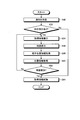
- the main control unit 22 determines whether the degree of risk is low or higher as step S30. That is, the main control unit 22 determines whether the danger level setting of the dangerous area including the acquired position information (position where the person is present) is low or higher, that is, low, medium, high (not less than low). ). If the main control unit 22 determines in step S30 that the degree of risk is not lower or higher (No), that is, the degree of risk is lower than low, the main control unit 22 ends the process. That is, the main control unit 22 ends the process only by notifying the fact that the battery threshold has been lowered and the danger zone has been entered as a warning mode.
- map information is acquired in step S32.
- the map information acquired in step S32 is map information including information such as roads and building arrangements.
- the map information may be obtained by reading the map information from an area where the map information is stored or temporarily stored.
- map information including the dangerous area information may be map information that can determine at least whether the position is the dangerous area, that is, information associated with the area (coordinates) of the dangerous area. There is no need for information such as road and building layout.
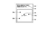
- the main control unit 22 After acquiring the map information in step S32, the main control unit 22 displays the map and route in step S34. That is, the main control unit 22 calculates a route to exit from the dangerous area based on its own position information, dangerous area information, and map information acquired in step S32. Thereafter, the main control unit 22 superimposes the calculated route and its position on the map information (synthesizes each information), creates an image, and causes the display unit 32 to display the created image.
- the main control unit 22 causes the display unit 32 to display an image 50 as shown in FIG.
- the image 50 includes a map 52.
- the map 52 displays road and building information for both the safe area 54 and the dangerous area 56.
- the safe area 54 is an area that is not a dangerous area.
- the boundary line between the safety area 54 and the danger area 56 is partitioned by a line.
- the main control unit 22 may display the safety area 54 and the dangerous area 56 in different colors. Further, the main control unit 22 may display the danger area 56 darker (or brighter) than the safety area 54 so that the danger area 56 becomes more conspicuous. That is, the main control unit 22 may display the safety area 54 and the dangerous area 56 with different brightness.
- the main controller 22 also displays its own position information (user's current position) 58 as a dot. Further, the main control unit 22 displays a route 60 from the current position to the safety area 54 with a line.
- the route 60 can be various routes depending on the setting, but it is preferable to display the shortest route or the route that can be determined to be the safest. By displaying the shortest route, the user can be moved to the safe area 54 in a short time. Further, by displaying the route that can be determined to be the safest, the risk of being involved in a crime, an accident, or the like can be reduced.
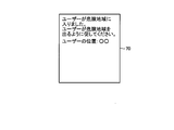
- the main control unit 22 After displaying the map and the route in step S34, the main control unit 22 performs notification (that is, sending an emergency signal) to the designated destination in step S36.
- the designated destination is a communication device of a preset person, facility, or organization such as a guardian, a parent, a police station, or a school.
- the main control unit 22 notifies the designated destination by voice or message that the mobile communication terminal 10 is in the dangerous area (the user is in the dangerous area).
- the main control part 22 should just send the image 70 as shown in FIG.
- the image 70 shown in FIG. 7 is composed of a message “The user has entered the dangerous area. Please urge the user to leave the dangerous area.” And the user's position information “User position: XX”.
- the message, the display method of the user's location information, and the text are not limited to this, and any configuration may be used as long as the user has entered the danger zone and can notify the user's location.
- the main control unit 22 sends the image 70 to the designated communication device via the communication unit 26.
- the terminal (server 6) of the security system can also be designated.
- step S34 and step S36 may be performed in the reverse order, and may be performed simultaneously.
- the main control unit 22 determines whether the degree of risk is medium or higher as step S38. That is, it is determined whether the danger level setting of the dangerous area including the acquired position information (position where the person is present) is medium or higher, that is, medium or high. If the main control unit 22 determines in step S38 that the degree of risk is not medium or higher (No), that is, the degree of risk is low, the main control unit 22 ends the process.
- step S40 a message is displayed in step S40. That is, the main control part 22 displays a message on the display part 32 in addition to map information as step S40. Specifically, the main control unit 22 causes the display unit 32 to display an image 80 shown in FIG.
- the image 80 has a map 82 and a message 84 composed of character information.
- the map 82 is basically the same map as the map 52 displayed in the image 50 of FIG. 6 described above.
- the message 84 is a sentence "This is a dangerous area. Please exit the dangerous area according to the map guide.”
- the message 84 is not limited to the text of the present embodiment, and may be a text requesting movement from the dangerous area to the safe area.
- the main control unit 22 displays an image 80 every 5 minutes.
- the main control part 22 will determine whether a risk is high as step S42, after complete
- the main control unit 22 determines that the degree of risk is high (Yes) in step S42, the main control unit 22 acquires information on one or more safe places as step S44.
- the safe place is a safe place, that is, a place that can serve as an evacuation place even in the dangerous area.
- police boxes, convenience stores, shops, buildings where security guards are stationed The main control unit 22 can acquire a safe place by various methods. Specifically, the main control unit 22 can acquire by a method similar to the map information described above.
- the main control part 22 will display on a map as step S46, if the information of a safe place is acquired at step S44. Specifically, the main control unit 22 causes the display unit 32 to display an image 90 shown in FIG. In addition, when there are a plurality of safe places, the main control unit 22 selects a place having the shortest distance to the place, or gives priority to a place that can pass through a relatively low risk area. It is preferable to select them. Further, a route to a safe place may be displayed.
- the image 90 has a map 92 and a message 94 composed of character information.
- the position 96 of the user and the safe places 98a, 98b, 98c are displayed.
- the safe places 98a, 98b, and 98c are each indicated by a red dot.
- the message 94 is a sentence “The safe place is a red dot on the following map.” That is, the message 94 is an explanatory text of a method for identifying a safe place.
- the main control unit 22 displays an image 90 every 5 minutes.
- the main control unit 22 ends the security mode process.
- the main control unit 22 repeats the process of the crime prevention mode shown in FIG. 5 until shifting to the normal mode.
- the mobile communication device 10 when the mobile communication device 10 detects that the mobile communication device 10 has entered the dangerous area, the mobile communication device 10 can reduce the risk of being involved in a crime, an accident, or the like by executing the alert mode. Further, by changing the process to be executed according to the danger level of the dangerous area, it is possible to execute a warning according to the danger level.
- the mobile communication device 10 can efficiently escape from the dangerous area by displaying the map information and the route 60 for escaping from the dangerous area on the display unit 32, and is involved in a crime, an accident, or the like. Fear can be further reduced.
- the mobile communication device 10 can move to a safe place without any hesitation when the danger is approaching by displaying information on the safe place in the dangerous area on the map. Thereby, the risk of getting involved in crimes, accidents, etc. can be further reduced.
- the processing to be executed is changed in accordance with the degree of risk in order to efficiently and sufficiently execute warning, but the present invention is not limited to this. Further, the processing performed according to each risk level may be performed according to any risk level.
- the mobile communication device 10 has a shooting function or a recording function
- the warning mode is executed or when a predetermined risk level is achieved
- images are taken every predetermined time or moving images are shot. May be started, or recording may be started.
- the mobile communication device 10 is not limited to the route to the safe area, and may display the route to the safe place. Thereby, it can move to a safe place safely in a short time.
- FIG. 10 is a flowchart illustrating an example of the processing operation of the mobile communication device
- FIG. 11 is an explanatory diagram illustrating an example of an image displayed on the display unit of the mobile communication device.
- the main control unit 22 of the mobile communication device 10b receives a notification in step S50. That is, the control unit 22 receives information that has entered the danger area from the mobile communication device 10 a via the communication unit 26.
- the processing of each unit of the mobile communication device 10 b is basically performed unless otherwise specified.
- the main control part 22 will determine whether there exists a corresponding instruction
- step S52 determines in step S52 that there is no response instruction (No), that is, an instruction not to perform a rescue operation has been input, or no operation has been input for a certain period of time, the process proceeds to step S64.
- step S52 determines in step S52 that there is a response instruction (Yes), that is, if an instruction to perform a rescue operation is input, the main control unit 22 displays the acquired information in step S54 and displays the map in step S56. . Note that the main control unit 22 causes the display unit 32 to display the acquired information and map as one image 100, as shown in FIG.
- the image 100 includes a message 102, a map 104, an item 106, and an item 108.
- the message 102 is the sentence "The crime prevention buzzer has operated at the red dot below. Please rescue.
- the subject's physical characteristics are XX. Please refer to the photograph.”
- the map 104 displays the position 110 of the mobile communication device 10a, the own position 112, and the route 114 from the own position 112 to the position 110 of the mobile communication device 10a.
- the main control unit 22 uses the GPS communication unit 36 to detect its own position information, and acquires the position information and map information of the mobile communication device 10a. Then, based on the acquired position information of the mobile communication device 10a and the map information, a travel route from the mobile device 10a to the mobile communication device 10a is calculated. In this way, the acquired or calculated positions 110 and 112 and the route 114 are displayed on the map 104 in an overlapping manner.
- the map information and the location information of the mobile communication device 10a may be acquired together with the notification received in step S50, or may be acquired through separate communication. Further, the map information may use data stored in its own storage unit 24 as described above.
- the item 106 is an item associated with a sentence “contact a parent”, and the item 108 is an item associated with a sentence “view a photo”.
- each of the items 106 and 108 has a shortcut function.
- the main control unit 22 makes a call without displaying the telephone number on the communication device registered as the parent communication device. Further, when the item 108 is selected (clicked), the main control unit 22 displays a photograph.
- the main control part 22 will acquire partner position information as step S58, if a map is displayed by step S56. That is, the position information of the mobile communication device 10a is acquired (updated) again.
- the main control unit 22 acquires the position information of the other party in step S58, the main control unit 22 also acquires (updates) its own position information in step S60.
- the main control unit 22 determines whether or not the situation has been solved in step S62. That is, the main control unit 22 determines whether the user of the mobile communication device 10a has been rescued.
- the main control unit 22 can be set to determine whether the user has been rescued based on various criteria. For example, if the position information detected in step S58 is outside the danger zone, it can be set to determine that the rescue has been performed. Further, if the position information detected in step S58 and the position information detected in step S60 have the same coordinates, it can be set to determine that the other party has been found and rescued. Moreover, it can also be set as the determination which rescued if the operator of the portable communication apparatus 10a or the portable communication apparatus 10b input predetermined
- step S62 determines in step S62 that the situation has not been resolved (No)
- the main control unit 22 proceeds to step S54 and repeats the above processing. Further, when determining that the situation has been solved (Yes) in Step S62, the main control unit 22 deletes the acquired information as Step S64, that is, deletes the information acquired in Step S50, and ends the process.
- the mobile communication device 10 (in the present embodiment, the mobile communication device 10b) can perform the above-described processing by executing the application for processing the rescue operation. That is, by displaying the route to the mobile communication device 10a based on the location information of itself, the location information of the mobile communication device 10a that sent the notification, and the map information, the mobile communication device 10a You can reach the place where the owner is. Moreover, since the main control unit 22 repeats the processing from step S54 to step S62 until the situation is resolved, each position information can be updated, and even in a state of moving relative to each other, in a shorter time. It is possible to reach the place where the owner of the portable communication device 10a is. In addition, by displaying the position as an image, it is possible to notify a person who does not notice the sound. That is, even if the screaming is not heard, it is possible to reach the place where the owner of the mobile communication device 10a is present.
- the mobile communication device 10a is accurately detected. Can find the owner of Furthermore, when the situation is solved, the leakage of personal information can be suppressed by deleting the information. Further, as in the present embodiment, personal information can be prevented from leaking by not displaying the telephone number directly, displaying it as text information, and not displaying it when making a call.
- the personal information not to be displayed is not limited to a telephone number, but can be applied to an e-mail address or the like. Moreover, it is preferable to set such information to be untransferable. Thereby, it can suppress that personal information leaks.
- the position information of the rescue target can be accurately known based on the GPS signal, a person who is closer to the rescue target can quickly go to rescue. In addition, since it is possible to prevent the person from going to the rescue in reality, the rescue can be performed efficiently.
- the rescue communication device is a portable communication device.
- the present invention is not limited to this, and a fixed communication device, specifically, a fixed terminal and a fixed telephone can also be used. In the case of a fixed telephone, it is preferable to display an image using the FAX function.
- the map information may be stored in the rescue communication device so that only the position information is notified.
- the communication system 1 uses one of the servers 6 as a service server 6 that provides these security systems.
- the user of the mobile communication device 10a designates the server 6 as the designation destination.
- the server 6 establishes a communication device (contact station fixed phone, fixed terminal, police officer, mobile communication device owned by a patrol guard, convenience store fixed) for each area set as a dangerous area. (Telephone, fixed terminal) information.
- the mobile communication device 10a when the mobile communication device 10a receives the information indicating that the mobile communication device 10a is in the dangerous area, the mobile communication device 10a transmits a notification to the communication device that is in the dangerous area and serves as a contact. In this way, the server 6 can temporarily receive the information from the portable communication device 10a and transmit the information all at once to the communication devices around the point, so that the person to be rescued can be rescued in a shorter time. .
- the server 6 periodically receives position information from the mobile communication device 10 set as the rescue communication device, and receives a notification from the mobile communication device 10a. You may make it notify the rescue request also with respect to the mobile communication apparatus in a fixed range. Note that the communication system 1 can notify the rescue request to all of the mobile communication devices 10 in a predetermined area, but is set in advance in order to more securely protect personal information. You may make it send the notification of a rescue request to the portable communication apparatus 10 in a fixed area
- the server 6 can accurately specify the position of the portable communication device that has made a rescue request, and can select the rescue-side communication device from that position. As a result, the number and range of communication devices to which the server 6 performs notification can be narrowed down, and highly effective notification can be performed. Further, by narrowing down the number of communication devices, it is possible to further reduce the risk of leakage of personal information.
- the server 6 transmits, as the first notification, the position information of the mobile communication device 10a and a notification for confirming whether it can be supported (whether it will be rescued), and then transmits a compatible notification.
- the personal information may be transmitted only to the communication device. Thereby, it can suppress transmitting personal information to the communication apparatus more than necessary.
- information is transmitted from the mobile communication device 10 (or 10a) when entering any dangerous area, but the present invention is not limited to this.
- a notification requesting rescue (notification of occurrence of an emergency situation) may be made to a designated destination.
- the load of processing and monitoring as the communication system 1 increases, the same operation may be performed when the crime prevention switch 36 is turned on even outside the dangerous area.
- the determination of the risk level may be switched between the ON state and the OFF state of the crime prevention switch 36. That is, even when the crime prevention switch 36 is in the OFF position, it may be determined that the risk level is low, and when the security switch 36 is in the ON state, it may be determined that the risk level is high.
- dangerous areas can be added, changed, or deleted according to user settings.
- an appropriate dangerous area can be set according to a person who owns the mobile communication device, for example, a child or an elderly person.
- the risk level determination based on the owner may be performed on the risk zone. For example, if the owner of the mobile communication device is prohibited from drinking alcohol, the bar town may be set as a dangerous area. Accordingly, even when the user takes an inappropriate action, it is possible to be notified that it is dangerous.
- the main control unit 22 determines whether or not the user is in the dangerous area by using voice information in addition to the position information. For example, by receiving voice, it can be determined whether you are in a pachinko parlor. When using audio information, it may be determined based on whether a sound unique to the place has been received or the volume of the audio. Thus, a position can be specified with higher accuracy by combining position information and other information.
- the information on the dangerous area may be appropriately acquired from an external storage device such as the server 6 or the like, but is updated every certain period (from one month to two months) and, as described above, the user However, it is preferable to adjust in consideration of the season and time. Thereby, a dangerous area can be set more appropriately. In addition, communication costs and battery consumption can be reduced. It is preferable that the dangerous area is set not by a portable communication device to be protected but by a communication device set as a guardian. Thereby, it can suppress that a setting is changed arbitrarily.
- the mobile terminal device may include both an application program for processing a crime prevention operation and an application program for processing a rescue operation, but includes only one of them. Also good. That is, the mobile terminal device may have both a function of transmitting an emergency signal (requesting rescue) and a function of receiving an emergency signal (rescuing), but the side requesting rescue. It is good also as a structure provided only with the function of only the function of the side which performs only the function of the side which rescues. If both functions are provided, the function to be used (executed) may be selected depending on the situation.
- the communication system and the portable communication device according to the present invention are useful for use as a communication device having a crime prevention function.
Landscapes
- Engineering & Computer Science (AREA)
- Computer Networks & Wireless Communication (AREA)
- Signal Processing (AREA)
- Business, Economics & Management (AREA)
- Emergency Management (AREA)
- Human Computer Interaction (AREA)
- Telephone Function (AREA)
- Telephonic Communication Services (AREA)
- Alarm Systems (AREA)
Priority Applications (1)
| Application Number | Priority Date | Filing Date | Title |
|---|---|---|---|
| US13/575,172 US9497045B2 (en) | 2010-01-27 | 2011-01-27 | Communication system and mobile communication device for providing position information, map information and evacuation route in case of emergency |
Applications Claiming Priority (2)
| Application Number | Priority Date | Filing Date | Title |
|---|---|---|---|
| JP2010-016047 | 2010-01-27 | ||
| JP2010016047A JP5603606B2 (ja) | 2010-01-27 | 2010-01-27 | 通信システム及び携帯通信装置 |
Publications (1)
| Publication Number | Publication Date |
|---|---|
| WO2011093398A1 true WO2011093398A1 (ja) | 2011-08-04 |
Family
ID=44319381
Family Applications (1)
| Application Number | Title | Priority Date | Filing Date |
|---|---|---|---|
| PCT/JP2011/051645 Ceased WO2011093398A1 (ja) | 2010-01-27 | 2011-01-27 | 通信システム及び携帯通信装置 |
Country Status (3)
| Country | Link |
|---|---|
| US (1) | US9497045B2 (enExample) |
| JP (1) | JP5603606B2 (enExample) |
| WO (1) | WO2011093398A1 (enExample) |
Cited By (1)
| Publication number | Priority date | Publication date | Assignee | Title |
|---|---|---|---|---|
| CN111383424A (zh) * | 2020-04-15 | 2020-07-07 | 广东小天才科技有限公司 | 一种紧急求救方法及电子设备、计算机可读存储介质 |
Families Citing this family (10)
| Publication number | Priority date | Publication date | Assignee | Title |
|---|---|---|---|---|
| CN103765860B (zh) | 2011-12-20 | 2017-06-09 | 株式会社尼康 | 电子设备 |
| US9319450B2 (en) * | 2012-12-10 | 2016-04-19 | At&T Intellectual Property I, L.P. | Emergency alert messages via social media |
| CN105761439B (zh) * | 2014-12-17 | 2019-09-13 | 富泰华工业(深圳)有限公司 | 侦测空气污染的移动终端、系统及方法 |
| JP6464483B2 (ja) * | 2015-06-09 | 2019-02-06 | 清水建設株式会社 | 緊急通報システム、緊急通報装置、緊急通報方法、プログラム |
| US10616396B2 (en) * | 2016-06-28 | 2020-04-07 | Adam Gersten | Danger detection system |
| ES2931462T3 (es) * | 2016-09-27 | 2022-12-29 | Huawei Tech Co Ltd | Método y terminal para la visualización de la ubicación geográfica actual en una interfaz de llamadas de emergencia |
| US10893400B2 (en) | 2017-03-10 | 2021-01-12 | Blackberry Limited | Pedestrian safety communication system and method |
| JP2020177300A (ja) * | 2019-04-15 | 2020-10-29 | 株式会社L is B | 危険予知システム、危険予知装置、危険予知方法および危険予知プログラム |
| WO2022168933A1 (ja) * | 2021-02-05 | 2022-08-11 | 株式会社grigry | 緊急事態検出装置、緊急事態検出システム及び緊急事態検出方法 |
| US11764898B2 (en) * | 2021-08-05 | 2023-09-19 | Qualcomm Incorporated | Dynamically enabled vehicle-to-everything (V2X) pedestrian mode for mobile devices |
Citations (10)
| Publication number | Priority date | Publication date | Assignee | Title |
|---|---|---|---|---|
| JPH0965416A (ja) * | 1995-08-22 | 1997-03-07 | Hitachi Zosen Corp | 位置認識方法および位置認識装置 |
| JP2004221810A (ja) * | 2003-01-14 | 2004-08-05 | Hitachi Kokusai Electric Inc | 通信システム |
| JP2004318393A (ja) * | 2003-04-15 | 2004-11-11 | Nissan Motor Co Ltd | メッセージ交換システム |
| JP2006250792A (ja) * | 2005-03-11 | 2006-09-21 | Takenaka Komuten Co Ltd | 経路情報管理システム |
| JP2006524316A (ja) * | 2003-04-23 | 2006-10-26 | ノーベル,エルエルシー | 位置特定システム及び位置特定方法 |
| JP2009065340A (ja) * | 2007-09-05 | 2009-03-26 | Ntt Comware Corp | 連絡システム、情報管理サーバ装置、連絡方法 |
| JP2009193315A (ja) * | 2008-02-14 | 2009-08-27 | Mitsubishi Space Software Kk | 危険報知サーバ、携帯端末、危険報知方法、要因情報検知方法、プログラム |
| JP2009198239A (ja) * | 2008-02-20 | 2009-09-03 | Fujitsu Ltd | 経路探索支援装置、経路探索支援方法および経路探索支援プログラム |
| JP2009296529A (ja) * | 2008-06-09 | 2009-12-17 | Nec Saitama Ltd | 携帯端末装置、その制御方法及びプログラム |
| JP2010004177A (ja) * | 2008-06-18 | 2010-01-07 | Nec Access Technica Ltd | 災害情報提供システム |
Family Cites Families (8)
| Publication number | Priority date | Publication date | Assignee | Title |
|---|---|---|---|---|
| JPH0265416A (ja) | 1988-08-31 | 1990-03-06 | Fujitsu Ltd | 局監視システムの予備回線接続装置 |
| US6980813B2 (en) | 2000-07-14 | 2005-12-27 | Norbelle, Llc | Locating system and method |
| US7308274B2 (en) * | 2000-07-14 | 2007-12-11 | Norbelle, Llc | Locating system and method |
| JP2003060752A (ja) | 2001-08-09 | 2003-02-28 | Terufumi Tsukuda | 警報ブザー付き携帯電話機 |
| JP2003284120A (ja) * | 2002-03-20 | 2003-10-03 | Fuji Photo Film Co Ltd | 携帯通信端末用警告装置 |
| US20050190053A1 (en) * | 2003-01-24 | 2005-09-01 | Diegane Dione | Managing an occupant of a structure during an emergency event |
| JP2006053838A (ja) | 2004-08-16 | 2006-02-23 | Sofmac Systems Co Ltd | 犯罪情報通知装置 |
| JP5110829B2 (ja) | 2006-08-31 | 2012-12-26 | 三菱スペース・ソフトウエア株式会社 | 安全情報提供装置、安全情報提供システム、安全情報提供プログラム、安全情報提供方法、端末及び端末プログラム |
-
2010
- 2010-01-27 JP JP2010016047A patent/JP5603606B2/ja active Active
-
2011
- 2011-01-27 US US13/575,172 patent/US9497045B2/en active Active
- 2011-01-27 WO PCT/JP2011/051645 patent/WO2011093398A1/ja not_active Ceased
Patent Citations (10)
| Publication number | Priority date | Publication date | Assignee | Title |
|---|---|---|---|---|
| JPH0965416A (ja) * | 1995-08-22 | 1997-03-07 | Hitachi Zosen Corp | 位置認識方法および位置認識装置 |
| JP2004221810A (ja) * | 2003-01-14 | 2004-08-05 | Hitachi Kokusai Electric Inc | 通信システム |
| JP2004318393A (ja) * | 2003-04-15 | 2004-11-11 | Nissan Motor Co Ltd | メッセージ交換システム |
| JP2006524316A (ja) * | 2003-04-23 | 2006-10-26 | ノーベル,エルエルシー | 位置特定システム及び位置特定方法 |
| JP2006250792A (ja) * | 2005-03-11 | 2006-09-21 | Takenaka Komuten Co Ltd | 経路情報管理システム |
| JP2009065340A (ja) * | 2007-09-05 | 2009-03-26 | Ntt Comware Corp | 連絡システム、情報管理サーバ装置、連絡方法 |
| JP2009193315A (ja) * | 2008-02-14 | 2009-08-27 | Mitsubishi Space Software Kk | 危険報知サーバ、携帯端末、危険報知方法、要因情報検知方法、プログラム |
| JP2009198239A (ja) * | 2008-02-20 | 2009-09-03 | Fujitsu Ltd | 経路探索支援装置、経路探索支援方法および経路探索支援プログラム |
| JP2009296529A (ja) * | 2008-06-09 | 2009-12-17 | Nec Saitama Ltd | 携帯端末装置、その制御方法及びプログラム |
| JP2010004177A (ja) * | 2008-06-18 | 2010-01-07 | Nec Access Technica Ltd | 災害情報提供システム |
Cited By (1)
| Publication number | Priority date | Publication date | Assignee | Title |
|---|---|---|---|---|
| CN111383424A (zh) * | 2020-04-15 | 2020-07-07 | 广东小天才科技有限公司 | 一种紧急求救方法及电子设备、计算机可读存储介质 |
Also Published As
| Publication number | Publication date |
|---|---|
| JP2011155522A (ja) | 2011-08-11 |
| US20120295579A1 (en) | 2012-11-22 |
| JP5603606B2 (ja) | 2014-10-08 |
| US9497045B2 (en) | 2016-11-15 |
Similar Documents
| Publication | Publication Date | Title |
|---|---|---|
| JP5603606B2 (ja) | 通信システム及び携帯通信装置 | |
| US10051119B2 (en) | Caller location determination systems and methods | |
| US7174150B2 (en) | Method for processing information associated with disaster | |
| US9911315B2 (en) | Personalized real time outdoor guidance application for mass evacuation | |
| US20110136463A1 (en) | System and method for controlling an emergency event in a region of interest | |
| CN110636444A (zh) | 地震预警方法、装置及存储介质 | |
| KR20120127641A (ko) | 이머전시 리스폰스 명령의 통신을 위한 방법 및 장치 | |
| JP5217654B2 (ja) | 携帯端末装置、その制御方法及びプログラム | |
| JP2007087139A (ja) | 災害時安否情報収集・管理システム,方法,携帯端末およびプログラム | |
| JP2004355243A (ja) | 移動体通信端末装置及び監視システム | |
| JP2013021435A (ja) | 無線通信端末装置及び無線通信方法 | |
| JP5757913B2 (ja) | 携帯通信装置、通信システム、制御方法及び制御プログラム | |
| JP4173268B2 (ja) | 移動体位置確認システムおよび方法 | |
| JP2006072416A (ja) | 情報処理装置 | |
| WO2013136976A1 (ja) | 端末装置、及び安否確認システム | |
| JP2008234562A (ja) | セキュリティシステム、携帯端末装置及びセキュリティ方法 | |
| JP4081685B2 (ja) | 監視装置および方法、並びに記録媒体 | |
| JP5122413B2 (ja) | 安否確認システムおよび監視センタ装置 | |
| JP2021180048A (ja) | 安否確認情報提供装置、携帯端末、安否確認情報提供方法およびプログラム | |
| JP2013176000A (ja) | 携帯端末及びその制御方法 | |
| KR20110090289A (ko) | 위치 안내 장치 및 방법 | |
| KR101547947B1 (ko) | 모바일폰을 이용한 위급상황 알림 시스템 및 그 방법. | |
| JP2010102635A (ja) | 情報処理システム、携帯端末、サーバ、プログラム及び携帯端末の位置通知方法 | |
| KR20160133024A (ko) | 위급상황 알림단말장치, 방법 및 컴퓨터로 판독 가능한 기록 매체 | |
| JP5891104B2 (ja) | 通信システム、携帯通信装置、及び制御プログラム |
Legal Events
| Date | Code | Title | Description |
|---|---|---|---|
| 121 | Ep: the epo has been informed by wipo that ep was designated in this application |
Ref document number: 11737109 Country of ref document: EP Kind code of ref document: A1 |
|
| WWE | Wipo information: entry into national phase |
Ref document number: 13575172 Country of ref document: US |
|
| NENP | Non-entry into the national phase |
Ref country code: DE |
|
| 122 | Ep: pct application non-entry in european phase |
Ref document number: 11737109 Country of ref document: EP Kind code of ref document: A1 |