WO2011092964A1 - 掘削機のビット交換装置 - Google Patents
掘削機のビット交換装置 Download PDFInfo
- Publication number
- WO2011092964A1 WO2011092964A1 PCT/JP2010/072604 JP2010072604W WO2011092964A1 WO 2011092964 A1 WO2011092964 A1 WO 2011092964A1 JP 2010072604 W JP2010072604 W JP 2010072604W WO 2011092964 A1 WO2011092964 A1 WO 2011092964A1
- Authority
- WO
- WIPO (PCT)
- Prior art keywords
- bit
- valve
- passage
- case
- reaction force
- Prior art date
- Legal status (The legal status is an assumption and is not a legal conclusion. Google has not performed a legal analysis and makes no representation as to the accuracy of the status listed.)
- Ceased
Links
Images









Classifications
-
- E—FIXED CONSTRUCTIONS
- E21—EARTH OR ROCK DRILLING; MINING
- E21D—SHAFTS; TUNNELS; GALLERIES; LARGE UNDERGROUND CHAMBERS
- E21D9/00—Tunnels or galleries, with or without linings; Methods or apparatus for making thereof; Layout of tunnels or galleries
- E21D9/04—Driving tunnels or galleries through loose materials; Apparatus therefor not otherwise provided for
-
- E—FIXED CONSTRUCTIONS
- E21—EARTH OR ROCK DRILLING; MINING
- E21D—SHAFTS; TUNNELS; GALLERIES; LARGE UNDERGROUND CHAMBERS
- E21D9/00—Tunnels or galleries, with or without linings; Methods or apparatus for making thereof; Layout of tunnels or galleries
- E21D9/06—Making by using a driving shield, i.e. advanced by pushing means bearing against the already placed lining
- E21D9/08—Making by using a driving shield, i.e. advanced by pushing means bearing against the already placed lining with additional boring or cutting means other than the conventional cutting edge of the shield
- E21D9/0875—Making by using a driving shield, i.e. advanced by pushing means bearing against the already placed lining with additional boring or cutting means other than the conventional cutting edge of the shield with a movable support arm carrying cutting tools for attacking the front face, e.g. a bucket
- E21D9/0879—Making by using a driving shield, i.e. advanced by pushing means bearing against the already placed lining with additional boring or cutting means other than the conventional cutting edge of the shield with a movable support arm carrying cutting tools for attacking the front face, e.g. a bucket the shield being provided with devices for lining the tunnel, e.g. shuttering
-
- E—FIXED CONSTRUCTIONS
- E21—EARTH OR ROCK DRILLING; MINING
- E21D—SHAFTS; TUNNELS; GALLERIES; LARGE UNDERGROUND CHAMBERS
- E21D9/00—Tunnels or galleries, with or without linings; Methods or apparatus for making thereof; Layout of tunnels or galleries
- E21D9/10—Making by using boring or cutting machines
- E21D9/11—Making by using boring or cutting machines with a rotary drilling-head cutting simultaneously the whole cross-section, i.e. full-face machines
- E21D9/112—Making by using boring or cutting machines with a rotary drilling-head cutting simultaneously the whole cross-section, i.e. full-face machines by means of one single rotary head or of concentric rotary heads
Definitions
- the present invention allows exchanging roller bits (disc cutters) worn by crushing rocks and gravel during excavation work in excavator cutter heads such as shield machines from the working space provided in the cutter head.
- the present invention relates to an excavating bit replacement device.
- Patent Document 1 and Patent Document 2 have been proposed as techniques of a bit exchanging apparatus that replaces a worn roller bit with a new roller bit from a work space formed in a cutter head during excavation work.
- a rotating body having an opening is disposed on the front surface of the cutter pork, and a roller bit is disposed in the opening of the rotating body.
- the rotating body is rotated 90 ° or 180 ° so that the opening of the rotating body faces the replacement opening provided on the side surface or the back surface thereof, and the roller bit is They are exchanged by being extracted from the opening of the rotating body into the work space via the replacement opening.
- a rotating body is disposed on the front surface of the cutter head (cutting pork), and a sliding gap between the rotating body and its support member is exposed facing the front surface of the cutter head. For this reason, during excavation, there is a risk that mud pressure may be directly applied to the sliding gap, and fragments such as gravel may enter the gap. There was a risk that the movement was disturbed.
- the present invention solves the above-mentioned problems, improves the sealing performance in the sliding gap of the rotating body in which the roller bit is arranged, and replaces the roller bit by smoothly rotating the rotating body during replacement during excavation.
- An object of the present invention is to provide a bit exchanging device for an excavator.
- a first aspect of the present invention provides a cutter head rotatably supported around an axis of an excavator at a front portion of an excavator body, and disposed on a front surface of the cutter head.
- a excavator bit exchanging device comprising a roller bit for crushing and a working space formed in the cutter head and capable of exchanging the worn roller bit, Install the housing at the front of the cutter head, In the housing, a bit accommodating passage is formed along an exit / retreat axis for exiting and retracting the roller bit, In the bit accommodating passage, a bit accommodating portion that opens to the front surface of the cutter head and a valve accommodating portion formed at the rear portion are provided, In the housing, in the insertion / removal axis direction separated by a predetermined angle with respect to the retracting / retracting axis, an exchange opening that communicates the valve housing and the working space is formed.
- a rotation valve that is rotatable around a rotation axis that is substantially orthogonal to the extension / retraction axis and the insertion / removal axis is provided.
- An attachment / detachment passage communicating with the bit accommodating portion is formed in the rotating valve, In the attachment / detachment passage, the bit case having the roller bit is detachably disposed, A bit case can be inserted and removed between the attachment / detachment passage and the work space by rotating the turning valve by a predetermined angle to connect the attachment / detachment passage to the replacement opening.
- the rotating valve is provided with a bit retracting mechanism for moving the bit case between the attaching / detaching passage and the bit accommodating portion, Providing a first sealing material for stopping the gap between the bit case and the valve housing;
- a second seal member is provided on the outer peripheral surface of the rotating valve to stop the gap between the periphery of the opening of the attachment / detachment passage and the inner surface of the valve housing portion.
- the invention according to claim 2 is the configuration according to claim 1, A reaction force support block for transmitting and supporting the excavation reaction force of the roller bit to the housing is provided on the back side of the bit case in the attachment / detachment passage of the rotation valve, A cotter member for transmitting a digging reaction force is provided between the bit case and the reaction force support block in the valve housing portion so as to be freely detachable.
- the invention according to claim 3 is the configuration according to claim 1 or 2, Forming the bit receiving passage through the cutter head; Forming the detachable passage through the rotating valve;
- the reaction force support block is detachably disposed in the attachment / detachment passage, The reaction force support block can be inserted into and removed from the work space from the rear opening of the attachment / detachment passage of the rotating valve through the replacement opening.
- a case earthing passage for accommodating the roller bit is formed penetrating in the exit / retreat axis direction
- a block discharge passage communicating with the case discharge passage is formed penetrating in the exit / retreat axis direction
- a valve accommodating portion that accommodates a rotating valve is formed behind the bit accommodating portion that is opened on the front surface of the cutter head, and the bit case having a roller bit is disposed in the rotating manner. Since it is used by projecting and moving from the valve attachment / detachment passage to the bit housing portion, the sliding gap between the rotating valve and the valve housing portion may be covered with the bit case and exposed to the front surface of the cutter head. In addition, the gap between the bit accommodating portion and the bit case is stopped by the first sealing material, and the muddy water pressure during excavation is supported by the first sealing material.
- the excavation reaction force transmitted from the bit case via the cotter member can be supported by the housing via the reaction force support block on the back side of the attachment / detachment passage.
- the reaction force can be effectively supported.
- the roller bit can be easily replaced by first extracting the reaction force support block from the attachment / detachment passage and then extracting the bit case from the attachment / detachment passage. Moreover, the choice of the rotation direction of a rotation valve can be expanded.
- the excavated material excavated by the roller bit can be smoothly discharged from the case discharging passage to the back side of the cutter head through the block discharging passage, It can be crushed well.
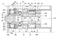
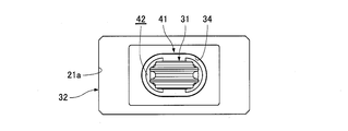
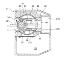
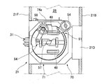
- FIG. 2 is a cross-sectional view taken along the line AA shown in FIG. It is a principal part enlarged view of FIG. It is a partially cutaway perspective view of the main cutter pork showing a bit exchange unit. It is a front view which shows a bit exchange unit.
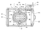
- FIG. 2 is a cross-sectional view taken along line BB shown in FIG.
- FIG. 5 is an exploded longitudinal sectional view in which a bit case and a reaction force receiving block are detached from a rotating valve. It is a disassembled perspective view which shows a bit case and a reaction force receiving block.
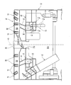
- FIG. 1 It is a perspective view which shows a sealing material. It is a front view which shows the cutter head of the shield machine which has a bit exchange unit. It is a center longitudinal cross-sectional view of the shield machine which has a bit exchange unit. It is a center cross-sectional view of the bit exchange unit showing the retracted position of the bit case in the roller bit exchange operation. It is the center longitudinal cross-sectional view of the bit exchange unit which shows the retreat position of a bit case in the exchange operation
- FIG. 5 is a central cross-sectional view of the bit exchange unit showing a state in which the bit case and the reaction force support block are taken out during the roller bit exchange operation. It is a center cross-sectional view of the bit exchange unit which shows the modification of 1st Example, and shows the taking-out state of a bit case by the replacement
- a pressure bulkhead 12 that holds the face collapsing earth pressure is provided at the front portion of a cylindrical shield body (excavator body) 11.
- the swivel ring body 14 is rotatably supported around a shield axis O that is an excavator axis.
- a plurality of support legs 15 project forward from the swivel ring body 14, and a circular cutter head 16 is supported at the front end of the support legs 15.
- An atmospheric pressure chamber 19 held at atmospheric pressure is formed at the rear of the pressure partition wall 12, and a cutter driving device 17 that rotationally drives the cutter head 16 is provided in the atmospheric pressure chamber 19.
- the cutter drive device 17 includes a ring gear 17a provided on the back surface of the swivel ring body 14, a plurality of drive pinions 17b meshing with the ring gear 17a, and a plurality of rotation drive devices (hydraulic type) that respectively drive the drive pinions 17b to rotate. Or an electric motor) 17c.
- the pressure bulkhead 12 is provided with a soil discharge screw conveyor device 18 that discharges the earth and sand excavated by the cutter head 16 from the front of the pressure bulkhead 12 to the atmospheric pressure chamber 19 side while maintaining the face collapsed earth pressure. Yes.
- the cutter head 16 includes a plurality of main spoke members 21 extending along the radial direction from the center member 20 disposed on the shield axis O and a plurality of the main spoke members 21 disposed between the main spoke members 21.
- an earth and sand intake 25 for taking in the excavated earth and sand is formed.
- a plurality of bit exchange units 30 are disposed on the main spoke member 21.
- Each bit exchange unit 30 is provided with a roller bit 31 for crushing rock and gravel so as to be rotatable around a radial axis OR in the radial direction.
- the roller bits 31 provided in all the bit exchange units 30 are arranged at positions where the turning radii around the shield axis O are different from each other, so that different turning portions can be excavated and crushed.
- the center member 20 is also provided with a center roller bit, and a plurality of fixed bits 26 are provided on both sides of each main spoke member 21.
- a manhole 27 is provided on the back surface of the central member 20 so as to face the atmospheric pressure chamber 19, and the manhole 27 penetrates the pressure partition wall 12 from the atmospheric chamber 19 to the main spoke member 21.
- the worker can communicate with the work space 28 and can enter and leave the work space 28 through the manhole 27.
- FIG. 1 A first embodiment of the bit exchange unit will be described with reference to FIGS. 1 to 10 and FIGS. 13 to 16.
- FIG. 13 A first embodiment of the bit exchange unit will be described with reference to FIGS. 1 to 10 and FIGS. 13 to 16.
- the main spoke member 21 is a hollow base made up of a front plate 21F, a back plate 21B, and left and right side plates 21L and 21R, and the rear portions of the left and right side plates 21L and 21R are inclined inward. It is formed in a shape cross section.
- the bit exchange unit 30 is disposed at a predetermined distance from one center in the width direction from the center line, and a work space 28 is formed in the other in the width direction.
- the bit exchange unit 30 is provided with a housing 32 for connecting a mounting opening 21a formed in the front plate 21F and a soil discharge duct 21D penetrating the back plate 21B. ing.
- a bit accommodation passage 33 communicating with the earth discharge duct 21 ⁇ / b> D is formed in the housing 32 so as to penetrate along the extension / retraction axis OP parallel to the shield axis O and perpendicular to the front surface of the cutter head 16.
- bit accommodating passage 33 In this bit accommodating passage 33, a bit accommodating portion 34 opened on the front surface, and a cylindrical valve accommodating portion 35 formed around the radial axis (rotation axis described later) OR at the rear portion of the bit accommodating portion 34, A plug housing portion 36 is formed on the rear side of the valve housing portion 35 to which the reaction force support plug 32E is fitted and fixed.
- the housing 32 communicates with the valve housing portion 35 along a tangential axis (an insertion / removal axis to be described later) OE perpendicular to the extension / retraction axis OP and the radial axis OR along the radial direction of the cutter head 16.
- An exchange opening 37 that communicates with the space 28 is formed.
- a replacement door 37a is attached to the replacement opening 37 through a hinge so as to be freely opened and closed.
- the cutter head provided with the roller bit 31 may be inclined or curved on the outer peripheral side of the front plate.
- a predetermined angle for example, 45 ° with respect to the front surface of the cutter head.
- the roller bit extending / retracting axis OP is substantially perpendicular to the front plate of the cutter head, the roller bit extending / retracting axis OP is not parallel to the shield axis O, but to the shield axis O. On the other hand, it is inclined at a predetermined angle.
- the replacement opening 37 is formed in the tangential axis OE direction orthogonal to the exit / retreat axis OP and the radial axis OR, but the replacement opening 37 can be inserted and removed with a roller bit 31 and a reaction force support block 44 described later. If the roller bit 31 and the reaction force support block 44 can be accommodated in the space inside the main cutter pork 21, it is inclined at a predetermined angle with respect to the tangential axis OE, for example, 15 ° forward to 60 ° backward. It may be.
- a cylindrical rotary valve 39 is rotatably arranged around the radial axis OR.
- the rotary valve 39 includes a cylindrical outer peripheral plate 39a and a long cylindrical body 39b that penetrates the outer peripheral plate 39a in the radial direction to form an attaching / detaching passage 38.
- the attaching / detaching passage 38 has a long diameter. It is formed in an oval cross section along the tangent axis OE, and the front opening is communicated with the bit accommodating portion 34.
- the attachment / detachment passage 38 is formed to have a larger diameter than the plug discharge passage 49 of the reaction force support plug 32E. Then, when the attachment / detachment passage 38 is turned by 90 ° from the use posture, the attachment / detachment passage 38 is communicated with the replacement opening 37 as the exchange posture along the tangential axis OE. Can do.
- the radial axis OR which is the rotation center of the rotary valve 39 is set to a direction perpendicular to the retracting axis OP and the tangential axis OE, but this radial axis OR is the shield axis O and the tangential axis OE.
- the rotary valve 39 may be rotated by being arranged so as to intersect at about 90 ° (for example, 85 ° to 95 °).
- a bit case 41 accommodating a roller bit 31 and an excavation reaction force applied from the roller bit 31 through the bit case 41 to the housing 32 are supported by the reaction force support plug 32E.
- the reaction force support block 44 to be inserted is detachably disposed.
- the bit case 41 is formed in a cylindrical shape having an oval cross section, and a case earth removal passage 42 having an oval cross section is penetrated along the exit / retreat axis OP.
- a roller bit 31 is rotatably supported at a front portion of the case earth removal passage 42 via a shaft portion 31a parallel to the radial axis OR direction.
- a pair of cam rollers 43 shown in FIG. 4 protrudes and is detachably provided at the rear portion of the bit case 41 at a symmetrical position in the radial axis OR direction.
- the reaction force support block 44 has a large-diameter block main body 45 fitted in the attachment / detachment passage 38, and a case earth removal passage of the bit case 41 that protrudes forward from a reaction force receiving surface 45a on the front surface of the block main body 45. And a small-diameter guide tube 46 that is slidably fitted to 42.
- Each of the block main body 45 and the guide cylinder 46 is formed in a cylindrical shape having an oval cross section, and a block earth discharge passage 47 having an oval cross section along the exit / retract axis OP direction is formed through the block main body 45 and the guide cylinder 46.
- the rear end surface of the block main body 45 is formed with an arc-shaped reaction force transmission surface 45 b along the outer peripheral surface of the rotary valve 39.
- the bit accommodating portion 34 of the housing 32, the bit case 41, the reaction force support block 44, and the reaction force support plug 32E. are arranged in a straight line, and the case earthing passage 42, the block earthing passage 47, the plug earthing passage 49 and the earthing duct 21D are communicated in a straight line.
- the replacement posture shown in FIG. 15 in which the rotary valve 39 is rotated by 90 ° about the radial axis OR in the direction of the arrow in FIG. 13 the attachment / detachment passage 38 and the replacement opening 37 are communicated with each other.
- the reaction force support block 44 can be inserted into and removed from the work space 28 for replacement.
- cotter members 41 are interposed between the back surface of the bit case 41 and the reaction force receiving surface 45a of the reaction force opening block 45 at the excavation position where the bit case 41 is projected and moved into the bit accommodating portion 34. Is fixed.
- These cotter members 48 are fitted into the long cylindrical body 39b so as to be detachable in the short diameter direction of the attachment / detachment passage 38 from a cotter insertion hole 40 penetrating in the radial axis OR direction.
- the bit exchange unit 31 includes a valve rotation mechanism 51 provided on the housing 32 for rotating the rotation valve 39 between a use posture and an exchange posture.
- a bit retracting mechanism 55 that is provided in the rotary valve 39 and drives the bit case 41 to retract between the excavation position and the retracted position in the attachment / detachment passage 38 is provided.
- the valve turning mechanism 51 is an arcuate inner tooth rack 52 attached to the inner surface of the outer peripheral plate 39a of the turning valve 39 within a predetermined range, and is rotatably supported by the housing 32 via a support member.
- a pinion 53 that meshes with the rack 52 and a valve turning handle 54 that rotationally drives the pinion 53 via a winding transmission mechanism 54a composed of a chain and a sprocket.
- the bit retracting mechanism 55 is formed in a pair of cam rollers 43 projecting at symmetrical positions of the bit case 41 and the long cylindrical body 39b of the rotating valve 39 in the retracting direction, and guides the base of the cam roller 43, respectively.
- a pair of guide holes 56 and cam grooves 57a which are disposed on the outer surface of the long cylindrical body 39b and are supported rotatably around the retracting axis OP, and on the outer peripheral surface thereof are respectively engaged with the tip portions of the cam rollers 43.
- the retractable cam shaft 57 is composed of a retractable cam shaft 57 and a bit retractable handle 58 that rotates the retractable cam shaft 57 via a worm gear device 58a, a transmission shaft 58b, and a winding transmission mechanism 58c.
- bit retracting mechanism 55 can also be configured by a linear drive device such as a feed screw mechanism, a hydraulic cylinder, or an electric jack.
- the bit exchange unit 30 is stopped by a plurality of sealing materials to prevent water leakage to the work space 28.
- the first seal member 61 is provided on the outer periphery of the front end portion of the bit case 41, and a gap between the inner surface of the bit accommodating portion 34 of the housing 32 and the outer periphery surface of the bit case 41 is formed by the first seal member 61 at the excavation position. The water has stopped.
- second sealing materials 62A and 62B and third sealing materials 63A and 63B are provided for the rotation valve 39, respectively.
- the second sealing members 62A and 62B are provided on the inner peripheral surface of the valve housing portion 35 so as to surround the opening surface of the valve housing portion 35 and the opening surface of the rear opening portion, respectively.
- the sliding clearance between the rotary valve 39 and the outer peripheral plate 39a is sealed.
- the third seal members 63A and 63B are provided on the outer peripheral plate 39a of the rotating valve 39 over the entire circumference in the vicinity of both end faces, and the sliding between the outer peripheral plate 39a of the rotating valve 39 and the inner peripheral surface of the valve accommodating portion 35 is provided.
- the moving gap is sealed. Further, as shown in FIG.
- the reaction force support block 44 is provided with a fourth seal member 64 on the outer peripheral surface of the block main body 45 over the entire circumference so that a gap between the reaction force support block 44 and the attachment / detachment passage 38 is formed. While sealing, the 5th sealing material 65 is attached to the outer periphery of the front-end part of the guide cylinder 46 over the perimeter, and the clearance gap between the reaction force support block 44 of the guide cylinder 46 and the case earth removal path 42 is sealed.
- the gap between the inner surface of the attachment / detachment passage 38 and the bit case 41 is sealed by the first sealing material 61.
- the second sealing material 62A, 62B and the third sealing material 63A, 63B prevent water leakage from the clearance between the rotary valve 39 and the valve housing portion 35 to the work space 28. Even when the rotary valve 39 is rotated 90 ° from the use posture to the replacement posture, the second seal material 62A, 62B, the third seal material 63A, 63B, the fourth seal material 64, and the fifth seal material 65 Water leakage to the space 28 is prevented.
- valve rotation handle 54 Operate the valve rotation handle 54 to rotate the rotation valve 39 from the use posture to the replacement posture by 90 °, so that the rear opening of the attachment / detachment passage 38 faces the replacement opening 37.
- valve rotation handle 54 is operated to rotate the rotation valve 39 from the replacement position to the use position by 90 °, so that the front opening of the attachment / detachment passage 38 is moved to the bit accommodating section 34. Match.
- the bit case 41 accommodated in the attaching / detaching passage 38 of the rotary valve 39 is configured to project and move to the bit accommodating portion 34 opened on the front surface of the main cutter pork 21 to be fixed and excavated. Therefore, the sliding gap of the rotary valve 39 in the valve accommodating portion 35 is closed by the bit case 41 and is not exposed to the front surface of the main cutter pork 21, and is not directly exposed to the muddy water pressure of the excavating portion. .
- the sliding gaps are well stopped by the first seal material 61 around the bit case 41 and the second seal material 62A around the front opening of the valve housing portion 35, respectively. Therefore, the muddy water pressure is not directly applied to the sliding gap of the rotary valve 39, and the crushed pieces do not flow in. Thereby, the sliding gap between the rotation valve 39 and the valve accommodating portion 35 can be satisfactorily sealed, the sealing performance can be improved, and the rotation valve 39 can be smoothly rotated.
- the excavation reaction force transmitted from the bit case 41 via the cotter member 48 can be supported on the reaction force support plug 32E of the housing 32 via the reaction force support block 44 on the back side of the attachment / detachment passage 38.
- a large excavation reaction force applied to the cutter bit 31 can be effectively supported.
- roller bit 31 can be easily replaced by extracting the reaction force support block 44 from the attachment / detachment passage 38 and then extracting the bit case 41 from the attachment / detachment passage 38.
- the excavated material excavated by the roller bit 31 can be smoothly discharged from the case earth discharging passage 42 to the earth discharging duct 21D through the block earth discharging passage 47 and the plug earth discharging passage 49, and the bedrock and gravel can be discharged. It can be crushed well.
- FIG. 17 is configured such that the rotation direction of the rotation valve 39 in the first embodiment is rotated by 90 ° in the reverse direction, and only the bit case 41 can be taken out first from the bit case 41.
- the cam roller 43 becomes an obstacle when the bit case 41 is replaced, but this can be solved by removing the cam roller 43 after removing the cam shaft 57 for the bit retracting mechanism 55.
- the reaction force support block 44 can be fixed to the rotation valve 39, or the reaction force support block 44 and the rotation valve 39 can be integrally formed.
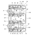
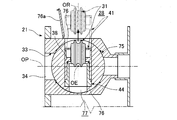
- the bit exchanging unit 70 is arranged separately on the left and right sides of the main cutter pork 21 and rotates a rotating valve 75 accommodated in the housing 71 around a tangential axis (rotating axis) OE. 31 is exchanged from above or below.
- the bit exchange unit 70 is disposed on the main cutter pork 21 with an interval L in the radial axis (insertion / removal axis) OR direction for shifting the excavation position and for the internal work space 28.
- the left and right roller bits 31 are arranged at staggered positions that are displaced in the radial direction when the main cutter pork 21 is viewed from the front.
- a bit accommodation passage 33 formed through the housing 71 is formed with a bit accommodation portion 34 and a valve accommodation portion 35 from the front.
- a reaction force support portion 72 is provided integrally with the housing 71 on the back side of the valve housing portion 35.
- a support portion earth removal passage 73 is formed in the axial center portion of the reaction force support portion 72.
- a reaction force receiving portion 76 is integrally formed on the back side of the attaching / detaching passage 38 of the rotation valve 75 so as to prevent the reaction force support block 44 from coming off.
- a communication earth discharge passage 77 is formed in the axial center portion of the reaction force receiving portion 76.
- the excavation reaction force applied to the roller bit 31 is supported from the bit case 41 to the entire rotation valve 75 via the reaction force support block 44 and the reaction force receiving portion 76, and further from the rotation valve 75 to the reaction force support portion. It can be supported by the housing 71 via 72.
- the housing 71 is formed with a replacement opening 74 having an opening / closing door 74a on one side (a surface on the outer peripheral side) in the radial axis OR direction [or on the other side (a surface on the shield axis O side)].
- a valve turning mechanism 51 for turning the turning valve 75 about the tangential axis OE and a roller bit 31 are provided at the excavation position.
- the turning valve 75 is retracted from the bit accommodating portion 34 at the excavation position into the attaching / detaching passage 38 at the retracted position by the bit retracting mechanism 54, and further the valve rotating mechanism 51.
- the rotation valve 75 is rotated 90 ° around the tangential axis OE so that the front surface of the attachment / detachment passage 38 faces the replacement opening 74.
- the bit case 41 can be taken out from the replacement opening 74 to the work space 28 as in the modification of the first embodiment.
- bit exchange units 70 can be arranged on the main cutter pork 21, which is suitable for a large excavator.
Landscapes
- Engineering & Computer Science (AREA)
- Mining & Mineral Resources (AREA)
- Environmental & Geological Engineering (AREA)
- Life Sciences & Earth Sciences (AREA)
- General Life Sciences & Earth Sciences (AREA)
- Geochemistry & Mineralogy (AREA)
- Geology (AREA)
- Excavating Of Shafts Or Tunnels (AREA)
Abstract
Description
カッタヘッドの前部にハウジングを設置し、
当該ハウジングに、前記ローラビットを出退する出退軸線に沿ってビット収容通路を形成し、
当該ビット収容通路に、カッタヘッドの前面に開口するビット収容部と、後部に形成されたバルブ収容部を設け、
前記ハウジングに、前記出退軸線に対して所定角度隔てた挿脱軸線方向に、前記バルブ収容部と前記作業空間とを連通する交換用開口部を形成し、
前記バルブ収容部内に、前記出退軸線および前記挿脱軸線に略直交する回動軸線周りに回動自在な回動バルブを設け、
当該回動バルブに、前記ビット収容部に連通する着脱通路を形成し、
当該着脱通路内に、前記ローラビットを有する前記ビットケースを挿脱自在に配置し、
前記回動バルブを所定角度回動させて前記着脱通路を前記交換用開口部に連通させることにより、前記着脱通路と前記作業空間の間でビットケースを挿脱可能とし、
前記回動バルブに、前記ビットケースを前記着脱通路と前記ビット収容部との間で出退移動させるビット出退機構を設け、
前記ビットケースと前記バルブ収容部との隙間を止水する第1シール材を設け、
前記回動バルブの外周面で前記着脱通路の開口部周囲と前記バルブ収容部の内面との隙間を止水する第2シール材を設けたものである。
前記回動バルブの前記着脱通路で前記ビットケースの背面側に、前記ローラビットの掘削反力を前記ハウジングに伝達して支持させる反力支持ブロックを設け、
前記バルブ収容部内で前記ビットケースと前記反力支持ブロックとの間に、掘削反力を伝達するコッタ部材を嵌脱自在に設けたものである。
前記ビット収容通路を、前記カッタヘッドを貫通して形成し、
前記着脱通路を、前記回動バルブを貫通して形成し、
前記反力支持ブロックを前記着脱通路に挿脱自在に配置し、
前記反力支持ブロックを、前記回動バルブの前記着脱通路の背面開口部から前記交換用開口部を介して前記作業空間に挿脱自在としたものである。
前記ビットケースに、前記ローラビットを収容するケース排土通路を前記出退軸線方向に貫通形成し、
前記反力支持ブロックに、前記ケース排土通路に連通するブロック排土通路を前記出退軸線方向に貫通形成し、
前記ローラビットにより掘削された掘削物を前記ケース排土通路から前記ブロック排土通路を介して前記カッタヘッドの背面側に排出可能に構成したものである。
[実施例1]
以下、本発明に係るシールド掘進機(掘削機)のビット交換装置であるビット交換ユニットの実施例を説明する。
図12に示すように、円筒形のシールド本体(掘削機本体)11の前部に、切羽崩壊土圧を保持する圧力隔壁12が設けられており、この圧力隔壁12に旋回軸受13を介して旋回リング体14が、掘削機軸線であるシールド軸心O周りに回転自在に支持されている。そして、この旋回リング体14に複数の支持脚15が前方に突設され、これら支持脚15の前端部に円形のカッタヘッド16が支持されている。圧力隔壁12の後部に、大気圧に保持された大気圧室19が形成され、この大気圧室19に、カッタヘッド16を回転駆動するカッタ駆動装置17が設けられている。このカッタ駆動装置17は、旋回リング体14の背面に設けられたリングギヤ17aと、このリングギヤ17aに噛み合う複数の駆動ピニオン17bと、前記駆動ピニオン17bをそれぞれ回転駆動する複数の回転駆動装置(油圧式または電動式モータ)17cとで構成されている。さらに圧力隔壁12に、カッタヘッド16により掘削された土砂を、切羽崩壊土圧を保持しつつ圧力隔壁12の前部から大気圧室19側に排出する排土用スクリュコンベヤ装置18が設けられている。
図1~図10、図13~図16を参照して、ビット交換ユニットの第1実施例を説明する。
前記着脱通路38に、図8に示すように、ローラビット31を収容したビットケース41と、このローラビット31からビットケース41を介して加わる掘削反力を反力支持プラグ32Eからハウジング32に支持させる反力支持ブロック44とがそれぞれ挿脱自在に配置される。
このビット交換ユニット31には、図1,図5、図7に示すように、ハウジング32に設けられて回動バルブ39を使用姿勢と交換姿勢との間で回動させるバルブ回動機構51と、回動バルブ39に設けられて掘削位置と着脱通路38内の後退位置との間でビットケース41を出退駆動するビット出退機構55が設けられている。
このビット交換ユニット30は、図4および図10に示すように、複数のシール材により止水されて作業空間28への漏水が防止されている。
上記構成におけるローラビット31の交換手順を説明する。
図17は、実施例1における回動バルブ39の回動方向を、逆方向に90°回動させるように構成したもので、ビットケース41から先に、ビットケース41のみを取り出すことができる。なお、ビットケース41の交換時にカムローラ43が障害となるが、ビット出退機構55の出退用カム軸57を取り外した後に、カムローラ43を取り外すことにより、これを解消することができる。この変形例では、反力支持ブロック44を回動バルブ39に固定したり、反力支持ブロック44と回動バルブ39とを一体に成形することもできる。
ビット交換ユニットの第2実施例を、図18~図20に基づいて説明する。なお、第1実施例と同一部材には同一符号を付して説明を省略する。
Claims (4)
- 掘削機本体の前部に、掘削機軸線周りに回転自在に支持されたカッタヘッドと、当該カッタヘッドの前面に配置されて岩盤や礫を破砕するローラビットと、前記カッタヘッド内に形成されて、磨耗した前記ローラビットを交換可能な作業空間とを具備した掘削機のビット交換装置であって、
カッタヘッドの前部にハウジングを設置し、
当該ハウジングに、前記ローラビットを出退する出退軸線に沿ってビット収容通路を形成し、
当該ビット収容通路に、カッタヘッドの前面に開口するビット収容部と、後部に形成されたバルブ収容部を設け、
前記ハウジングに、前記出退軸線に対して所定角度隔てた挿脱軸線方向に、前記バルブ収容部と前記作業空間とを連通する交換用開口部を形成し、
前記バルブ収容部内に、前記出退軸線および前記挿脱軸線に略直交する回動軸線周りに回動自在な回動バルブを設け、
当該回動バルブに、前記ビット収容部に連通する着脱通路を形成し、
当該着脱通路内に、前記ローラビットを有する前記ビットケースを挿脱自在に配置し、
前記回動バルブを所定角度回動させて前記着脱通路を前記交換用開口部に連通させることにより、前記着脱通路と前記作業空間の間でビットケースを挿脱可能とし、
前記回動バルブに、前記ビットケースを前記着脱通路と前記ビット収容部との間で出退移動させるビット出退機構を設け、
前記ビットケースと前記バルブ収容部との隙間を止水する第1シール材を設け、
前記回動バルブの外周面で前記着脱通路の開口部周囲と前記バルブ収容部の内面との隙間を止水する第2シール材を設けた
ことを特徴とする掘削機のビット交換装置。 - 前記回動バルブの前記着脱通路で前記ビットケースの背面側に、前記ローラビットの掘削反力を前記ハウジングに伝達して支持させる反力支持ブロックを設け、
前記バルブ収容部内で前記ビットケースと前記反力支持ブロックとの間に、掘削反力を伝達するコッタ部材を嵌脱自在に設けた
ことを特徴とする請求項1記載の掘削機のビット交換装置。 - 前記ビット収容通路を、前記カッタヘッドを貫通して形成し、
前記着脱通路を、前記回動バルブを貫通して形成し、
前記反力支持ブロックを前記着脱通路に挿脱自在に配置し、
前記反力支持ブロックを、前記回動バルブの前記着脱通路の背面開口部から前記交換用開口部を介して前記作業空間に挿脱自在とした
ことを特徴とする請求項1または2記載の掘削機のビット交換装置。 - 前記ビットケースに、前記ローラビットを収容するケース排土通路を前記出退軸線方向に貫通形成し、
前記反力支持ブロックに、前記ケース排土通路に連通するブロック排土通路を前記出退軸線方向に貫通形成し、
前記ローラビットにより掘削された掘削物を前記ケース排土通路から前記ブロック排土通路を介して前記カッタヘッドの背面側に排出可能に構成した
ことを特徴とする請求項3記載の掘削機のビット交換装置。
Priority Applications (5)
| Application Number | Priority Date | Filing Date | Title |
|---|---|---|---|
| US13/520,352 US8540319B2 (en) | 2010-01-29 | 2010-12-16 | Bit replacing device for excavating machine |
| KR1020127013009A KR101680553B1 (ko) | 2010-01-29 | 2010-12-16 | 굴삭기의 비트 교환장치 |
| SG2012048203A SG181980A1 (en) | 2010-01-29 | 2010-12-16 | Bit-replacing device for excavating machine |
| CN201080053948.3A CN102639813B (zh) | 2010-01-29 | 2010-12-16 | 挖掘机的刀头更换装置 |
| HK12109975.6A HK1169153B (en) | 2010-01-29 | 2010-12-16 | Bit-replacing device for excavator |
Applications Claiming Priority (2)
| Application Number | Priority Date | Filing Date | Title |
|---|---|---|---|
| JP2010-017520 | 2010-01-29 | ||
| JP2010017520A JP5355439B2 (ja) | 2010-01-29 | 2010-01-29 | 掘削機のビット交換装置 |
Publications (1)
| Publication Number | Publication Date |
|---|---|
| WO2011092964A1 true WO2011092964A1 (ja) | 2011-08-04 |
Family
ID=44318962
Family Applications (1)
| Application Number | Title | Priority Date | Filing Date |
|---|---|---|---|
| PCT/JP2010/072604 Ceased WO2011092964A1 (ja) | 2010-01-29 | 2010-12-16 | 掘削機のビット交換装置 |
Country Status (6)
| Country | Link |
|---|---|
| US (1) | US8540319B2 (ja) |
| JP (1) | JP5355439B2 (ja) |
| KR (1) | KR101680553B1 (ja) |
| CN (1) | CN102639813B (ja) |
| SG (1) | SG181980A1 (ja) |
| WO (1) | WO2011092964A1 (ja) |
Families Citing this family (18)
| Publication number | Priority date | Publication date | Assignee | Title |
|---|---|---|---|---|
| JP5730163B2 (ja) * | 2011-09-06 | 2015-06-03 | 日立造船株式会社 | シールド掘進機の掘削ビット交換装置および掘削ビット交換方法 |
| JP5769567B2 (ja) | 2011-09-27 | 2015-08-26 | 日立造船株式会社 | シールド掘進機の掘削ビット交換装置 |
| JP5889645B2 (ja) * | 2012-01-24 | 2016-03-22 | 日立造船株式会社 | シールド掘進機のビット交換方法および装置 |
| FR3012843B1 (fr) * | 2013-11-04 | 2018-10-26 | Bouygues Travaux Publics | Porte-outil de coupe pour un tunnelier et ensemble de coupe associe |
| CN103726855B (zh) * | 2014-01-21 | 2016-02-03 | 中铁隧道集团有限公司 | 一种滚刀常压换刀装置 |
| DE102014110310A1 (de) * | 2014-07-22 | 2016-01-28 | Herrenknecht Aktiengesellschaft | Schneidrollenanordnung und mit Schneidrollenanordnungen ausgestattetes Schneidrad |
| JP6575164B2 (ja) * | 2015-06-19 | 2019-09-18 | 日本シビックコンサルタント株式会社 | カッタ装置及びこれを用いたトンネル掘進機 |
| CN105464677A (zh) * | 2015-12-31 | 2016-04-06 | 卢兴耐 | T形顶管掘进机 |
| CN105855849B (zh) * | 2016-04-14 | 2017-12-01 | 东北大学 | 一种盾构机单滚刀换刀机械手 |
| CN106499401B (zh) * | 2016-12-19 | 2019-04-05 | 中交隧道工程局有限公司 | 一种超大直径盾构机常压换刀装置及方法 |
| CN106593461B (zh) * | 2017-02-14 | 2018-06-26 | 东北大学 | 一种盾构机盘形滚刀的刀箱机构及其使用方法 |
| JP7094180B2 (ja) * | 2018-08-29 | 2022-07-01 | Jimテクノロジー株式会社 | トンネル掘削機 |
| JP7307664B2 (ja) * | 2019-11-26 | 2023-07-12 | 日本シビックコンサルタント株式会社 | トンネル掘進機のカッタービット交換装置 |
| JP7556701B2 (ja) * | 2020-05-25 | 2024-09-26 | 株式会社小松製作所 | トンネル掘削装置 |
| CN112855198B (zh) * | 2021-01-30 | 2022-11-22 | 安徽唐兴装备科技股份有限公司 | 一种便于更换刀头的刀盘及应用该刀盘的顶管机 |
| CN112682059B (zh) * | 2021-01-30 | 2024-06-04 | 安徽唐兴装备科技股份有限公司 | 一种带半圆挡块的盘形刀盘及应用该刀盘的顶管机 |
| CN113231801B (zh) * | 2021-05-28 | 2022-09-13 | 安徽唐兴装备科技股份有限公司 | 一种更换顶管机刀头的机械装置 |
| CN114294005B (zh) * | 2021-12-28 | 2024-05-14 | 中铁工程装备集团有限公司 | 刀具装置、掘进机械以及换刀方法 |
Citations (3)
| Publication number | Priority date | Publication date | Assignee | Title |
|---|---|---|---|---|
| JP2000096987A (ja) * | 1998-09-18 | 2000-04-04 | Kawasaki Heavy Ind Ltd | シールド掘進機用カッター装置 |
| JP2002276290A (ja) * | 2001-03-16 | 2002-09-25 | Komatsu Ltd | シールド掘進機のカッタヘッド |
| JP2004218298A (ja) * | 2003-01-16 | 2004-08-05 | Mitsubishi Heavy Ind Ltd | カッタ移動装置及び方法とカッタ交換方法とトンネル掘削機 |
Family Cites Families (14)
| Publication number | Priority date | Publication date | Assignee | Title |
|---|---|---|---|---|
| US4193637A (en) * | 1978-08-07 | 1980-03-18 | The Robbins Company | Rotary cutterhead for an earth boring machine |
| US4234235A (en) * | 1979-02-05 | 1980-11-18 | The Robbins Company | Rotary cutterhead for an earth boring machine |
| JPH03139749A (ja) | 1989-10-26 | 1991-06-13 | Fujitsu Ltd | 入出力装置制御方式 |
| JPH04163965A (ja) | 1990-10-29 | 1992-06-09 | Fujitsu Ltd | 半導体装置の製造方法 |
| SG102583A1 (en) * | 1999-07-14 | 2004-03-26 | Mitsubishi Heavy Ind Ltd | Method for replacing cutters of tunnel-excavating machine, method for excavating tunnel, and tunnel-excavating machine |
| JP3692267B2 (ja) * | 1999-12-15 | 2005-09-07 | 三菱重工業株式会社 | カッタヘッド |
| JP2003106092A (ja) * | 2001-10-02 | 2003-04-09 | Hitachi Constr Mach Co Ltd | ローラビット装置 |
| JP4163965B2 (ja) | 2003-01-08 | 2008-10-08 | 三菱重工地中建機株式会社 | トンネル掘削機 |
| CN100491694C (zh) * | 2005-03-21 | 2009-05-27 | 上海隧道工程股份有限公司 | 机内可拆换式盾构刀盘驱动装置及其拆换方法 |
| CN100519989C (zh) * | 2005-08-17 | 2009-07-29 | 上海市基础工程公司 | 复合式平衡盾构机 |
| SE531726C2 (sv) * | 2006-10-30 | 2009-07-21 | Atlas Copco Rock Drills Ab | Anordning och metod för att automatiskt byte av en borrkrona på en borrstång samt dataprogramprodukt och bergborrigg försedd med anordningen |
| CN201241708Y (zh) * | 2008-08-20 | 2009-05-20 | 刘玉海 | 盾构机用滚刀 |
| JP5091077B2 (ja) * | 2008-10-03 | 2012-12-05 | 川崎重工業株式会社 | カッタビット交換装置 |
| CN101440710B (zh) * | 2008-12-23 | 2010-12-01 | 沈阳重型机械集团有限责任公司 | 盾构机滚刀背装式自定位固定装置 |
-
2010
- 2010-01-29 JP JP2010017520A patent/JP5355439B2/ja active Active
- 2010-12-16 CN CN201080053948.3A patent/CN102639813B/zh not_active Expired - Fee Related
- 2010-12-16 WO PCT/JP2010/072604 patent/WO2011092964A1/ja not_active Ceased
- 2010-12-16 KR KR1020127013009A patent/KR101680553B1/ko not_active Expired - Fee Related
- 2010-12-16 US US13/520,352 patent/US8540319B2/en not_active Expired - Fee Related
- 2010-12-16 SG SG2012048203A patent/SG181980A1/en unknown
Patent Citations (3)
| Publication number | Priority date | Publication date | Assignee | Title |
|---|---|---|---|---|
| JP2000096987A (ja) * | 1998-09-18 | 2000-04-04 | Kawasaki Heavy Ind Ltd | シールド掘進機用カッター装置 |
| JP2002276290A (ja) * | 2001-03-16 | 2002-09-25 | Komatsu Ltd | シールド掘進機のカッタヘッド |
| JP2004218298A (ja) * | 2003-01-16 | 2004-08-05 | Mitsubishi Heavy Ind Ltd | カッタ移動装置及び方法とカッタ交換方法とトンネル掘削機 |
Also Published As
| Publication number | Publication date |
|---|---|
| JP5355439B2 (ja) | 2013-11-27 |
| HK1169153A1 (en) | 2013-01-18 |
| JP2011157683A (ja) | 2011-08-18 |
| KR20130001207A (ko) | 2013-01-03 |
| CN102639813B (zh) | 2014-05-21 |
| KR101680553B1 (ko) | 2016-11-29 |
| US8540319B2 (en) | 2013-09-24 |
| SG181980A1 (en) | 2012-08-30 |
| CN102639813A (zh) | 2012-08-15 |
| US20120274122A1 (en) | 2012-11-01 |
Similar Documents
| Publication | Publication Date | Title |
|---|---|---|
| JP5355439B2 (ja) | 掘削機のビット交換装置 | |
| JP5889645B2 (ja) | シールド掘進機のビット交換方法および装置 | |
| JP5058218B2 (ja) | 掘削機のビット交換装置 | |
| JP3692267B2 (ja) | カッタヘッド | |
| JP6575164B2 (ja) | カッタ装置及びこれを用いたトンネル掘進機 | |
| JP6445336B2 (ja) | ローラーカッター交換装置及びローラーカッター交換方法 | |
| JP4143911B2 (ja) | シールド掘進機のカッタビット交換方法および装置 | |
| JP2000034889A (ja) | カッタ装置及びトンネル掘削機 | |
| JP3785030B2 (ja) | トンネル掘削機 | |
| JP4061732B2 (ja) | シールド掘進機 | |
| JP4841365B2 (ja) | シールド掘進機の掘削用ビット交換装置 | |
| JP4433601B2 (ja) | カッタビット交換構造 | |
| JP4138626B2 (ja) | トンネル掘削機及びトンネル掘削機のカッタ交換方法 | |
| JP2022048035A (ja) | トンネル掘削機、掘削ツール交換装置および掘削ツール交換方法 | |
| JP7307664B2 (ja) | トンネル掘進機のカッタービット交換装置 | |
| JP3634625B2 (ja) | カッタ装置及びトンネル掘削機 | |
| JP2004251042A (ja) | トンネル掘削機 | |
| HK1169153B (en) | Bit-replacing device for excavator | |
| JP4842466B2 (ja) | トンネル掘削機 | |
| JP4635240B2 (ja) | シールド掘進機のビット交換装置 | |
| JP3832005B2 (ja) | シールド掘進機 | |
| JP3775702B2 (ja) | シールド掘進機のドレーン材切断装置およびドレーン材切断装置のブレードカッタ交換方法 | |
| JP3917891B2 (ja) | トンネル掘削機 | |
| JP3759015B2 (ja) | 地中接合式トンネル掘削機 | |
| HK1165523B (en) | Bit replacing device for excavating machine |
Legal Events
| Date | Code | Title | Description |
|---|---|---|---|
| WWE | Wipo information: entry into national phase |
Ref document number: 201080053948.3 Country of ref document: CN |
|
| 121 | Ep: the epo has been informed by wipo that ep was designated in this application |
Ref document number: 10844718 Country of ref document: EP Kind code of ref document: A1 |
|
| ENP | Entry into the national phase |
Ref document number: 20127013009 Country of ref document: KR Kind code of ref document: A |
|
| WWE | Wipo information: entry into national phase |
Ref document number: 1598/KOLNP/2012 Country of ref document: IN |
|
| WWE | Wipo information: entry into national phase |
Ref document number: 13520352 Country of ref document: US |
|
| WWE | Wipo information: entry into national phase |
Ref document number: 2012/08644 Country of ref document: TR |
|
| NENP | Non-entry into the national phase |
Ref country code: DE |
|
| 122 | Ep: pct application non-entry in european phase |
Ref document number: 10844718 Country of ref document: EP Kind code of ref document: A1 |