WO2011089697A1 - 非水電解質電池、これに用いる正極活物質及びその製造方法 - Google Patents
非水電解質電池、これに用いる正極活物質及びその製造方法 Download PDFInfo
- Publication number
- WO2011089697A1 WO2011089697A1 PCT/JP2010/050651 JP2010050651W WO2011089697A1 WO 2011089697 A1 WO2011089697 A1 WO 2011089697A1 JP 2010050651 W JP2010050651 W JP 2010050651W WO 2011089697 A1 WO2011089697 A1 WO 2011089697A1
- Authority
- WO
- WIPO (PCT)
- Prior art keywords
- positive electrode
- composite oxide
- active material
- lithium composite
- electrode active
- Prior art date
- Legal status (The legal status is an assumption and is not a legal conclusion. Google has not performed a legal analysis and makes no representation as to the accuracy of the status listed.)
- Ceased
Links
Images



Classifications
-
- H—ELECTRICITY
- H01—ELECTRIC ELEMENTS
- H01M—PROCESSES OR MEANS, e.g. BATTERIES, FOR THE DIRECT CONVERSION OF CHEMICAL ENERGY INTO ELECTRICAL ENERGY
- H01M4/00—Electrodes
- H01M4/02—Electrodes composed of, or comprising, active material
- H01M4/36—Selection of substances as active materials, active masses, active liquids
- H01M4/48—Selection of substances as active materials, active masses, active liquids of inorganic oxides or hydroxides
- H01M4/485—Selection of substances as active materials, active masses, active liquids of inorganic oxides or hydroxides of mixed oxides or hydroxides for inserting or intercalating light metals, e.g. LiTi2O4 or LiTi2OxFy
-
- H—ELECTRICITY
- H01—ELECTRIC ELEMENTS
- H01M—PROCESSES OR MEANS, e.g. BATTERIES, FOR THE DIRECT CONVERSION OF CHEMICAL ENERGY INTO ELECTRICAL ENERGY
- H01M10/00—Secondary cells; Manufacture thereof
- H01M10/05—Accumulators with non-aqueous electrolyte
- H01M10/052—Li-accumulators
- H01M10/0525—Rocking-chair batteries, i.e. batteries with lithium insertion or intercalation in both electrodes; Lithium-ion batteries
-
- H—ELECTRICITY
- H01—ELECTRIC ELEMENTS
- H01M—PROCESSES OR MEANS, e.g. BATTERIES, FOR THE DIRECT CONVERSION OF CHEMICAL ENERGY INTO ELECTRICAL ENERGY
- H01M4/00—Electrodes
- H01M4/02—Electrodes composed of, or comprising, active material
- H01M4/36—Selection of substances as active materials, active masses, active liquids
- H01M4/48—Selection of substances as active materials, active masses, active liquids of inorganic oxides or hydroxides
- H01M4/50—Selection of substances as active materials, active masses, active liquids of inorganic oxides or hydroxides of manganese
- H01M4/505—Selection of substances as active materials, active masses, active liquids of inorganic oxides or hydroxides of manganese of mixed oxides or hydroxides containing manganese for inserting or intercalating light metals, e.g. LiMn2O4 or LiMn2OxFy
-
- H—ELECTRICITY
- H01—ELECTRIC ELEMENTS
- H01M—PROCESSES OR MEANS, e.g. BATTERIES, FOR THE DIRECT CONVERSION OF CHEMICAL ENERGY INTO ELECTRICAL ENERGY
- H01M4/00—Electrodes
- H01M4/02—Electrodes composed of, or comprising, active material
- H01M4/36—Selection of substances as active materials, active masses, active liquids
- H01M4/48—Selection of substances as active materials, active masses, active liquids of inorganic oxides or hydroxides
- H01M4/52—Selection of substances as active materials, active masses, active liquids of inorganic oxides or hydroxides of nickel, cobalt or iron
- H01M4/525—Selection of substances as active materials, active masses, active liquids of inorganic oxides or hydroxides of nickel, cobalt or iron of mixed oxides or hydroxides containing iron, cobalt or nickel for inserting or intercalating light metals, e.g. LiNiO2, LiCoO2 or LiCoOxFy
-
- Y—GENERAL TAGGING OF NEW TECHNOLOGICAL DEVELOPMENTS; GENERAL TAGGING OF CROSS-SECTIONAL TECHNOLOGIES SPANNING OVER SEVERAL SECTIONS OF THE IPC; TECHNICAL SUBJECTS COVERED BY FORMER USPC CROSS-REFERENCE ART COLLECTIONS [XRACs] AND DIGESTS
- Y02—TECHNOLOGIES OR APPLICATIONS FOR MITIGATION OR ADAPTATION AGAINST CLIMATE CHANGE
- Y02E—REDUCTION OF GREENHOUSE GAS [GHG] EMISSIONS, RELATED TO ENERGY GENERATION, TRANSMISSION OR DISTRIBUTION
- Y02E60/00—Enabling technologies; Technologies with a potential or indirect contribution to GHG emissions mitigation
- Y02E60/10—Energy storage using batteries
Definitions
- the present invention relates to a nonaqueous electrolyte battery, a positive electrode active material used therefor, and a method for producing the same.
- Methods for increasing the energy density include reducing the electrochemical equivalent per unit weight of the electrode active material, lowering the operating potential of the negative electrode active material, and increasing the operating potential of the positive electrode active material.
- a method has been studied in which a positive electrode material having an operating potential close to 5 V with respect to a lithium potential, a so-called 5 V positive electrode material, is used to increase the operating potential of the positive electrode active material and increase the energy density.
- a material represented by the chemical formula LiNi 0.5 Mn 1.5 O 4 is known as a 5V positive electrode material (Non-patent Document 1).
- a battery using this LiNi 0.5 Mn 1.5 O 4 as a positive electrode active material has a problem that the cycle performance is insufficient for practical use.
- Patent Document 1 tries to improve the material, and has the chemical formula Li y Ni 0.5-x Mn 1.5 + x O 4- ⁇ (0.9 ⁇ y ⁇ 1.1, 0 ⁇ x ⁇ 0.1, ⁇ > 0),
- a spinel structure compound having a lattice constant of 8.167 to 8.190 is disclosed (claim 1).
- Patent Document 2 provides a non-aqueous electrolyte secondary battery in which rate characteristics, cycle performance, safety and storage stability are improved by examining and optimizing the battery design (paragraph 0014). However, further improvement is necessary for practical use.
- An object of the present invention is to provide a positive electrode active material for a nonaqueous electrolyte battery having a large energy density and excellent cycle performance, and a method for producing the same. Moreover, it aims at providing the nonaqueous electrolyte battery using the positive electrode containing this positive electrode active material.
- the present invention has a spinel structure and Li x Ni y Mn 2 -yz M z O 4 -b (0.9 ⁇ x ⁇ 1.15, 0.51 ⁇ y ⁇ 0.65, 0 ⁇ z ⁇ 0.1, 0 ⁇ b ⁇ 0.3, M represents at least one element selected from the group consisting of Co, Mg, Al, Si, Ti, Zn, Zr, Ti, Ca and Sn), and the following (I) Provided is a positive electrode active material for a non-aqueous electrolyte battery comprising a lithium composite oxide satisfying the formula; 2.1 ⁇ I (111) / I (311) ⁇ 2.7 (I)
- I (111) is the maximum diffraction peak intensity attributed to the (111) plane of the lithium composite oxide by the powder X-ray diffraction method using CuK ⁇ as the radiation source
- I (311) is CuK ⁇ as the radiation source. Is the maximum diffraction peak intensity attributed to the (31)
- the second aspect of the present invention has a spinel structure and Li x Ni y Mn 2 -yz M z O 4 -b (0.9 ⁇ x ⁇ 1.15, 0.38 ⁇ y ⁇ 0.45, 0 ⁇ z ⁇ 0.1, 0 ⁇ b ⁇ 0.3, M represents at least one element selected from the group consisting of Co, Mg, Al, Si, Ti, Zn, Zr, Ti, Ca, and Sn).
- Dispersing in a solution containing Ni ions Irradiating the solution in which the lithium composite oxide is dispersed with an ultrasonic wave having an output of 50 W to 500 W and a frequency of 10 kHz to 1000 kHz; A method for producing a positive electrode active material for a non-aqueous electrolyte battery is provided.
- a nonaqueous electrolyte battery comprising a positive electrode including the positive electrode active material, a negative electrode, and a nonaqueous electrolyte.
- a positive electrode active material for a nonaqueous electrolyte battery having a large energy density and excellent cycle performance, and a method for producing the same are provided. Moreover, the nonaqueous electrolyte battery using the positive electrode containing this positive electrode active material is provided.
- the partial notch perspective view of a flat type nonaqueous electrolyte battery The expanded sectional view of the A section of FIG.
- the positive electrode active material for a non-aqueous electrolyte battery according to the first embodiment has a spinel structure, and Li x Ni y Mn 2 -yz M z O 4 -b (0.9 ⁇ x ⁇ 1.15, 0.51 ⁇ y ⁇ 0.65, 0 ⁇ z ⁇ 0.1, 0 ⁇ b ⁇ 0.3, M represents at least one element selected from the group consisting of Co, Mg, Al, Si, Ti, Zn, Zr, Ti, Ca and Sn) And a lithium composite oxide satisfying the following formula (I).
- I (111) is the maximum diffraction peak intensity attributed to the (111) plane of the lithium composite oxide by the powder X-ray diffraction method using CuK ⁇ as the radiation source
- I (311) is CuK ⁇ as the radiation source.
- the chemical composition of the lithium composite oxide is obtained by ICP emission spectroscopic analysis.
- the chemical composition is Li x Ni y Mn 2-yz M z O 4-b (0.9 ⁇ x ⁇ 1.15, 0.51 ⁇ y ⁇ 0.65, 0 ⁇ z ⁇ 0.1, 0 ⁇ b ⁇ 0.3, M is Co, Mg, Al,
- the spinel-structure lithium composite oxide (which represents at least one element selected from the group consisting of Si, Ti, Zn, Zr, Ti, Ca, and Sn) is obtained by replacing part of Mn with Ni It is.
- Ni is divalent and Mn is trivalent or tetravalent.
- the energy density is high and the cycle performance is improved. It is possible to provide an excellent positive electrode active material.
- the value of the lattice constant a is preferably in the range of 0.813 to 0.8159.
- the lattice constant a represents the distance between atoms. Since Ni atoms are smaller than Mn atoms, when Mn is replaced by Ni, the lattice constant a becomes small.
- the chemical composition is obtained by ICP emission spectroscopic analysis, the case where Ni adheres to the particle surface is included, but the value of the lattice constant a is 0.8159 or less, so that Mn is substituted by Ni. I understand.
- the value of the lattice constant a is 0.813 or more, the crystal structure of the lithium composite oxide does not change and the cycle performance is good.
- a method for producing a lithium composite oxide used for the positive electrode active material for a nonaqueous electrolyte battery according to the first embodiment will be described in detail below.
- it has a spinel structure, and Li x Ni y Mn 2 -yz M z O 4 -b (0.9 ⁇ x ⁇ 1.15, 0.38 ⁇ y ⁇ 0.45, 0 ⁇ z ⁇ 0.1, 0 ⁇ b ⁇ 0.3).
- M represents at least one element selected from the group consisting of Co, Mg, Al, Si, Ti, Zn, Zr, Ti, Ca, and Sn).
- the raw material lithium composite oxide ” is dispersed in a solution containing Ni ions and subjected to ultrasonic treatment.
- the raw material lithium composite oxide may be produced by a known method. Or you may produce by arbitrary methods prior to ultrasonic processing. According to the solid phase method, a raw material lithium composite oxide having a spinel structure and a desired chemical composition can be advantageously produced.
- a lithium source, a manganese source, and a nickel source compound are mixed at a predetermined ratio and heated to prepare a raw material lithium composite oxide.
- Li 2 CO 3 , MnO 2 and Ni (OH) 2 weighed so as to have a composition of LiMn 1.52 Ni 0.48 O 4 are wet-mixed and calcined (for example, 600 ° C., oxygen flow, 24 hours).
- the obtained powder is subjected to main baking (for example, 700 ° C., oxygen flow, 24 hours).
- the raw material lithium composite oxide powder thus obtained has, for example, a chemical composition determined by ICP emission analysis of LiMn 1.52 Ni 0.48 O 4 , and a peak intensity I (111 determined by powder X-ray diffraction method. ) / I (311) was 1.69.
- the raw material lithium composite oxide is dispersed in a solution containing Ni ions.
- the solution containing Ni ions may be any solution, but is preferably a weakly acidic solution.
- the Ni ion concentration in the solution is preferably in the range of 0.1 to 20 weight percent.
- the Ni ion source can use an inorganic acid or an organic acid containing Ni, but is not limited thereto.
- nickel (II) acetate tetrahydrate can be used.
- the solvent may be any solvent as long as nickel is ionized.
- purified water can be used.
- the solution in which the raw material lithium composite oxide is dispersed is subjected to ultrasonic treatment.
- a solution in which the raw material lithium composite oxide powder is dispersed is placed in a container, and the container is irradiated with ultrasonic waves.
- the raw material lithium composite oxide can be modified by ultrasonic treatment. As the modification proceeds, the intensity of the main peak I (111) in the powder X-ray diffraction method increases, and the peak intensity ratio I (111) / I (311) increases accordingly. Therefore, a lithium composite oxide having a desired peak intensity ratio can be obtained by appropriately performing ultrasonic treatment.
- the ultrasonic treatment conditions are that the output is 50 W or more and 500 W or less, the frequency is 10 kHz or more and 1000 kHz or less, and the irradiation time is not particularly limited, but is 5 minutes or more and 10 hours or less.
- the output is less than 50 W, there is a possibility that sufficient material modification effect by ultrasonic treatment cannot be obtained.
- the output exceeds 500 W the damage to the particles due to the ultrasonic treatment may be greatly adversely affected.
- the frequency is less than 10 kHz, the number of bubbles generated by ultrasonic waves may be insufficient, and uniform modification may not be performed.
- the upper limit is not particularly limited, but is preferably about 1000 kHz from the viewpoint of practicality.
- the irradiation time is less than 5 minutes, there is a possibility that a homogeneous material modification is not performed and a sufficient effect cannot be obtained.
- the time is longer than 10 hours, the damage to the particles due to the ultrasonic treatment may be greatly adversely affected.
- the value of the lattice constant a decreases as Mn is replaced by Ni.
- the value of the lattice constant a is preferably in the range of 0.813 to 0.8159. It can be seen that when the value of the lattice constant a is in the range of 0.813 or more and 0.8159 or less, the lithium composite oxide is appropriately modified, and a part of Mn is replaced by Ni.
- the solution in which the lithium composite oxide is dispersed is filtered and dried to obtain a spinel structure lithium composite oxide having a desired chemical composition and peak intensity ratio.
- the target lithium composite oxide is packed in a glass sample plate having a depth of 0.2 mm, and measured using a glass plate from the outside, sufficiently pressed and smoothed. At this time, care is taken so that the measurement sample is sufficiently filled in the holder portion, and care is taken so that there is no insufficient filling of the sample such as cracks or voids. Also, the sample should be filled to the same depth (0.2 mm) of the glass holder, and care should be taken not to cause unevenness from the reference surface of the glass holder due to excessive or insufficient filling amount.
- an electrode containing a conductive agent and a binder described later in addition to measurement as a powder.
- a slurry prepared by suspending a lithium composite oxide powder, a binder, and a conductive agent in a widely used solvent is applied to an electrode current collector and dried to prepare an electrode layer Then, an electrode is manufactured by pressing.
- a similar diffraction pattern can be measured even when the electrode thus prepared is subjected to X-ray diffraction measurement.
- a similar diffraction pattern can also be measured by disassembling the nonaqueous electrolyte battery, taking out the electrode, washing it with, for example, methyl ethyl carbonate, and subjecting it to an X-ray diffraction measurement.
- the measurement conditions of the powder X-ray diffractometer with a Cu-K ⁇ radiation source were measured with a scanning speed of 3 deg / min, step width of 0.2 deg, tube voltage of 40 kV, and tube current of 20 mA as standard. Therefore, it is desirable to change the conditions so that sufficient peak intensity can be obtained.
- the lattice constant a was calculated from the peak position information obtained using commercially available software (for example, JADE manufactured by Rigaku), and the initial value of the lattice constant was calculated. Using the obtained initial values, the lattice constant was refined by the Rietveld method.
- the nonaqueous electrolyte battery according to the third embodiment includes a positive electrode including a positive electrode active material for a nonaqueous electrolyte battery according to the first embodiment, a negative electrode, a nonaqueous electrolyte, a separator, and an exterior material.
- the specific surface area Ac [m 2 / g] of the positive electrode and the specific surface area Aa [m 2 / g] of the negative electrode preferably satisfy the following formula (II). 2 ⁇ Aa / Ac ⁇ 8 (II)
- the specific surface area of each electrode is measured by a mercury intrusion method.
- the specific surface area of the electrode When the specific surface area of the electrode is increased, the intended battery reaction is promoted while the side reaction is also promoted. Therefore, in the positive electrode, it is preferable to make the specific surface area relatively small in order to suppress elution of the metal component. On the other hand, in the negative electrode, it is preferable to make the specific surface area relatively large in order to promote the battery reaction. In the negative electrode operating at 1 V or more with respect to Li described above, the reduction reaction is unlikely to occur, so the effect of improving the battery performance by increasing the specific surface area is more easily obtained.
- the positive electrode the negative electrode, the nonaqueous electrolyte, the separator, and the exterior material will be described in detail.
- the positive electrode includes a current collector and a positive electrode layer (positive electrode active material-containing layer) formed on one or both surfaces of the current collector and including an active material, a conductive agent, and a binder.
- a positive electrode layer positive electrode active material-containing layer formed on one or both surfaces of the current collector and including an active material, a conductive agent, and a binder.
- the active material is a battery active material containing the lithium composite oxide described in the first embodiment.
- the lithium composite oxide has a spinel structure, and Li x Ni y Mn 2 -yz M z O 4 -b (0.9 ⁇ x ⁇ 1.15, 0.51 ⁇ y ⁇ 0.65, 0 ⁇ z ⁇ 0.1, 0 ⁇ b ⁇ 0.3, M represents at least one element selected from the group consisting of Co, Mg, Al, Si, Ti, Zn, Zr, Ti, Ca and Sn), and the following formula (I) It is a lithium composite oxide that fills.
- I (111) is the maximum diffraction peak intensity attributed to the (111) plane of the lithium composite oxide by the powder X-ray diffraction method using CuK ⁇ as the radiation source
- I (311) is CuK ⁇ as the radiation source.
- the lithium composite oxide preferably has a value of the lattice constant a in the range of 0.813 to 0.8159.
- a positive electrode using such an active material containing a lithium composite oxide can improve the energy density of the nonaqueous electrolyte battery and improve the cycle performance.
- the active material As the active material, the active material according to the first embodiment may be used alone, or may be used as a mixture with other active materials. However, 40% by weight or more of the total active material weight is preferably the spinel structure active material. Thereby, the effect of increasing the energy density can be sufficiently obtained. A more preferable content of the spinel structure active material is 60 to 100% by weight with respect to the total weight of the active material.
- Examples of other active materials include manganese dioxide (MnO 2 ), iron oxide, copper oxide, nickel oxide, Li a MnO 2 , lithium cobalt composite oxide (Li a CoO 2 ), lithium manganese cobalt composite oxide (for example, , LiMn 1-gh Co g M h O 2 , where M is at least one element selected from the group consisting of Al, Cr, Mg and Fe, 0 ⁇ g ⁇ 0.5, 0 ⁇ h ⁇ 0.1), lithium manganese nickel composite oxide (for example, LiMn j Ni j M 1-2j O 2 , where M is at least one or more selected from the group consisting of Co, Cr, Al, Mg and Fe) 1/3 ⁇ j ⁇ 1/2, LiMn 1/3 Ni 1/3 Co 1/3 O 2 , LiMn 1/2 Ni 1/2 O 2 ), spinel type lithium manganese composite oxide (for example, li a Mn 2-b M b O 4, wherein M is Al, C , At least one or two or more
- Li a FePO 4, Li a Fe 1-b Mn b PO 4, Li a CoPO 4 or the like), iron sulfate (Fe 2 (SO 4 ) 3 ), or vanadium oxide (eg, V 2 O 5 ) can be used.
- a and b are each preferably 0 to 1.1.
- conductive polymer materials such as polyaniline and polypyrrole, disulfide polymer materials, organic materials such as sulfur (S) and carbon fluoride, and inorganic materials can be used.
- More preferable positive electrode active materials include lithium cobalt composite oxide, lithium manganese nickel composite oxide, spinel type lithium manganese composite oxide, lithium manganese cobalt composite oxide, and lithium iron phosphate.
- the conductive agent is blended as necessary in order to enhance the current collecting performance and suppress the contact resistance between the active material and the current collector.
- Examples of the conductive agent include carbonaceous materials such as acetylene black, carbon black, and graphite.
- Binding agent binds active material and current collector.
- the binder include polytetrafluoroethylene (PTFE), polyvinylidene fluoride (PVdF), and fluorine-based rubber.
- the active material, the conductive agent and the binder are preferably blended in a proportion of 73 to 95% by weight, 3 to 20% by weight and 2 to 7% by weight, respectively.
- the conductive agent can exert the above-described effects by setting the amount to 3% by weight or more. Moreover, by setting it as 20 weight% or less, decomposition
- a sufficient electrode strength can be obtained by setting the binder to an amount of 2% by weight or more. Moreover, the content of the insulator of an electrode can be reduced by setting it as 7 weight% or less, and internal resistance can be reduced.
- the current collector is preferably an aluminum foil or an aluminum alloy foil containing elements such as Mg, Ti, Zn, Ni, Cr, Mn, Fe, Cu, and Si.
- the aluminum foil or aluminum alloy foil constituting the current collector desirably has an average crystal grain size of 50 ⁇ m or less, more preferably 30 ⁇ m or less, and even more preferably 5 ⁇ m or less.
- the average crystal grain size of the aluminum foil or aluminum alloy foil By setting the average crystal grain size of the aluminum foil or aluminum alloy foil to 50 ⁇ m or less, the strength of the aluminum foil or aluminum alloy foil can be dramatically increased. For this reason, it is possible to increase the positive electrode capacity by increasing the pressure during pressing to increase the density of the positive electrode active material-containing layer.
- the average crystal grain size can be determined by the following method.
- the average crystal particle diameter d ( ⁇ m) is calculated from the obtained S value by the following formula (A).
- the average crystal grain size of the aluminum foil or aluminum alloy foil changes under complex influences from a plurality of factors such as material structure, impurities, processing conditions, heat treatment history, and annealing conditions.
- the crystal grain size can be adjusted by combining the above factors in the production process of the current collector.
- the thickness of the aluminum foil or aluminum alloy foil is desirably 20 ⁇ m or less, more preferably 15 ⁇ m or less.
- the aluminum foil preferably has a purity of 99% by weight or more.
- the content of transition metals such as iron, copper, nickel, and chromium contained in the aluminum foil or aluminum alloy foil is preferably 1% by weight or less.
- the surface of the aluminum foil or aluminum alloy foil is preferably roughened as described above.
- the positive electrode is prepared by suspending an active material, a conductive agent, and a binder in a suitable solvent to prepare a slurry.
- the slurry is applied to a positive electrode current collector and dried to form a positive electrode layer. It is produced by applying.
- the positive electrode may also be produced by forming an active material, a conductive agent and a binder in the form of a pellet to form a positive electrode layer, which is formed on a current collector.
- Negative electrode includes a current collector and a negative electrode layer (negative electrode active material-containing layer) that is formed on one or both surfaces of the current collector and includes an active material, a conductive agent, and a binder.
- the active material for example, a lithium titanium composite oxide, a carbonaceous material, or a metal compound can be used.
- lithium titanium composite oxide examples include spinel type lithium titanate represented by Li 4 + x Ti 5 O 12 ( ⁇ 1 ⁇ x ⁇ 3) or Li 2 + x Ti 3 O 7 ( ⁇ 1 ⁇ a metal complex oxide containing at least one element selected from the group consisting of ramsteride type lithium titanate represented by x ⁇ 3), Ti and P, V, Sn, Cu, Ni and Fe be able to.
- the metal composite oxide includes, for example, TiO 2 —P 2 O 5 , TiO 2 —V 2 O 5 , TiO 2 —P 2 O 5 —SnO 2 , TiO 2 —P 2 O 5 —MeO (Me is Cu, And at least one element selected from the group consisting of Ni and Fe).
- the metal composite oxide preferably has a microstructure with low crystallinity. For example, it is preferable that the crystal phase and the amorphous phase coexist or the amorphous phase exists alone.
- the metal composite oxide having such a microstructure can greatly improve the cycle performance. These metal composite oxides become lithium-titanium composite oxides when lithium is inserted by charging. Of these, spinel type lithium titanate is preferable because of its excellent cycle performance.
- the carbonaceous material for example, natural graphite, artificial graphite, coke, vapor-grown carbon fiber, mesophase pitch-based carbon fiber, spherical carbon, or resin-fired carbon can be used. In particular, it is preferable to use vapor grown carbon fiber, mesophase pitch carbon fiber, and spherical carbon.
- the carbonaceous material preferably has a (002) plane spacing d002 of 0.34 nm or less by powder X-ray diffraction.
- metal sulfide or metal nitride can be used as the metal compound.
- the metal sulfide may be, for example, titanium sulfide such as TiS 2 , molybdenum sulfide such as MoS 2 , iron sulfide such as FeS, FeS 2 , and LixFeS 2 .
- Metal nitride may be, for example, lithium cobalt nitride (e.g. Li s Co t N, 0 ⁇ s ⁇ 4,0 ⁇ t ⁇ 0.5).
- the above active materials may be used alone, or two or more active materials may be mixed and used.
- the nonaqueous electrolyte battery using the positive electrode including the lithium composite oxide according to the first embodiment can operate at a high voltage.
- the higher the positive electrode operating potential the more the transition metal is eluted from the positive electrode active material.
- the transition metal eluted from the positive electrode is deposited on the negative electrode, increasing the negative electrode resistance and degrading the cycle performance. Therefore, the negative electrode active material is preferably capable of inserting and extracting lithium ions at a potential of 1 V or higher with respect to Li.
- a negative electrode active material capable of occluding and releasing lithium ions at a potential of 1 V or higher with respect to Li it is possible to suppress the transition metal eluted from the positive electrode from being deposited on the negative electrode.
- the negative electrode active material is a lithium-ion absorbing and releasable by 1V or more potential to Li
- the above lithium-titanium composite oxide, metal composite oxide it is possible to use a metal sulphide, in particular, Li 4
- a spinel structure lithium titanate such as + x Ti 5 O 12 ( ⁇ 1 ⁇ x ⁇ 3) is preferred.
- Conductive agent enhances the current collection performance of the active material and suppresses contact resistance with the current collector.
- Examples of the conductive agent include carbonaceous materials such as acetylene black, carbon black, and graphite.
- the binder is blended to fill the gap between the dispersed negative electrode active materials, and binds the active material and the conductive agent.
- the binder include polytetrafluoroethylene (PTFE), polyvinylidene fluoride (PVdF), fluorine-based rubber, and styrene butadiene rubber.
- the active material, the conductive agent, and the binder in the negative electrode layer are blended in the range of 73 wt% to 96 wt%, 2 wt% to 20 wt%, and 2 wt% to 7 wt%, respectively. It is preferable.
- the amount of the conductive agent is 2% by weight or more, the current collecting performance of the negative electrode layer is good.
- the amount of the binder is 2% by weight or more, the binding property between the negative electrode layer and the current collector is sufficient, and excellent cycle performance can be expected.
- the current collector is preferably an aluminum foil or an aluminum alloy foil containing elements such as Mg, Ti, Zn, Ni, Cr, Mn, Fe, Cu, and Si.
- the aluminum foil or aluminum alloy foil constituting the current collector desirably has an average crystal grain size of 50 ⁇ m or less, more preferably 30 ⁇ m or less, and still more preferably 5 ⁇ m or less.
- the average crystal grain size can be determined by the method described above.
- the strength of the aluminum foil or aluminum alloy foil can be dramatically increased.
- output characteristics, rapid charging, and charge / discharge cycle performance can also be improved.
- the average crystal grain size of aluminum foil or aluminum alloy foil changes under complex influences from several factors such as material structure, impurities, processing conditions, heat treatment history, and annealing conditions.
- the crystal grain size can be adjusted by combining the above factors in the production process of the current collector.
- the thickness of the aluminum foil or aluminum alloy foil is desirably 20 ⁇ m or less, more preferably 1.50 ⁇ m or less.
- the aluminum foil preferably has a purity of 99% by weight or more.
- the aluminum alloy is preferably an alloy containing elements such as magnesium, zinc, and silicon. Transition metals such as iron, copper, nickel and chromium contained as alloy components are preferably 1% by weight or less.
- the negative electrode for example, a powdered active material, a conductive agent and a binder are suspended in a commonly used solvent to prepare a slurry, and this slurry is applied to a current collector and dried to form a negative electrode layer. Then, it is manufactured by applying a press.
- the negative electrode may also be produced by forming an active material, a conductive agent, and a binder into a pellet shape to form a negative electrode layer on a current collector.
- Nonaqueous electrolyte may be, for example, a liquid nonaqueous electrolyte prepared by dissolving an electrolyte in an organic solvent, or a gelled nonaqueous electrolyte obtained by combining a liquid electrolyte and a polymer material. .
- electrolyte examples include LiPF 6 , LiBF 4 , Li (CF 3 SO 2 ) 2 N (bistrifluoromethanesulfonylamide lithium; commonly known as LiTFSI), LiCF 3 SO 3 (commonly known as LiTFS), and Li (C 2 F 5 SO 2.
- LiBETI bis pentafluoroethanesulfonyl amide lithium; called LiBETI
- LiClO 4 LiAsF 6 , LiSbF 6, bisoxalato Lato lithium borate (LiB (C 2 O 4) 2 ( known as LiBOB))
- difluoro (trifluoro - Lithium salts such as 2-oxide-2-trifluoro-methylpropionate (2-)-0,0) lithium borate (LiBF 2 (OCOOC (CF 3 ) 2 ) (commonly known as LiBF 2 (HHIB))
- LiPF 6 and LiBF 4 are particularly preferred.
- the electrolyte salt concentration is preferably 0.5 to 3 mol / L.
- the electrolyte salt concentration is within such a range, it is possible to further improve the performance when a high load current is passed while suppressing the influence of an increase in viscosity due to an increase in the electrolyte salt concentration.
- organic solvents include, but are not limited to, propylene carbonate (PC), ethylene carbonate (EC), 1,2-dimethoxyethane (DME), ⁇ -butyrolactone (GBL), tetrahydrofuran (THF), 2-methyl Tetrahydrofuran (2-MeHF), 1,3-dioxolane, sulfolane, acetonitrile (AN), diethyl carbonate (DEC), dimethyl carbonate (DMC), methyl ethyl carbonate (MEC), dipropyl carbonate (DPC) are included.
- PC propylene carbonate
- EC ethylene carbonate
- DME 1,2-dimethoxyethane
- GBL ⁇ -butyrolactone
- THF tetrahydrofuran
- 2-MeHF 2-methyl Tetrahydrofuran
- 1,3-dioxolane 1,3-dioxolane
- sulfolane sulfolane
- polymer material examples include polyvinylidene fluoride (PVdF), polyacrylonitrile (PAN), and polyethylene oxide (PEO).
- PVdF polyvinylidene fluoride
- PAN polyacrylonitrile
- PEO polyethylene oxide
- An additive may be added to the nonaqueous electrolyte.
- an additive is not specifically limited, For example, vinylene carbonate (VC), vinylene acetate (VA), vinylene butyrate, vinylene hexanate, vinylene crotonate, catechol carbonate can be used.
- the blending amount of the additive is preferably 0.1 to 3% by weight, more preferably 0.5 to 1% by weight, based on the nonaqueous electrolyte.
- the separator may be formed of, for example, a porous film containing polyethylene, polypropylene, cellulose, or polyvinylidene fluoride (PVdF), or a synthetic resin nonwoven fabric.
- a porous film formed from polyethylene or a polypropylene can melt
- security can be improved.
- Exterior material As the exterior material, a laminate film having a thickness of 0.5 mm or less or a metal container having a thickness of 1 mm or less can be used.
- the thickness of the laminate film is more preferably 0.2 mm or less.
- the metal container is more preferably 0.5 mm or less in thickness, and further preferably 0.2 mm or less in thickness.
- the shape of the exterior material includes a flat type (thin type), a square type, a cylindrical type, a coin type, a button type, and the like.
- Examples of the exterior material include a small battery exterior material loaded on a portable electronic device or the like, and a large battery exterior material loaded on a two-wheeled or four-wheeled vehicle, depending on the battery size.
- the laminate film a multilayer film in which a metal layer is interposed between resin layers is used.
- the metal layer is preferably an aluminum foil or an aluminum alloy foil for weight reduction.
- a polymer material such as polypropylene (PP), polyethylene (PE), nylon, polyethylene terephthalate (PET) can be used.
- PP polypropylene
- PE polyethylene
- PET polyethylene terephthalate
- the laminate film can be molded into the shape of an exterior material by sealing by heat sealing.
- Metal containers are made from aluminum or aluminum alloy.
- the aluminum alloy is preferably an alloy containing elements such as magnesium, zinc, and silicon.
- the alloy contains a transition metal such as iron, copper, nickel, or chromium, the content is preferably 1% by weight or less.
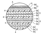
- FIG. 1 is a partially cutaway perspective view of a flat type nonaqueous electrolyte battery, which is an example of a nonaqueous electrolyte battery according to a third embodiment.
- FIG. 2 is an enlarged cross-sectional view of a portion A in FIG.
- Each figure is a schematic diagram for facilitating the explanation and understanding of the invention, and its shape, dimensions, ratio, etc. are different from the actual device, but these are considered in consideration of the following explanation and known techniques. The design can be changed as appropriate.
- the wound electrode group 13 is housed in a metal bottomed rectangular cylindrical outer packaging material 11.
- the flat wound electrode group 13 is formed by winding a laminate of the negative electrode 3, the separator 4, the positive electrode 5, and the separator 4 in this order from the outside in a spiral shape and press-molding. Is done.
- the negative electrode 3 includes a negative electrode current collector 3a and a negative electrode active material layer 3b formed on one surface or both surfaces thereof.
- the positive electrode 5 includes a positive electrode current collector 5a and a positive electrode active material layer 5b formed on one or both surfaces thereof.
- the negative electrode tab 18 has one end connected to the negative electrode current collector 3 a and the other end connected to the negative electrode terminal 20 fixed to the rectangular lid 12 via the negative electrode gasket 21.
- the positive electrode tab 17 has one end connected to the positive electrode current collector 5 a and the other end connected to a positive electrode terminal 19 fixed to the rectangular lid 12.
- the non-aqueous electrolyte is, for example, injected from the opening of the rectangular exterior material 11 and accommodated in the rectangular exterior material 11.
- the wound electrode group 13 and the nonaqueous electrolyte are sealed in the rectangular exterior material 11 by welding the rectangular lid 12 to the opening of the rectangular exterior material 11.
- the negative electrode tab is made of, for example, a material such as aluminum or an aluminum alloy containing elements such as Mg, Ti, Zn, Mn, Fe, Cu, and Si.
- the negative electrode tab is preferably made of the same material as the negative electrode current collector in order to reduce contact resistance with the negative electrode current collector.
- the positive electrode tab is made of, for example, a material such as aluminum or an aluminum alloy containing elements such as Mg, Ti, Zn, Mn, Fe, Cu, and Si.
- the positive electrode tab is preferably made of the same material as the positive electrode current collector in order to reduce the contact resistance with the positive electrode current collector.
- the nonaqueous electrolyte secondary battery according to the embodiment described above is excellent in that the energy density is large and the deterioration in the charge / discharge cycle is small by using the positive electrode including the positive electrode active material according to the first embodiment. Have good cycle performance.
- Example A1 Li 2 CO 3 , MnO 2 and Ni (OH) 2 were wet-mixed at a ratio of LiNi 0.5 Mn 1.5 O 4 and calcined under conditions of 600 ° C., oxygen flow and 24 hours. The obtained powder was calcined under the conditions of 700 ° C., oxygen flow, and 24 hours to obtain a raw material lithium composite oxide powder.
- Nickel acetate (II) tetrahydrate and secondary distilled water were mixed at a weight ratio of 1:99 to prepare a 1 wt% nickel acetate solution.
- 1 g of the raw material lithium composite oxide powder obtained above was added and dispersed.
- This mixed solution was sonicated under conditions of a frequency of 28 kHz, an output of 300 W, and 40 minutes.
- Table 1 shows the chemical composition of the raw material lithium composite oxide and the ultrasonic treatment conditions. After sonication, the mixed solution was filtered, and the residue was dried at 600 ° C. for 2 hours in an air atmosphere to obtain the target lithium composite oxide.
- the chemical composition determined by ICP emission analysis of the obtained lithium composite oxide was LiNi 0.56 Mn 1.44 O 4 , which was confirmed to be a spinel structure from the powder X-ray diffraction pattern.
- the peak intensity ratio I (111) / I (311) in the powder X-ray diffraction pattern was 2.273, and the lattice constant a was 0.8148.
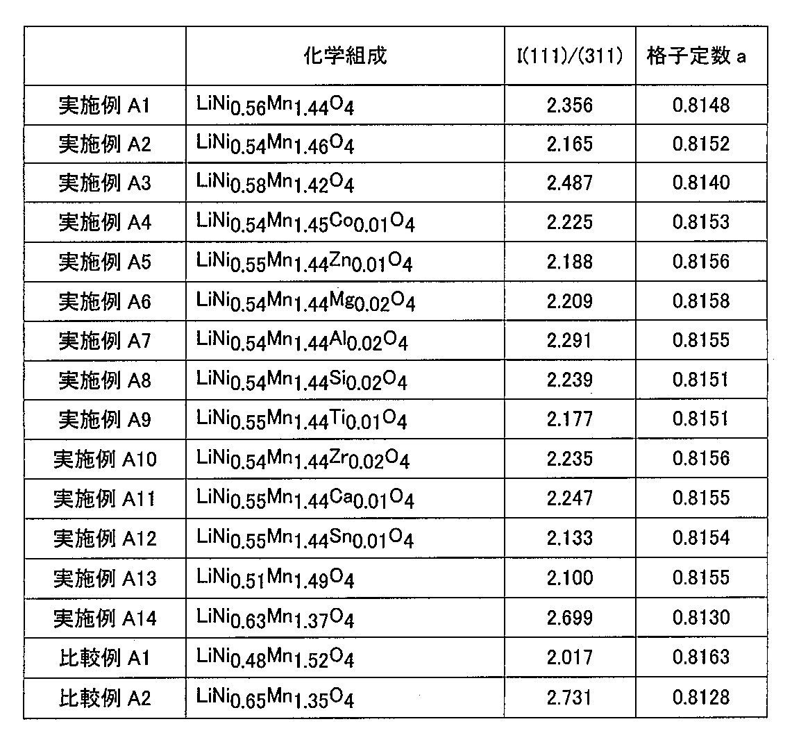
- Table 2 shows the chemical composition, peak intensity ratio, and lattice constant of the obtained lithium composite oxide.
- FIG. 3 shows a powder X-ray diffraction pattern. In FIG. 3, the horizontal axis is 2 ⁇ (°), and the vertical axis is intensity (arbitrary unit).
- a positive electrode slurry was prepared using graphite and acetylene black as the conductive agent and PVdF as the binder.
- the lithium composite oxide powder obtained above, graphite, acetylene black, and PVdF were weighed so that the weight ratio was 85: 5: 5: 5, and then in N-methyl-2-pyrrolidone (NMP).
- NMP N-methyl-2-pyrrolidone
- a simple three-electrode cell was prepared using the positive electrode obtained.
- the positive electrode obtained above was cut into a size of 2 cm ⁇ 2 cm and used.
- a glass nonwoven fabric was used for the separator.
- a Li foil having a size of 2.1 cm ⁇ 2.1 cm was used for the counter electrode.
- a 1 cm ⁇ 0.5 cm Li foil was used as a reference electrode.
- Ni plates were used as current collectors for the counter electrode and the reference electrode.
- the working electrode was opposed to the counter electrode via a separator, and the reference electrode was further placed at a position 1 mm from the working electrode.
- LiPF 6 was dissolved in EC: DMC (1: 2) at a concentration of 1M and used as a non-aqueous electrolyte.
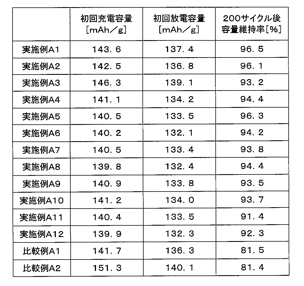
- Examples A2 to A14 A lithium composite oxide was produced in the same manner as in Example A1 except that the conditions of ultrasonic treatment were changed as shown in Table 1 and lithium composite oxides having different chemical compositions were obtained. Using each lithium composite oxide, a three-electrode simple cell was produced and subjected to electrochemical measurement. About each Example, the physical property of lithium complex oxide was shown in Table 2, and the result of the electrochemical measurement in a 3 electrode type simple cell was shown in Table 3.
- Example A1 A lithium composite oxide was prepared in the same manner as in Example A1, except that the ultrasonic treatment was not performed. Using the lithium composite oxide, a three-electrode simple cell was produced and subjected to electrochemical measurement. The physical properties are shown in Table 2, and the results of electrochemical measurements in a three-electrode simple cell are shown in Table 3.
- FIG. 4 shows a powder X-ray diffraction pattern.
- Example A2 A lithium composite oxide was produced in the same manner as in Example A1, except that the ultrasonic treatment conditions were changed as shown in Table 1. Using the lithium composite oxide, a three-electrode simple cell was produced and subjected to electrochemical measurement. The physical properties are shown in Table 2, and the results of electrochemical measurements in a three-electrode simple cell are shown in Table 3.
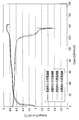
- FIG. 5 shows the charge / discharge curves of Example A1 and Comparative Example A1.
- the charge / discharge curve of Example A1 has a smaller capacity change in the vicinity of 4 to 4.7 V than the charge / discharge curve of Comparative Example A1.
- the vicinity of 4 to 4.7 V is a potential at which a reaction of Mn occurs.
- trivalent Mn becomes tetravalent during charging
- tetravalent Mn becomes trivalent during discharging. From this, it can be seen that Example A1 has less trivalent Mn content than Comparative Example A1.
- Mn that changes from trivalent to tetravalent at the time of charging and then changes again to trivalent at the time of discharging is easily eluted, and thus may be a factor that degrades the cycle performance.
- the content of trivalent Mn can be reduced by using the lithium composite oxide of the first embodiment. Therefore, it is possible to suppress a decrease in cycle performance by using such a lithium composite oxide.
- a non-aqueous electrolyte battery was produced by changing the specific surface area ratio between the positive electrode and the negative electrode, and the capacity retention rate after 500 cycles was measured.
- Example B1 ⁇ Preparation of positive electrode>
- the lithium composite oxide produced in Example A1 was used as the positive electrode active material. Further, graphite and acetylene black were used as the conductive agent, and PVdF was used as the binder. An aluminum foil having a thickness of 15 ⁇ m was used as a current collector.
- a slurry was prepared by dispersing 100 parts by weight of an active material, 3 parts by weight of graphite, 4 parts by weight of acetylene black, and 5 parts by weight of PVdF in a solvent of NMP. This slurry was applied to both sides of an aluminum foil, dried, and press-molded to produce a positive electrode in which an active material-containing layer having a thickness of 28 ⁇ m on one side was formed on both sides of the current collector.
- the specific surface area of this positive electrode measured by mercury porosimetry was 2.5 m 2 / g.
- Li 4 Ti 5 O 12 was used as the negative electrode active material, graphite was used as the conductive agent, and PVdF was used as the binder.
- An aluminum foil having a thickness of 15 ⁇ m was used as a current collector.
- a slurry was prepared by dispersing 100 parts by weight of Li 4 Ti 5 O 12 , 5 parts by weight of graphite, and 5 parts by weight of PVdF in a solvent of NMP. This slurry was applied to both sides of an aluminum foil, dried, and press-molded to produce a negative electrode in which an active material-containing layer having a thickness of 35 ⁇ m on one side was formed on both sides of the current collector.
- the specific surface area of this negative electrode measured by the mercury intrusion method was 8.5 m 2 / g.
- a non-aqueous electrolyte was prepared by mixing 1.5M LiBF 4 in a mixed solvent in which PC and DEC were mixed at a volume ratio of 1: 4.
- a container with a bottomed rectangular tube made of aluminum with a thickness of 0.3 mm and an aluminum lid with a positive electrode terminal inserted and a negative electrode terminal inserted by caulking through an insulating resin are prepared. did.
- the separator was formed of a polyethylene porous film and used by impregnating a non-aqueous electrolyte.
- the positive electrode was covered with a separator, and the negative electrode was stacked so as to face the positive electrode through the separator. This was wound in a spiral shape to produce a spiral electrode group having lead tabs extending from the positive electrode and the negative electrode, respectively. This electrode group was pressed into a flat shape.
- the positive electrode lead tab of the electrode group was connected to one end of the positive electrode terminal of the lid.
- a negative electrode lead tab was connected to one end of the negative electrode terminal.
- the electrode group was inserted into the inside of the container through the opening of the container together with the lid, and the lid was welded to the opening of the container.
- Example B2 As the positive electrode active material, the lithium composite oxide produced in Example A1 was used after being pulverized in a mortar for 2 hours. Otherwise, the battery was fabricated in the same manner as in Example B1. The specific surface area of the positive electrode measured by the mercury intrusion method was 4.25 m 2 / g.
- Example B3 As the negative electrode active material, Li 4 Ti 5 O 12 used in Example B1 was pulverized in a mortar for 6 hours. Otherwise, the battery was fabricated in the same manner as in Example B1. The specific surface area of the negative electrode measured by the mercury intrusion method was 19.8 m 2 / g.
- Comparative Example B The lithium composite oxide produced in Comparative Example A1 was used as the positive electrode active material. Otherwise, the battery was fabricated in the same manner as in Example B1. The specific surface area of the positive electrode measured by the mercury intrusion method was 8.4 m 2 / g.
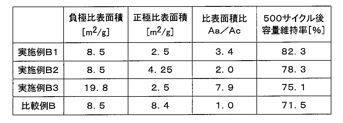
- Example B1 in which the specific surface area ratio (Aa / Ac) between the positive electrode and the negative electrode was 2 or more and less than 8, particularly, had a high capacity retention rate after 500 cycles.
- Example C A nonaqueous electrolyte battery was produced using EC and GBL as the nonaqueous electrolyte, and the capacity retention rate after 500 cycles was measured.
- a mixed solvent in which EC and GBL were mixed at a volume ratio of 1: 2 was mixed with 1.5M LiBF 4 . Otherwise, the battery was fabricated in the same manner as in Example B1.
- Comparative Example C As the non-aqueous electrolyte, a mixed solvent in which EC and GBL were mixed at a volume ratio of 1: 2 was mixed with 1.5M LiBF 4 . Otherwise, a battery was produced in the same manner as in Comparative Example B1.
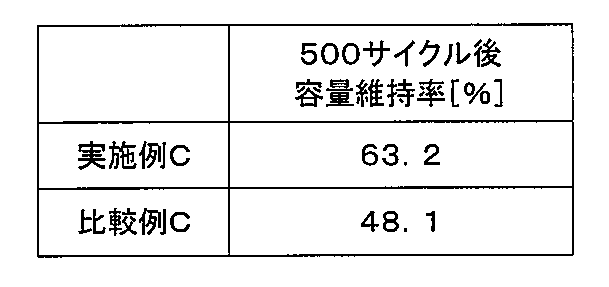
- Example C using the lithium composite oxide of Example A1 as the positive electrode active material was compared with Comparative Example C using the lithium composite oxide of Comparative Example A1 as the positive electrode active material. Even when DEC was not used as the nonaqueous electrolyte, the capacity retention rate after 500 cycles was high.
- Example D A nonaqueous electrolyte battery was prepared using graphite as the negative electrode active material, and the capacity retention rate after 500 cycles was measured.
- Graphite was used as the negative electrode active material, and PVdF was used as the binder.
- An aluminum foil having a thickness of 15 ⁇ m was used as a current collector.
- a slurry was prepared by dispersing 100 parts by weight of graphite and 10 parts by weight of PVdF in an NMP solvent. This slurry was applied to both sides of an aluminum foil, dried, and press-molded to prepare a negative electrode in which an active material-containing layer having a thickness of 30 ⁇ m on one side was formed on both sides of the current collector.
- non-aqueous electrolyte a mixed solvent obtained by mixing EC and DEC at a volume ratio of 1: 4 and 1.5 M LiBF 4 were used.
- a battery was fabricated in the same manner as in Example B1, except that the above negative electrode and nonaqueous electrolyte were used.
- Comparative Example D As the positive electrode active material, the lithium composite oxide produced in Comparative Example A1 was used. Otherwise, the battery was fabricated in the same manner as Example D.
- Example D using the lithium composite oxide of Example A1 as the positive electrode active material was compared with Comparative Example D using the lithium composite oxide of Comparative Example A1 as the positive electrode active material. Even when graphite was used as the negative electrode active material, the capacity retention rate after 500 cycles was high.
- the present invention is not limited to the above-described embodiment as it is, and can be embodied by modifying the constituent elements without departing from the scope of the invention in the implementation stage.
- various inventions can be formed by appropriately combining a plurality of components disclosed in the embodiment. For example, some components may be deleted from all the components shown in the embodiment.
- constituent elements over different embodiments may be appropriately combined.
Landscapes
- Chemical & Material Sciences (AREA)
- Chemical Kinetics & Catalysis (AREA)
- Electrochemistry (AREA)
- General Chemical & Material Sciences (AREA)
- Inorganic Chemistry (AREA)
- Engineering & Computer Science (AREA)
- Materials Engineering (AREA)
- Manufacturing & Machinery (AREA)
- Battery Electrode And Active Subsutance (AREA)
Abstract
スピネル構造を有し、LixNiyMn2-y-zMzO4-b(0.9≦x≦1.15、0.51≦y<0.65、0≦z<0.1、0≦b<0.3、MはCo、Mg、Al、Si、Ti、Zn、Zr、Ti、Ca及びSnから成る群より選択される少なくとも1種の元素を表す)で表され、且つ、下式(I)を満たすリチウム複合酸化物を含むことを特徴とする非水電解質電池用正極活物質;2.1≦I(111)/I(311)<2.7 (I) (但し、I(111)はCuKαを線源とする粉末X線回折法による前記リチウム複合酸化物の(111)面に帰属される最大回折ピーク強度であり、I(311)はCuKαを線源とする粉末X線回折法による前記リチウム複合酸化物の(311)面に帰属される最大回折ピーク強度である)、及び、該正極活物質を含む非水電解質電池(1)を提供する。
Description
本発明は、非水電解質電池、これに用いる正極活物質及びその製造方法に関する。
非水電解質電池をさらに高エネルギー密度化することが求められている。エネルギー密度を高める方法として、電極活物質の単位重量あたりの電気化学当量を小さくすること、負極活物質の作動電位を低くすること、正極活物質の作動電位を高くすることなどがある。
そこで、リチウム電位に対して5Vに近い作動電位を有する正極材料、いわゆる5V系正極材料を用いることによって正極活物質の作動電位を高くし、エネルギー密度を高める方法が検討されている。5V系正極材料としては、例えば化学式LiNi0.5Mn1.5O4で表される材料が知られている(非特許文献1)。しかしながら、このLiNi0.5Mn1.5O4を正極活物質として用いた電池は、実用化するにはサイクル性能が不十分であるという問題がある。
そこで特許文献1では、材料の改良を試みており、化学式LiyNi0.5-xMn1.5+xO4-δ(0.9<y≦1.1、0<x≦0.1、δ>0)を有し、且つ、格子定数が8.167Å~8.190Åであるスピネル構造化合物を開示している(請求項1)。また、特許文献2では、電池設計を検討し、最適化することによって、レート特性、サイクル性能、安全性及び保存性が改善された非水電解質二次電池を提供している(0014段落)。しかしながら、実用化するにはさらなる改良が必要である。
J.Electrochem.Soc,144, p.205, (1997)
本発明は、エネルギー密度が大きく、且つ、優れたサイクル性能を有する非水電解質電池用正極活物質、及びその製造方法を提供することを目的とする。また、該正極活物質を含む正極を用いた非水電解質電池を提供することを目的とする。
本発明の第1態様によると、スピネル構造を有し、LixNiyMn2-y-zMzO4-b(0.9≦x≦1.15、0.51≦y<0.65、0≦z<0.1、0≦b<0.3、MはCo、Mg、Al、Si、Ti、Zn、Zr、Ti、Ca及びSnから成る群より選択される少なくとも1種の元素を表す)で表され、且つ、下記(I)式を満たすリチウム複合酸化物を含むことを特徴とする非水電解質電池用正極活物質が提供される;
2.1≦I(111)/I(311)<2.7 (I)
但し、I(111)はCuKαを線源とする粉末X線回折法による前記リチウム複合酸化物の(111)面に帰属される最大回折ピーク強度であり、I(311)はCuKαを線源とする粉末X線回折法による前記リチウム複合酸化物の(311)面に帰属される最大回折ピーク強度である。
2.1≦I(111)/I(311)<2.7 (I)
但し、I(111)はCuKαを線源とする粉末X線回折法による前記リチウム複合酸化物の(111)面に帰属される最大回折ピーク強度であり、I(311)はCuKαを線源とする粉末X線回折法による前記リチウム複合酸化物の(311)面に帰属される最大回折ピーク強度である。
本発明の第2態様によると、スピネル構造を有し、LixNiyMn2-y-zMzO4-b(0.9≦x≦1.15、0.38≦y<0.45、0≦z<0.1、0≦b<0.3、MはCo、Mg、Al、Si、Ti、Zn、Zr、Ti、Ca及びSnから成る群より選択される少なくとも1種の元素を表す)で表されるリチウム複合酸化物を、Niイオンを含む溶液中に分散する工程と、
前記リチウム複合酸化物が分散された溶液に、出力が50W以上500W以下であり、周波数が10kHz以上1000kHz以下である超音波を照射する工程と、
を含む、非水電解質電池用正極活物質の製造方法が提供される。
前記リチウム複合酸化物が分散された溶液に、出力が50W以上500W以下であり、周波数が10kHz以上1000kHz以下である超音波を照射する工程と、
を含む、非水電解質電池用正極活物質の製造方法が提供される。
本発明の第3態様によると、上記正極活物質を含む正極と、負極と、非水電解質とを含むことを特徴とする非水電解質電池が提供される。
本発明によれば、エネルギー密度が大きく、且つ、優れたサイクル性能を有する非水電解質電池用正極活物質、及びその製造方法が提供される。また、該正極活物質を含む正極を用いた非水電解質電池が提供される。
以下に、本発明の実施形態に係る非水電解質電池用正極活物質、その製造方法、及び、該正極活物質を含む正極を用いた非水電解質電池について図面を参照して説明する。
(第1実施形態)
第1実施形態に係る非水電解質電池用正極活物質は、スピネル構造を有し、LixNiyMn2-y-zMzO4-b(0.9≦x≦1.15、0.51≦y<0.65、0≦z<0.1、0≦b<0.3、MはCo、Mg、Al、Si、Ti、Zn、Zr、Ti、Ca及びSnから成る群より選択される少なくとも1種の元素を表す)で表され、且つ、下記(I)式を満たすリチウム複合酸化物を含む。
2.1≦I(111)/I(311)<2.7 (I)
但し、I(111)はCuKαを線源とする粉末X線回折法による前記リチウム複合酸化物の(111)面に帰属される最大回折ピーク強度であり、I(311)はCuKαを線源とする粉末X線回折法による前記リチウム複合酸化物の(311)面に帰属される最大回折ピーク強度である。
第1実施形態に係る非水電解質電池用正極活物質は、スピネル構造を有し、LixNiyMn2-y-zMzO4-b(0.9≦x≦1.15、0.51≦y<0.65、0≦z<0.1、0≦b<0.3、MはCo、Mg、Al、Si、Ti、Zn、Zr、Ti、Ca及びSnから成る群より選択される少なくとも1種の元素を表す)で表され、且つ、下記(I)式を満たすリチウム複合酸化物を含む。
2.1≦I(111)/I(311)<2.7 (I)
但し、I(111)はCuKαを線源とする粉末X線回折法による前記リチウム複合酸化物の(111)面に帰属される最大回折ピーク強度であり、I(311)はCuKαを線源とする粉末X線回折法による前記リチウム複合酸化物の(311)面に帰属される最大回折ピーク強度である。
なお、リチウム複合酸化物の化学組成は、ICP発光分光分析により求めたものである。また、粉末X線回折パターンにおいて、リチウム複合酸化物の(111)面に帰属される回折ピークは、2θ=19°付近に現れる最大ピークであり、リチウム複合酸化物の(311)面に帰属される回折ピークは、2θ=36°付近に現れる最大ピークである。ここで、2θ=19°付近とは、2θ=19°±2°の範囲を意味するように意図される。
LiNi0.5Mn1.5O4を正極活物質として用いた場合に、電池のサイクル性能が不十分である原因として、正極活物質からMnが溶出すること、及び、作動電位が高いために電極と非水電解質が反応し、電極抵抗が上昇することが考えられる。
本発明者らが鋭意検討を行った結果、スピネル構造のリチウム複合酸化物の化学組成と結晶性を適切な範囲とすることにより、サイクル性能を向上できることが見出された。
化学組成がLixNiyMn2-y-zMzO4-b(0.9≦x≦1.15、0.51≦y<0.65、0≦z<0.1、0≦b<0.3、MはCo、Mg、Al、Si、Ti、Zn、Zr、Ti、Ca及びSnから成る群より選択される少なくとも1種の元素を表す)であるスピネル構造のリチウム複合酸化物は、Mnの一部がNiに置換されたものである。リチウム複合酸化物中において、Niは2価であり、Mnは3価又は4価である。リチウム複合酸化物中のMnの一部をNiに置換すると、リチウム複合酸化物中で3価のMnの一部が4価のMnに変化すると考えられる。4価のMnは3価のMnと比較して非水電解質中に溶出し難いため、前記化学組成を有するスピネル構造のリチウム複合酸化物においては、Mnの溶出が抑制されたと考えられる。
このリチウム複合酸化物のピーク強度I(111)/I(311)を2.1以上2.7未満にすることにより、リチウム複合酸化物の結晶性が高くなるため、リチウムイオンの挿入及び脱離が円滑に行われる。それ故、電極と非水電解質との反応が抑制される。これらの結果、サイクル性能が向上されると考えられる。
なお、前記化学組成を有するスピネル構造のリチウム複合酸化物であっても、ピーク強度I(111)/I(311)が2.1未満であると、リチウム複合酸化物の結晶性が低いため、非水電解質との反応性が高くなり、サイクル性能が低下する。一方、ピーク強度I(111)/I(311)が2.7以上であると、リチウム複合酸化物の結晶構造が変化するため、サイクル性能が低下する。
以上のように、5V系正極材料であるリチウム複合酸化物を用い、且つ、このリチウム複合酸化物の化学組成とピーク強度比を上記範囲内にすることにより、エネルギー密度が高く、且つサイクル性能に優れた正極活物質を提供することが可能である。
上記のようなリチウム複合酸化物は、さらに、格子定数aの値が0.813以上0.8159以下の範囲内であることが好ましい。格子定数aは原子間の距離を表す。Ni原子はMn原子より小さいため、MnがNiにより置換された場合、格子定数aは小さくなる。ICP発光分光分析により化学組成を求めた場合、Niが粒子表面に付着している場合も含まれるが、格子定数aの値が0.8159以下であることにより、MnがNiにより置換されていることが分かる。一方、格子定数aの値が0.813以上であると、リチウム複合酸化物の結晶構造が変化せず、サイクル性能が良好である。
(第2実施形態)
本発明の第2実施形態として、上記第1実施形態に係る非水電解質電池用正極活物質に用いられるリチウム複合酸化物の製造方法を以下に詳細に説明する。
本実施形態においては、スピネル構造を有し、LixNiyMn2-y-zMzO4-b(0.9≦x≦1.15、0.38≦y<0.45、0≦z<0.1、0≦b<0.3、MはCo、Mg、Al、Si、Ti、Zn、Zr、Ti、Ca及びSnから成る群より選択される少なくとも1種の元素を表す)で表されるリチウム複合酸化物(これ以後、「原料リチウム複合酸化物」と称する)を、Niイオンを含む溶液中に分散させ、超音波処理を行なう。
本発明の第2実施形態として、上記第1実施形態に係る非水電解質電池用正極活物質に用いられるリチウム複合酸化物の製造方法を以下に詳細に説明する。
本実施形態においては、スピネル構造を有し、LixNiyMn2-y-zMzO4-b(0.9≦x≦1.15、0.38≦y<0.45、0≦z<0.1、0≦b<0.3、MはCo、Mg、Al、Si、Ti、Zn、Zr、Ti、Ca及びSnから成る群より選択される少なくとも1種の元素を表す)で表されるリチウム複合酸化物(これ以後、「原料リチウム複合酸化物」と称する)を、Niイオンを含む溶液中に分散させ、超音波処理を行なう。
原料リチウム複合酸化物は、周知の方法によって作製されたものであってよい。或いは、超音波処理に先立って任意の方法により作製してもよい。固相法によればスピネル構造を有し所望の化学組成を有する原料リチウム複合酸化物を有利に作製することができる。
固相法においては、リチウム源、マンガン源、及びニッケル源となる化合物を所定の比率で混合し、加熱することによって、原料リチウム複合酸化物を作製する。
例えば、LiMn1.52Ni0.48O4組成となるように秤量したLi2CO3、MnO2、及び、Ni(OH)2を湿式混合し、仮焼(例えば、600℃、酸素フロー、24時間)し、得られた粉末を本焼(例えば、700℃、酸素フロー、24時間)する。このようにして得られた原料リチウム複合酸化物の粉末は、例えば、ICP発光分析により求めた化学組成が、LiMn1.52Ni0.48O4であり、粉末X線回折法により求めたピーク強度I(111)/I(311)が1.69であった。
原料リチウム複合酸化物を、Niイオンを含む溶液中に分散させる。Niイオンを含む溶液は、任意のものであってよいが、弱酸性の溶液であることが好ましい。溶液中のNiイオン濃度は、0.1~20重量パーセントの範囲であることが好ましい。
Niイオン源は、Niを含む無機酸又は有機酸を用いることができるがこれらに限定されない。例えば、酢酸ニッケル(II)四水和物を用いることができる。溶媒は、ニッケルがイオン化するものであれば何れのものであってもよく、例えば精製水を用いることができる。
次いで、原料リチウム複合酸化物が分散した溶液を超音波処理する。例えば、原料リチウム複合酸化物の粉末を分散させた溶液を容器中に入れ、該容器に超音波を照射する。
超音波処理により、原料リチウム複合酸化物を改質することができる。改質が進むと、粉末X線回折法におけるメインピークI(111)の強度が増大し、これによってピーク強度比I(111)/I(311)が増大する。よって、適切に超音波処理を行うことにより、所望のピーク強度比を有するリチウム複合酸化物を得ることができる。
また、Niイオンを含む溶液中で原料リチウム複合酸化物を超音波処理することにより、リチウム複合酸化物のMnの一部をNiに置換することができる。よって、適切に超音波処理を行うことにより、所望の化学組成を有するスピネル構造のリチウム複合酸化物を得ることができる。一方、超音波処理での改質が進みすぎた場合、結晶構造の変化や粉末表面物性の変化によりサイクル特性に悪影響を及ぼす可能性がある。
超音波処理条件は、出力が50W以上500W以下であり、周波数が10kHz以上1000kHz以下であり、照射時間は特に限定されるものではないが5分間以上10時間以下である。
出力が50W未満であると超音波処理による十分な材料改質効果が得られない可能性がある。一方、出力が500Wを越えると超音波処理による粒子へのダメージが大きく悪影響を及ぼす可能性がある。周波数が10kHz未満であると超音波により発生する泡の数が不十分で均一な改質が行えないおそれがある。上限は特に限定されないが、実用性の観点から、1000kHz程度が好ましい。照射時間は、5分未満であると均質な材料改質が行われず十分な効果が得られない可能性がある。一方、10時間より長いと超音波処理による粒子へのダメージが大きく悪影響を及ぼす可能性がある。
なお、MnがNiにより置換されるにつれて、格子定数aの値は低下する。上記したように、格子定数aの値は0.813以上0.8159以下の範囲内であることが好ましい。格子定数aの値が0.813以上0.8159以下の範囲内であることにより、リチウム複合酸化物が適度に改質され、且つMnの一部がNiにより置換されていることが分かる。
超音波処理が終了した後、リチウム複合酸化物が分散された溶液をろ過し、乾燥することにより、所望の化学組成及びピーク強度比を有するスピネル構造のリチウム複合酸化物を得ることができる。
次に、粉末X線回折法による回折パターンの測定方法について説明する。対象となるリチウム複合酸化物を深さ0.2mmのガラス試料板に試料を詰めて、外部からガラス板を使い、充分に押し付けて平滑化した状態にして測定を行う。このとき、測定試料が十分にホルダー部分に充填されるように留意し、例えばひび割れや空隙といった試料の充填不足等がないように注意する。また、試料をガラスホルダーの深さ(0.2mm)と同一となるように充填し、充填量の過不足により、ガラスホルダーの基準面より凹凸が生じることのないように注意する。また、試料をCu-Kα線による粉末X線回折測定する際、粉体として測定する以外に、後述の導電剤ならびに結着剤を含む電極を測定することが可能である。例えば、リチウム複合酸化物の粉末と結着剤と導電剤とを汎用されている溶媒に懸濁することにより作製したスラリーを、電極集電体に塗布し、乾燥し、電極層を作製した後、プレスを施すことにより電極を作製する。このように作製された電極をX線回折測定に供しても同様の回折パターンを測定することができる。また、非水電解質電池を解体し電極を取り出し、例えばメチルエチルカーボネートで洗浄した後に乾燥したものをX線回折測定に供しても同様の回折パターンを測定することができる。
Cu-Kα線源を持つ粉末X線回折装置の測定条件は、走査速度3 deg/min、ステップ幅0.2 deg、管電圧40 kV、管電流20 mAを標準として測定を行ったが、必要に応じて十分なピーク強度が得られる条件へ変更することが望ましい。
格子定数aは、市販のソフトウェア(例えばRigaku社製JADE)を用いて得られたピーク位置情報から、格子面間隔を算出して格子定数の初期値を算出した。得られた初期値を用いて、リートベルト法により格子定数の精密化を行った。
(第3実施形態)
本発明の第3実施形態として、第1実施形態に係るリチウム複合酸化物を含む正極を用いた非水電解質電池について以下に説明する。
本発明の第3実施形態として、第1実施形態に係るリチウム複合酸化物を含む正極を用いた非水電解質電池について以下に説明する。
第3実施形態に係る非水電解質電池は、上記第1実施形態に係る非水電解質電池用正極活物質を含む正極、負極、非水電解質、セパレータ及び外装材を含む。
本実施形態における非水電解質電池では、正極の比表面積Ac[m2/g]と、負極の比表面積Aa[m2/g]は、下式(II)を満たすことが好ましい。
2≦Aa/Ac<8 (II)
なお、ここで各極の比表面積は、水銀圧入法により測定されるものである。
2≦Aa/Ac<8 (II)
なお、ここで各極の比表面積は、水銀圧入法により測定されるものである。
正極の比表面積Ac[m2/g]と、負極の比表面積Aa[m2/g]が式(II)を満たすことにより、サイクル性能を向上させることができる。
電極の比表面積を大きくすると目的である電池反応が促進される一方で副反応も促進される。そのため、正極においては金属成分の溶出を抑制するために比表面積を比較的小さくすることが好ましい。一方、負極においては電池反応を促進させるために比表面積を比較的大きくすることが好ましい。前述のLiに対して1V以上で作動する負極においては還元反応が起こりにくいので比表面積を大きくすることでの電池性能向上の効果はより得られやすい。
Aa/Acの値を2以上とすることにより、正極からの金属溶出を抑制し、電池抵抗の増加によるサイクル性能の劣化を防ぐことができる。一方、Aa/Acの値を8未満とすることにより、負極での副反応を抑制し、電池抵抗の増加によるサイクル性能の劣化を防ぐことができる。
以下、正極、負極、非水電解質、セパレータ、外装材について詳細に説明する。
1)正極
正極は、集電体と、この集電体の片面もしくは両面に形成され、活物質、導電剤及び結着剤を含む正極層(正極活物質含有層)とを含む。
正極は、集電体と、この集電体の片面もしくは両面に形成され、活物質、導電剤及び結着剤を含む正極層(正極活物質含有層)とを含む。
活物質は、第1実施形態で説明したリチウム複合酸化物を含む電池用活物質である。該リチウム複合酸化物は、スピネル構造を有し、LixNiyMn2-y-zMzO4-b(0.9≦x≦1.15、0.51≦y<0.65、0≦z<0.1、0≦b<0.3、MはCo、Mg、Al、Si、Ti、Zn、Zr、Ti、Ca及びSnから成る群より選択される少なくとも1種の元素を表す)で表され、且つ、下記(I)式を満たすリチウム複合酸化物である。
2.1≦I(111)/I(311)<2.7 (I)
但し、I(111)はCuKαを線源とする粉末X線回折法による前記リチウム複合酸化物の(111)面に帰属される最大回折ピーク強度であり、I(311)はCuKαを線源とする粉末X線回折法による前記リチウム複合酸化物の(311)面に帰属される最大回折ピーク強度である。また、該リチウム複合酸化物は、格子定数aの値が0.813以上0.8159以下の範囲内であることが好ましい。
2.1≦I(111)/I(311)<2.7 (I)
但し、I(111)はCuKαを線源とする粉末X線回折法による前記リチウム複合酸化物の(111)面に帰属される最大回折ピーク強度であり、I(311)はCuKαを線源とする粉末X線回折法による前記リチウム複合酸化物の(311)面に帰属される最大回折ピーク強度である。また、該リチウム複合酸化物は、格子定数aの値が0.813以上0.8159以下の範囲内であることが好ましい。
このようなリチウム複合酸化物を含む活物質を用いた正極は、非水電解質電池のエネルギー密度を向上し、且つサイクル性能を向上することができる。
活物質として、第1実施形態に係る活物質を単独で用いてもよいが、他の活物質と混合して用いてもよい。ただし、全活物質重量のうち40重量%以上は前記スピネル構造活物質とすることが好ましい。これにより、エネルギー密度増加の効果を十分に得ることができる。前記スピネル構造活物質のより好ましい含有量は全活物質重量に対して60~100重量%である。
他の活物質としては、例えば、二酸化マンガン(MnO2)、酸化鉄、酸化銅、酸化ニッケル、LiaMnO2、リチウムコバルト複合酸化物(LiaCoO2)、リチウムマンガンコバルト複合酸化物(例えば、LiMn1-g-hCogMhO2、ここでMはAl,Cr,Mg及びFeよりなる群から選択される少なくとも1つまたは2つ以上の元素、0≦g≦0.5、0≦h≦0.1)、リチウムマンガンニッケル複合酸化物(例えば、LiMnjNijM1-2jO2、ここでMはCo,Cr,Al,Mg及びFeよりなる群より選択される少なくとも1つまたは2つ以上の元素、1/3≦j≦1/2、LiMn1/3Ni1/3Co1/3O2、LiMn1/2Ni1/2O2)、スピネル型リチウムマンガン複合酸化物(例えば、LiaMn2-bMbO4、ここでMはAl,Cr,Ni及びFeよりなる群から選択される少なくとも1つまたは2つ以上の元素)、オリビン構造を有するリチウムリン酸化物(例えばLiaFePO4、LiaFe1-bMnbPO4、LiaCoPO4など)、硫酸鉄(Fe2(SO4)3)、バナジウム酸化物(例えばV2O5)を用いることができる。なお、上記においてa及びbは、それぞれ0~1.1であることが好ましい。
また、活物質として、ポリアニリンやポリピロールなどの導電性ポリマー材料、ジスルフィド系ポリマー材料、イオウ(S)、フッ化カーボンなどの有機材料及び無機材料を用いることもできる。
より好ましい正極活物質は、リチウムコバルト複合酸化物、リチウムマンガンニッケル複合酸化物、スピネル型リチウムマンガン複合酸化物、リチウムマンガンコバルト複合酸化物、リチウムリン酸鉄を用いることができる。
導電剤は、集電性能を高め、且つ活物質と集電体との接触抵抗を抑えるために必要に応じて配合される。導電剤の例には、アセチレンブラック、カーボンブラック、黒鉛のような炭素質物が含まれる。
結着剤は、活物質と集電体を結着させる。結着剤の例には、ポリテトラフルオロエチレン(PTFE)、ポリフッ化ビニリデン(PVdF)、フッ素系ゴムが含まれる。
正極層において、活物質、導電剤及び結着剤はそれぞれ73~95重量%、3~20重量%、2~7重量%の割合で配合することが好ましい。
導電剤は、3重量%以上の量にすることにより上述した効果を発揮することができる。また、20重量%以下にすることにより、高温保存下での正極導電剤表面での非水電解質の分解を低減することができる。
結着剤は、2重量%以上の量にすることにより十分な電極強度が得られる。また、7重量%以下にすることにより電極の絶縁体の配合量を減少させ、内部抵抗を減少できる。
集電体は、アルミニウム箔、又は、Mg、Ti、Zn、Ni、Cr、Mn、Fe、Cu、Siのような元素を含むアルミニウム合金箔であることが好ましい。
集電体を構成するアルミニウム箔またはアルミニウム合金箔は、50μm以下、より好ましくは30μm以下、更に好ましくは5μm以下の平均結晶粒径を有することが望ましい。アルミニウム箔またはアルミニウム合金箔の平均結晶粒径を50μm以下にすることによって、アルミニウム箔またはアルミニウム合金箔の強度を飛躍的に増大させることができる。このため、プレス時の圧力を高めて正極活物質含有層を高密度化して正極容量を増大させることが可能になる。
平均結晶粒径は、次のように方法で求めることができる。集電体表面の組織を光学顕微鏡で観察し、1mm×1mm内に存在する結晶粒の数(n)を求める。このnを用いてS=1×10⁶/n(μm2)から平均結晶粒子面積Sを求める。得られたSの値から下式(A)により平均結晶粒子径d(μm)を算出する。
d=2(S/π)1/2 …(A)
アルミニウム箔またはアルミニウム合金箔の平均結晶粒径は、材料組織、不純物、加工条件、熱処理履歴、ならびに焼鈍条件など複数の因子から複雑な影響を受けて変化する。結晶粒径は、集電体の製造工程の中で、前記諸因子を組合せて調整することが可能である。
アルミニウム箔またはアルミニウム合金箔の平均結晶粒径は、材料組織、不純物、加工条件、熱処理履歴、ならびに焼鈍条件など複数の因子から複雑な影響を受けて変化する。結晶粒径は、集電体の製造工程の中で、前記諸因子を組合せて調整することが可能である。
アルミニウム箔またはアルミニウム合金箔の厚さは、20μm以下、より好ましくは15μm以下であることが望ましい。アルミニウム箔は99重量%以上の純度を有することが好ましい。アルミニウム箔またはアルミニウム合金箔に含まれる鉄、銅、ニッケル、クロムなどの遷移金属の含有量は、1重量%以下にすることが好ましい。
アルミニウム箔またはアルミニウム合金箔は、前述したように表面が粗面化されることが好ましい。
正極は、例えば、活物質、導電剤及び結着剤を適当な溶媒に懸濁してスラリーを調製し、このスラリーを正極集電体に塗布し、乾燥して正極層を形成した後、プレスを施すことにより作製される。正極はまた、活物質、導電剤及び結着剤をペレット状に形成して正極層とし、これを集電体上に形成することにより作製されてもよい。
2)負極
負極は、集電体と、該集電体の片面若しくは両面に形成され、活物質、導電剤及び結着剤を含む負極層(負極活物質含有層)とを含む。
負極は、集電体と、該集電体の片面若しくは両面に形成され、活物質、導電剤及び結着剤を含む負極層(負極活物質含有層)とを含む。
活物質には、例えば、リチウムチタン複合酸化物、炭素質物、又は金属化合物を用いることができる。
リチウムチタン複合酸化物としては、例えばLi4+xTi5O12(-1≦x≦3)で表されるスピネル型のチタン酸リチウム、又は、Li2+xTi3O7(-1≦x≦3)で表されるラムステライド型のチタン酸リチウム、TiとP、V、Sn、Cu、Ni及びFeから成る群から選択される少なくとも1種の元素を含有する金属複合酸化物を用いることができる。
該金属複合酸化物は、例えば、TiO2-P2O5、TiO2-V2O5、TiO2-P2O5-SnO2、TiO2-P2O5-MeO(MeはCu、Ni及びFeから成る群より選択される少なくとも1種の元素)であってよい。
この金属複合酸化物は、結晶性が低いミクロ構造を有することが好ましい。例えば、結晶相とアモルファス相が共存しているか、又はアモルファス相が単独で存在していることが好ましい。このようなミクロ構造を有する金属複合酸化物は、サイクル性能を大幅に向上させることができる。これらの金属複合酸化物は、充電によりリチウムが挿入されることでリチウムチタン複合酸化物になる。なかでもスピネル型チタン酸リチウムがサイクル性能に優れているため好ましい。
炭素質物としては、例えば天然黒鉛、人造黒鉛、コークス、気相成長炭素繊維、メソフェーズピッチ系炭素繊維、球状炭素、又は樹脂焼成炭素を用いることができる。特に、気相成長炭素繊維、メソフェーズピッチ系炭素繊維、球状炭素を用いることが好ましい。炭素質物は、粉末X線回折法による(002)面の面間隔d002が0.34nm以下であることが好ましい。
金属化合物としては、金属硫化物又は金属窒化物を用いることができる。金属硫化物は、例えば、TiS2のような硫化チタン、MoS2のような硫化モリブデン、FeS、FeS2、LixFeS2のような硫化鉄であってよい。金属窒化物は、例えば、リチウムコバルト窒化物(例えばLisCotN、0<s<4,0<t<0.5)であってよい。
以上の活物質は、単独で用いてもよいが、二種以上の活物質を混合して用いてもよい。
第1実施形態のリチウム複合酸化物を含む正極を用いた非水電解質電池は、高電圧作動が可能となる。しかしながら、正極作動電位が高い程、正極活物質からの遷移金属の溶出が多くなる傾向がある。正極から溶出した遷移金属は、負極に析出し、負極抵抗を増加させてサイクル性能を劣化させる原因となる。そこで、負極活物質は、Liに対して1V以上の電位でリチウムイオンを吸蔵・放出可能であることが好ましい。Liに対して1V以上の電位でリチウムイオンを吸蔵・放出可能である負極活物質を用いることによって、正極から溶出した遷移金属が負極に析出するのを抑制することができる。Liに対して1V以上の電位でリチウムイオンを吸蔵・放出可能である負極活物質としては、上記のリチウムチタン複合酸化物、金属複合酸化物、金属硫化物を用いることができ、特に、Li4+xTi5O12(-1≦x≦3)のようなスピネル構造のチタン酸リチウムが好ましい。
導電剤は、活物質の集電性能を高め、集電体との接触抵抗を抑える。導電剤の例には、アセチレンブラック、カーボンブラック、黒鉛等の炭素質物が含まれる。
結着剤は、分散された負極活物質の間隙を埋めるために配合され、活物質と導電剤を結着する。結着剤の例には、ポリテトラフルオロエチレン(PTFE)、ポリフッ化ビニリデン(PVdF)、フッ素系ゴム、スチレンブタジェンゴムが含まれる。
負極層中の活物質、導電剤及び結着剤は、それぞれ、73重量%以上96重量%以下、2重量%以上20重量%以下、及び、2重量%以上7重量%以下の範囲で配合されていることが好ましい。導電剤の量が2重量%以上であると、負極層の集電性能が良好である。また、結着剤の量が2重量%以上であると、負極層と集電体の結着性が十分で、優れたサイクル性能を期待できる。
集電体は、アルミニウム箔、又は、Mg、Ti、Zn、Ni、Cr、Mn、Fe、Cu、Siのような元素を含むアルミニウム合金箔であることが好ましい。
集電体を構成するアルミニウム箔またはアルミニウム合金箔は、50μm以下、より好ましくは30μm以下、更に好ましくは5μm以下の平均結晶粒径を有することが望ましい。平均結晶粒径は、前述した方法で求めることができる。アルミニウム箔またはアルミニウム合金箔の平均結晶粒径を50μm以下にすることによって、アルミニウム箔またはアルミニウム合金箔の強度を飛躍的に増大させることができる。このため、プレス時の圧力を高めて負極活物質含有層を高密度化して負極容量を増大させることが可能になる。また、高温環境下(40℃以上)における過放電サイクルでの集電体の溶解・腐食劣化を防ぐことができる。このため、負極インピーダンスの上昇を抑制することができる。さらに、出力特性、急速充電、充放電サイクル性能も向上させることができる。
アルミニウム箔またはアルミニウム合金箔の平均結晶粒径は、材料組織、不純物、加工条件、熱処理履歴、ならびに焼鈍条件など複数の因子から複雑な影響を受けて変化する。結晶粒径は、集電体の製造工程の中で、前記諸因子を組合せて調整することが可能である。
アルミニウム箔またはアルミニウム合金箔の厚さは、20μm以下、より好ましくは1.50μm以下であることが望ましい。アルミニウム箔は99重量%以上の純度を有することが好ましい。アルミニウム合金は、マグネシウム、亜鉛、ケイ素などの元素を含む合金であることが好ましい。合金成分として含まれる鉄、銅、ニッケル、クロムなどの遷移金属は1重量%以下にすることが好ましい。
負極は、例えば粉末状の活物質と、導電剤及び結着剤を、汎用されている溶媒に懸濁してスラリーを調製し、このスラリーを集電体に塗布し、乾燥し、負極層を形成した後、プレスを施すことにより作製される。負極はまた、活物質、導電剤及び結着剤をペレット状に形成して負極層とし、これを集電体上に形成することにより作製されてもよい。
3)非水電解質
非水電解質は、例えば、電解質を有機溶媒に溶解することにより調製される液状非水電解質、又は、液状電解質と高分子材料を複合化したゲル状非水電解質であってよい。
非水電解質は、例えば、電解質を有機溶媒に溶解することにより調製される液状非水電解質、又は、液状電解質と高分子材料を複合化したゲル状非水電解質であってよい。
電解質の例には、LiPF6、LiBF4、Li(CF3SO2)2N(ビストリフルオロメタンスルホニルアミドリチウム;通称LiTFSI)、LiCF3SO3(通称LiTFS)、Li(C2F5SO2)2N(ビスペンタフルオロエタンスルホニルアミドリチウム;通称LiBETI)、LiClO4、LiAsF6、LiSbF6、ビスオキサラトホウ酸リチウム(LiB(C2O4)2(通称LiBOB))、ジフルオロ(トリフルオロ-2-オキシド-2-トリフルオロ-メチルプロピオナト(2-)-0,0)ホウ酸リチウム(LiBF2(OCOOC(CF3)2)(通称LiBF2(HHIB)))のようなリチウム塩、またはこれらの混合物が含まれる。特にLiPF6、LiBF4が好ましい。
電解質塩濃度は、0.5~3モル/Lにすることが好ましい。電解質塩濃度がこのような範囲内であることにより、電解質塩濃度の上昇による粘度増加の影響を抑えつつ、高負荷電流を流した場合の性能をより向上することが可能になる。
有機溶媒の例には、これらに限定されないが、プロピレンカーボネート(PC)、エチレンカーボネート(EC)、1,2-ジメトキシエタン(DME)、γ-ブチロラクトン(GBL)、テトラヒドロフラン(THF)、2-メチルテトラヒドロフラン(2-MeHF)、1,3-ジオキソラン、スルホラン、アセトニトリル(AN)、ジエチルカーボネート(DEC)、ジメチルカーボネイト(DMC)、メチルエチルカーボネート(MEC)、ジプロピルカーボネート(DPC)が含まれる。これらの有機溶媒は、単独又は混合溶媒の形態で用いることができる。特に、耐酸化性が高いため、ジエチルカーボネートを用いることが好ましい。ジエチルカーボネートは、非水電解質の全重量に対して50~90重量%の割合で含有されることが好ましい。
高分子材料の例には、ポリフッ化ビニリデン(PVdF)、ポリアクリロニトリル(PAN)、ポリエチレンオキサイド(PEO)が含まれる。
非水電解質には、添加剤が加えられてもよい。添加剤は、特に限定されるものではないが、例えばビニレンカーボネイト(VC)、ビニレンアセテート(VA)、ビニレンブチレート、ビニレンヘキサネート、ビニレンクロトネート、カテコールカーボネートを用いることができる。添加剤の配合量は、非水電解質に対して外率で0.1~3重量%であることが好ましく、0.5~1重量%であることがさらに好ましい。
4)セパレータ
セパレータは、例えば、ポリエチレン、ポリプロピレン、セルロース、またはポリフッ化ビニリデン(PVdF)を含む多孔質フィルム、合成樹脂製不織布から形成されてよい。中でも、ポリエチレン又はポリプロピレンから形成された多孔質フィルムは、一定温度において溶融し、電流を遮断することが可能であるため、安全性を向上できる。
セパレータは、例えば、ポリエチレン、ポリプロピレン、セルロース、またはポリフッ化ビニリデン(PVdF)を含む多孔質フィルム、合成樹脂製不織布から形成されてよい。中でも、ポリエチレン又はポリプロピレンから形成された多孔質フィルムは、一定温度において溶融し、電流を遮断することが可能であるため、安全性を向上できる。
5)外装材
外装材は、厚さ0.5mm以下のラミネートフィルムまたは厚さ1mm以下の金属製容器が用いることができる。ラミネートフィルムの厚さは0.2mm以下であることがより好ましい。金属製容器は、厚さ0.5mm以下であることがより好ましく、厚さ0.2mm以下であることがさらに好ましい。
外装材は、厚さ0.5mm以下のラミネートフィルムまたは厚さ1mm以下の金属製容器が用いることができる。ラミネートフィルムの厚さは0.2mm以下であることがより好ましい。金属製容器は、厚さ0.5mm以下であることがより好ましく、厚さ0.2mm以下であることがさらに好ましい。
外装材の形状は、扁平型(薄型)、角型、円筒型、コイン型、ボタン型等が挙げられる。外装材は、電池寸法に応じて、例えば携帯用電子機器等に積載される小型電池用外装材、二輪乃至四輪の自動車等に積載される大型電池用外装材が挙げられる。
ラミネートフィルムは、樹脂層間に金属層を介在した多層フィルムが用いられる。金属層は、軽量化のためにアルミニウム箔もしくはアルミニウム合金箔が好ましい。樹脂層は、例えばポリプロピレン(PP)、ポリエチレン(PE)、ナイロン、ポリエチレンテレフタレート(PET)等の高分子材料を用いることができる。ラミネートフィルムは、熱融着によりシールを行って外装材の形状に成形することができる。
金属製容器は、アルミニウムまたはアルミニウム合金等から作られる。アルミニウム合金は、マグネシウム、亜鉛、ケイ素等の元素を含む合金が好ましい。合金中に鉄、銅、ニッケル、クロム等の遷移金属を含む場合、その含有量は1重量%以下にすることが好ましい。これにより、高温環境下での長期信頼性、放熱性を飛躍的に向上させることができる。
次に、第3実施形態に係る非水電解質電池を、図面を参照してより具体的に説明する。図1は、第3実施形態に係る非水電解質電池の一例である、扁平型非水電解質電池の部分切欠斜視図である。図2は図1のA部の拡大断面図である。なお、各図は発明の説明とその理解を促すための模式図であり、その形状や寸法、比などは実際の装置と異なる点があるが、これらは以下の説明と公知の技術を参酌して適宜設計変更することができる。
図1に示す扁平型非水電解質電池1において、捲回電極群13は、金属製の有底矩形筒状外装材11内に収納されている。
扁平状の捲回電極群13は、図2に示すように、外側から負極3、セパレータ4、正極5、セパレータ4の順で積層した積層物を渦巻状に捲回し、プレス成型することにより形成される。負極3は、負極集電体3aとその片面又は両面に形成された負極活物質層3bを含む。正極5は、正極集電体5aとその片面又は両面に形成された正極活物質層5bを含む。
負極タブ18は、その一端が負極集電体3aに接続され、他端が矩形蓋体12に負極ガスケット21を介して固定された負極端子20に接続されている。正極タブ17は、その一端が正極集電体5aに接続され、他端が矩形蓋体12に固定された正極端子19に接続されている。
非水電解質は、例えば矩形状外装材11の開口部から注入されて、矩形状外装材11内に収容されている。矩形状外装材11の開口部に矩形蓋体12を溶接することにより、捲回電極群13及び非水電解質が矩形状外装材11内に封止されている。
負極タブは、例えば、アルミニウム又はMg、Ti、Zn、Mn、Fe、Cu、Si等の元素を含むアルミニウム合金などの材料で製造される。負極タブは、負極集電体との接触抵抗を低減するために、負極集電体と同様の材料であることが好ましい。
正極タブは、例えば、アルミニウム又はMg、Ti、Zn、Mn、Fe、Cu、Si等の元素を含むアルミニウム合金などの材料で製造される。正極タブは、正極集電体との接触抵抗を低減するために、正極集電体と同様の材料であることが好ましい。
以上説明した実施形態に係る非水電解質二次電池は、上記第1実施形態に係る正極活物質を含む正極を用いたことにより、エネルギー密度が大きく、且つ、充放電サイクルにおける劣化が小さく、優れたサイクル性能を有するものである。
以下、本発明の実施例を詳細に説明する。
(実施例A1)
Li2CO3、MnO2、及び、Ni(OH)2を、LiNi0.5Mn1.5O4の組成となる比で湿式混合し、600℃、酸素フロー、24時間の条件で仮焼した。得られた粉末を、700℃、酸素フロー、24時間の条件で本焼し、原料リチウム複合酸化物の粉末を得た。
Li2CO3、MnO2、及び、Ni(OH)2を、LiNi0.5Mn1.5O4の組成となる比で湿式混合し、600℃、酸素フロー、24時間の条件で仮焼した。得られた粉末を、700℃、酸素フロー、24時間の条件で本焼し、原料リチウム複合酸化物の粉末を得た。
得られた原料リチウム複合酸化物のICP発光分析により求められた化学組成は、LiNi0.48Mn1.52O4であり、粉末X線回折パターンからスピネル構造であることを確認した。また粉末X線回折パターンにおけるピーク強度比I(111)/I(311)は1.690であり、格子定数aは0.8163あった。
酢酸ニッケル(II)四水和物と二次蒸留水を重量比1:99で混合し、1wt%-酢酸ニッケル溶液を調製した。この溶液10mlに、上記で得られた原料リチウム複合酸化物の粉末1gを添加して分散させた。この混合溶液を、周波数28kHz、出力300W、40分間の条件で超音波処理した。原料リチウム複合酸化物の化学組成と超音波処理の条件を表1に示した。超音波処理後、混合溶液を濾過し、残渣を大気雰囲気下、600℃で2時間乾燥し、目的のリチウム複合酸化物を得た。
得られたリチウム複合酸化物のICP発光分析により求められた化学組成は、LiNi0.56Mn1.44O4であり、粉末X線回折パターンからスピネル構造であることを確認した。また粉末X線回折パターンにおけるピーク強度比I(111)/I(311)は2.273であり、格子定数aは0.8148あった。得られたリチウム複合酸化物の化学組成、ピーク強度比、及び格子定数を表2に示した。図3に、粉末X線回折パターンを示した。図3において、横軸は2θ(°)であり、縦軸は強度(任意単位)である。
導電剤としてグラファイト及びアセチレンブラックを用い、結着剤としてPVdFを用いて、正極用のスラリーを調製した。上記で得られたリチウム複合酸化物の粉末、グラファイト、アセチレンブラック、及び、PVdFを、重量比率が85:5:5:5となるように秤量し、N-メチル-2-ピロリドン(NMP)中に分散させてスラリーを調製した。得られたスラリーをアルミニウム箔の両面に塗布し、乾燥し、その後プレスすることにより、正極を作製した。
得られた正極を用いて3電極式の簡易セルを作製した。作用極として、上記で得られた正極を2cm×2cmの大きさに切り出して用いた。セパレータには、ガラス不織布を用いた。対極には、2.1cm×2.1cmの大きさのLi箔を用いた。参照極として、1cm×0.5cmのLi箔を用いた。対極及び参照極の集電体にはNi板を用いた。作用極を、セパレータを介して対極と対向させ、さらに参照極を作用極から1mmの位置に配置した。EC:DMC(1:2)にLiPF6を1Mの濃度で溶解し、非水電解質として用いた。
この3電極式の簡易セルを用いて、初回充電容量、初回放電容量、及び、200サイクル後の容量維持率を測定した。測定は、0.2C4.95V10時間カットの定電流定電圧充電を行った後、0.2C3.5Vカットの条件で放電を行った。その後、30℃環境下で1C4.8V3時間カットの充電、1C3.5Vカットの充放電サイクルを200サイクル行い、放電容量の1サイクル目の容量に対する維持率を算出した。結果を表3に示す。
(実施例A2~A14)
超音波処理の条件を表1に示すように変え、化学組成の異なるリチウム複合酸化物を得た以外は、実施例A1と同様の手法でリチウム複合酸化物を作製した。それぞれのリチウム複合酸化物を用いて、3電極式簡易セルを製造し、電気化学測定を行った。各実施例について、リチウム複合酸化物の物性を表2に示し、3電極式簡易セルにおける電気化学測定の結果を表3に示した。
超音波処理の条件を表1に示すように変え、化学組成の異なるリチウム複合酸化物を得た以外は、実施例A1と同様の手法でリチウム複合酸化物を作製した。それぞれのリチウム複合酸化物を用いて、3電極式簡易セルを製造し、電気化学測定を行った。各実施例について、リチウム複合酸化物の物性を表2に示し、3電極式簡易セルにおける電気化学測定の結果を表3に示した。
(比較例A1)
超音波処理を行わない他は、実施例A1と同様にリチウム複合酸化物を調製した。該リチウム複合酸化物を用いて、3電極式簡易セルを製造し、電気化学測定を行った。物性を表2に示し、3電極式簡易セルにおける電気化学測定の結果を表3に示した。図4に、粉末X線回折パターンを示した。
超音波処理を行わない他は、実施例A1と同様にリチウム複合酸化物を調製した。該リチウム複合酸化物を用いて、3電極式簡易セルを製造し、電気化学測定を行った。物性を表2に示し、3電極式簡易セルにおける電気化学測定の結果を表3に示した。図4に、粉末X線回折パターンを示した。
(比較例A2)
超音波処理の条件を表1に示すように変えた以外は、実施例A1と同様の手法でリチウム複合酸化物を作製した。該リチウム複合酸化物を用いて、3電極式簡易セルを製造し、電気化学測定を行った。物性を表2に示し、3電極式簡易セルにおける電気化学測定の結果を表3に示した。

超音波処理の条件を表1に示すように変えた以外は、実施例A1と同様の手法でリチウム複合酸化物を作製した。該リチウム複合酸化物を用いて、3電極式簡易セルを製造し、電気化学測定を行った。物性を表2に示し、3電極式簡易セルにおける電気化学測定の結果を表3に示した。
表2に示した通り、超音波処理を行わなかった比較例A1は、Niの原子数が0.51未満であり、また、ピーク強度比I(111)/I(311)が2.1未満であった。
表3に示した通り、ピーク強度比I(111)/I(311)が2.1未満である比較例A1と、2.7以上である比較例A2は、200サイクル後の容量維持率が低かった。一方、Niの原子数が0.51以上0.65未満であり、また、ピーク強度比I(111)/I(311)が2.1以上2.7未満の範囲である実施例A1~A14は何れも、比較例A1及びA2と同様に高い初回放電容量を有し、且つ、200サイクル後の容量維持率が高かった。よって、実施例A1~A14は、エネルギー密度が大きく、且つ、優れたサイクル性能を有することが示された。
図5に、実施例A1と比較例A1の充放電曲線を示した。実施例A1の充放電曲線は、比較例A1の充放電曲線と比較して、4~4.7V付近における容量変化が少ない。4~4.7V付近は、Mnの反応が生じる電位である。具体的には、充電時には3価のMnが4価になり、放電時には4価のMnが3価になる。このことから、実施例A1は、比較例A1と比較して、3価のMnの含有量が少ないことが分かる。充電時に3価から4価に変化し、放電時に再び3価に変化したMnは、容易に溶出されるため、サイクル性能を低下させる要因になり得る。しかしながら、第1実施形態のリチウム複合酸化物を用いることにより、3価のMnの含有量を低下させることが可能であることが示された。従って、このようなリチウム複合酸化物を用いることにより、サイクル性能の低下を抑制することが可能である。
次に、正極と負極の比表面積比を変化させて、非水電解質電池を作製し、500サイクル後の容量維持率を測定した。
(実施例B1)
<正極の作製>
正極活物質として実施例A1で製造したリチウム複合酸化物を用いた。また、導電剤としてグラファイト及びアセチレンブラック、結着剤としてPVdFを用いた。集電体として厚さ15μmのアルミニウム箔を用いた。
<正極の作製>
正極活物質として実施例A1で製造したリチウム複合酸化物を用いた。また、導電剤としてグラファイト及びアセチレンブラック、結着剤としてPVdFを用いた。集電体として厚さ15μmのアルミニウム箔を用いた。
活物質100重量部、グラファイト3重量部、アセチレンブラック4重量部及びPVdF5重量部を、NMPの溶媒に分散してスラリーを調製した。このスラリーをアルミニウム箔の両面に塗布し、乾燥し、さらにプレス成型し、片面の厚さが28μmの活物質含有層が集電体の両面に形成された正極を作製した。水銀圧入法によって測定したこの正極の比表面積は2.5 m2/gであった。
<負極の作製>
負極活物質としてLi4Ti5O12、導電剤としてグラファイト、結着剤としてPVdFを用いた。集電体として厚さ15μmのアルミニウム箔を用いた。
負極活物質としてLi4Ti5O12、導電剤としてグラファイト、結着剤としてPVdFを用いた。集電体として厚さ15μmのアルミニウム箔を用いた。
Li4Ti5O12を100重量部、グラファイト5重量部、及びPVdF5重量部を、NMPの溶媒に分散してスラリーを調製した。このスラリーをアルミニウム箔の両面に塗布し、乾燥し、さらにプレス成型し、片面の厚さが35μmの活物質含有層が集電体の両面に形成された負極を作製した。水銀圧入法によって測定したこの負極の比表面積は8.5m2/gであった。
<非水電解質の調製>
PCとDECを体積比で1:4の割合で混合した混合溶媒に1.5MのLiBF4を混合して非水電解質を調製した。
PCとDECを体積比で1:4の割合で混合した混合溶媒に1.5MのLiBF4を混合して非水電解質を調製した。
<電池の組み立て>
厚さ0.3mmのアルミニウムからなる有底矩形状筒体の容器と、正極端子が挿着されるとともに負極端子が絶縁性の樹脂を介してかしめにより挿着されたアルミニウム製の蓋体を用意した。また、セパレータは、ポリエチレン製多孔質フィルムで形成し、非水電解質を含浸して用いた。
厚さ0.3mmのアルミニウムからなる有底矩形状筒体の容器と、正極端子が挿着されるとともに負極端子が絶縁性の樹脂を介してかしめにより挿着されたアルミニウム製の蓋体を用意した。また、セパレータは、ポリエチレン製多孔質フィルムで形成し、非水電解質を含浸して用いた。
正極をセパレータで覆い、該セパレータを介して正極と対向するよう負極を重ねた。これを渦巻状に捲回し、正極及び負極からそれぞれ延出したリードタブを有する渦巻状の電極群を作製した。この電極群をプレスして扁平状に成形した。次いで、電極群の正極リードタブを蓋体の正極端子の一端に接続した。また、負極リードタブを負極端子の一端に接続した。電極群を蓋体と共に容器の開口部を通してその内部に挿入し、蓋体を容器の開口部に溶接した。これらの工程により、前述した図1に示す構造を有し、厚さ3.0mm、幅35mm、高さ62mmの角型非水電解質電池を製造した。
(実施例B2)
正極活物質として、実施例A1で製造したリチウム複合酸化物を、乳鉢で2時間粉砕して用いた。それ以外は、実施例B1と同様に電池を作製した。水銀圧入法によって測定した正極の比表面積は4.25 m2/gであった。
正極活物質として、実施例A1で製造したリチウム複合酸化物を、乳鉢で2時間粉砕して用いた。それ以外は、実施例B1と同様に電池を作製した。水銀圧入法によって測定した正極の比表面積は4.25 m2/gであった。
(実施例B3)
負極活物質として、実施例B1で用いたLi4Ti5O12を乳鉢で6時間粉砕したものを用いた。それ以外は、実施例B1と同様に電池を作製した。水銀圧入法によって測定した負極の比表面積は19.8 m2/gであった。
負極活物質として、実施例B1で用いたLi4Ti5O12を乳鉢で6時間粉砕したものを用いた。それ以外は、実施例B1と同様に電池を作製した。水銀圧入法によって測定した負極の比表面積は19.8 m2/gであった。
(比較例B)
正極活物質として比較例A1で製造したリチウム複合酸化物を用いた。それ以外は、実施例B1と同様に電池を作製した。水銀圧入法によって測定した正極の比表面積は8.4 m2/gであった。
正極活物質として比較例A1で製造したリチウム複合酸化物を用いた。それ以外は、実施例B1と同様に電池を作製した。水銀圧入法によって測定した正極の比表面積は8.4 m2/gであった。
(測定)
それぞれの電池を45℃環境下で、充放電レート1C、3.50~2.00Vの電圧範囲の条件で、充放電を500サイクル繰り返し、放電容量を測定した。その結果から、1サイクル目の放電容量に対する容量維持率を算出した。結果を表4に示した。
それぞれの電池を45℃環境下で、充放電レート1C、3.50~2.00Vの電圧範囲の条件で、充放電を500サイクル繰り返し、放電容量を測定した。その結果から、1サイクル目の放電容量に対する容量維持率を算出した。結果を表4に示した。
表4に示すように、正極活物質として実施例A1のリチウム複合酸化物を用いた実施例B1~B3の電池は、正極活物質として比較例A1のリチウム複合酸化物を用いた比較例Bと比べて、500サイクル後の容量維持率が高かった。また、正極と負極の比表面積比(Aa/Ac)が2以上8未満である実施例B1は、特に500サイクル後の容量維持率が高かった。
(実施例C)
非水電解質としてEC及びGBLを用いて非水電解質電池を作製し、500サイクル後の容量維持率を測定した。
非水電解質として、ECとGBLを1:2の体積比で混合した混合溶媒に、1.5MのLiBF4を混合したものを用いた。それ以外は、実施例B1と同様に電池を作製した。
非水電解質としてEC及びGBLを用いて非水電解質電池を作製し、500サイクル後の容量維持率を測定した。
非水電解質として、ECとGBLを1:2の体積比で混合した混合溶媒に、1.5MのLiBF4を混合したものを用いた。それ以外は、実施例B1と同様に電池を作製した。
(比較例C)
非水電解質として、ECとGBLを1:2の体積比で混合した混合溶媒に、1.5MのLiBF4を混合したものを用いた。それ以外は、比較例B1と同様に電池を作製した。
非水電解質として、ECとGBLを1:2の体積比で混合した混合溶媒に、1.5MのLiBF4を混合したものを用いた。それ以外は、比較例B1と同様に電池を作製した。
(測定)
上記実施例Bにおける測定と同様に、それぞれの電池の放電容量を測定し、500サイクル後の容量維持率を算出した。その結果を表5に示した。
上記実施例Bにおける測定と同様に、それぞれの電池の放電容量を測定し、500サイクル後の容量維持率を算出した。その結果を表5に示した。
表5に示した通り、正極活物質として実施例A1のリチウム複合酸化物を用いた実施例Cの電池は、正極活物質として比較例A1のリチウム複合酸化物を用いた比較例Cと比べて、非水電解質としてDECを用いない場合であっても、500サイクル後の容量維持率が高かった。
(実施例D)
負極活物質として黒鉛を用いて非水電解質電池を作製し、500サイクル後の容量維持率を測定した。
負極活物質として黒鉛を用い、結着剤としてPVdFを用いた。集電体として厚さ15μmのアルミニウム箔を用いた。黒鉛100重量部、及び、PVdF10重量部を、NMPの溶媒に分散してスラリーを調製した。このスラリーをアルミニウム箔の両面に塗布し、乾燥し、さらにプレス成型し、片面の厚さが30μmの活物質含有層が集電体の両面に形成された負極を作製した。
負極活物質として黒鉛を用いて非水電解質電池を作製し、500サイクル後の容量維持率を測定した。
負極活物質として黒鉛を用い、結着剤としてPVdFを用いた。集電体として厚さ15μmのアルミニウム箔を用いた。黒鉛100重量部、及び、PVdF10重量部を、NMPの溶媒に分散してスラリーを調製した。このスラリーをアルミニウム箔の両面に塗布し、乾燥し、さらにプレス成型し、片面の厚さが30μmの活物質含有層が集電体の両面に形成された負極を作製した。
非水電解質として、ECとDECを1:4の体積比で混合した混合溶媒に、1.5MのLiBF4を混合したものを用いた。
上記の負極と非水電解質を用いた以外は、実施例B1と同様に電池を作製した。
(比較例D)
正極活物質として、比較例A1で製造したリチウム複合酸化物を用いた。それ以外は、実施例Dと同様に電池を作製した。
正極活物質として、比較例A1で製造したリチウム複合酸化物を用いた。それ以外は、実施例Dと同様に電池を作製した。
(測定)
上記実施例Bにおける測定と同様に、それぞれの電池の放電容量を測定し、500サイクル後の容量維持率を算出した。その結果を表6に示した。

上記実施例Bにおける測定と同様に、それぞれの電池の放電容量を測定し、500サイクル後の容量維持率を算出した。その結果を表6に示した。
表6に示した通り、正極活物質として実施例A1のリチウム複合酸化物を用いた実施例Dの電池は、正極活物質として比較例A1のリチウム複合酸化物を用いた比較例Dと比べて、負極活物質として黒鉛を用いた場合であっても、500サイクル後の容量維持率が高かった。
本発明は上記実施形態そのままに限定されるものではなく、実施段階ではその要旨を逸脱しない範囲で構成要素を変形して具体化できる。また、上記実施形態に開示されている複数の構成要素の適宜な組み合わせにより、種々の発明を形成できる。例えば、実施形態に示される全構成要素から幾つかの構成要素を削除してもよい。さらに、異なる実施形態にわたる構成要素を適宜組み合わせてもよい。
1…非水電解質電池、3…負極、4…セパレータ、5…正極、11…矩形状外装材、12…矩形蓋体、13…捲回電極群、17…正極タブ、18・・・負極タブ、19・・・正極端子、20…負極端子、21…負極ガスケット。
Claims (9)
- スピネル構造を有し、LixNiyMn2-y-zMzO4-b(0.9≦x≦1.15、0.51≦y<0.65、0≦z<0.1、0≦b<0.3、MはCo、Mg、Al、Si、Ti、Zn、Zr、Ti、Ca及びSnから成る群より選択される少なくとも1種の元素を表す)で表され、且つ、下式(I)を満たすリチウム複合酸化物を含むことを特徴とする非水電解質電池用正極活物質;
2.1≦I(111)/I(311)<2.7 (I)
但し、
I(111)はCuKαを線源とする粉末X線回折法による前記リチウム複合酸化物の(111)面に帰属される最大回折ピーク強度であり、
I(311)はCuKαを線源とする粉末X線回折法による前記リチウム複合酸化物の(311)面に帰属される最大回折ピーク強度である。 - 前記リチウム複合酸化物の格子定数aの値が0.813以上0.8159以下の範囲内であることを特徴とする、請求項1に記載の非水電解質電池用正極活物質。
- スピネル構造を有し、LixNiyMn2-y-zMzO4-b(0.9≦x≦1.15、0.38≦y<0.45、0≦z<0.1、0≦b<0.3、MはCo、Mg、Al、Si、Ti、Zn、Zr、Ti、Ca及びSnから成る群より選択される少なくとも1種の元素を表す)で表されるリチウム複合酸化物を、Niイオンを含む溶液中に分散する工程と、
前記リチウム複合酸化物が分散された溶液に、出力が50W以上500W以下であり、周波数が10kHz以上1000kHz以下である超音波を照射する工程と、
を含む方法によって、前記リチウム複合酸化物が作製されることを特徴とする、請求項1に記載の非水電解質電池用正極活物質。 - 請求項1に記載の正極活物質を含む正極と、
負極と、
非水電解質と、
を含むことを特徴とする非水電解質電池。 - 前記負極が、Liに対して1V以上の電位でリチウムイオンを吸蔵及び放出可能な負極活物質を含むことを特徴とする請求項4に記載の非水電解質電池。
- 前記負極が、Li4Ti5O12で表される負極活物質を含むことを特徴とする、請求項4に記載の非水電解質電池。
- 前記非水電解質がジエチルカーボネートを含むことを特徴とする、請求項4に記載の非水電解質電池。
- 下式(II)を満たすことを特徴とする、請求項4に記載の非水電解質電池;
2≦Aa/Ac<8 (II)
但し、
Acは水銀圧入法により得られる前記正極の比表面積[m2/g]であり、
Aaは水銀圧入法により得られる前記負極の比表面積[m2/g]である。 - スピネル構造を有し、LixNiyMn2-y-zMzO4-b(0.9≦x≦1.15、0.38≦y<0.45、0≦z<0.1、0≦b<0.3、MはCo、Mg、Al、Si、Ti、Zn、Zr、Ti、Ca及びSnから成る群より選択される少なくとも1種の元素を表す)で表されるリチウム複合酸化物を、Niイオンを含む溶液中に分散する工程と、
前記リチウム複合酸化物が分散された溶液に、出力が50W以上500W以下であり、周波数が10kHz以上1000kHz以下である超音波を照射する工程と、
を含む、非水電解質電池用正極活物質の製造方法。
Priority Applications (1)
| Application Number | Priority Date | Filing Date | Title |
|---|---|---|---|
| PCT/JP2010/050651 WO2011089697A1 (ja) | 2010-01-20 | 2010-01-20 | 非水電解質電池、これに用いる正極活物質及びその製造方法 |
Applications Claiming Priority (1)
| Application Number | Priority Date | Filing Date | Title |
|---|---|---|---|
| PCT/JP2010/050651 WO2011089697A1 (ja) | 2010-01-20 | 2010-01-20 | 非水電解質電池、これに用いる正極活物質及びその製造方法 |
Publications (1)
| Publication Number | Publication Date |
|---|---|
| WO2011089697A1 true WO2011089697A1 (ja) | 2011-07-28 |
Family
ID=44306520
Family Applications (1)
| Application Number | Title | Priority Date | Filing Date |
|---|---|---|---|
| PCT/JP2010/050651 Ceased WO2011089697A1 (ja) | 2010-01-20 | 2010-01-20 | 非水電解質電池、これに用いる正極活物質及びその製造方法 |
Country Status (1)
| Country | Link |
|---|---|
| WO (1) | WO2011089697A1 (ja) |
Cited By (5)
| Publication number | Priority date | Publication date | Assignee | Title |
|---|---|---|---|---|
| US20140034872A1 (en) * | 2011-03-31 | 2014-02-06 | Toda Kogyo Corporation | Manganese/nickel composite oxide particles and process for producing the manganese nickel composite oxide particles, positive electrode active substance particles for non-aqueous electrolyte secondary batteries and process for producing the positive electrode active substance particles, and non-aqueous electrolyte secondary battery |
| US9246192B2 (en) | 2011-09-26 | 2016-01-26 | Kabushiki Kaisha Toshiba | Nonaqueous electrolyte battery and battery pack |
| CN106654356A (zh) * | 2016-11-30 | 2017-05-10 | 浙江超威创元实业有限公司 | 一种电容型锂离子起停电池 |
| WO2018062202A1 (ja) * | 2016-09-29 | 2018-04-05 | 株式会社 東芝 | 非水電解質電池及び電池パック |
| CN118738374A (zh) * | 2023-10-16 | 2024-10-01 | 宁德时代新能源科技股份有限公司 | 正极活性材料及其制备方法、正极极片、二次电池和用电装置 |
Citations (8)
| Publication number | Priority date | Publication date | Assignee | Title |
|---|---|---|---|---|
| JP2000331680A (ja) * | 1999-05-24 | 2000-11-30 | Kyocera Corp | リチウム二次電池およびその製造方法 |
| JP2002151070A (ja) * | 2000-11-06 | 2002-05-24 | Japan Storage Battery Co Ltd | 非水電解質二次電池 |
| JP2002175805A (ja) * | 2000-12-06 | 2002-06-21 | Chuo Denki Kogyo Co Ltd | 電池用活物質とその製造方法および電池 |
| JP2005149985A (ja) * | 2003-11-18 | 2005-06-09 | Japan Storage Battery Co Ltd | 非水電解液二次電池の製造方法 |
| JP2007027100A (ja) * | 2005-06-14 | 2007-02-01 | Matsushita Electric Ind Co Ltd | 非水電解質二次電池 |
| JP2007200646A (ja) * | 2006-01-25 | 2007-08-09 | Nec Tokin Corp | リチウム二次電池 |
| JP2008034368A (ja) * | 2006-06-20 | 2008-02-14 | Commissariat A L'energie Atomique | 負極活物質としてTiO2−Bを含むリチウムイオン蓄電池 |
| JP2009123707A (ja) * | 2009-01-13 | 2009-06-04 | Nec Corp | 電解液および非水電解液二次電池 |
-
2010
- 2010-01-20 WO PCT/JP2010/050651 patent/WO2011089697A1/ja not_active Ceased
Patent Citations (8)
| Publication number | Priority date | Publication date | Assignee | Title |
|---|---|---|---|---|
| JP2000331680A (ja) * | 1999-05-24 | 2000-11-30 | Kyocera Corp | リチウム二次電池およびその製造方法 |
| JP2002151070A (ja) * | 2000-11-06 | 2002-05-24 | Japan Storage Battery Co Ltd | 非水電解質二次電池 |
| JP2002175805A (ja) * | 2000-12-06 | 2002-06-21 | Chuo Denki Kogyo Co Ltd | 電池用活物質とその製造方法および電池 |
| JP2005149985A (ja) * | 2003-11-18 | 2005-06-09 | Japan Storage Battery Co Ltd | 非水電解液二次電池の製造方法 |
| JP2007027100A (ja) * | 2005-06-14 | 2007-02-01 | Matsushita Electric Ind Co Ltd | 非水電解質二次電池 |
| JP2007200646A (ja) * | 2006-01-25 | 2007-08-09 | Nec Tokin Corp | リチウム二次電池 |
| JP2008034368A (ja) * | 2006-06-20 | 2008-02-14 | Commissariat A L'energie Atomique | 負極活物質としてTiO2−Bを含むリチウムイオン蓄電池 |
| JP2009123707A (ja) * | 2009-01-13 | 2009-06-04 | Nec Corp | 電解液および非水電解液二次電池 |
Cited By (9)
| Publication number | Priority date | Publication date | Assignee | Title |
|---|---|---|---|---|
| US20140034872A1 (en) * | 2011-03-31 | 2014-02-06 | Toda Kogyo Corporation | Manganese/nickel composite oxide particles and process for producing the manganese nickel composite oxide particles, positive electrode active substance particles for non-aqueous electrolyte secondary batteries and process for producing the positive electrode active substance particles, and non-aqueous electrolyte secondary battery |
| US10161057B2 (en) * | 2011-03-31 | 2018-12-25 | Toda Kogyo Corporation | Manganese/nickel composite oxide particles and process for producing the manganese nickel composite oxide particles, positive electrode active substance particles for non-aqueous electrolyte secondary batteries and process for producing the positive electrode active substance particles, and non-aqueous electrolyte secondary battery |
| US11072869B2 (en) | 2011-03-31 | 2021-07-27 | Toda Kogyo Corporation | Manganese/nickel composite oxide particles and process for producing the manganese nickel composite oxide particles, positive electrode active substance particles for non-aqueous electrolyte secondary batteries and process for producing the positive electrode active substance particles, and non-aqueous electrolyte secondary battery |
| US9246192B2 (en) | 2011-09-26 | 2016-01-26 | Kabushiki Kaisha Toshiba | Nonaqueous electrolyte battery and battery pack |
| WO2018062202A1 (ja) * | 2016-09-29 | 2018-04-05 | 株式会社 東芝 | 非水電解質電池及び電池パック |
| JPWO2018062202A1 (ja) * | 2016-09-29 | 2019-07-04 | 株式会社東芝 | 非水電解質電池及び電池パック |
| US11239457B2 (en) | 2016-09-29 | 2022-02-01 | Kabushiki Kaisha Toshiba | Nonaqueous electrolyte battery and battery pack comprising a spinel type lithium-manganese composite oxide |
| CN106654356A (zh) * | 2016-11-30 | 2017-05-10 | 浙江超威创元实业有限公司 | 一种电容型锂离子起停电池 |
| CN118738374A (zh) * | 2023-10-16 | 2024-10-01 | 宁德时代新能源科技股份有限公司 | 正极活性材料及其制备方法、正极极片、二次电池和用电装置 |
Similar Documents
| Publication | Publication Date | Title |
|---|---|---|
| JP7150381B2 (ja) | リチウム二次電池用正極活物質、この製造方法及びこれを含むリチウム二次電池 | |
| KR101702818B1 (ko) | 활성 재료, 비수성 전해질 전지 및 전지 팩 | |
| JP5159681B2 (ja) | 非水電解質電池 | |
| JP6382641B2 (ja) | 非水電解質電池及び非水電解質電池の製造方法 | |
| JP6092466B2 (ja) | 電池用活物質、非水電解質電池、組電池、電池パック及び自動車 | |
| JP6251042B2 (ja) | 電極及び非水電解質電池 | |
| JP6396270B2 (ja) | 非水電解質二次電池用負極活物質、負極、非水電解質二次電池、電池パック及び車 | |
| KR20200056235A (ko) | 양극 활물질, 이의 제조방법 및 이를 포함하는 리튬 이차 전지 | |
| JP6737289B2 (ja) | リチウムイオン二次電池用正極活物質、その製造方法及びリチウムイオン二次電池 | |
| JP7029680B2 (ja) | 負極材料および非水電解質二次電池 | |
| JP2013187032A (ja) | リチウム二次電池用正極材料及びリチウム二次電池 | |
| JP5597662B2 (ja) | 負極活物質、非水電解質電池及び電池パック | |
| WO2020003595A1 (ja) | 非水電解質二次電池 | |
| JP5766761B2 (ja) | 非水電解質電池 | |
| JP6481907B2 (ja) | リチウム鉄マンガン系複合酸化物、それを用いたリチウムイオン二次電池用正極活物質、リチウムイオン二次電池用正極、及びリチウムイオン二次電池 | |
| WO2015045254A1 (ja) | リチウムチタン複合酸化物 | |
| CN105428635A (zh) | 活性材料、非水电解质电池和电池组 | |
| JP7133776B2 (ja) | 非水電解質二次電池 | |
| JP6094372B2 (ja) | 複合金属酸化物、並びにこれを用いたリチウムイオン二次電池用正極、及びリチウムイオン二次電池 | |
| WO2019065195A1 (ja) | 非水電解質二次電池 | |
| JP6746983B2 (ja) | リチウム鉄マンガン系複合活物質構造、それを用いたリチウムイオン二次電池、及び製造方法 | |
| JP2012248283A (ja) | リチウム二次電池用正極材料,リチウム二次電池用正極、及びリチウム二次電池 | |
| WO2022137516A1 (ja) | 電極、電池、及び電池パック | |
| JP7478972B2 (ja) | 非水電解質二次電池および非水電解液 | |
| JP6479938B2 (ja) | 非水電解質電池 |
Legal Events
| Date | Code | Title | Description |
|---|---|---|---|
| 121 | Ep: the epo has been informed by wipo that ep was designated in this application |
Ref document number: 10843863 Country of ref document: EP Kind code of ref document: A1 |
|
| NENP | Non-entry into the national phase |
Ref country code: DE |
|
| 122 | Ep: pct application non-entry in european phase |
Ref document number: 10843863 Country of ref document: EP Kind code of ref document: A1 |
|
| NENP | Non-entry into the national phase |
Ref country code: JP |