WO2011086728A1 - 撮像装置および画像振れ補正方法 - Google Patents
撮像装置および画像振れ補正方法 Download PDFInfo
- Publication number
- WO2011086728A1 WO2011086728A1 PCT/JP2010/066231 JP2010066231W WO2011086728A1 WO 2011086728 A1 WO2011086728 A1 WO 2011086728A1 JP 2010066231 W JP2010066231 W JP 2010066231W WO 2011086728 A1 WO2011086728 A1 WO 2011086728A1
- Authority
- WO
- WIPO (PCT)
- Prior art keywords
- shake
- shake correction
- ratio
- optical
- correction unit
- Prior art date
Links
Images


Classifications
-
- H—ELECTRICITY
- H04—ELECTRIC COMMUNICATION TECHNIQUE
- H04N—PICTORIAL COMMUNICATION, e.g. TELEVISION
- H04N23/00—Cameras or camera modules comprising electronic image sensors; Control thereof
- H04N23/60—Control of cameras or camera modules
- H04N23/68—Control of cameras or camera modules for stable pick-up of the scene, e.g. compensating for camera body vibrations
- H04N23/682—Vibration or motion blur correction
- H04N23/684—Vibration or motion blur correction performed by controlling the image sensor readout, e.g. by controlling the integration time
- H04N23/6842—Vibration or motion blur correction performed by controlling the image sensor readout, e.g. by controlling the integration time by controlling the scanning position, e.g. windowing
-
- G—PHYSICS
- G03—PHOTOGRAPHY; CINEMATOGRAPHY; ANALOGOUS TECHNIQUES USING WAVES OTHER THAN OPTICAL WAVES; ELECTROGRAPHY; HOLOGRAPHY
- G03B—APPARATUS OR ARRANGEMENTS FOR TAKING PHOTOGRAPHS OR FOR PROJECTING OR VIEWING THEM; APPARATUS OR ARRANGEMENTS EMPLOYING ANALOGOUS TECHNIQUES USING WAVES OTHER THAN OPTICAL WAVES; ACCESSORIES THEREFOR
- G03B5/00—Adjustment of optical system relative to image or object surface other than for focusing
-
- G—PHYSICS
- G02—OPTICS
- G02B—OPTICAL ELEMENTS, SYSTEMS OR APPARATUS
- G02B27/00—Optical systems or apparatus not provided for by any of the groups G02B1/00 - G02B26/00, G02B30/00
- G02B27/64—Imaging systems using optical elements for stabilisation of the lateral and angular position of the image
- G02B27/646—Imaging systems using optical elements for stabilisation of the lateral and angular position of the image compensating for small deviations, e.g. due to vibration or shake
-
- H—ELECTRICITY
- H04—ELECTRIC COMMUNICATION TECHNIQUE
- H04N—PICTORIAL COMMUNICATION, e.g. TELEVISION
- H04N23/00—Cameras or camera modules comprising electronic image sensors; Control thereof
- H04N23/60—Control of cameras or camera modules
- H04N23/68—Control of cameras or camera modules for stable pick-up of the scene, e.g. compensating for camera body vibrations
- H04N23/681—Motion detection
- H04N23/6811—Motion detection based on the image signal
-
- H—ELECTRICITY
- H04—ELECTRIC COMMUNICATION TECHNIQUE
- H04N—PICTORIAL COMMUNICATION, e.g. TELEVISION
- H04N23/00—Cameras or camera modules comprising electronic image sensors; Control thereof
- H04N23/60—Control of cameras or camera modules
- H04N23/68—Control of cameras or camera modules for stable pick-up of the scene, e.g. compensating for camera body vibrations
- H04N23/681—Motion detection
- H04N23/6812—Motion detection based on additional sensors, e.g. acceleration sensors
-
- H—ELECTRICITY
- H04—ELECTRIC COMMUNICATION TECHNIQUE
- H04N—PICTORIAL COMMUNICATION, e.g. TELEVISION
- H04N23/00—Cameras or camera modules comprising electronic image sensors; Control thereof
- H04N23/60—Control of cameras or camera modules
- H04N23/68—Control of cameras or camera modules for stable pick-up of the scene, e.g. compensating for camera body vibrations
- H04N23/682—Vibration or motion blur correction
- H04N23/683—Vibration or motion blur correction performed by a processor, e.g. controlling the readout of an image memory
-
- H—ELECTRICITY
- H04—ELECTRIC COMMUNICATION TECHNIQUE
- H04N—PICTORIAL COMMUNICATION, e.g. TELEVISION
- H04N23/00—Cameras or camera modules comprising electronic image sensors; Control thereof
- H04N23/60—Control of cameras or camera modules
- H04N23/68—Control of cameras or camera modules for stable pick-up of the scene, e.g. compensating for camera body vibrations
- H04N23/682—Vibration or motion blur correction
- H04N23/685—Vibration or motion blur correction performed by mechanical compensation
- H04N23/686—Vibration or motion blur correction performed by mechanical compensation with a variable apex prism
-
- H—ELECTRICITY
- H04—ELECTRIC COMMUNICATION TECHNIQUE
- H04N—PICTORIAL COMMUNICATION, e.g. TELEVISION
- H04N23/00—Cameras or camera modules comprising electronic image sensors; Control thereof
- H04N23/60—Control of cameras or camera modules
- H04N23/69—Control of means for changing angle of the field of view, e.g. optical zoom objectives or electronic zooming
-
- G—PHYSICS
- G03—PHOTOGRAPHY; CINEMATOGRAPHY; ANALOGOUS TECHNIQUES USING WAVES OTHER THAN OPTICAL WAVES; ELECTROGRAPHY; HOLOGRAPHY
- G03B—APPARATUS OR ARRANGEMENTS FOR TAKING PHOTOGRAPHS OR FOR PROJECTING OR VIEWING THEM; APPARATUS OR ARRANGEMENTS EMPLOYING ANALOGOUS TECHNIQUES USING WAVES OTHER THAN OPTICAL WAVES; ACCESSORIES THEREFOR
- G03B2205/00—Adjustment of optical system relative to image or object surface other than for focusing
- G03B2205/0007—Movement of one or more optical elements for control of motion blur
- G03B2205/003—Movement of one or more optical elements for control of motion blur by a prism with variable angle or the like
-
- G—PHYSICS
- G03—PHOTOGRAPHY; CINEMATOGRAPHY; ANALOGOUS TECHNIQUES USING WAVES OTHER THAN OPTICAL WAVES; ELECTROGRAPHY; HOLOGRAPHY
- G03B—APPARATUS OR ARRANGEMENTS FOR TAKING PHOTOGRAPHS OR FOR PROJECTING OR VIEWING THEM; APPARATUS OR ARRANGEMENTS EMPLOYING ANALOGOUS TECHNIQUES USING WAVES OTHER THAN OPTICAL WAVES; ACCESSORIES THEREFOR
- G03B2205/00—Adjustment of optical system relative to image or object surface other than for focusing
- G03B2205/0046—Movement of one or more optical elements for zooming
-
- G—PHYSICS
- G03—PHOTOGRAPHY; CINEMATOGRAPHY; ANALOGOUS TECHNIQUES USING WAVES OTHER THAN OPTICAL WAVES; ELECTROGRAPHY; HOLOGRAPHY
- G03B—APPARATUS OR ARRANGEMENTS FOR TAKING PHOTOGRAPHS OR FOR PROJECTING OR VIEWING THEM; APPARATUS OR ARRANGEMENTS EMPLOYING ANALOGOUS TECHNIQUES USING WAVES OTHER THAN OPTICAL WAVES; ACCESSORIES THEREFOR
- G03B2207/00—Control of exposure by setting shutters, diaphragms, or filters separately or conjointly
- G03B2207/005—Control of exposure by setting shutters, diaphragms, or filters separately or conjointly involving control of motion blur
-
- G—PHYSICS
- G03—PHOTOGRAPHY; CINEMATOGRAPHY; ANALOGOUS TECHNIQUES USING WAVES OTHER THAN OPTICAL WAVES; ELECTROGRAPHY; HOLOGRAPHY
- G03B—APPARATUS OR ARRANGEMENTS FOR TAKING PHOTOGRAPHS OR FOR PROJECTING OR VIEWING THEM; APPARATUS OR ARRANGEMENTS EMPLOYING ANALOGOUS TECHNIQUES USING WAVES OTHER THAN OPTICAL WAVES; ACCESSORIES THEREFOR
- G03B2217/00—Details of cameras or camera bodies; Accessories therefor
- G03B2217/005—Blur detection
Definitions
- the present invention relates to an imaging apparatus that captures a subject image and an image shake correction method used therefor.
- an optical shake correction and an electronic shake correction are methods for correcting image shake caused by hand shake or the like.
- Optical shake correction is a method that optically corrects the shake of the captured image by changing the optical axis angle of the incident light to the image sensor.
- the electronic shake correction is the cut-out position of the captured image stored in the memory. This is a method for electronically correcting the shake of the photographed image by controlling.
- Patent Document 1 discloses an imaging apparatus that expands a range in which image blur can be corrected by using both optical shake correction and electronic shake correction.
- the correction by the electronic shake correction is larger than the correction by the optical shake correction
- the correction by the optical shake correction is more than the correction by the electronic shake correction
- the electronic shake correction tends to lower the image quality compared to the optical shake correction. Also, the greater the zoom magnification, the greater the image blur.
- the ratio of electronic shake correction is increased as the magnification of the electronic zoom is increased, resulting in a reduction in image quality.
- the present invention has been made in view of the above, and an object of the present invention is to provide an image pickup apparatus capable of expanding a correction range of image shake while suppressing deterioration in image quality, and an image shake correction method used therefor. .
- an imaging element that photoelectrically converts incident light from a subject incident on the imaging apparatus to generate an electrical signal, and a captured image is generated based on the electrical signal.
- a signal processing unit a shake detection unit that detects a shake angle of the imaging device; an optical zoom unit that optically scales the captured image; and an optical shake correction that optically corrects the shake of the captured image. Distributing the shake angle to each of the optical shake correction unit, the electronic shake correction unit that corrects the shake of the shot image by cutting out the shot image in a predetermined area, and the optical shake correction unit and the electronic shake correction unit.
- a setting unit that sets a ratio to be performed according to an optical zoom magnification in the optical zoom unit, and the shake angle is distributed based on the set ratio, and the captured image is based on the distributed shake angle.
- Imaging apparatus characterized by comprising a control unit for controlling the optical shake correction unit and the electronic blur correction unit to correct a shake is provided.
- an imaging element that photoelectrically converts incident light from a subject incident on the imaging apparatus to generate an electrical signal, and a captured image is generated based on the electrical signal
- a signal processing unit a shake detection unit that detects a shake angle of the imaging device, an optical shake correction unit that optically corrects a shake of the photographed image, and a shake by cutting out a predetermined region of the photographed image.
- Imaging apparatus characterized in that it comprises a control unit for controlling the telescopic vibration correction unit.
- an image is picked up by an imaging device using an optical shake correction unit that optically corrects a shot image and an electronic shake correction unit that corrects the shot image by cutting it out in a predetermined area.
- the image blur correction method for correcting image blur a step of photoelectrically converting incident light from a subject incident on the imaging device to generate an electrical signal, and a step of generating a captured image based on the electrical signal
- Image blur correction method characterized by comprising the step of controlling the shake correction unit and the electronic blur correction unit is provided.
- an image is picked up by an imaging device using an optical shake correction unit that optically corrects a shot image and an electronic shake correction unit that corrects the shot image by cutting it out in a predetermined area.
- the image blur correction method for correcting image blur a step of photoelectrically converting incident light from a subject incident on the imaging device to generate an electrical signal, and a step of generating a captured image based on the electrical signal And a step of detecting a shake angle of the imaging device, and a ratio of distributing the shake angle to each of the optical shake correction unit and the electronic shake correction unit, and the imaging device when photoelectrically converting the incident light
- Cormorant said image blur correcting method characterized by comprising the step of controlling an optical shake correction unit and the electronic blur correction unit is provided.
- an image is picked up by an imaging device using an optical shake correction unit that optically corrects a shot image and an electronic shake correction unit that corrects the shot image by cutting it out in a predetermined area.
- the image blur correction method for correcting image blur a step of photoelectrically converting incident light from a subject incident on the imaging device to generate an electrical signal, and a step of generating a captured image based on the electrical signal
- the step of setting according to the exposure time of the imaging device of the imaging device when photoelectrically converting the incident light, and distributing the deflection angle based on the set ratio And a step of controlling the optical shake correction unit and the electronic shake correction unit so as to correct the shake of the captured image based on the distributed shake angle of the image shake correction method.
- FIG. 1 is a block diagram showing the configuration of the imaging apparatus according to the first embodiment of the present invention.
- the imaging device 1 according to the first embodiment includes a prism 2, a lens unit 3, an imaging device 4, an A / D conversion unit 5, a signal processing unit 6, and a storage unit. 7, a prism driver 8, a zoom lens driver 9, a timing generator 10, a readout control unit 11, a monitor 12, a gyro sensor 13, an A / D conversion unit 14, and a system controller 15.
- the prism 2 is provided on the light incident side with respect to the lens unit 3, and changes the optical axis angle of the incident light from the subject to enter the lens unit 3.
- the lens unit 3 includes a focusing lens group (not shown) for performing focus adjustment, a zoom lens group 31 for optical zoom, and the like, and forms incident light incident through the prism 2 on the image sensor 4. .
- the signal processing unit 6 processes the digital signal input from the A / D conversion unit 5 to generate a photographed image composed of the luminance signal Y and the color difference signals Cb and Cr, and this is used as a DRAM (Dynamic Random Access Memory) or the like. Is stored in the storage unit 7.
- DRAM Dynamic Random Access Memory
- the zoom lens driver 9 drives the zoom lens group 31 of the lens unit 3 to perform an optical zoom operation for changing the magnification of the captured image.
- the zoom lens driver 9 and the zoom lens group 31 constitute an optical zoom unit.
- the timing generator 10 supplies various timing signals to the image sensor 4 to drive the image sensor 4.
- Read control unit 11 cuts out a captured image stored in storage unit 7 at a position instructed by system controller 15 and outputs the cut out image to monitor 12. In addition, the read control unit 11 outputs the cut image to a storage unit including a hard disk and an optical disk (not shown), and the storage unit including the hard disk and the optical disk stores an image including the input image.
- the gyro sensor (shake detection unit) 13 detects the angular velocity of the imaging device 1 caused by hand shake and outputs a detection signal.
- the A / D conversion unit 14 converts the analog detection signal input from the gyro sensor 13 into a digital signal and outputs the digital signal to the system controller 15.
- the system controller (control unit) 15 is configured by a microcomputer or the like, and controls each unit provided in the imaging apparatus 1.
- the system controller 15 integrates the angular velocity detected by the gyro sensor 13 to calculate the shake angle (angular displacement per predetermined time) of the image pickup apparatus 1, and this shake angle is optically shake corrected.
- the prism driver 8 and the readout control unit 11 are controlled so as to correct the shake of the captured image by each method.
- the A / D conversion unit 5 converts the analog electrical signal input from the image sensor 4 into a digital signal and outputs the digital signal.
- the signal processing unit 6 processes the digital signal input from the A / D conversion unit 5. Then, a captured image is generated and stored in the storage unit 7.
- the gyro sensor 13 detects the angular velocity of the image pickup apparatus 1 caused by camera shake.
- the detection signal of the gyro sensor 13 is converted into a digital signal by the A / D converter 14 and then supplied to the system controller 15.
- the system controller 15 integrates the angular velocity detected by the gyro sensor 13 and calculates the deflection angle ⁇ of the imaging device 1.
- the system controller 15 sets the optical correction ratio R_ratio, controls the prism driver 8 so as to correct the angle obtained by multiplying the shake angle ⁇ of the imaging apparatus 1 by R_ratio by optical shake correction, and sets the shake angle ⁇ to D_ratio.
- the system controller 15 controls the readout control unit 11 to display the image read from the storage unit 7 on the monitor 12.
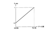
- the optical correction ratio R_ratio is set according to the optical zoom magnification. As shown in FIG. 3, the optical correction ratio R_ratio is set such that R_ratio increases as the zoom position moves from the WIDE end to the TELE end, that is, as the optical zoom magnification increases.
- R_ratio 1, that is, correction is performed using only optical shake correction.
- the ratio between R_ratio and D_ratio is equal to the ratio between the range that can be corrected by optical shake correction and the range that can be corrected by electronic shake correction.
- the focal length of the zoom lens group 31 increases. For this reason, compared with the case where the optical zoom magnification is small, the shake width of the image is increased even if the shake angle of the imaging device 1 is the same.
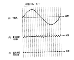
- FIG. 4A a hand-shake of a waveform as shown in FIG. 4A occurs at a normal shutter time of 1/60 seconds between fields and an exposure time of the image sensor 4 of 1/60 seconds.
- FIG. 4B is a diagram showing the magnitude of the shake width for each field when electronic shake correction is performed in this case.
- the shake between the fields can be corrected as shown in FIG. 4B because the shake of the image is corrected by controlling the cutout position of the captured image.
- the field is formed in units of 1/60 second, shake within the field (within the exposure time) cannot be corrected. For this reason, depending on the field, the in-plane fluctuation is large and the image quality is low.
- R_ratio When the optical zoom magnification is small, the degree of image quality degradation in electronic shake correction is smaller than that in high magnification. Therefore, R_ratio is reduced and the distribution ratio D_ratio for electronic shake correction is increased. 1 expands the correctable range that can be corrected.
- the correctable range is determined by the movable range of the prism 2
- the correctable range is determined by the size of the area B for electronic shake correction shown in FIG.
- the most effective use of the two types of correctable ranges is the ratio between the size of the correctable range by optical shake correction and the size of the correctable range by electronic shake correction, and the ratio between R_ratio and D_ratio. Are equal.
- the detected shake angle ⁇ of the imaging device 1 is 5 °.
- R_ratio is set so that R_ratio: D_ratio and Rmax: Dmax are equal, and the correction range of both types is used to the maximum, so that the image shake in the imaging apparatus 1 is reduced.
- the correction range is expanded.
- image shake correction is performed using two methods of optical shake correction and electronic shake correction, and R_ratio is set to be larger as the optical zoom magnification is larger.
- R_ratio and the zoom position is not limited to the linear relationship as shown in FIG. 3 as long as R_ratio increases as the optical zoom magnification increases.
- the detected shake angle ⁇ is larger than the total angle that can be corrected by the two methods when the shake angle ⁇ is distributed to the optical shake correction unit and the electronic shake correction unit based on R_ratio, and 2
- R_ratio may be changed so that the total angle that can be corrected by the two methods becomes large.
- Rmax ⁇ 1 ° is the correctable range by optical shake correction
- Dmax ⁇ 4 ° is the correctable range by electronic shake correction
- a deflection angle ⁇ 5 ° is detected.
- both the optical shake correction and the electronic shake correction are systems that operate independently in the horizontal direction and the vertical direction, and the shake angle ⁇ is also detected for each of the horizontal direction and the vertical direction by the gyro sensor 13. .
- the R_ratio corresponding to the optical zoom magnification is set to a common value in the horizontal direction and the vertical direction, but when changing the R_ratio as described above, it is performed separately in the horizontal direction and the vertical direction.
- the direction is not limited to the horizontal direction and the vertical direction, and may be a predetermined direction and a direction substantially orthogonal to the direction.
- R_ratio corresponding to the optical zoom magnification may be set individually in the horizontal direction and the vertical direction.
- a vertical shake is often caused by shooting while the user walks, and in the TELE end, a vertical shake is rare.
- a horizontal shift is caused by taking a picture while moving in the horizontal direction.
- Directional shake may occur.
- the imaging apparatus according to the second embodiment has the same configuration as that of the imaging apparatus 1 according to the first embodiment, and will be described with reference to FIG.
- the system controller 15 sets the optical correction ratio R_ratio according to the shutter speed (exposure time) of the electronic shutter in the image sensor 4.
- R_ratio 1, that is, correction is set using only optical shake correction.
- R_ratio is set so that R_ratio: D_ratio and Rmax: Dmax are equal.
- the image quality is degraded by the electronic shake correction at the time of a normal shutter with an exposure time of 1/60 seconds.
- the shutter speed is faster than that at the normal shutter, for example, at the fastest shutter with an exposure time of 1/250 seconds, the exposure time per field is short as shown in FIG. And the image quality is less likely to be lower than that during normal shutter.
- R_ratio is set so that R_ratio: D_ratio and Rmax: Dmax are equal, as in the case of the WIDE end in the example of FIG. 3 described in the first embodiment.
- the correction range of the image blur in the imaging apparatus 1 is expanded by setting and utilizing the correctable range of both types to the maximum.
- the shutter speed of the image sensor 4 is set by the system controller 15 based on the brightness of the captured image generated by the signal processing unit 6.
- the longer the exposure time the higher the brightness of the captured image. For example, when the brightness is too high, the brightness is adjusted by shortening the exposure time.
- the system controller 15 supplies a timing control signal to the timing generator 10 so as to drive the image sensor 4 at the set shutter speed.
- the system controller 15 sets R_ratio according to the shutter speed, controls the prism driver 8 to correct the angle obtained by multiplying the shake angle ⁇ of the imaging apparatus 1 by R_ratio by optical shake correction, and sets the shake angle ⁇ .
- the readout control unit 11 is controlled to correct the angle obtained by multiplying D_ratio by electronic shake correction.
- R_ratio according to the shutter speed is set to a common value in the horizontal direction and the vertical direction, but in the same way as in the first embodiment, when changing R_ratio as described above, Separately in the vertical direction.
- R_ratio a value obtained by multiplying R_ratio1 and R_ratio2 may be set as R_ratio.
- R_ratio can be varied more appropriately according to both the zoom position and the shutter speed.
- the present invention provides an imaging apparatus and an image blur correction method that can expand the range in which image blur can be corrected while suppressing deterioration in image quality.
Abstract
Description
図1は、本発明の第1の実施の形態に係る撮像装置の構成を示すブロック図である。図1に示すように、第1の実施の形態に係る撮像装置1は、プリズム2と、レンズユニット3と、撮像素子4と、A/D変換部5と、信号処理部6と、記憶部7と、プリズムドライバ8と、ズームレンズドライバ9と、タイミングジェネレータ10と、読み出し制御部11と、モニタ12と、ジャイロセンサ13と、A/D変換部14と、システムコントローラ15とを備える。
第2の実施の形態に係る撮像装置は、第1の実施の形態の撮像装置1と同様の構成であるため、図1を用いて説明する。
2 プリズム
3 レンズユニット
4 撮像素子
5 A/D変換部
6 信号処理部
7 記憶部
8 プリズムドライバ
9 ズームレンズドライバ
10 タイミングジェネレータ
11 読み出し制御部
12 モニタ
13 ジャイロセンサ
14 A/D変換部
15 システムコントローラ
Claims (14)
- 撮像装置において、
前記撮像装置に入射される被写体からの入射光を光電変換して電気信号を生成する撮像素子と、
前記電気信号に基づいて撮影画像を生成する信号処理部と、
前記撮像装置の振れ角を検出する振れ検出部と、
光学的に前記撮影画像の変倍を行う光学ズーム部と、
前記撮影画像の振れを光学的に補正する光学式振れ補正部と、
前記撮影画像の振れを、前記撮影画像を所定の領域で切り出すことによって補正する電子式振れ補正部と、
前記光学式振れ補正部および前記電子式振れ補正部それぞれへ前記振れ角を分配する比率を、前記光学ズーム部における光学ズーム倍率に応じて設定する設定部と、
設定された前記比率に基づいて前記振れ角を分配し、その分配された振れ角に基づいて前記撮影画像の振れを補正するよう前記光学式振れ補正部および前記電子式振れ補正部を制御する制御部と
を備えることを特徴とする撮像装置。 - 前記設定部は、前記光学ズーム部における光学ズーム倍率が大きいほど、前記振れ角を前記光学式振れ補正部へ分配する比率が大きくなるように、前記比率を設定することを特徴とする請求項1に記載の撮像装置。
- 前記設定部は、前記光学ズーム倍率が最小の場合、前記振れ角を分配する比率を、前記光学式振れ補正部の補正可能範囲の大きさと前記電子式振れ補正部の補正可能範囲の大きさとの比率に応じて設定することを特徴とする請求項1または2に記載の撮像装置。
- 撮像装置において、
前記撮像装置に入射される被写体からの入射光を光電変換して電気信号を生成する撮像素子と、
前記電気信号に基づいて撮影画像を生成する信号処理部と、
前記撮像装置の振れ角を検出する振れ検出部と、
前記撮影画像の振れを光学的に補正する光学式振れ補正部と、
前記撮影画像の所定の領域を切り出すことによって振れを補正する電子式振れ補正部と、
前記光学式振れ補正部および前記電子式振れ補正部それぞれへ前記振れ角を分配する比率を、前記入射光を光電変換する際の前記撮像素子の露光時間に応じて設定する設定部と、
設定された前記比率に基づいて前記振れ角を分配し、その分配された振れ角に基づいて前記撮影画像の振れを補正するよう前記光学式振れ補正部および前記電子式振れ補正部を制御する制御部と
を備えることを特徴とする撮像装置。 - 前記設定部は、前記露光時間が短いほど、前記振れ角を前記光学式振れ補正部へ分配する比率が大きくなるように、前記比率を設定することを特徴とする請求項4に記載の撮像装置。
- 前記設定部は、前記露光時間が前記撮像装置における最も短い露光時間に設定されている場合、前記振れ角を分配する比率を、前記光学式振れ補正部の補正可能範囲の大きさと前記電子式振れ補正部の補正可能範囲の大きさとの比率に応じて設定することを特徴とする請求項4または5に記載の撮像装置。
- 撮像装置において、
前記撮像装置に入射される被写体からの入射光を光電変換して電気信号を生成する撮像素子と、
前記電気信号に基づいて撮影画像を生成する信号処理部と、
前記撮像装置の振れ角を検出する振れ検出部と、
光学的に前記撮影画像の変倍を行う光学ズーム部と、
前記撮影画像の振れを光学的に補正する光学式振れ補正部と、
前記撮影画像の所定の領域を切り出すことによって振れを補正する電子式振れ補正部と、
前記光学式振れ補正部および前記電子式振れ補正部それぞれへ前記振れ角を分配する比率を、前記光学ズーム部における光学ズーム倍率、および、前記入射光を光電変換する際の前記撮像素子の露光時間に応じて設定する設定部と、
設定された前記比率に基づいて前記振れ角を分配し、その分配された振れ角に基づいて前記撮影画像の振れを補正するよう前記光学式振れ補正部および前記電子式振れ補正部を制御する制御部と
を備えることを特徴とする撮像装置。 - 前記設定部は、前記光学ズーム倍率が大きいほど大きくなる第1の比率と、前記露光時間が短いほど小さくなる第2の比率とに基づいて、前記振れ角を前記光学式振れ補正部へ分配する比率を設定することを特徴とする請求項7に記載の撮像装置。
- 前記設定部は、前記光学式振れ補正部と前記電子式振れ補正部との補正可能範囲の大きさの比率に応じて、前記光学ズーム倍率が最小のときにおける前記第1の比率、および前記露光時間が前記撮像装置における最も長い露光時間に設定されているときにおける前記第2の比率を設定することを特徴とする請求項8に記載の撮像装置。
- 前記設定部は、前記振れ検出部で検出された振れ角が、前記光学式振れ補正部と前記電子式振れ補正部とで補正できる合計角度よりも大きく、かつ、前記光学式振れ補正部および前記電子式振れ補正部のいずれかにおいて、前記比率に基づいて分配された角度に対して補正可能範囲に余裕がある場合、前記合計角度が大きくなるように前記比率を変更することを特徴とする請求項1乃至9のいずれか1項に記載の撮像装置。
- 前記設定部は、前記比率を所定の方向と前記所定の方向と略直交する方向とで個別に設定することを特徴とする請求項1乃至10のいずれか1項に記載の撮像装置。
- 撮影画像を光学的に補正する光学式振れ補正部および撮影画像を所定の領域で切り出すことによって補正する電子式振れ補正部を用いて、撮像装置によって撮像される画像の振れを補正する画像振れ補正方法において、
前記撮像装置に入射される被写体からの入射光を光電変換して電気信号を生成する工程と、
前記電気信号に基づいて撮影画像を生成する工程と、
前記撮像装置の振れ角を検出する工程と、
前記光学式振れ補正部および前記電子式振れ補正部それぞれへ前記振れ角を分配する比率を、前記撮像装置の光学ズーム部における光学ズーム倍率に応じて設定する工程と、
設定された前記比率に基づいて前記振れ角を分配し、その分配された振れ角に基づいて前記撮影画像の振れを補正するよう前記光学式振れ補正部および前記電子式振れ補正部を制御する工程と
を含むことを特徴とする画像振れ補正方法。 - 撮影画像を光学的に補正する光学式振れ補正部および撮影画像を所定の領域で切り出すことによって補正する電子式振れ補正部を用いて、撮像装置によって撮像される画像の振れを補正する画像振れ補正方法において、
前記撮像装置に入射される被写体からの入射光を光電変換して電気信号を生成する工程と、
前記電気信号に基づいて撮影画像を生成する工程と、
前記撮像装置の振れ角を検出する工程と、
前記光学式振れ補正部および前記電子式振れ補正部それぞれへ前記振れ角を分配する比率を、前記入射光を光電変換する際の前記撮像装置の撮像素子の露光時間に応じて設定する工程と、
設定された前記比率に基づいて前記振れ角を分配し、その分配された振れ角に基づいて前記撮影画像の振れを補正するよう前記光学式振れ補正部および前記電子式振れ補正部を制御する工程と
を含むことを特徴とする画像振れ補正方法。 - 撮影画像を光学的に補正する光学式振れ補正部および撮影画像を所定の領域で切り出すことによって補正する電子式振れ補正部を用いて、撮像装置によって撮像される画像の振れを補正する画像振れ補正方法において、
前記撮像装置に入射される被写体からの入射光を光電変換して電気信号を生成する工程と、
前記電気信号に基づいて撮影画像を生成する工程と、
前記撮像装置の振れ角を検出する工程と、
前記光学式振れ補正部および前記電子式振れ補正部それぞれへ前記振れ角を分配する比率を、前記撮像装置の光学ズーム部における光学ズーム倍率、および、前記入射光を光電変換する際の前記撮像装置の前記撮像素子の露光時間に応じて設定する工程と、
設定された前記比率に基づいて前記振れ角を分配し、その分配された振れ角に基づいて前記撮影画像の振れを補正するよう前記光学式振れ補正部および前記電子式振れ補正部を制御する工程と
を含むことを特徴とする画像振れ補正方法。
Priority Applications (4)
| Application Number | Priority Date | Filing Date | Title |
|---|---|---|---|
| DE112010005151.8T DE112010005151B4 (de) | 2010-01-18 | 2010-09-17 | Bildaufnahmevorrichtung und bildverwacklungskorrekturverfahren |
| CN201080061667.2A CN102754023B (zh) | 2010-01-18 | 2010-09-17 | 摄像装置以及图像抖动修正方法 |
| US13/522,447 US8896714B2 (en) | 2010-01-18 | 2010-09-17 | Image pickup apparatus and image shake correction method |
| US14/524,474 US9036034B2 (en) | 2010-01-18 | 2014-10-27 | Image pickup apparatus and image shake correction method |
Applications Claiming Priority (2)
| Application Number | Priority Date | Filing Date | Title |
|---|---|---|---|
| JP2010008167A JP5003769B2 (ja) | 2010-01-18 | 2010-01-18 | 撮像装置および画像振れ補正方法 |
| JP2010-008167 | 2010-01-18 |
Related Child Applications (2)
| Application Number | Title | Priority Date | Filing Date |
|---|---|---|---|
| US13/522,447 A-371-Of-International US8896714B2 (en) | 2010-01-18 | 2010-09-17 | Image pickup apparatus and image shake correction method |
| US14/524,474 Division US9036034B2 (en) | 2010-01-18 | 2014-10-27 | Image pickup apparatus and image shake correction method |
Publications (1)
| Publication Number | Publication Date |
|---|---|
| WO2011086728A1 true WO2011086728A1 (ja) | 2011-07-21 |
Family
ID=44304026
Family Applications (1)
| Application Number | Title | Priority Date | Filing Date |
|---|---|---|---|
| PCT/JP2010/066231 WO2011086728A1 (ja) | 2010-01-18 | 2010-09-17 | 撮像装置および画像振れ補正方法 |
Country Status (5)
| Country | Link |
|---|---|
| US (2) | US8896714B2 (ja) |
| JP (1) | JP5003769B2 (ja) |
| CN (1) | CN102754023B (ja) |
| DE (1) | DE112010005151B4 (ja) |
| WO (1) | WO2011086728A1 (ja) |
Cited By (3)
| Publication number | Priority date | Publication date | Assignee | Title |
|---|---|---|---|---|
| CN103167237A (zh) * | 2011-12-14 | 2013-06-19 | Jvc建伍株式会社 | 摄像装置以及图像抖动修正方法 |
| CN103533230A (zh) * | 2012-06-29 | 2014-01-22 | 佳能株式会社 | 摄像设备、光学设备、摄像系统和控制方法 |
| CN108353131A (zh) * | 2016-10-17 | 2018-07-31 | 华为技术有限公司 | 获取图像的方法和终端设备 |
Families Citing this family (27)
| Publication number | Priority date | Publication date | Assignee | Title |
|---|---|---|---|---|
| JP2012055498A (ja) * | 2010-09-09 | 2012-03-22 | Olympus Corp | 画像処理装置、内視鏡装置、画像処理プログラム及び画像処理方法 |
| JP2013138413A (ja) * | 2011-11-28 | 2013-07-11 | Panasonic Corp | 撮像装置 |
| JP6097522B2 (ja) * | 2012-10-22 | 2017-03-15 | キヤノン株式会社 | 像ブレ補正装置及び像ブレ補正方法、撮像装置 |
| JP6097521B2 (ja) | 2012-10-22 | 2017-03-15 | キヤノン株式会社 | 像ブレ補正装置及び像ブレ補正方法、撮像装置 |
| JP5786847B2 (ja) * | 2012-12-19 | 2015-09-30 | カシオ計算機株式会社 | 撮像装置、撮像方法及びプログラム |
| JP6151930B2 (ja) | 2013-02-19 | 2017-06-21 | キヤノン株式会社 | 撮像装置およびその制御方法 |
| JP6074298B2 (ja) * | 2013-03-18 | 2017-02-01 | キヤノン株式会社 | 撮像装置、画像処理装置、及びそれらの制御方法 |
| JP6209002B2 (ja) | 2013-07-16 | 2017-10-04 | キヤノン株式会社 | 撮像装置およびその制御方法 |
| CN103414844B (zh) * | 2013-08-27 | 2016-05-11 | 北京奇艺世纪科技有限公司 | 视频抖动修正方法及装置 |
| JP6170395B2 (ja) | 2013-09-26 | 2017-07-26 | キヤノン株式会社 | 撮像装置およびその制御方法 |
| JP6210824B2 (ja) * | 2013-10-02 | 2017-10-11 | オリンパス株式会社 | 焦点調節装置および焦点調節方法 |
| JP6214316B2 (ja) * | 2013-10-09 | 2017-10-18 | キヤノン株式会社 | 像ブレ補正装置、レンズ装置、撮像装置、像ブレ補正装置の制御方法、プログラム、および、記憶媒体 |
| JP6472176B2 (ja) * | 2014-06-10 | 2019-02-20 | キヤノン株式会社 | 撮像装置、像振れ補正装置、撮像装置の制御方法及び像振れ補正方法 |
| JP6478504B2 (ja) * | 2014-07-16 | 2019-03-06 | キヤノン株式会社 | 撮像装置およびその制御方法 |
| JP2016046747A (ja) * | 2014-08-26 | 2016-04-04 | 富士通テン株式会社 | 画像処理装置、画像処理方法、及び、画像表示システム |
| JP6530602B2 (ja) * | 2014-12-22 | 2019-06-12 | キヤノン株式会社 | 撮像装置及びその制御方法 |
| CN104410134A (zh) * | 2014-12-23 | 2015-03-11 | 深圳市保千里电子有限公司 | 一种带数码照相功能的充电宝 |
| US20170041545A1 (en) * | 2015-08-06 | 2017-02-09 | Invensense, Inc. | Systems and methods for stabilizing images |
| US20170331998A1 (en) * | 2016-05-11 | 2017-11-16 | Htc Corporation | Camera device, method for camera device, and non-transitory computer readable storage medium |
| CN108111744A (zh) * | 2016-11-25 | 2018-06-01 | 努比亚技术有限公司 | 一种拍摄装置和方法 |
| CN106855419B (zh) * | 2016-12-30 | 2020-05-19 | 西安航天精密机电研究所 | 基于加速度计坐标系的直角棱镜标定测试方法 |
| CN107040722B (zh) | 2017-04-27 | 2019-02-15 | 维沃移动通信有限公司 | 一种拍摄方法及移动终端 |
| JP7071099B2 (ja) * | 2017-11-22 | 2022-05-18 | キヤノン株式会社 | 撮像装置 |
| JP2019117977A (ja) | 2017-12-26 | 2019-07-18 | キヤノン株式会社 | 防振制御装置、撮像装置、撮像システム、制御方法及びプログラム |
| CN113170039B (zh) * | 2018-11-29 | 2022-12-16 | 富士胶片株式会社 | 抖动校正控制装置及摄像装置 |
| TWI725836B (zh) * | 2019-05-13 | 2021-04-21 | 香港商立景創新有限公司 | 影像擷取組件以及可攜式電子裝置 |
| KR20220079179A (ko) * | 2020-12-04 | 2022-06-13 | 삼성전자주식회사 | 카메라의 흔들림을 보정하는 방법 및 그 전자 장치 |
Citations (7)
| Publication number | Priority date | Publication date | Assignee | Title |
|---|---|---|---|---|
| JPH0514801A (ja) * | 1990-10-18 | 1993-01-22 | Fuji Photo Film Co Ltd | 手振れ補正装置 |
| JPH07123317A (ja) * | 1993-10-21 | 1995-05-12 | Canon Inc | 防振機能付き撮影装置 |
| JPH07177418A (ja) * | 1993-12-20 | 1995-07-14 | Canon Inc | 画像振れ防止装置 |
| JPH0946575A (ja) * | 1995-07-26 | 1997-02-14 | Sony Corp | 撮像装置 |
| JPH1056592A (ja) * | 1996-08-12 | 1998-02-24 | Sony Corp | 像振れ補正機構 |
| JPH1115035A (ja) * | 1997-06-27 | 1999-01-22 | Nikon Corp | カメラシステム、カメラボディ及び交換レンズ |
| JP2001197357A (ja) * | 2000-01-12 | 2001-07-19 | Hitachi Ltd | 撮像装置 |
Family Cites Families (10)
| Publication number | Priority date | Publication date | Assignee | Title |
|---|---|---|---|---|
| EP0656725B1 (en) * | 1993-12-02 | 2000-03-15 | Canon Kabushiki Kaisha | Image-shake correcting device |
| US6429895B1 (en) * | 1996-12-27 | 2002-08-06 | Canon Kabushiki Kaisha | Image sensing apparatus and method capable of merging function for obtaining high-precision image by synthesizing images and image stabilization function |
| JP2002182260A (ja) | 2000-12-11 | 2002-06-26 | Hitachi Ltd | 撮像装置 |
| US8208017B2 (en) * | 2003-12-26 | 2012-06-26 | Panasonic Corporation | Imaging device, product package, and semiconductor integrated circuit |
| JP2005215388A (ja) * | 2004-01-30 | 2005-08-11 | Canon Inc | 交換レンズ及びそれを用いたカメラシステム |
| JP4022595B2 (ja) | 2004-10-26 | 2007-12-19 | コニカミノルタオプト株式会社 | 撮影装置 |
| JP4766320B2 (ja) | 2006-02-06 | 2011-09-07 | カシオ計算機株式会社 | 撮像装置及びそのプログラム |
| JP4400611B2 (ja) * | 2006-10-26 | 2010-01-20 | カシオ計算機株式会社 | 撮像装置、ブレ補正方法、およびプログラム |
| JP2009053226A (ja) | 2007-08-23 | 2009-03-12 | Hoya Corp | 撮影システムおよびデジタルカメラ |
| JP5328307B2 (ja) * | 2008-11-14 | 2013-10-30 | キヤノン株式会社 | 振れ補正機能を有する撮影装置及びその制御方法 |
-
2010
- 2010-01-18 JP JP2010008167A patent/JP5003769B2/ja active Active
- 2010-09-17 WO PCT/JP2010/066231 patent/WO2011086728A1/ja active Application Filing
- 2010-09-17 CN CN201080061667.2A patent/CN102754023B/zh active Active
- 2010-09-17 US US13/522,447 patent/US8896714B2/en active Active
- 2010-09-17 DE DE112010005151.8T patent/DE112010005151B4/de active Active
-
2014
- 2014-10-27 US US14/524,474 patent/US9036034B2/en active Active
Patent Citations (7)
| Publication number | Priority date | Publication date | Assignee | Title |
|---|---|---|---|---|
| JPH0514801A (ja) * | 1990-10-18 | 1993-01-22 | Fuji Photo Film Co Ltd | 手振れ補正装置 |
| JPH07123317A (ja) * | 1993-10-21 | 1995-05-12 | Canon Inc | 防振機能付き撮影装置 |
| JPH07177418A (ja) * | 1993-12-20 | 1995-07-14 | Canon Inc | 画像振れ防止装置 |
| JPH0946575A (ja) * | 1995-07-26 | 1997-02-14 | Sony Corp | 撮像装置 |
| JPH1056592A (ja) * | 1996-08-12 | 1998-02-24 | Sony Corp | 像振れ補正機構 |
| JPH1115035A (ja) * | 1997-06-27 | 1999-01-22 | Nikon Corp | カメラシステム、カメラボディ及び交換レンズ |
| JP2001197357A (ja) * | 2000-01-12 | 2001-07-19 | Hitachi Ltd | 撮像装置 |
Cited By (6)
| Publication number | Priority date | Publication date | Assignee | Title |
|---|---|---|---|---|
| CN103167237A (zh) * | 2011-12-14 | 2013-06-19 | Jvc建伍株式会社 | 摄像装置以及图像抖动修正方法 |
| CN103167237B (zh) * | 2011-12-14 | 2016-01-20 | Jvc建伍株式会社 | 摄像装置以及图像抖动修正方法 |
| CN103533230A (zh) * | 2012-06-29 | 2014-01-22 | 佳能株式会社 | 摄像设备、光学设备、摄像系统和控制方法 |
| CN103533230B (zh) * | 2012-06-29 | 2016-12-28 | 佳能株式会社 | 摄像设备、光学设备、摄像系统和控制方法 |
| CN108353131A (zh) * | 2016-10-17 | 2018-07-31 | 华为技术有限公司 | 获取图像的方法和终端设备 |
| US11057565B2 (en) | 2016-10-17 | 2021-07-06 | Huawei Technologies Co., Ltd. | Image obtaining method and terminal device |
Also Published As
| Publication number | Publication date |
|---|---|
| CN102754023A (zh) | 2012-10-24 |
| US9036034B2 (en) | 2015-05-19 |
| US20120293672A1 (en) | 2012-11-22 |
| DE112010005151B4 (de) | 2019-05-09 |
| US20150092068A1 (en) | 2015-04-02 |
| JP5003769B2 (ja) | 2012-08-15 |
| CN102754023B (zh) | 2015-07-15 |
| DE112010005151T5 (de) | 2012-11-15 |
| JP2011145604A (ja) | 2011-07-28 |
| US8896714B2 (en) | 2014-11-25 |
Similar Documents
| Publication | Publication Date | Title |
|---|---|---|
| JP5003769B2 (ja) | 撮像装置および画像振れ補正方法 | |
| JP4717748B2 (ja) | カメラ本体及びそれを有するカメラシステム | |
| JP6530602B2 (ja) | 撮像装置及びその制御方法 | |
| US10136064B2 (en) | Image processing apparatus and method of controlling image processing apparatus | |
| US8279290B2 (en) | Blur correcting image pickup apparatus and control method | |
| JP6472176B2 (ja) | 撮像装置、像振れ補正装置、撮像装置の制御方法及び像振れ補正方法 | |
| US20110157381A1 (en) | Image capturing apparatus and control method thereof | |
| WO2010004764A1 (ja) | 撮像装置 | |
| JP2017152996A (ja) | 撮像システムおよびその制御方法、撮像装置、レンズ装置 | |
| JP4508991B2 (ja) | 撮像装置 | |
| JP2019128362A (ja) | 撮像装置 | |
| JP2018056753A (ja) | カメラコントローラ、画像処理モジュール、および半導体システム | |
| JP2007140064A (ja) | 像振れ補正機能付き光学機器 | |
| JP2015099216A (ja) | 光学機器 | |
| JP5426952B2 (ja) | 像振れ補正装置及びその制御方法、光学機器、撮像装置 | |
| JP5886623B2 (ja) | 撮像装置およびその制御方法 | |
| JPH1127573A (ja) | 画像動き補正装置 | |
| US8817127B2 (en) | Image correction device for image capture device and integrated circuit for image correction device | |
| JP2003101866A (ja) | 光学装置 | |
| JP2016050973A (ja) | 撮像装置及びその制御方法 | |
| JP4258383B2 (ja) | 撮像装置 | |
| JP2021033015A (ja) | 像ブレ補正装置及びその制御方法、プログラム、記憶媒体 | |
| JP7214424B2 (ja) | 撮像装置およびその制御方法 | |
| JPH11266390A (ja) | 撮像装置 | |
| JP2005130361A (ja) | 光学機器 |
Legal Events
| Date | Code | Title | Description |
|---|---|---|---|
| WWE | Wipo information: entry into national phase |
Ref document number: 201080061667.2 Country of ref document: CN |
|
| 121 | Ep: the epo has been informed by wipo that ep was designated in this application |
Ref document number: 10843085 Country of ref document: EP Kind code of ref document: A1 |
|
| DPE1 | Request for preliminary examination filed after expiration of 19th month from priority date (pct application filed from 20040101) | ||
| WWE | Wipo information: entry into national phase |
Ref document number: 13522447 Country of ref document: US |
|
| WWE | Wipo information: entry into national phase |
Ref document number: 112010005151 Country of ref document: DE Ref document number: 1120100051518 Country of ref document: DE |
|
| 122 | Ep: pct application non-entry in european phase |
Ref document number: 10843085 Country of ref document: EP Kind code of ref document: A1 |