WO2011074157A1 - 画像生成装置及び画像生成方法 - Google Patents
画像生成装置及び画像生成方法 Download PDFInfo
- Publication number
- WO2011074157A1 WO2011074157A1 PCT/JP2010/005377 JP2010005377W WO2011074157A1 WO 2011074157 A1 WO2011074157 A1 WO 2011074157A1 JP 2010005377 W JP2010005377 W JP 2010005377W WO 2011074157 A1 WO2011074157 A1 WO 2011074157A1
- Authority
- WO
- WIPO (PCT)
- Prior art keywords
- data
- animation
- screen
- display
- image
- Prior art date
Links
Images


Classifications
-
- G—PHYSICS
- G06—COMPUTING OR CALCULATING; COUNTING
- G06T—IMAGE DATA PROCESSING OR GENERATION, IN GENERAL
- G06T13/00—Animation
-
- H—ELECTRICITY
- H04—ELECTRIC COMMUNICATION TECHNIQUE
- H04N—PICTORIAL COMMUNICATION, e.g. TELEVISION
- H04N21/00—Selective content distribution, e.g. interactive television or video on demand [VOD]
- H04N21/40—Client devices specifically adapted for the reception of or interaction with content, e.g. set-top-box [STB]; Operations thereof
- H04N21/43—Processing of content or additional data, e.g. demultiplexing additional data from a digital video stream; Elementary client operations, e.g. monitoring of home network or synchronising decoder's clock; Client middleware
- H04N21/431—Generation of visual interfaces for content selection or interaction; Content or additional data rendering
- H04N21/4312—Generation of visual interfaces for content selection or interaction; Content or additional data rendering involving specific graphical features, e.g. screen layout, special fonts or colors, blinking icons, highlights or animations
-
- H—ELECTRICITY
- H04—ELECTRIC COMMUNICATION TECHNIQUE
- H04N—PICTORIAL COMMUNICATION, e.g. TELEVISION
- H04N21/00—Selective content distribution, e.g. interactive television or video on demand [VOD]
- H04N21/40—Client devices specifically adapted for the reception of or interaction with content, e.g. set-top-box [STB]; Operations thereof
- H04N21/43—Processing of content or additional data, e.g. demultiplexing additional data from a digital video stream; Elementary client operations, e.g. monitoring of home network or synchronising decoder's clock; Client middleware
- H04N21/443—OS processes, e.g. booting an STB, implementing a Java virtual machine in an STB or power management in an STB
- H04N21/4438—Window management, e.g. event handling following interaction with the user interface
Definitions
- the present invention relates to an image processing technique for generating an animation image (moving image) using vector format data.
- the vector graphics data includes parameters representing information such as the coordinates of the start and end points of the curve to be displayed, color, size, and shape, and performs deformation processing such as enlargement, reduction, or rotation of the image using the parameters. Therefore, a high quality drawing output can be obtained. Further, the vector format data is suitable for displaying an animation image because the data size is small compared to raster format data (raster graphics data) such as bitmap data.
- a technique for generating an animation image using vector graphics data is disclosed in, for example, Japanese Patent Application Laid-Open No. 2007-121758 (Patent Document 1).
- the on-screen display (OSD: On Screen Display) is a setting screen for the user to perform various settings such as image quality, display position, and brightness, as well as screen display of additional information such as date, time, title, and program information. Used for display.
- OSD On Screen Display
- additional information such as date, time, title, and program information.
- the screen display device disclosed in Patent Document 1 refers to the scene resource ID table held in the vector graphics data, identifies the hierarchical screen corresponding to the input key type, and displays this hierarchical screen.
- An animation image is generated according to the corresponding scene playback script.
- an object of the present invention is to provide an image generation apparatus and an image generation method capable of suppressing the size of a storage area necessary for displaying an animation image.
- An image generation apparatus includes a first data storage unit storing a plurality of vectorized graphics data, and a plurality of types of display operation patterns for any one of the plurality of graphics data.
- a second data storage unit storing operation information defined in units of frames using a transformation matrix; designating graphics data to be displayed on a display screen from the plurality of graphics data; and the plurality of types
- a third data storage unit that stores a plurality of screen configuration information for designating display operation patterns to be assigned to the graphics data to be displayed, and a plurality of screen configuration information.
- the graphics data is acquired from the first data storage unit based on the screen configuration information and the acquisition
- a display operation pattern to be applied to the graphics data is acquired from the third data storage unit, and an animation image of the acquired graphics data is obtained based on the acquired graphics data and the acquired display operation pattern.
- an image generation unit for generating the image.
- An image generation method specifies graphics data to be displayed on a display screen from a plurality of vectorized graphics data, and a plurality of types of data targeted for any one of the plurality of graphics data.
- a plurality of screen configurations comprising: a first data storage unit that is configured; and a second data storage unit that stores operation information defining the plurality of types of display operation patterns in units of frames using a conversion matrix.
- the size of the storage area necessary for displaying an animation image can be suppressed.
- FIG. 1 It is a functional block diagram which shows schematic structure of the image display apparatus of Embodiment 1 which concerns on this invention. It is the schematic which shows an example of the display screen containing an animation image. It is the schematic which shows an example of the display screen containing an animation image.
- (A) is a figure which shows an example of the content of an animation table
- (B) is a figure for demonstrating the format of the data sequence in an animation table. It is a figure which shows an example of the data structure of screen structure information roughly. It is a figure which shows an example of a structure of animation data roughly. It is a figure which shows an example of a screen display list roughly.
- (A), (B), (C) is a diagram illustrating a storage area of the OSD memory according to the first embodiment.
- FIG. 3 is a flowchart schematically showing a procedure of image generation processing according to the first embodiment.
- (A), (B), (C) is a figure which illustrates the storage area
- 10 is a flowchart schematically showing a procedure of screen registration processing according to the second embodiment.
- 10 is a flowchart schematically showing a procedure of image generation processing according to the second embodiment.
- FIG. 1 is a functional block diagram showing a schematic configuration of an image display device 1 according to Embodiment 1 of the present invention.
- the image generation apparatus 1 includes a screen change request unit 11, a control unit 12, data storage units 13, 14, 15, an animation data generation unit 16, a drawing unit 17, and an OSD (On Screen Display).
- a memory 18 and an image display unit 19 are provided.
- the control unit 12, the animation data generation unit 16, and the drawing unit 17 constitute an image generation unit.
- the screen change request unit 11 has a function of receiving, for example, input data by a user's key operation and text data transferred from an external device (not shown).
- the screen change request unit 11 includes a key input device (for example, a keyboard or a remote controller), a pointing device (for example, a mouse), and an interface circuit having a communication function with an external device.
- the screen change request unit 11 can also transfer information input by the user to the control unit 12.
- the image generation device 1 has a function of displaying an animation image on the display screen of the image display unit 19.
- 2A and 2B and FIGS. 3A and 3B are schematic diagrams illustrating an example of display screen data including an animation image.
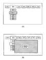
- the display screen displays the first element objects A00, B00, C00, D00, E00, F00, G00, and the second element object corresponding to the object A00.
- A10, A20, A30, A40, A50, A60 are displayed.
- the state of FIG. 1A shows a state in which the object A00 is selected, and the lower-order object A10 is enlarged and displayed.
- FIG. 2A to the state shown in FIG.
- the second element objects A10, A20, A30, A40, A50, A60 corresponding to the object A00 disappear, and the second element objects B10, B20, B30, B40, and B50 are displayed.
- the state in FIG. 2B shows a state where the object B00 is selected.
- the display screen changes from the state shown in FIG. 2B to the state shown in FIG.
- the state in FIG. 3A shows a state where the object B20 is selected, and the object B20 is displayed in an enlarged manner.
- the display screen changes from the state shown in FIG. 3A to the state shown in FIG.
- a third element object B21 corresponding to the object B20 is displayed on the display screen of FIG.
- the first element objects A00, B00, C00, D00, E00, F00, and G00 are always displayed.
- the second element object (for example, B10, B20,...) Is displayed when the corresponding higher level object (for example, B00) is selected, and is not displayed when the corresponding higher level object is not selected.
- the object B21 of the third element is displayed in a predetermined area so as to overwrite the objects B10, B20, B30, B40, and B50 of the second element.
- the control unit 12, the animation data generation unit 16, and the drawing unit 17 include, for example, a microprocessor such as a CPU, a ROM (Read Only Memory), a RAM (Random Access Memory), a timer circuit, an input / output interface, and a dedicated processing unit. It can be configured with a circuit. All or some of the functions of the control unit 12, the animation data generation unit 16, and the drawing unit 17 may be realized by hardware, or may be realized by a computer program executed by a microprocessor. When all or a part of the functions of the control unit 12, the animation data generation unit 16, and the drawing unit 17 are realized by a computer program (including an executable file), the microprocessor can read from the computer-readable recording medium to the computer. The function can be realized by loading and executing a program or an executable file corresponding to the program.
- a microprocessor such as a CPU, a ROM (Read Only Memory), a RAM (Random Access Memory), a timer circuit, an input / output interface, and a dedicated processing
- the data storage units 13, 14, and 15 can be configured using a non-volatile memory, an HDD (hard disk drive), or a memory such as an optical disk.
- the data storage units 13, 14, and 15 may be configured in separate memory storage areas, or may be configured in different storage areas in the same memory.
- the data storage unit 13 stores a plurality of vectorized object data 130 1 ,..., 130 N (N is a positive integer of 2 or more). These object data 130 1 ,..., 130 N are data serving as materials for generating an animation image, and include vectorized graphics data and vector font data (outline font data).
- the data storage unit 14 stores an animation table (motion information) 140 that defines a plurality of types of display motion patterns (animation types) for the object data 130 1 ,..., 130 N in units of frames using a transformation matrix.
- the transformation matrix is used for matrix calculation for enlarging / reducing, rotating or translating an object image represented by graphics data.
- the object data 130 1 ,..., 130 N is static data that does not include display information indicating temporal changes, and the display operation pattern described in the animation table 140 is the static object data 130. 1 ,..., 130 N is information for giving an animation operation.
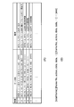
- FIG. 4A is a diagram showing an example of the contents of the animation table 140
- FIG. 4B is a diagram for explaining the format of the data string in the animation table 140.
- numbers “1”, “2”,... Indicating the types of display operation patterns and “data strings” corresponding to the respective numbers are described.
- the item “action” corresponding to each number is for explaining the action of the corresponding data string, and is not necessarily included in the actual animation table 140.
- At least one data element [frame No, action, data, data,...] Exists.
- Each of the data elements [frame No., action, data, data,...] Defines an animation operation.
- “Frame No” specifies the number of a specific frame in a series of frames
- “action” is the parallel of object data in the specified frame. This is a number that designates one of movement, enlargement / reduction, and rotation.
- Data designates the x coordinate and y coordinate of the movement destination when the object data is translated, When enlarging / reducing, the enlargement ratio in the vertical direction and the horizontal direction is designated, and when rotating the object data, the rotation angle is designated.
- the data storage unit 15 stores screen configuration information 150 1 ,..., 150 M.
- Each of the screen configuration information 150 1 ,..., 150 M specifies graphics data to be displayed on the display screen of the image display unit 19 from among the object data 130 1 to 130 N , and is shown in FIG.
- a display operation pattern assigned to the graphics data to be displayed is specified from among a plurality of types of display operation patterns.
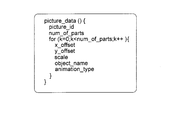
- FIG. 5 is a diagram schematically showing an example of the data structure of each screen configuration information 150 m (m is any one of 1 to N).
- “picture_id” is a picture ID (picture identifier) assigned to each display screen data
- number_of_parts” is the number (in other words, the number of object data 130 1 to 130 N constituting each display screen data.
- “X_offset” is the x coordinate of the drawing position of the kth object data 130 k on the display screen
- y_offset is the y coordinate of the drawing position of the object data 130 k on the display screen
- “scale”. is a magnification of the enlargement / reduction of the object data 130 k
- object_name is a name which specifies the object data 130 k
- animation_type is a type of display operation pattern applied to the object data 130 k The number to specify.
- the animation data generation unit 16 assigns the object data 130 p from the data storage units 13 and 14 to this. It acquires the display operation pattern, has the ability to dynamically generate the animation data and a display control command for the object data 130 p and the object data 130 p.
- the object data 130 p is specified by "object_name” (FIG. 5) of the screen configuration information 0.99 i
- display operation pattern is intended to be specified by "animation_type” (FIG. 5) of the screen configuration information 0.99 i is there.
- the control unit 12 expands the animation data in the storage area of the OSD memory 18.
- FIG. 6 is a diagram schematically showing an example of the configuration of animation data for one piece of object data.
- the animation data includes a display control command group (coordinate conversion command group) 160C and object data 160J specified by “obj_id” (object ID).
- the display control command group 160C in FIG. 6 corresponds to the first type of display operation pattern in FIG.
- the transformation matrix MATRIX_A means to expand / reduce the object data 130 1 using Matrix_E
- MATRIX_A 1.1
- “End” is a command for ending the display of the animation image.
- the control unit 12 has a function (list generation function) for generating a screen display list that determines a drawing position on each display screen of the object data 130 p specified by the screen configuration information 150 i .
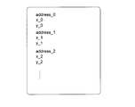
- FIG. 7 is a diagram schematically illustrating an example of the screen display list.
- the screen display list includes “address_i” indicating the start address in the storage area of the OSD memory 18 for the i-th animation data and the drawing position of the object data corresponding to the i-th animation data. It consists of a combination of “x_i” indicating the x coordinate and “y_0” indicating the y coordinate of the drawing position of the object data corresponding to the i-th animation data.
- the control unit 12 expands the data of the screen display list in the storage area of the OSD memory 18.
- the drawing unit 17 is a graphics engine that processes vector format data, and operates in response to an instruction to start playback, switch playback content, or stop playback from the control unit 12.
- the drawing unit 17 When receiving a reproduction start instruction from the control unit 12, the drawing unit 17 generates display screen data including an animation image based on the screen display list developed in the OSD memory 18 and the animation data group corresponding thereto. To do.
- the generated display screen data is output and displayed on the image display unit 19.
- FIGS. 8A, 8 ⁇ / b> B, and 8 ⁇ / b> C are diagrams illustrating storage areas of the OSD memory 18 according to the first embodiment.
- OSD memory 18 includes a frame buffer comprising a storage area of the first surface P A and the second surface P B.
- the other surface is used as a data storage area to be displayed next. Used.
- FIG. 8 (A) shows that one of the first surface P A and the second surface P B is used as a data storage area for the currently displayed data, the other surface is used as a data storage area to be displayed next. Used.
- the storage area of the first surface P A includes a storage area SA0 screen display list Da0, a storage area SA1 of the first element for the animation data Da1, the second element for the animation data It consists of a storage area SA2 for Da2, a storage area SA3 for animation data for third element Da3, and a storage area SA4 for telop display data Da4.
- the storage area SA1 is, for example, the first element objects A00, B00, C00, D00, E00, F00, G00 (FIGS. 2A, 2B and 3A, 3B).
- the storage area SA2 is an area for the second element object (for example, A10, A20), and the storage area SA3 is an area for the third element object (for example, B21).
- the telop display storage area SA4 is used for telop display of vector fonts.
- the storage areas SA1, SA2 and SA3 have the same structure.
- animation data for the first element is stored in the areas specified by the relative addresses “0”, “Offset — 01”, “Offset — 02”,..., “Offset — 06”, respectively.
- Da [A00], Da [B00], Da [C00], Da [D00], Da [E00], Da [F00], Da [G00] are stored.
- the animation data Da [X10] and Da [X20] for the second element are respectively stored in the areas specified by the relative addresses “0”, “Offset — 11”, “Offset — 12”,..., “Offset — 15”.
- Da [X30], Da [X40], Da [X50], Da [X60], Da [X70] (where X10 to X70 are A10 to A70, B10 to B70, C10 to C70, Any one of D10 to D70, E10 to E70, F10 to F70, and G10 to G70).
- the first element objects A00, B00, C00, D00, E00, F00, and G00 are always displayed.
- Animation data for the second elements X10 to X70 corresponding to the object of the first element in the selected state is expanded in the storage area SA2. Furthermore, one object among the second elements X10 to X70 can be set in a selected state, and the other objects can be set in a non-selected state.
- FIG. 9 is a flowchart schematically showing a procedure of image generation processing according to the first embodiment.
- the control unit 12 starts the image generation process of FIG. 9 when there is a screen change request from the screen change request unit 11.
- the control unit 12 executes the procedure after step S101, and when it is determined that this screen change request is a telop display request. Executes the procedure after step S109 (step S100).
- the control unit 12 obtains the screen configuration information 0.99 q specified in the screen switching request from the data storage unit 15, the screen New animation data to be newly generated is specified from the animation data specified by the configuration information 150 q (step S101). Specifically, when the screen switching request specifies a picture ID, the control unit 12 includes the components of the screen configuration information 150 q corresponding to the picture ID and the screen configuration information 150 r ( Compare with the component of r ⁇ q). Based on the comparison result, the control unit 12 does not need to generate the same animation data as the existing animation data already developed in the OSD memory 18 among the animation data specified by the screen configuration information 150 q.
- step S101 Determination is made and new animation data is specified (step S101). Then, the control unit 12 notifies the animation data generation unit 16 of information necessary for generating new animation data (object data name and display operation pattern type), and sends an animation data generation instruction to the animation data generation unit 16. .
- Animation data generation unit 16 in response to the generation instruction from the control unit 12, acquires the information of one or more of display operation pattern assigned to this and the object data 130 p from the data storage unit 13, 14 Then, new animation data including the object data 130 p and a display control command corresponding thereto is generated, and the data size of the new animation data is notified to the control unit 12 (step S102).
- the animation data generation unit 16 can assign a plurality of types of display operation patterns to one object data. Thereby, an animation image of an object that moves in a complicated manner can be generated.
- the control unit 12 Upon receiving the notification from the animation data generation unit 16, the control unit 12 specifies the data size of all the animation data constituting the next display screen, and the animation data generated by the animation data generation unit 16 is stored in the OSD memory. 18 is expanded in the storage area for the next display screen (step S103).
- the control unit 12 transfers the existing animation data determined not to be generated in step S101 from the current display screen storage area of the OSD memory 18 to the next display screen storage area (for example, in the region of Figure 8 the first face second plane P B from the region in the P a of (a)) to copy.
- the time required to newly generate existing animation data and transfer it to the OSD memory 18 can be reduced, so that the time required to display the next display screen data can be reduced.
- control unit 12 refers to the screen configuration information 150 q to acquire the drawing position coordinates of all animation data constituting the next display screen data, and generates a screen display list for the next display screen (Step S1). S104).
- control unit 12 expands the data of the screen display list to the area for the next display screen in the OSD memory 18 (step S105), and sends a reproduction content switching request to the drawing unit 17 (step S106). .
- the drawing unit 17 In response to the playback content switching request from the control unit 12, the drawing unit 17 refers to the screen display list specified by the control unit 12, acquires individual animation data specified by the screen display list, and executes these animations.
- the object data included in the data is decoded to generate an animation image (step S107).
- the image display unit 19 performs display processing of display screen data including the animation image generated by the drawing unit 17 (step S108).
- step S100 when it is determined in step S100 that the screen change request is a telop display request, the control unit 12 sends the text data specified by the telop display request and a generation request for the telop data to the animation data generation unit 16.
- the animation data generation unit 16 reads a series of vector font data (outline font data) corresponding to the text data from the data storage unit 13, and generates animation data based on the read vector font data series. After that, a completion notification is sent to the control unit 12 (step S109).
- the animation data generation unit 16 divides the read vector font data series into a plurality of vector font data groups VP 1 ,..., VP K (K is a positive integer of 2 or more) in a certain number of characters. . Then, the animation data generation unit 16, these vector font data group VP 1, ..., and VP K, the vector font data group VP 1, ..., is repeatedly moved from one end of the display screen strings VP K to the other Animation data including display control commands is generated.
- the display control command uses the vector font after the head of the character string of the n-th vector font data group VP n (n is one of 1 to K-1) is arranged in the lower right area of the display screen.
- the character string of the vector font data group VP n + 1 is constant from the lower right area to the left for each frame. It is configured to include a command for translating by width and a command for deleting a character string moved outside the effective area of the display screen.
- the control unit 12 expands the animation data generated by the animation data generation unit 16 in a predetermined area for the next display screen of the OSD memory 18 (step S110), and the current display screen of the OSD memory 18 A screen display list is read (step S111). Further, the control unit 12 adds information on the drawing position of the vector font data to the read screen display list to generate a new screen display list (step S104), and issues a playback content switching request to the drawing unit 17. Send (step S106). After that, the drawing unit 17 receives the reproduction content switching request from the control unit 12, refers to the screen display list specified by the control unit 12, acquires individual animation data specified by the screen display list, The object data and vector font data included in the animation data are decoded to generate an animation image (step S107). The image display unit 19 performs display processing of display screen data including the animation image generated by the drawing unit 17 (step S108). As a result, the character string is displayed as a telop on the display screen of the image display unit 19.
- the control unit 12 displays a telop when expanding the animation data in the area for the next display screen in the OSD memory 18 in step S103.
- the animation data for use exists in the current display screen area of the OSD memory 18
- the telop display animation data is copied from the current display screen area to the next display screen area. be able to.
- the control unit 12 can store and use information indicating whether or not the telop display animation data exists in the current display screen area of the OSD memory 18.
- step S104 the control unit 12 adds information related to the drawing position of the vector font data to the screen display list for the next display screen. Thereby, the telop display can be continued even when the screen is switched.
- the image generation apparatus 1 performs the display operation assigned to the object data 130 p from the data storage units 13 and 14 based on the designated screen configuration information 150 q. It acquires the pattern, it is possible to generate an animated image on the basis of the combination of the display operation pattern and object data 130 p. For this reason, since the data storage unit 13 only needs to store the minimum necessary object data 130 1 to 130 N , the size of the storage area necessary for generating the animation image can be reduced.
- the animation data generation unit 16 since the dynamically generated animation data corresponding to each object data 130 p, for each display screen, it is not necessary to store the vectorized animation data has been previously, for OSD There is an advantage that the storage capacity (size) of the memory 18 can be suppressed. Furthermore, the control unit 12 dynamically generates a screen display list that determines a drawing position on the display screen of the object data 130 p to which the animation operation is added, and the drawing unit 17 uses a combination of the screen display list and the animation data. Since an animation image is generated based on this, a complex and diverse animation image can be generated.
- FIG. 10 a second embodiment according to the present invention will be described.
- the basic configuration of the image display apparatus according to the second embodiment is the same as that of the image generation apparatus 1 according to the first embodiment.
- the structure of the OSD memory 18 is as shown in FIGS. 10 (A), (B), and (C).
- FIG. 10 (A) OSD memory 18 of the second embodiment, FIG. 8 (A) ⁇ (C) on the first surface the same storage as the storage area of the P A and a second surface P B shown
- it further has a storage area for a plurality of surfaces P C , P D ,. These planes P C , P D ,...
- FIG. 11 is a flowchart schematically showing a procedure of screen registration processing according to the second embodiment.
- the screen change request unit 11 outputs a screen registration request together with the picture ID to the control unit 12, the screen registration process in FIG. 11 is started.
- Control unit 12 when receiving a screen registration request from the screen change request unit 1 (step S201), the components of the screen configuration information 0.99 q corresponding to the designated picture ID, the screen corresponding to the current display screen configuration The component of the information 150 r (r ⁇ q) is compared. Based on the comparison result, the control unit 12 does not need to generate the same animation data as the existing animation data already developed in the OSD memory 18 among the animation data specified by the screen configuration information 150 q. Judgment and new animation data are specified (step S202). Then, the control unit 12 notifies the animation data generation unit 16 of information necessary for generating new animation data (object data name and display operation pattern type), and sends an animation data generation instruction to the animation data generation unit 16. .
- Animation data generation unit 16 in response to the generation instruction from the control unit 12, acquires the information of one or more of display operation pattern assigned to this and the object data 130 p from the data storage unit 13, 14 , it generates a new animation data and a display control commands for this and the object data 130 p, and notifies the data size of the new animation data to the control unit 12 (step S203).
- the control unit 12 Upon receiving the notification from the animation data generation unit 16, the control unit 12 specifies the data size of all the animation data constituting the registration screen, and the animation data generated by the animation data generation unit 16 is stored in the OSD memory 18.
- the data is expanded in a registration screen storage area (for example, any one of the planes P B , P C , and P D in FIG. 10) (step S204).
- the control unit 12 copies the existing animation data determined not to be generated in step S202 from the current display screen storage area of the OSD memory 18 to the registration screen storage area.
- the time required to newly generate existing animation data and transfer it to the OSD memory 18 can be reduced, so that the time required for the screen registration process can be reduced.
- control unit 12 refers to the screen configuration information 150 q to acquire the drawing position coordinates of all the animation data constituting the registration screen and generate a screen display list for the registration screen (step S205).
- control unit 12 expands the data of the screen display list in the registration screen area of the OSD memory 18 (step S206), and ends the registration screen processing.
- FIG. 12 is a flowchart schematically showing a procedure of image generation processing according to the second embodiment.
- the control unit 12 starts the image generation process in FIG. 11 when a screen change request is received from the screen change request unit 11.
- control unit 12 determines that the screen change request received from the screen change request unit 11 is a screen switching request
- the control unit 12 executes the procedure after step S207, and determines that the screen change request is a telop display request. Executes the procedure after step S109 (step S100).
- the procedure of steps S109 to S111 in FIG. 12 is the same as the procedure of steps S109 to S111 in FIG.
- Step S100 When the screen change request from the screen change request unit 11 is a screen switching request (Step S100), the control unit 12 checks whether or not the designated picture ID has been registered (Step S207). When the designated picture ID is not registered, that is, display screen data (animation data and screen display list) corresponding to the designated picture ID is not stored in the OSD memory 18 by the screen registration process of FIG. If so (NO in step S207), the control unit 12 executes the procedure of steps S101 to S108.
- the procedure of steps S101 to S108 in FIG. 12 is the same as the procedure of steps S101 to S108 in FIG.
- step S207 the control unit 12 sends a reproduction content switching request to the drawing unit 17 (step S208).
- the drawing unit 17 Upon receiving a switching request from the control unit 12, the drawing unit 17 refers to the screen display list specified by the control unit 12, acquires individual animation data specified by the screen display list, and stores these animation data in the animation data.
- the object data included is decoded to generate an animation image (step S209).
- the image display unit 19 performs display processing of display screen data including the animation image generated by the drawing unit 17 (step S210).
- the screen display list and animation data are expanded in advance in the OSD memory 18 in the screen registration process of FIG. be able to. That is, when a screen switching request from the screen change request unit 11 is generated and the designated picture ID has been registered (YES in steps S100 and S207), switching to the registration screen can be performed instantaneously. .
- the various embodiments according to the present invention have been described above with reference to the drawings.
- the first and second embodiments can be applied to consumer devices such as television devices, in-vehicle devices, in-train display devices, etc., in which the number of combinations of display screens and objects (display items) is enormous.
Landscapes
- Engineering & Computer Science (AREA)
- Multimedia (AREA)
- Signal Processing (AREA)
- Physics & Mathematics (AREA)
- General Physics & Mathematics (AREA)
- Theoretical Computer Science (AREA)
- Human Computer Interaction (AREA)
- Software Systems (AREA)
- Processing Or Creating Images (AREA)
- Controls And Circuits For Display Device (AREA)
Priority Applications (6)
| Application Number | Priority Date | Filing Date | Title |
|---|---|---|---|
| CN201080056633.4A CN102656610B (zh) | 2009-12-15 | 2010-09-01 | 图像生成装置以及图像生成方法 |
| KR1020127015328A KR101364827B1 (ko) | 2009-12-15 | 2010-09-01 | 화상 생성 장치 및 화상 생성 방법 |
| US13/513,521 US8902237B2 (en) | 2009-12-15 | 2010-09-01 | Image generating apparatus and image generating method |
| HK12112937.7A HK1172132B (en) | 2009-12-15 | 2010-09-01 | Device and method for image generation |
| SG2012038378A SG181047A1 (en) | 2009-12-15 | 2010-09-01 | Device and method for image generation |
| EP10837195.6A EP2515275A4 (en) | 2009-12-15 | 2010-09-01 | Device and method for image generation |
Applications Claiming Priority (2)
| Application Number | Priority Date | Filing Date | Title |
|---|---|---|---|
| JP2009-283642 | 2009-12-15 | ||
| JP2009283642A JP5008714B2 (ja) | 2009-12-15 | 2009-12-15 | 画像生成装置及び画像生成方法 |
Publications (1)
| Publication Number | Publication Date |
|---|---|
| WO2011074157A1 true WO2011074157A1 (ja) | 2011-06-23 |
Family
ID=44166931
Family Applications (1)
| Application Number | Title | Priority Date | Filing Date |
|---|---|---|---|
| PCT/JP2010/005377 WO2011074157A1 (ja) | 2009-12-15 | 2010-09-01 | 画像生成装置及び画像生成方法 |
Country Status (7)
Families Citing this family (12)
| Publication number | Priority date | Publication date | Assignee | Title |
|---|---|---|---|---|
| JP2013037447A (ja) * | 2011-08-04 | 2013-02-21 | Gree Inc | アニメーション再生システム、サーバ装置、端末装置、再生方法、情報処理方法及びプログラム |
| JP5852374B2 (ja) * | 2011-09-07 | 2016-02-03 | 株式会社Screenホールディングス | 描画装置および描画方法 |
| US8605119B1 (en) * | 2011-09-30 | 2013-12-10 | Google Inc. | Scaling image modules |
| US9619865B2 (en) * | 2012-09-17 | 2017-04-11 | Konica Minolta Laboratory U.S.A., Inc. | Resolution-independent display list |
| TWI566205B (zh) * | 2012-11-02 | 2017-01-11 | 輝達公司 | 圖形驅動程式在顯像圖框中近似動態模糊的方法 |
| JP5940487B2 (ja) | 2013-05-08 | 2016-06-29 | グリー株式会社 | 動画出力装置、動画出力方法、及び動画出力プログラム |
| WO2014188235A1 (en) * | 2013-05-24 | 2014-11-27 | Nokia Corporation | Creation of a cinemagraph file |
| JP5926826B2 (ja) * | 2015-01-16 | 2016-05-25 | グリー株式会社 | アニメーション再生システム、端末装置、再生方法、及びプログラム |
| CN104933747B (zh) * | 2015-06-10 | 2018-01-12 | 北京奇虎科技有限公司 | 将矢量动画转换为位图动画的方法及装置 |
| US20170236318A1 (en) * | 2016-02-15 | 2017-08-17 | Microsoft Technology Licensing, Llc | Animated Digital Ink |
| JP6118439B2 (ja) * | 2016-04-22 | 2017-04-19 | グリー株式会社 | サーバ、端末装置、再生方法、及びプログラム |
| CN106485762A (zh) * | 2016-09-19 | 2017-03-08 | 努比亚技术有限公司 | 一种图像生成装置及方法 |
Citations (5)
| Publication number | Priority date | Publication date | Assignee | Title |
|---|---|---|---|---|
| JPH04111078A (ja) * | 1990-08-31 | 1992-04-13 | Hitachi Ltd | 動作定義装置 |
| JPH0816810A (ja) * | 1994-07-04 | 1996-01-19 | Nec Corp | 図形表示制御方式 |
| JPH09293144A (ja) * | 1996-04-26 | 1997-11-11 | Matsushita Electric Ind Co Ltd | マルチメディアタイトル編集装置及びこれに用いるスタイル作成装置 |
| JP2003092706A (ja) * | 2001-09-18 | 2003-03-28 | Sony Corp | 効果付加装置、効果付加方法、及び効果付加プログラム |
| JP2007121758A (ja) | 2005-10-28 | 2007-05-17 | Mitsubishi Electric Corp | 画面表示装置 |
Family Cites Families (15)
| Publication number | Priority date | Publication date | Assignee | Title |
|---|---|---|---|---|
| US4910683A (en) * | 1988-12-20 | 1990-03-20 | Sun Microsystems, Inc. | Method and apparatus for fractional double buffering |
| JP3688765B2 (ja) | 1995-08-29 | 2005-08-31 | 株式会社日立製作所 | 描画方法およびグラフィックス装置 |
| JPH0981769A (ja) | 1995-09-14 | 1997-03-28 | Hitachi Ltd | アニメーション作成システム |
| JP2001013936A (ja) | 1999-06-29 | 2001-01-19 | Nec Software Okinawa Ltd | マルチメディアフォント表示システム |
| JP2002092626A (ja) | 2000-09-19 | 2002-03-29 | Sharp Corp | 画像処理装置 |
| US7619633B2 (en) * | 2002-06-27 | 2009-11-17 | Microsoft Corporation | Intelligent caching data structure for immediate mode graphics |
| EP1345179A3 (en) * | 2002-03-13 | 2004-01-21 | Matsushita Electric Industrial Co., Ltd. | Method and apparatus for computer graphics animation |
| JP2004013629A (ja) | 2002-06-07 | 2004-01-15 | Matsushita Electric Ind Co Ltd | 三次元画像生成装置および三次元画像生成方法 |
| US7486294B2 (en) | 2003-03-27 | 2009-02-03 | Microsoft Corporation | Vector graphics element-based model, application programming interface, and markup language |
| JP4111078B2 (ja) * | 2003-06-27 | 2008-07-02 | オムロン株式会社 | 可動体制御装置 |
| JP4166207B2 (ja) | 2004-10-05 | 2008-10-15 | 三菱電機インフォメーションシステムズ株式会社 | アニメーション再生装置及びアニメーション再生プログラム |
| JP2007286745A (ja) | 2006-04-13 | 2007-11-01 | Canon Inc | 画像形成装置、画像形成方法及びプログラム |
| US7991401B2 (en) * | 2006-08-08 | 2011-08-02 | Samsung Electronics Co., Ltd. | Apparatus, a method, and a system for animating a virtual scene |
| JP2008071241A (ja) | 2006-09-15 | 2008-03-27 | Canon Inc | 画像処理装置、画像処理方法、及びコンピュータプログラム |
| EP2116993B1 (en) * | 2007-01-29 | 2015-12-23 | Mitsubishi Electric Corporation | Image display device and image display method |
-
2009
- 2009-12-15 JP JP2009283642A patent/JP5008714B2/ja not_active Expired - Fee Related
-
2010
- 2010-09-01 EP EP10837195.6A patent/EP2515275A4/en not_active Withdrawn
- 2010-09-01 CN CN201080056633.4A patent/CN102656610B/zh not_active Expired - Fee Related
- 2010-09-01 WO PCT/JP2010/005377 patent/WO2011074157A1/ja active Application Filing
- 2010-09-01 US US13/513,521 patent/US8902237B2/en not_active Expired - Fee Related
- 2010-09-01 SG SG2012038378A patent/SG181047A1/en unknown
- 2010-09-01 KR KR1020127015328A patent/KR101364827B1/ko not_active Expired - Fee Related
Patent Citations (5)
| Publication number | Priority date | Publication date | Assignee | Title |
|---|---|---|---|---|
| JPH04111078A (ja) * | 1990-08-31 | 1992-04-13 | Hitachi Ltd | 動作定義装置 |
| JPH0816810A (ja) * | 1994-07-04 | 1996-01-19 | Nec Corp | 図形表示制御方式 |
| JPH09293144A (ja) * | 1996-04-26 | 1997-11-11 | Matsushita Electric Ind Co Ltd | マルチメディアタイトル編集装置及びこれに用いるスタイル作成装置 |
| JP2003092706A (ja) * | 2001-09-18 | 2003-03-28 | Sony Corp | 効果付加装置、効果付加方法、及び効果付加プログラム |
| JP2007121758A (ja) | 2005-10-28 | 2007-05-17 | Mitsubishi Electric Corp | 画面表示装置 |
Non-Patent Citations (1)
| Title |
|---|
| See also references of EP2515275A4 * |
Also Published As
| Publication number | Publication date |
|---|---|
| KR20120092669A (ko) | 2012-08-21 |
| EP2515275A1 (en) | 2012-10-24 |
| US8902237B2 (en) | 2014-12-02 |
| HK1172132A1 (en) | 2013-04-12 |
| SG181047A1 (en) | 2012-07-30 |
| CN102656610B (zh) | 2014-11-05 |
| JP5008714B2 (ja) | 2012-08-22 |
| CN102656610A (zh) | 2012-09-05 |
| US20120236008A1 (en) | 2012-09-20 |
| JP2011128668A (ja) | 2011-06-30 |
| KR101364827B1 (ko) | 2014-02-19 |
| EP2515275A4 (en) | 2017-07-05 |
Similar Documents
| Publication | Publication Date | Title |
|---|---|---|
| JP5008714B2 (ja) | 画像生成装置及び画像生成方法 | |
| JP5419822B2 (ja) | 画像処理装置、画像表示装置、画像処理方法、および画像ファイルのデータ構造 | |
| JP4964386B2 (ja) | グラフィカルデータおよびデジタルドキュメント処理の視覚表示を生成するためのシステムおよび方法 | |
| JP4850278B2 (ja) | コンテンツ作成支援装置、コンテンツ作成支援方法、およびシナリオファイル生成方法 | |
| US8081197B1 (en) | System and method for angular image selection | |
| JP4776995B2 (ja) | コンピュータ装置およびその制御方法およびプログラム | |
| JP5842392B2 (ja) | コンテンツ共有システム、コンテンツ共有端末、サーバ、コンテンツ共有方法、および、コンピュータ・プログラム | |
| JP2011165173A (ja) | 情報処理装置、情報処理装置の動作方法、および記憶媒体 | |
| JP5520473B2 (ja) | 情報処理装置および情報処理方法 | |
| US20230123119A1 (en) | Terminal, control method therefor, and recording medium in which program for implementing method is recorded | |
| JP2012094091A (ja) | 表示制御装置、表示制御方法及びそのプログラム | |
| JP5399788B2 (ja) | 情報処理装置 | |
| JP4722784B2 (ja) | 電子黒板装置および電子黒板装置における画像処理方法並びにそのプログラム | |
| JP5520469B2 (ja) | 画像処理装置および画像処理方法 | |
| JPH10312407A (ja) | 図面表示装置 | |
| JP2006185195A (ja) | グラフィカルユーザインタフェース装置および方法 | |
| HK1172132B (en) | Device and method for image generation | |
| JP5520472B2 (ja) | 情報処理装置および情報処理方法 | |
| JP5920673B2 (ja) | 画像処理装置および画像処理方法 | |
| JP6536666B2 (ja) | 描画制御装置、およびその制御プログラム、描画制御方法 | |
| JP5520471B2 (ja) | 画像処理装置および画像処理方法 | |
| JPH11282454A (ja) | 表示制御装置および画像表示装置 | |
| JP6264951B2 (ja) | 描画装置、プログラム、描画方法 | |
| WO2011024531A1 (ja) | 情報処理装置、情報処理装置の制御方法、及びプログラム | |
| KR20020069038A (ko) | 서브 윈도우를 이용한 컴퓨터 화면 디스플레이 장치 및 방법 |
Legal Events
| Date | Code | Title | Description |
|---|---|---|---|
| WWE | Wipo information: entry into national phase |
Ref document number: 201080056633.4 Country of ref document: CN |
|
| 121 | Ep: the epo has been informed by wipo that ep was designated in this application |
Ref document number: 10837195 Country of ref document: EP Kind code of ref document: A1 |
|
| 121 | Ep: the epo has been informed by wipo that ep was designated in this application |
Ref document number: 10837195 Country of ref document: EP Kind code of ref document: A1 |
|
| WWE | Wipo information: entry into national phase |
Ref document number: 13513521 Country of ref document: US |
|
| WWE | Wipo information: entry into national phase |
Ref document number: 2010837195 Country of ref document: EP |
|
| ENP | Entry into the national phase |
Ref document number: 20127015328 Country of ref document: KR Kind code of ref document: A |
|
| NENP | Non-entry into the national phase |
Ref country code: DE |