WO2011065307A1 - 蓄電デバイス用負極材料及びそれを用いた蓄電デバイス用負極 - Google Patents
蓄電デバイス用負極材料及びそれを用いた蓄電デバイス用負極 Download PDFInfo
- Publication number
- WO2011065307A1 WO2011065307A1 PCT/JP2010/070694 JP2010070694W WO2011065307A1 WO 2011065307 A1 WO2011065307 A1 WO 2011065307A1 JP 2010070694 W JP2010070694 W JP 2010070694W WO 2011065307 A1 WO2011065307 A1 WO 2011065307A1
- Authority
- WO
- WIPO (PCT)
- Prior art keywords
- negative electrode
- storage device
- electrode material
- electricity storage
- active material
- Prior art date
- Legal status (The legal status is an assumption and is not a legal conclusion. Google has not performed a legal analysis and makes no representation as to the accuracy of the status listed.)
- Ceased
Links
Classifications
-
- H—ELECTRICITY
- H01—ELECTRIC ELEMENTS
- H01M—PROCESSES OR MEANS, e.g. BATTERIES, FOR THE DIRECT CONVERSION OF CHEMICAL ENERGY INTO ELECTRICAL ENERGY
- H01M4/00—Electrodes
- H01M4/02—Electrodes composed of, or comprising, active material
- H01M4/62—Selection of inactive substances as ingredients for active masses, e.g. binders, fillers
-
- H—ELECTRICITY
- H01—ELECTRIC ELEMENTS
- H01M—PROCESSES OR MEANS, e.g. BATTERIES, FOR THE DIRECT CONVERSION OF CHEMICAL ENERGY INTO ELECTRICAL ENERGY
- H01M4/00—Electrodes
- H01M4/02—Electrodes composed of, or comprising, active material
- H01M4/62—Selection of inactive substances as ingredients for active masses, e.g. binders, fillers
- H01M4/621—Binders
- H01M4/622—Binders being polymers
-
- H—ELECTRICITY
- H01—ELECTRIC ELEMENTS
- H01M—PROCESSES OR MEANS, e.g. BATTERIES, FOR THE DIRECT CONVERSION OF CHEMICAL ENERGY INTO ELECTRICAL ENERGY
- H01M10/00—Secondary cells; Manufacture thereof
- H01M10/05—Accumulators with non-aqueous electrolyte
-
- H—ELECTRICITY
- H01—ELECTRIC ELEMENTS
- H01M—PROCESSES OR MEANS, e.g. BATTERIES, FOR THE DIRECT CONVERSION OF CHEMICAL ENERGY INTO ELECTRICAL ENERGY
- H01M4/00—Electrodes
- H01M4/02—Electrodes composed of, or comprising, active material
- H01M4/04—Processes of manufacture in general
- H01M4/0402—Methods of deposition of the material
- H01M4/0404—Methods of deposition of the material by coating on electrode collectors
-
- H—ELECTRICITY
- H01—ELECTRIC ELEMENTS
- H01M—PROCESSES OR MEANS, e.g. BATTERIES, FOR THE DIRECT CONVERSION OF CHEMICAL ENERGY INTO ELECTRICAL ENERGY
- H01M4/00—Electrodes
- H01M4/02—Electrodes composed of, or comprising, active material
- H01M4/04—Processes of manufacture in general
- H01M4/0471—Processes of manufacture in general involving thermal treatment, e.g. firing, sintering, backing particulate active material, thermal decomposition, pyrolysis
-
- H—ELECTRICITY
- H01—ELECTRIC ELEMENTS
- H01M—PROCESSES OR MEANS, e.g. BATTERIES, FOR THE DIRECT CONVERSION OF CHEMICAL ENERGY INTO ELECTRICAL ENERGY
- H01M4/00—Electrodes
- H01M4/02—Electrodes composed of, or comprising, active material
- H01M4/13—Electrodes for accumulators with non-aqueous electrolyte, e.g. for lithium-accumulators; Processes of manufacture thereof
- H01M4/131—Electrodes based on mixed oxides or hydroxides, or on mixtures of oxides or hydroxides, e.g. LiCoOx
-
- H—ELECTRICITY
- H01—ELECTRIC ELEMENTS
- H01M—PROCESSES OR MEANS, e.g. BATTERIES, FOR THE DIRECT CONVERSION OF CHEMICAL ENERGY INTO ELECTRICAL ENERGY
- H01M4/00—Electrodes
- H01M4/02—Electrodes composed of, or comprising, active material
- H01M4/13—Electrodes for accumulators with non-aqueous electrolyte, e.g. for lithium-accumulators; Processes of manufacture thereof
- H01M4/139—Processes of manufacture
- H01M4/1391—Processes of manufacture of electrodes based on mixed oxides or hydroxides, or on mixtures of oxides or hydroxides, e.g. LiCoOx
-
- H—ELECTRICITY
- H01—ELECTRIC ELEMENTS
- H01M—PROCESSES OR MEANS, e.g. BATTERIES, FOR THE DIRECT CONVERSION OF CHEMICAL ENERGY INTO ELECTRICAL ENERGY
- H01M4/00—Electrodes
- H01M4/02—Electrodes composed of, or comprising, active material
- H01M4/36—Selection of substances as active materials, active masses, active liquids
- H01M4/362—Composites
- H01M4/364—Composites as mixtures
-
- H—ELECTRICITY
- H01—ELECTRIC ELEMENTS
- H01M—PROCESSES OR MEANS, e.g. BATTERIES, FOR THE DIRECT CONVERSION OF CHEMICAL ENERGY INTO ELECTRICAL ENERGY
- H01M4/00—Electrodes
- H01M4/02—Electrodes composed of, or comprising, active material
- H01M4/36—Selection of substances as active materials, active masses, active liquids
- H01M4/48—Selection of substances as active materials, active masses, active liquids of inorganic oxides or hydroxides
-
- H—ELECTRICITY
- H01—ELECTRIC ELEMENTS
- H01M—PROCESSES OR MEANS, e.g. BATTERIES, FOR THE DIRECT CONVERSION OF CHEMICAL ENERGY INTO ELECTRICAL ENERGY
- H01M4/00—Electrodes
- H01M4/02—Electrodes composed of, or comprising, active material
- H01M4/36—Selection of substances as active materials, active masses, active liquids
- H01M4/48—Selection of substances as active materials, active masses, active liquids of inorganic oxides or hydroxides
- H01M4/485—Selection of substances as active materials, active masses, active liquids of inorganic oxides or hydroxides of mixed oxides or hydroxides for inserting or intercalating light metals, e.g. LiTi2O4 or LiTi2OxFy
-
- H—ELECTRICITY
- H01—ELECTRIC ELEMENTS
- H01M—PROCESSES OR MEANS, e.g. BATTERIES, FOR THE DIRECT CONVERSION OF CHEMICAL ENERGY INTO ELECTRICAL ENERGY
- H01M10/00—Secondary cells; Manufacture thereof
- H01M10/05—Accumulators with non-aqueous electrolyte
- H01M10/052—Li-accumulators
-
- H—ELECTRICITY
- H01—ELECTRIC ELEMENTS
- H01M—PROCESSES OR MEANS, e.g. BATTERIES, FOR THE DIRECT CONVERSION OF CHEMICAL ENERGY INTO ELECTRICAL ENERGY
- H01M4/00—Electrodes
- H01M4/02—Electrodes composed of, or comprising, active material
- H01M2004/026—Electrodes composed of, or comprising, active material characterised by the polarity
- H01M2004/027—Negative electrodes
-
- H—ELECTRICITY
- H01—ELECTRIC ELEMENTS
- H01M—PROCESSES OR MEANS, e.g. BATTERIES, FOR THE DIRECT CONVERSION OF CHEMICAL ENERGY INTO ELECTRICAL ENERGY
- H01M4/00—Electrodes
- H01M4/02—Electrodes composed of, or comprising, active material
- H01M4/13—Electrodes for accumulators with non-aqueous electrolyte, e.g. for lithium-accumulators; Processes of manufacture thereof
-
- H—ELECTRICITY
- H01—ELECTRIC ELEMENTS
- H01M—PROCESSES OR MEANS, e.g. BATTERIES, FOR THE DIRECT CONVERSION OF CHEMICAL ENERGY INTO ELECTRICAL ENERGY
- H01M4/00—Electrodes
- H01M4/02—Electrodes composed of, or comprising, active material
- H01M4/62—Selection of inactive substances as ingredients for active masses, e.g. binders, fillers
- H01M4/624—Electric conductive fillers
- H01M4/625—Carbon or graphite
-
- Y—GENERAL TAGGING OF NEW TECHNOLOGICAL DEVELOPMENTS; GENERAL TAGGING OF CROSS-SECTIONAL TECHNOLOGIES SPANNING OVER SEVERAL SECTIONS OF THE IPC; TECHNICAL SUBJECTS COVERED BY FORMER USPC CROSS-REFERENCE ART COLLECTIONS [XRACs] AND DIGESTS
- Y02—TECHNOLOGIES OR APPLICATIONS FOR MITIGATION OR ADAPTATION AGAINST CLIMATE CHANGE
- Y02E—REDUCTION OF GREENHOUSE GAS [GHG] EMISSIONS, RELATED TO ENERGY GENERATION, TRANSMISSION OR DISTRIBUTION
- Y02E60/00—Enabling technologies; Technologies with a potential or indirect contribution to GHG emissions mitigation
- Y02E60/10—Energy storage using batteries
-
- Y—GENERAL TAGGING OF NEW TECHNOLOGICAL DEVELOPMENTS; GENERAL TAGGING OF CROSS-SECTIONAL TECHNOLOGIES SPANNING OVER SEVERAL SECTIONS OF THE IPC; TECHNICAL SUBJECTS COVERED BY FORMER USPC CROSS-REFERENCE ART COLLECTIONS [XRACs] AND DIGESTS
- Y02—TECHNOLOGIES OR APPLICATIONS FOR MITIGATION OR ADAPTATION AGAINST CLIMATE CHANGE
- Y02P—CLIMATE CHANGE MITIGATION TECHNOLOGIES IN THE PRODUCTION OR PROCESSING OF GOODS
- Y02P70/00—Climate change mitigation technologies in the production process for final industrial or consumer products
- Y02P70/50—Manufacturing or production processes characterised by the final manufactured product
-
- Y—GENERAL TAGGING OF NEW TECHNOLOGICAL DEVELOPMENTS; GENERAL TAGGING OF CROSS-SECTIONAL TECHNOLOGIES SPANNING OVER SEVERAL SECTIONS OF THE IPC; TECHNICAL SUBJECTS COVERED BY FORMER USPC CROSS-REFERENCE ART COLLECTIONS [XRACs] AND DIGESTS
- Y02—TECHNOLOGIES OR APPLICATIONS FOR MITIGATION OR ADAPTATION AGAINST CLIMATE CHANGE
- Y02T—CLIMATE CHANGE MITIGATION TECHNOLOGIES RELATED TO TRANSPORTATION
- Y02T10/00—Road transport of goods or passengers
- Y02T10/60—Other road transportation technologies with climate change mitigation effect
- Y02T10/70—Energy storage systems for electromobility, e.g. batteries
Definitions
- the present invention relates to a negative electrode material for an electricity storage device such as a lithium ion non-aqueous secondary battery used for a portable electronic device or an electric vehicle.
- LiCoO 2 LiCo 1-x Ni x O 2 , LiNiO 2 , LiMn 2 O 4, etc. are widely used as positive electrode materials for lithium ion secondary batteries.
- a carbonaceous material is generally used as the negative electrode material. These materials function as electrode active materials that reversibly occlude and release lithium ions by charging and discharging, and constitute so-called rocking chair type secondary batteries that are electrochemically connected by a non-aqueous electrolyte or a solid electrolyte. .
- Examples of the carbonaceous material used as the negative electrode material include graphitic carbon material, pitch coke, fibrous carbon, and high-capacity soft carbon fired at a low temperature.
- the carbonaceous material has a relatively small lithium insertion capacity, there is a problem that the battery capacity is low. Specifically, even if a stoichiometric amount of lithium insertion capacity can be realized, the battery capacity of the carbon material is limited to about 372 mAh / g.
- a negative electrode material containing SnO has been proposed as a negative electrode material that can occlude and release lithium ions and has a high capacity density exceeding that of a carbon-based material (see, for example, Patent Document 1).
- the negative electrode material described in Patent Document 1 has a problem in that the volume change associated with insertion and extraction of lithium ions cannot be sufficiently relaxed, and the charge / discharge cycle characteristics are very poor.
- a negative electrode material made of a composite oxide mainly composed of tin oxide and a method of manufacturing the negative electrode material by a melting method have been proposed (for example, see Patent Document 2).
- a manufacturing method by a sol-gel method has been proposed as a method for manufacturing a negative electrode material composed of a complex oxide containing tin oxide and silicon and having a large specific surface area (see, for example, Patent Document 3).
- the negative electrode materials proposed in the above-mentioned patent documents cannot relieve the volume change caused by the occlusion and release reaction of lithium ions during charge and discharge, and the structure deterioration of the negative electrode material is prone to cracking when repeatedly charged and discharged. Become. As cracks progress, in some cases, cavities are formed in the negative electrode material and may be pulverized. When a crack occurs in the negative electrode material, the electron conduction network is divided, which causes a problem of reduction in discharge capacity (cycle characteristics) after repeated charge and discharge.
- the negative electrode material proposed in the above-mentioned patent document uses a thermoplastic linear polymer such as polyvinylidene fluoride (PVDF) or polytetrafluoroethylene (PTFE) as a binder.
- PVDF polyvinylidene fluoride
- PTFE polytetrafluoroethylene
- the present invention has been made in view of such a situation, and an object thereof is to provide a negative electrode material for an electricity storage device having excellent cycle characteristics.
- the negative electrode material is a negative electrode active material containing at least SnO and P 2 O 5 , and that the above problem can be solved by using a specific resin as a binder. It is a headline and is proposed as the present invention.
- the present invention relates to a negative electrode material for an electricity storage device, comprising a negative electrode active material composed of a compound containing at least SnO and P 2 O 5 and a binder composed of a thermosetting resin.
- a lithium ion secondary battery undergoes the following reaction at the negative electrode during charge and discharge.
- Li y Sn alloy formation occurs from Sn x + ions during the initial charge, the negative electrode material occludes y lithium ions released from the positive electrode material and causes volume expansion.
- This volume change can be estimated from the viewpoint of crystal structure.
- SnO crystal because the length of the crystal unit cell is tetragonal in 3.802 ⁇ ⁇ 3.802 ⁇ ⁇ 4.836 ⁇ , crystal unit volume becomes 69.9 ⁇ 3. Since Sn atoms are present twice in the crystal unit cell, the occupied volume per Sn1 atoms becomes 34.95 ⁇ 3.
- Li 2.6 Sn, Li 3.5 Sn, Li 4.4 Sn, and the like are known as Li y Sn alloys formed during charging.
- the length of the unit cell of Li 4.4 Sn (cubic system, space group F23) is 19.78 ⁇ ⁇ 19.78 ⁇ ⁇ 19. because it is 78A, the lattice unit volume becomes 7739 ⁇ 3. Since Sn atoms are present 80 to the unit cell volume occupied per Sn1 atoms becomes 96.7 ⁇ 3. For this reason, when SnO crystal is used for the negative electrode material, the occupied volume of Sn atoms expands 2.77 times (96.7 ⁇ 3 /34.95 ⁇ 3 ) at the first charge.
- the reaction formula (2) proceeds leftward, and y ions are released from the Li y Sn alloy to form metal Sn, so that the negative electrode material shrinks in volume.
- the shrinkage rate in this case is obtained from the crystallographic viewpoint as described above.
- Length of the unit lattice of the metal Sn is tetragonal in 5.831 ⁇ ⁇ 5.831 ⁇ ⁇ 3.182 ⁇ , unit cell volume becomes 108.2 ⁇ 3. Since Sn atoms are present four in this lattice, the volume occupied per Sn1 atoms becomes 27.05 ⁇ 3.
- the Li y Sn alloy is Li 4.4 Sn
- the discharge reaction in the negative electrode material proceeds and metal Sn is generated, the occupied volume of Sn atoms is 0.28 times (27.5 ⁇ 3 /96.7 cm 3 ).
- reaction formula (2) proceeds to the right, and the metal Sn occludes y Li ions and electrons, respectively, and an Li y Sn alloy is formed. Inflate. At this time, when Li 4.4 Sn is formed from the metal Sn, the occupied volume of Sn atoms expands to 3.52 times (96.7 / 3 /27.5 ⁇ 3 ).
- the negative electrode material containing SnO is remarkably accompanied by a volume change during charge and discharge, the negative electrode material is easily cracked when repeatedly charged and discharged. As cracks progress, in some cases, cavities are formed in the negative electrode material and may be pulverized. When a crack occurs in the negative electrode material, the electron conduction network is divided, so that the charge / discharge capacity is liable to be reduced, which causes a decrease in cycle characteristics.
- thermosetting resin As the binder, it is possible to prevent the negative electrode active material from being peeled off from the negative electrode material due to the volume change when charged and discharged. That is, since the thermosetting resin has a structure having a side chain branched from the main chain of the linear polymer, when the heat treatment is performed, the cross-linking reaction between the side chains proceeds, and the negative electrode active material Can be solidified in a three-dimensional manner, so that it has excellent binding properties. Therefore, it can suppress that a negative electrode active material peels from negative electrode material, and is excellent also in adhesiveness with a negative electrode electrical power collector. Further, the thermosetting resin is cured while being expanded together with the negative electrode active material by heat treatment. When this is cooled, only the negative electrode active material shrinks, so that a void is formed between the thermosetting resin. This void becomes a space effective to alleviate the volume change of the active material due to charge / discharge.
- the negative electrode material of the present invention has excellent cycle characteristics due to repeated charge and discharge.
- thermosetting resin is excellent in chemical resistance and heat resistance as compared with the thermoplastic resin
- electricity storage device using the negative electrode material of the present invention is also excellent in safety.
- the negative electrode material for an electricity storage device of the present invention is further characterized by containing a conductive additive.
- the conductive auxiliary agent forms an electron conduction network in the negative electrode material, and makes it possible to increase the capacity and the rate of the negative electrode material.
- the negative electrode material for an electricity storage device of the present invention is characterized by containing, in mass%, a negative electrode active material 55 to 90%, a binder 5 to 30%, and a conductive additive 3 to 20%.
- the negative electrode material for an electricity storage device of the present invention is characterized in that the negative electrode active material contains a composition of SnO 45 to 95% and P 2 O 5 5 to 55% in mol%.
- the negative electrode material for an electricity storage device of the present invention is characterized in that the negative electrode active material is substantially amorphous.
- substantially amorphous means that no crystalline diffraction line is detected in powder X-ray diffraction measurement using CuK ⁇ rays. Specifically, the crystallinity is 0.1% or less. It means that.
- thermosetting resin is a polyimide resin.
- the negative electrode material for an electricity storage device is characterized in that the conductive additive is highly conductive carbon black.
- the negative electrode material for an electricity storage device of the present invention is characterized in that the electricity storage device is a non-aqueous secondary battery.
- the present invention relates to a negative electrode for an electricity storage device in which any one of the negative electrode materials for an electricity storage device is applied to the surface of a current collector.
- Tenth aspect of the present invention is a method for producing the negative electrode for an electricity storage device, wherein the negative electrode material for an electricity storage device is applied to the surface of the current collector and then heat-treated at 150 to 400 ° C. under reduced pressure. It relates to the manufacturing method of the negative electrode for electrical storage devices.
- thermosetting resin as the binder when the thermosetting resin as the binder is cured, moisture or alcohol generated by the condensation reaction is removed, and at the same time, unwanted water or an organic solvent present in the negative electrode material is removed. It becomes possible. Therefore, a secondary battery excellent in safety can be manufactured. Furthermore, the current collector can be prevented from being oxidized by heat treatment under reduced pressure, and a decrease in electrical conductivity can also be suppressed.
- thermosetting resin is used as a binder.
- thermosetting resin thermosetting polyimide, thermosetting polyamideimide, phenol resin, epoxy resin, urea resin, melamine resin, unsaturated polyester resin, and polyurethane are preferable.
- thermosetting polyimide having excellent chemical resistance, heat resistance, and crack resistance is preferable.
- the thermosetting polyimide and thermosetting polyamideimide may be imidized. When imidized thermosetting polyimide or imidized thermosetting polyamideimide is used, the heat treatment time can be shortened and the heat treatment temperature can also be reduced at the time of producing the negative electrode.
- the content of the negative electrode active material is preferably 55 to 90%, 60 to 88%, and 70 to 86% by mass.
- the content of the negative electrode active material is less than 55%, the charge / discharge capacity per unit mass of the negative electrode material becomes small, and it is difficult to achieve a high capacity.
- the content of the negative electrode active material is more than 90%, the negative electrode active material is densely packed in the negative electrode material. There is a tendency for the characteristics to deteriorate.
- the binder content is preferably 5 to 30%, 7 to 25%, and 10 to 23% by mass.
- the content of the binder is less than 5%, the negative electrode active material easily peels off from the negative electrode material due to volume change when repeatedly charged and discharged because the binding between the negative electrode active material and the conductive additive is insufficient. Therefore, the cycle characteristics tend to deteriorate.
- the content of the binder is more than 30%, the binder is likely to intervene between the negative electrode active material in the negative electrode material and the conductive assistant, or between the conductive assistants. As a result, high capacity cannot be achieved, and the high rate characteristics are remarkably deteriorated.
- the negative electrode material of the present invention preferably contains a conductive additive in order to achieve high capacity and high rate.
- a conductive additive include highly conductive carbon black such as acetylene black and ketjen black, carbon powder such as graphite, and carbon fiber. Among them, it is preferable to use highly conductive carbon black that exhibits excellent conductivity even when added in a small amount.
- the content of the conductive assistant is preferably 3 to 20%, 4 to 15%, particularly 5 to 13% by mass.
- the content of the conductive assistant is less than 3%, an electron conduction network that only includes the negative electrode active material cannot be formed, the capacity is lowered, and the high rate characteristic is also significantly lowered.
- the content of the conductive assistant is more than 20%, the bulk density of the negative electrode material is lowered, and as a result, the charge / discharge capacity per unit volume of the negative electrode material is lowered. In addition, the strength of the negative electrode material also decreases.
- the negative electrode material of the present invention may be in a paste state dispersed in an organic solvent such as N-methylpyrrolidone and uniformly mixed.
- SnO in the negative electrode active material in the negative electrode material for an electricity storage device of the present invention is an active material component serving as a site for occluding and releasing lithium ions.
- the SnO content is preferably 45 to 95%, 50 to 90%, 55 to 87%, 60 to 85%, particularly 68 to 83% in terms of mol%.
- the charge / discharge capacity per unit mass of the negative electrode active material becomes small.
- the amorphous component in the negative electrode active material decreases, so that the volume change associated with insertion and extraction of lithium ions during charge and discharge cannot be mitigated, and rapid discharge capacity is reduced. There is a risk of lowering.
- SnO ingredient content in the present invention, the tin oxide component other than SnO (SnO 2, etc.) also refers to that summed in terms of SnO.
- P 2 O 5 is a network-forming oxide, covers the lithium ion storage and release sites of SnO, and functions as a solid electrolyte to which lithium ions can move.
- the content of P 2 O 5 is preferably 5 to 55%, 10 to 50%, particularly 15 to 45% in terms of mol%. If the content of P 2 O 5 is less than 5%, the volume change of SnO associated with the insertion and extraction of lithium ions during charge / discharge cannot be alleviated, resulting in structural deterioration. Therefore, the discharge capacity during repeated charge / discharge decreases. Easy to grow.
- the molar ratio of SnO to P 2 O 5 is preferably 0.8 to 19, 1 to 18, particularly 1.2 to 17.
- SnO / P 2 O 5 When SnO / P 2 O 5 is smaller than 0.8, the Sn atom in SnO tends to be affected by the coordination of P 2 O 5 , and the valence of Sn atom tends to increase, resulting in the initial charge efficiency. Tends to decrease. On the other hand, if SnO / P 2 O 5 is greater than 19, the discharge capacity tends to decrease when charging and discharging are repeated. This is because the amount of P 2 O 5 coordinated with SnO in the negative electrode material is reduced and P 2 O 5 cannot sufficiently contain SnO. As a result, the volume change of SnO due to insertion and extraction of lithium ions is mitigated. This is thought to be because it becomes impossible to cause structural deterioration.
- various components can be further added to the negative electrode material of the present invention.
- CuO, ZnO, B 2 O 3 , MgO, CaO, Al 2 O 3 , SiO 2 , R 2 O (R represents Li, Na, K or Cs) in a total amount of 0 to 20%, 0 to It can be contained in an amount of 10%, especially 0-7%. If it exceeds 20%, the structure tends to be disordered and an amorphous material is easily obtained, but the phosphate network is likely to be cut. As a result, the volume change of the negative electrode active material accompanying charge / discharge cannot be relaxed, and the cycle characteristics may be deteriorated.
- the negative electrode active material in the negative electrode material for an electricity storage device of the present invention comprises, for example, an amorphous and / or crystalline material containing a plurality of oxide components as a composition.
- the negative electrode active material in the negative electrode material for an electricity storage device of the present invention preferably has a crystallinity of 95% or less, 80% or less, 70% or less, 50% or less, particularly 30%, most preferably substantially. It is preferably amorphous.
- the degree of crystallinity the larger the proportion of the amorphous phase
- the volume change during repeated charging / discharging can be reduced, which is advantageous from the viewpoint of suppressing the reduction in discharge capacity.
- the degree of crystallinity of the negative electrode active material is a 2 ⁇ value obtained by powder X-ray diffraction measurement using CuK ⁇ rays, and peaks are separated into crystalline diffraction lines and amorphous halos in a diffraction line profile of 10 to 60 °. Is required. Specifically, the integrated intensity obtained by peak-separating a broad diffraction line (amorphous halo) at 10 to 45 ° from the total scattering curve obtained by subtracting the background from the diffraction line profile is Ia, 10 When the sum of integrated intensities obtained by peak separation of each crystalline diffraction line detected at ⁇ 60 ° is Ic, the degree of crystallinity Xc can be obtained from the following equation.
- the negative electrode active material in the negative electrode material of the present invention may contain a phase composed of a composite oxide of metal and oxide or an alloy phase of metal and metal.
- the negative electrode active material may contain lithium oxide, Sn—Li alloy, or metallic tin.
- the negative electrode active material in the negative electrode material for an electricity storage device of the present invention is produced, for example, by heating and melting raw material powder to vitrify it.
- the oxide containing Sn In the oxide containing Sn, the oxidation state of Sn atoms easily changes depending on the melting conditions, and when melted in the atmosphere, unwanted crystals such as SnO 2 and SnP 2 O 7 are formed on the melt surface or in the melt. Cheap. As a result, the initial charge / discharge efficiency and cycle characteristics of the negative electrode material may be reduced. Therefore, by performing melting in a reducing atmosphere or an inert atmosphere, it is possible to suppress an increase in the valence of Sn ions in the negative electrode active material, to suppress formation of unwanted crystals, and to be excellent in initial charge / discharge efficiency and cycle characteristics. It is possible to obtain an electricity storage device.
- a reducing gas In order to melt in a reducing atmosphere, it is preferable to supply a reducing gas into the melting tank.
- a reducing gas As the reducing gas, it is preferable to use a mixed gas of N 2 90 to 99.5%, H 2 0.5 to 10%, particularly N 2 92 to 99%, H 2 1 to 8% by volume%. .
- an inert gas When melting in an inert atmosphere, it is preferable to supply an inert gas into the melting tank.
- the inert gas it is preferable to use any of nitrogen, argon, and helium.
- the reducing gas or the inert gas may be supplied to the upper atmosphere of the molten glass in the melting tank, may be supplied directly from the bubbling nozzle into the molten glass, or both methods may be performed simultaneously.
- the complex oxide containing phosphorus and tin for starting material powder.
- a composite oxide containing phosphorus and tin as the starting raw material powder, it becomes easy to obtain a negative electrode material with few devitrified foreign substances and excellent uniformity.
- the negative electrode material as an electrode, an electricity storage device having a stable discharge capacity can be obtained.
- the composite oxide containing phosphorus and tin include stannous pyrophosphate (Sn 2 P 2 O 7 ).
- the negative electrode material for an electricity storage device of the present invention can be used as an anode for an electricity storage device by applying it to the surface of a metal foil or the like that serves as a current collector.
- the thickness of the negative electrode material may be appropriately adjusted according to the target battery capacity, and is preferably, for example, 1 to 250 ⁇ m, 2 to 200 ⁇ m, or 3 to 150 ⁇ m.
- the thickness of the negative electrode material is larger than 250 ⁇ m, when the negative electrode is used as a battery in a folded state, tensile stress is likely to be generated on the surface of the negative electrode material. Therefore, cracks are likely to occur due to a volume change of the negative electrode active material when repeatedly charged and discharged, and the cycle characteristics tend to be remarkably deteriorated.
- the thickness of the negative electrode material is smaller than 1 ⁇ m, a portion where the negative electrode active material cannot be included by the binder is partially generated, and as a result, the cycle characteristics tend to deteriorate.
- the negative electrode for an electricity storage device of the present invention is preferably produced by applying a negative electrode material to the current collector surface and then heat-treating it at 150 to 400 ° C. under reduced pressure.
- the heat treatment temperature is lower than 150 ° C.
- the thermosetting resin is not sufficiently cured and the binding property is insufficient, and a portion where the negative electrode active material cannot be included by the binder is partially generated. Tends to decrease.
- the moisture adsorbed on the negative electrode material is insufficiently removed, causing moisture to decompose inside the electricity storage device and rupture due to the release of oxygen or ignite due to heat generated by the reaction between lithium and water. Lacks safety.
- the heat treatment temperature is higher than 400 ° C., the thermosetting resin is easily decomposed.
- a preferable range of the heat treatment temperature is 180 to 380 ° C., further 200 to 360 ° C.
- the negative electrode material for lithium ion secondary batteries has been mainly described.
- the negative electrode material for an electricity storage device of the present invention and the negative electrode for an electricity storage device using the same are not limited thereto, and other non-aqueous materials are used.
- the present invention can also be applied to a secondary battery, a hybrid capacitor in which a negative electrode material for a lithium ion secondary battery and a positive electrode material for a non-aqueous electric double layer capacitor are combined.
- a lithium ion capacitor which is a hybrid capacitor, is one type of asymmetric capacitor that has different charge / discharge principles for the positive and negative electrodes.
- the lithium ion capacitor has a structure in which a negative electrode for a lithium ion secondary battery and a positive electrode for an electric double layer capacitor are combined.
- the positive electrode forms an electric double layer on the surface and is charged / discharged by utilizing a physical action (electrostatic action), whereas the negative electrode has a Li ion chemistry similar to the lithium ion secondary battery described above. Charge and discharge by reaction (occlusion and release).
- a positive electrode material made of carbonaceous powder having a high specific surface area such as activated carbon, polyacene, or mesophase carbon is used.
- the negative electrode the negative electrode active material of the present invention in which Li ions and electrons are occluded can be used.
- the means for occluding Li ions and electrons in the negative electrode active material of the present invention is not particularly limited.
- a metal Li electrode that is a source of Li ions and electrons may be disposed in a capacitor cell and contacted directly or through a conductor with a negative electrode containing the negative electrode material of the present invention.
- the anode material may be preliminarily occluded with Li ions and electrons and then incorporated into the capacitor cell.
- the negative electrode material for an electricity storage device of the present invention the negative electrode material for a non-aqueous secondary battery will be described in detail using examples, but the present invention is not limited to these examples.
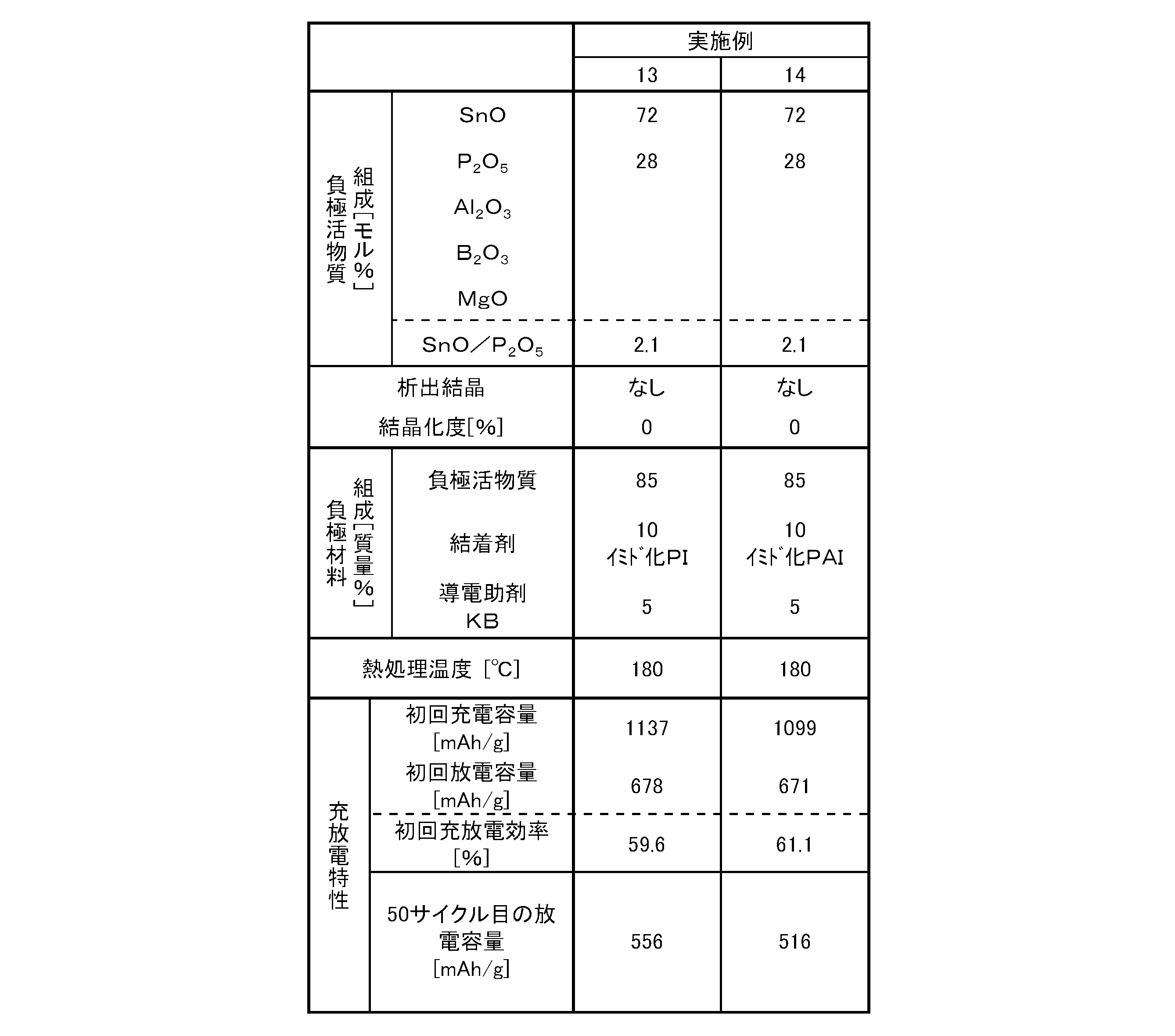
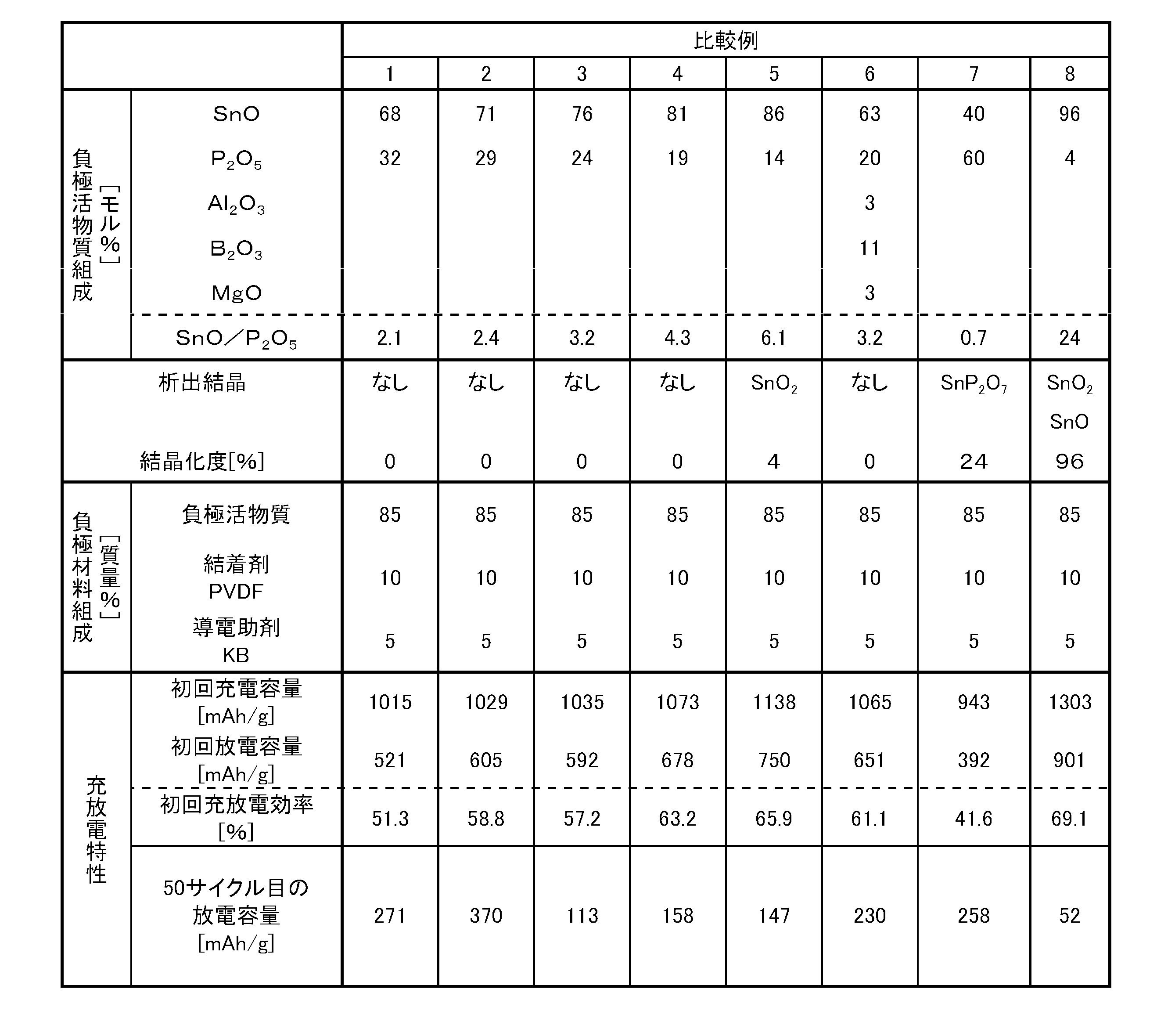
- the composite powder of tin and phosphorus (stannous pyrophosphate: Sn 2 P 2 O 7 ) is used as the main raw material so that the compositions shown in Tables 1 to 3 are used, and the raw material powder is made of various oxides, carbonate raw materials, etc. Was prepared.
- the raw material powder was put into a quartz crucible and melted at 950 ° C. for 40 minutes in a nitrogen atmosphere using an electric furnace to be vitrified.
- the molten glass was poured out between a pair of rotating rollers, and molded while being rapidly cooled by the rotating roller to obtain a film-like glass having a thickness of 0.1 to 2 mm.
- This film-like glass was placed in a ball mill containing zirconia balls having a diameter of 2 to 3 cm, pulverized at 100 rpm for 3 hours, and then passed through a resin sieve having an opening of 120 ⁇ m to obtain a coarse glass powder having an average particle size of 8 to 15 ⁇ m.
- this coarse powder glass was put into a ball mill containing zirconia balls of ⁇ 5 mm, ethanol was added and pulverized at 40 rpm for 5 hours, and then dried at 200 ° C. for 4 hours to obtain glass powder having an average particle diameter of 2 to 5 ⁇ m (negative electrode Active material).
- the structure was identified by measuring powder X-ray diffraction for each sample.
- the negative electrode active materials of Examples 1 to 9, 12 to 14 and Comparative Examples 1 to 4 and 6 were amorphous, and no crystals were detected.
- the negative electrode active materials of Examples 10 and 11 and Comparative Examples 5 and 7 were almost amorphous, but some crystals were detected.
- the negative electrode active material of Comparative Example 8 had a crystallinity of almost 100%.
- PI imidized polyimide resin in Example 13
- imidized PAI imidized polyamideimide resin in Example 14
- KB was used as a conductive additive
- PVDF polyvinylidene fluoride
- the obtained slurry was coated on a 20 ⁇ m thick copper foil as a negative electrode current collector, dried with a dryer at 70 ° C., and then passed between a pair of rotating rollers.
- the electrode sheet was punched to a diameter of 11 mm with an electrode punching machine and dried (imidated) simultaneously with drying in a reduced pressure for 10 hours at the thermosetting temperature shown in Table 1 to obtain a circular working electrode ( Negative electrode for non-aqueous secondary battery) was obtained.
- the electrode sheet was punched to a diameter of 11 mm with an electrode punching machine and dried in a reduced pressure for 3 hours at the heat treatment temperature shown in Table 2 to obtain a circular working electrode (negative electrode for non-aqueous secondary battery) Got.
- the electrode sheet was punched to a diameter of 11 mm with an electrode punching machine and dried under reduced pressure at 140 ° C. for 4 hours to obtain a circular working electrode.
- Charging / discharging test Charging (occlusion of lithium ions in the negative electrode material) performed CC (constant current) charging from 2 V to 0 V at 0.2 mA.
- discharge release of lithium ions from the negative electrode material was discharged from 0 V to 2 V at a constant current of 0.2 mA. This charge / discharge cycle was repeated.
- Tables 1 and 2 show the results of the initial charge / discharge characteristics when the charge / discharge test was performed and the cycle characteristics when the battery was repeatedly charged / discharged, with respect to the batteries using the negative electrode materials of Examples and Comparative Examples.
- the initial discharge capacity of the batteries using the negative electrode materials of Examples 1 to 14 was 670 mAh / g or more, and the discharge capacity at the 50th cycle was good at 396 mAh / g or more.
- the batteries using the negative electrode materials of Comparative Examples 1 to 8 had an initial discharge capacity of 392 mAh / g or more, but the discharge capacity at the 50th cycle was significantly reduced to 370 mAh / g or less.
Landscapes
- Chemical & Material Sciences (AREA)
- Chemical Kinetics & Catalysis (AREA)
- Electrochemistry (AREA)
- General Chemical & Material Sciences (AREA)
- Engineering & Computer Science (AREA)
- Manufacturing & Machinery (AREA)
- Composite Materials (AREA)
- Inorganic Chemistry (AREA)
- Materials Engineering (AREA)
- Battery Electrode And Active Subsutance (AREA)
- Electric Double-Layer Capacitors Or The Like (AREA)
- Secondary Cells (AREA)
Abstract
Description
Sn+yLi++ye-←→LiySn ・・・(2)
表1~3に実施例1~14および比較例1~8を示す。各負極活物質は以下のようにして作製した。
上記で得られた負極活物質に対し、表1~3に示す組成となるように導電助剤と結着剤を秤量し、N-メチルピロリドン(NMP)に分散した後、自転・公転ミキサーで十分に撹拌してスラリー化した。ここで、表1および2に示す実施例1~14の負極材料には導電助剤にケッチャンブラック(以下、「KB」と略す)を用い、結着剤に実施例1~12ではポリイミド樹脂(以下、「PI」と略す)、実施例13ではイミド化されたポリイミド樹脂(以下、「イミド化PI」と略す)、実施例14ではイミド化されたポリアミドイミド樹脂(以下、「イミド化PAI」と略す)をそれぞれ用いた。表3に示す比較例1~8は導電助剤にKB、結着剤に熱可塑性樹脂であるポリフッ化ビニリデン(以下、「PVDF」と略す)を用いた。
コインセルの下蓋に、上記作用極を銅箔面を下に向けて載置し、その上に60℃で8時間減圧乾燥した直径16mmのポリプロピレン多孔質膜(ヘキストセラニーズ社製 セルガード#2400)からなるセパレータ、および対極である金属リチウムを積層し、試験電池を作製した。電解液としては、1M LiPF6溶液/EC:DEC=1:1(EC=エチレンカーボネート、DEC=ジエチルカーボネート)を用いた。なお試験電池の組み立ては露点温度-60℃以下の環境で行った。
充電(負極材料へのリチウムイオンの吸蔵)は、0.2mAで2Vから0VまでCC(定電流)充電を行った。次に、放電(負極材料からのリチウムイオンの放出)は、0.2mAの定電流で0Vから2Vまで放電させた。この充放電サイクルを繰り返し行った。

Claims (10)
- 少なくともSnOとP2O5を含有する化合物からなる負極活物質と、熱硬化性樹脂からなる結着剤を含有することを特徴とする蓄電デバイス用負極材料。
- さらに、導電助剤を含有することを特徴とする請求項1に記載の蓄電デバイス用負極材料。
- 質量%で、負極活物質 55~90%、結着剤 5~30%、導電助剤 3~20%を含有することを特徴とする請求項2に記載の蓄電デバイス用負極材料。
- 負極活物質が、モル%で、SnO 45~95%、P2O5 5~55%の組成を含有することを特徴とする請求項1~3のいずれかに記載の蓄電デバイス用負極材料。
- 負極活物質が実質的に非晶質であることを特徴とする請求項1~4のいずれかに記載の蓄電デバイス用負極材料。
- 熱硬化性樹脂がポリイミド樹脂であることを特徴とする請求項1~5のいずれかに記載の蓄電デバイス用負極材料。
- 導電助剤が高導電性カーボンブラックであることを特徴とする請求項1~6のいずれかに記載の蓄電デバイス用負極材料。
- 蓄電デバイスが、非水二次電池であることを特徴とする請求項1~7のいずれかに記載の蓄電デバイス用負極材料。
- 請求項1~8のいずれかに記載の蓄電デバイス用負極材料が集電体表面に塗布されてなる蓄電デバイス用負極。
- 請求項9に記載の蓄電デバイス用負極を製造する方法であって、蓄電デバイス用負極材料を集電体表面に塗布した後、減圧下にて150~400℃で熱処理することを特徴とする蓄電デバイス用負極の製造方法。
Priority Applications (2)
| Application Number | Priority Date | Filing Date | Title |
|---|---|---|---|
| US13/510,338 US9017870B2 (en) | 2009-11-25 | 2010-11-19 | Negative electrode material for an electrical storage device, and negative electrode for an electrical storage device using the same |
| CN2010800529693A CN102640328A (zh) | 2009-11-25 | 2010-11-19 | 蓄电装置用负极材料及使用该负极材料的蓄电装置用负极 |
Applications Claiming Priority (2)
| Application Number | Priority Date | Filing Date | Title |
|---|---|---|---|
| JP2009267373 | 2009-11-25 | ||
| JP2009-267373 | 2009-11-25 |
Publications (1)
| Publication Number | Publication Date |
|---|---|
| WO2011065307A1 true WO2011065307A1 (ja) | 2011-06-03 |
Family
ID=44066412
Family Applications (1)
| Application Number | Title | Priority Date | Filing Date |
|---|---|---|---|
| PCT/JP2010/070694 Ceased WO2011065307A1 (ja) | 2009-11-25 | 2010-11-19 | 蓄電デバイス用負極材料及びそれを用いた蓄電デバイス用負極 |
Country Status (5)
| Country | Link |
|---|---|
| US (1) | US9017870B2 (ja) |
| JP (1) | JP5663808B2 (ja) |
| KR (1) | KR20120094018A (ja) |
| CN (1) | CN102640328A (ja) |
| WO (1) | WO2011065307A1 (ja) |
Cited By (1)
| Publication number | Priority date | Publication date | Assignee | Title |
|---|---|---|---|---|
| US20130077206A1 (en) * | 2011-09-23 | 2013-03-28 | Kishor Purushottam Gadkaree | High voltage electro-chemical double layer capacitor |
Families Citing this family (2)
| Publication number | Priority date | Publication date | Assignee | Title |
|---|---|---|---|---|
| WO2009111194A1 (en) * | 2008-02-29 | 2009-09-11 | Arkema Inc. | High efficiency photovoltaic modules |
| CN104559066B (zh) * | 2013-10-28 | 2018-01-09 | 中国石油化工股份有限公司 | 热熔法预浸料用中温固化环氧树脂组合物及其制备方法 |
Citations (7)
| Publication number | Priority date | Publication date | Assignee | Title |
|---|---|---|---|---|
| JPH08236158A (ja) * | 1995-02-27 | 1996-09-13 | Fuji Photo Film Co Ltd | 非水二次電池 |
| JPH08298121A (ja) * | 1995-04-25 | 1996-11-12 | Fuji Photo Film Co Ltd | 非水二次電池 |
| JP2002231209A (ja) * | 2001-01-31 | 2002-08-16 | Matsushita Electric Ind Co Ltd | 非水電解液二次電池 |
| JP2004349016A (ja) * | 2003-05-20 | 2004-12-09 | Matsushita Electric Ind Co Ltd | 非水電解質二次電池の充放電方法 |
| JP2008153117A (ja) * | 2006-12-19 | 2008-07-03 | Nec Tokin Corp | 非水電解質二次電池用負極およびそれを用いた非水電解質二次電池 |
| JP2009164104A (ja) * | 2007-09-06 | 2009-07-23 | Canon Inc | 負極用電極材料、その製造方法ならびに該材料を用いた電極構造体及び蓄電デバイス |
| JP2009266473A (ja) * | 2008-04-23 | 2009-11-12 | Sony Corp | 負極および二次電池 |
Family Cites Families (6)
| Publication number | Priority date | Publication date | Assignee | Title |
|---|---|---|---|---|
| USRE35818E (en) | 1992-10-01 | 1998-06-02 | Seiko Instruments Inc. | Non-aqueous electrolyte secondary battery and method of producing the same |
| JP2887632B2 (ja) | 1993-03-22 | 1999-04-26 | セイコーインスツルメンツ株式会社 | 非水電解質二次電池 |
| US5618640A (en) | 1993-10-22 | 1997-04-08 | Fuji Photo Film Co., Ltd. | Nonaqueous secondary battery |
| JP3498380B2 (ja) | 1994-02-28 | 2004-02-16 | 宇部興産株式会社 | 非水二次電池 |
| US5707756A (en) * | 1994-11-29 | 1998-01-13 | Fuji Photo Film Co., Ltd. | Non-aqueous secondary battery |
| JP3890671B2 (ja) | 1997-04-22 | 2007-03-07 | 宇部興産株式会社 | 非水電解質二次電池用負極材料の製造方法およびこれを用いた負極と電池 |
-
2010
- 2010-11-19 CN CN2010800529693A patent/CN102640328A/zh active Pending
- 2010-11-19 JP JP2010259032A patent/JP5663808B2/ja active Active
- 2010-11-19 KR KR1020127014870A patent/KR20120094018A/ko not_active Withdrawn
- 2010-11-19 WO PCT/JP2010/070694 patent/WO2011065307A1/ja not_active Ceased
- 2010-11-19 US US13/510,338 patent/US9017870B2/en active Active
Patent Citations (7)
| Publication number | Priority date | Publication date | Assignee | Title |
|---|---|---|---|---|
| JPH08236158A (ja) * | 1995-02-27 | 1996-09-13 | Fuji Photo Film Co Ltd | 非水二次電池 |
| JPH08298121A (ja) * | 1995-04-25 | 1996-11-12 | Fuji Photo Film Co Ltd | 非水二次電池 |
| JP2002231209A (ja) * | 2001-01-31 | 2002-08-16 | Matsushita Electric Ind Co Ltd | 非水電解液二次電池 |
| JP2004349016A (ja) * | 2003-05-20 | 2004-12-09 | Matsushita Electric Ind Co Ltd | 非水電解質二次電池の充放電方法 |
| JP2008153117A (ja) * | 2006-12-19 | 2008-07-03 | Nec Tokin Corp | 非水電解質二次電池用負極およびそれを用いた非水電解質二次電池 |
| JP2009164104A (ja) * | 2007-09-06 | 2009-07-23 | Canon Inc | 負極用電極材料、その製造方法ならびに該材料を用いた電極構造体及び蓄電デバイス |
| JP2009266473A (ja) * | 2008-04-23 | 2009-11-12 | Sony Corp | 負極および二次電池 |
Cited By (3)
| Publication number | Priority date | Publication date | Assignee | Title |
|---|---|---|---|---|
| US20130077206A1 (en) * | 2011-09-23 | 2013-03-28 | Kishor Purushottam Gadkaree | High voltage electro-chemical double layer capacitor |
| CN103828002A (zh) * | 2011-09-23 | 2014-05-28 | 康宁股份有限公司 | 高压电化学双电层电容器 |
| US8842417B2 (en) * | 2011-09-23 | 2014-09-23 | Corning Incorporated | High voltage electro-chemical double layer capacitor |
Also Published As
| Publication number | Publication date |
|---|---|
| US20120276448A1 (en) | 2012-11-01 |
| KR20120094018A (ko) | 2012-08-23 |
| US9017870B2 (en) | 2015-04-28 |
| JP2011134704A (ja) | 2011-07-07 |
| CN102640328A (zh) | 2012-08-15 |
| JP5663808B2 (ja) | 2015-02-04 |
Similar Documents
| Publication | Publication Date | Title |
|---|---|---|
| Yang et al. | Synthesis and electrochemical performance of Li2FeSiO4/C/carbon nanosphere composite cathode materials for lithium ion batteries | |
| US9397333B2 (en) | Method for manufacturing carbon-sulfur composite, carbon-sulfur composite manufactured thereby, and lithium-sulfur battery | |
| JP5645056B2 (ja) | 蓄電デバイス用負極活物質ならびにこれを用いた蓄電デバイス用負極材料および蓄電デバイス用負極 | |
| JP6288257B2 (ja) | ナノシリコン材料とその製造方法及び二次電池の負極 | |
| WO2015030053A1 (ja) | 全固体電池および電極活物質の製造方法 | |
| WO2012063745A1 (ja) | 蓄電デバイス用負極材料およびそれを用いた蓄電デバイス用負極 | |
| JP2012182115A (ja) | 蓄電デバイス用負極活物質の製造方法 | |
| JP6300176B2 (ja) | ナトリウム二次電池用負極活物質 | |
| JP2025540957A (ja) | 複合正極活物質、それを採用した正極とリチウム電池及びその製造方法 | |
| JP7447396B2 (ja) | アルカリ金属イオン電池 | |
| JP5601615B2 (ja) | 蓄電デバイス用負極活物質及びその製造方法 | |
| CN102549816B (zh) | 蓄电器件用负极活性物质及其制造方法 | |
| JP5663808B2 (ja) | 蓄電デバイス用負極材料及びそれを用いた蓄電デバイス用負極 | |
| JP6273868B2 (ja) | 蓄電デバイス用負極活物質およびその製造方法 | |
| JP2013191296A (ja) | 蓄電デバイス | |
| KR20070063185A (ko) | 이차 전지용 전극활물질 | |
| JP2017016773A (ja) | リチウムイオン二次電池負極及び二次電池 | |
| JP6175906B2 (ja) | 蓄電デバイス用負極活物質およびその製造方法 | |
| JP2012204266A (ja) | 蓄電デバイス用負極活物質、ならびに、それを用いた蓄電デバイス用負極材料および蓄電デバイス用負極 | |
| JP2013080664A (ja) | 蓄電デバイス | |
| JP6241130B2 (ja) | 蓄電デバイス用負極活物質 | |
| JP5621868B2 (ja) | リチウムイオン二次電池 | |
| CN103730647B (zh) | 斜方锰矿石材料及其制备方法、负极和锂电池 | |
| WO2011049158A1 (ja) | 蓄電デバイス用負極活物質及びその製造方法 | |
| WO2013062037A1 (ja) | 酸化物材料の製造方法 |
Legal Events
| Date | Code | Title | Description |
|---|---|---|---|
| WWE | Wipo information: entry into national phase |
Ref document number: 201080052969.3 Country of ref document: CN |
|
| 121 | Ep: the epo has been informed by wipo that ep was designated in this application |
Ref document number: 10833153 Country of ref document: EP Kind code of ref document: A1 |
|
| NENP | Non-entry into the national phase |
Ref country code: DE |
|
| ENP | Entry into the national phase |
Ref document number: 20127014870 Country of ref document: KR Kind code of ref document: A |
|
| WWE | Wipo information: entry into national phase |
Ref document number: 13510338 Country of ref document: US |
|
| 122 | Ep: pct application non-entry in european phase |
Ref document number: 10833153 Country of ref document: EP Kind code of ref document: A1 |