WO2011065222A1 - 窒素化合物含有酸性液の処理装置および処理方法 - Google Patents
窒素化合物含有酸性液の処理装置および処理方法 Download PDFInfo
- Publication number
- WO2011065222A1 WO2011065222A1 PCT/JP2010/069932 JP2010069932W WO2011065222A1 WO 2011065222 A1 WO2011065222 A1 WO 2011065222A1 JP 2010069932 W JP2010069932 W JP 2010069932W WO 2011065222 A1 WO2011065222 A1 WO 2011065222A1
- Authority
- WO
- WIPO (PCT)
- Prior art keywords
- chamber
- nitrogen compound
- concentration
- solution
- neutralized
- Prior art date
Links
- 229910017464 nitrogen compound Inorganic materials 0.000 title claims abstract description 90
- 150000002830 nitrogen compounds Chemical class 0.000 title claims abstract description 90
- 239000003929 acidic solution Substances 0.000 title claims abstract description 28
- 238000000034 method Methods 0.000 title claims description 22
- XLYOFNOQVPJJNP-UHFFFAOYSA-N water Substances O XLYOFNOQVPJJNP-UHFFFAOYSA-N 0.000 claims abstract description 153
- 239000000243 solution Substances 0.000 claims abstract description 58
- 239000012670 alkaline solution Substances 0.000 claims abstract description 50
- 239000007788 liquid Substances 0.000 claims description 128
- 238000009296 electrodeionization Methods 0.000 claims description 72
- 238000011033 desalting Methods 0.000 claims description 58
- 238000000909 electrodialysis Methods 0.000 claims description 42
- 230000002378 acidificating effect Effects 0.000 claims description 40
- 239000003011 anion exchange membrane Substances 0.000 claims description 32
- 239000000126 substance Substances 0.000 claims description 13
- 238000004821 distillation Methods 0.000 claims description 12
- 230000003472 neutralizing effect Effects 0.000 claims description 9
- 150000003839 salts Chemical class 0.000 claims description 8
- -1 amine compound Chemical class 0.000 claims description 7
- 239000007800 oxidant agent Substances 0.000 claims description 7
- 230000008569 process Effects 0.000 claims description 6
- 239000000463 material Substances 0.000 claims description 5
- 239000012476 oxidizable substance Substances 0.000 claims 1
- 238000009938 salting Methods 0.000 claims 1
- 238000006386 neutralization reaction Methods 0.000 abstract description 77
- HZAXFHJVJLSVMW-UHFFFAOYSA-N 2-Aminoethan-1-ol Chemical compound NCCO HZAXFHJVJLSVMW-UHFFFAOYSA-N 0.000 abstract description 39
- 238000000502 dialysis Methods 0.000 abstract description 39
- 230000008929 regeneration Effects 0.000 abstract description 24
- 238000011069 regeneration method Methods 0.000 abstract description 24
- VEXZGXHMUGYJMC-UHFFFAOYSA-N Hydrochloric acid Chemical compound Cl VEXZGXHMUGYJMC-UHFFFAOYSA-N 0.000 abstract description 17
- 238000005349 anion exchange Methods 0.000 abstract description 10
- 238000010612 desalination reaction Methods 0.000 abstract description 9
- 239000002351 wastewater Substances 0.000 abstract description 2
- 238000002242 deionisation method Methods 0.000 abstract 1
- 239000002699 waste material Substances 0.000 description 52
- HEMHJVSKTPXQMS-UHFFFAOYSA-M Sodium hydroxide Chemical compound [OH-].[Na+] HEMHJVSKTPXQMS-UHFFFAOYSA-M 0.000 description 48
- 238000010790 dilution Methods 0.000 description 37
- 239000012895 dilution Substances 0.000 description 37
- 150000002500 ions Chemical class 0.000 description 33
- 239000012528 membrane Substances 0.000 description 29
- NWUYHJFMYQTDRP-UHFFFAOYSA-N 1,2-bis(ethenyl)benzene;1-ethenyl-2-ethylbenzene;styrene Chemical compound C=CC1=CC=CC=C1.CCC1=CC=CC=C1C=C.C=CC1=CC=CC=C1C=C NWUYHJFMYQTDRP-UHFFFAOYSA-N 0.000 description 26
- 239000002253 acid Substances 0.000 description 26
- 239000003513 alkali Substances 0.000 description 23
- 150000001768 cations Chemical class 0.000 description 21
- 239000003957 anion exchange resin Substances 0.000 description 16
- 239000003729 cation exchange resin Substances 0.000 description 15
- 239000012141 concentrate Substances 0.000 description 15
- 150000001412 amines Chemical class 0.000 description 13
- 238000012545 processing Methods 0.000 description 12
- 239000003456 ion exchange resin Substances 0.000 description 11
- 229920003303 ion-exchange polymer Polymers 0.000 description 11
- 239000007864 aqueous solution Substances 0.000 description 10
- 238000005341 cation exchange Methods 0.000 description 10
- 230000000052 comparative effect Effects 0.000 description 9
- 238000005115 demineralization Methods 0.000 description 9
- 230000002328 demineralizing effect Effects 0.000 description 9
- QAOWNCQODCNURD-UHFFFAOYSA-N Sulfuric acid Chemical compound OS(O)(=O)=O QAOWNCQODCNURD-UHFFFAOYSA-N 0.000 description 8
- 150000001450 anions Chemical class 0.000 description 8
- 239000003054 catalyst Substances 0.000 description 7
- 238000010586 diagram Methods 0.000 description 7
- 230000033001 locomotion Effects 0.000 description 7
- 230000007797 corrosion Effects 0.000 description 6
- 238000005260 corrosion Methods 0.000 description 6
- 238000007254 oxidation reaction Methods 0.000 description 6
- 238000011045 prefiltration Methods 0.000 description 6
- 238000001125 extrusion Methods 0.000 description 5
- QWPPOHNGKGFGJK-UHFFFAOYSA-N hypochlorous acid Chemical compound ClO QWPPOHNGKGFGJK-UHFFFAOYSA-N 0.000 description 5
- 239000002440 industrial waste Substances 0.000 description 5
- 239000011347 resin Substances 0.000 description 5
- 229920005989 resin Polymers 0.000 description 5
- 229910001415 sodium ion Inorganic materials 0.000 description 5
- QGZKDVFQNNGYKY-UHFFFAOYSA-N Ammonia Chemical compound N QGZKDVFQNNGYKY-UHFFFAOYSA-N 0.000 description 4
- OKTJSMMVPCPJKN-UHFFFAOYSA-N Carbon Chemical compound [C] OKTJSMMVPCPJKN-UHFFFAOYSA-N 0.000 description 4
- 230000000694 effects Effects 0.000 description 4
- 239000003014 ion exchange membrane Substances 0.000 description 4
- 230000001590 oxidative effect Effects 0.000 description 4
- 238000010248 power generation Methods 0.000 description 4
- 239000011734 sodium Substances 0.000 description 4
- 238000012546 transfer Methods 0.000 description 4
- 229910021642 ultra pure water Inorganic materials 0.000 description 4
- 239000012498 ultrapure water Substances 0.000 description 4
- WMFOQBRAJBCJND-UHFFFAOYSA-M Lithium hydroxide Chemical compound [Li+].[OH-] WMFOQBRAJBCJND-UHFFFAOYSA-M 0.000 description 3
- KWYUFKZDYYNOTN-UHFFFAOYSA-M Potassium hydroxide Chemical compound [OH-].[K+] KWYUFKZDYYNOTN-UHFFFAOYSA-M 0.000 description 3
- 150000007513 acids Chemical class 0.000 description 3
- 238000003421 catalytic decomposition reaction Methods 0.000 description 3
- 230000003197 catalytic effect Effects 0.000 description 3
- 150000001875 compounds Chemical class 0.000 description 3
- 230000006866 deterioration Effects 0.000 description 3
- 238000005516 engineering process Methods 0.000 description 3
- 238000002474 experimental method Methods 0.000 description 3
- 238000010438 heat treatment Methods 0.000 description 3
- 238000005342 ion exchange Methods 0.000 description 3
- 230000007935 neutral effect Effects 0.000 description 3
- 230000003647 oxidation Effects 0.000 description 3
- 239000011148 porous material Substances 0.000 description 3
- 230000009467 reduction Effects 0.000 description 3
- 238000001179 sorption measurement Methods 0.000 description 3
- 238000005979 thermal decomposition reaction Methods 0.000 description 3
- IJGRMHOSHXDMSA-UHFFFAOYSA-N Atomic nitrogen Chemical compound N#N IJGRMHOSHXDMSA-UHFFFAOYSA-N 0.000 description 2
- OAKJQQAXSVQMHS-UHFFFAOYSA-N Hydrazine Chemical compound NN OAKJQQAXSVQMHS-UHFFFAOYSA-N 0.000 description 2
- YNAVUWVOSKDBBP-UHFFFAOYSA-N Morpholine Chemical compound C1COCCN1 YNAVUWVOSKDBBP-UHFFFAOYSA-N 0.000 description 2
- CDBYLPFSWZWCQE-UHFFFAOYSA-L Sodium Carbonate Chemical compound [Na+].[Na+].[O-]C([O-])=O CDBYLPFSWZWCQE-UHFFFAOYSA-L 0.000 description 2
- 229910021529 ammonia Inorganic materials 0.000 description 2
- 238000002048 anodisation reaction Methods 0.000 description 2
- 125000002091 cationic group Chemical group 0.000 description 2
- 239000003795 chemical substances by application Substances 0.000 description 2
- 238000002485 combustion reaction Methods 0.000 description 2
- 239000004020 conductor Substances 0.000 description 2
- 238000000354 decomposition reaction Methods 0.000 description 2
- 238000009792 diffusion process Methods 0.000 description 2
- 238000011049 filling Methods 0.000 description 2
- 238000002156 mixing Methods 0.000 description 2
- 239000008239 natural water Substances 0.000 description 2
- 238000010525 oxidative degradation reaction Methods 0.000 description 2
- 239000012466 permeate Substances 0.000 description 2
- 229920001343 polytetrafluoroethylene Polymers 0.000 description 2
- 239000004810 polytetrafluoroethylene Substances 0.000 description 2
- 238000000926 separation method Methods 0.000 description 2
- 230000009897 systematic effect Effects 0.000 description 2
- 230000001052 transient effect Effects 0.000 description 2
- 238000009279 wet oxidation reaction Methods 0.000 description 2
- JPVYNHNXODAKFH-UHFFFAOYSA-N Cu2+ Chemical compound [Cu+2] JPVYNHNXODAKFH-UHFFFAOYSA-N 0.000 description 1
- 241000220317 Rosa Species 0.000 description 1
- 241000009298 Trigla lyra Species 0.000 description 1
- 229910001413 alkali metal ion Inorganic materials 0.000 description 1
- 125000000129 anionic group Chemical group 0.000 description 1
- 238000007743 anodising Methods 0.000 description 1
- 229910017052 cobalt Inorganic materials 0.000 description 1
- 239000010941 cobalt Substances 0.000 description 1
- GUTLYIVDDKVIGB-UHFFFAOYSA-N cobalt atom Chemical compound [Co] GUTLYIVDDKVIGB-UHFFFAOYSA-N 0.000 description 1
- 229910001431 copper ion Inorganic materials 0.000 description 1
- 239000008367 deionised water Substances 0.000 description 1
- 229910021641 deionized water Inorganic materials 0.000 description 1
- 238000004090 dissolution Methods 0.000 description 1
- 230000005611 electricity Effects 0.000 description 1
- 238000005868 electrolysis reaction Methods 0.000 description 1
- 238000012851 eutrophication Methods 0.000 description 1
- 238000001704 evaporation Methods 0.000 description 1
- 239000000835 fiber Substances 0.000 description 1
- 239000010419 fine particle Substances 0.000 description 1
- 230000005484 gravity Effects 0.000 description 1
- IXCSERBJSXMMFS-UHFFFAOYSA-N hcl hcl Chemical compound Cl.Cl IXCSERBJSXMMFS-UHFFFAOYSA-N 0.000 description 1
- 230000008595 infiltration Effects 0.000 description 1
- 238000001764 infiltration Methods 0.000 description 1
- 239000003112 inhibitor Substances 0.000 description 1
- 230000002401 inhibitory effect Effects 0.000 description 1
- 230000009545 invasion Effects 0.000 description 1
- XEEYBQQBJWHFJM-UHFFFAOYSA-N iron Substances [Fe] XEEYBQQBJWHFJM-UHFFFAOYSA-N 0.000 description 1
- 229910052742 iron Inorganic materials 0.000 description 1
- 238000012423 maintenance Methods 0.000 description 1
- 230000007246 mechanism Effects 0.000 description 1
- 229910052751 metal Inorganic materials 0.000 description 1
- 239000002184 metal Substances 0.000 description 1
- 238000013508 migration Methods 0.000 description 1
- 230000005012 migration Effects 0.000 description 1
- 238000012986 modification Methods 0.000 description 1
- 230000004048 modification Effects 0.000 description 1
- 229910052757 nitrogen Inorganic materials 0.000 description 1
- 239000011368 organic material Substances 0.000 description 1
- 230000010287 polarization Effects 0.000 description 1
- 229910001414 potassium ion Inorganic materials 0.000 description 1
- 238000001556 precipitation Methods 0.000 description 1
- 238000003672 processing method Methods 0.000 description 1
- 239000000047 product Substances 0.000 description 1
- 230000001172 regenerating effect Effects 0.000 description 1
- 230000002040 relaxant effect Effects 0.000 description 1
- 229910000029 sodium carbonate Inorganic materials 0.000 description 1
- 229910001220 stainless steel Inorganic materials 0.000 description 1
- 239000011550 stock solution Substances 0.000 description 1
- 238000005292 vacuum distillation Methods 0.000 description 1
- 238000005406 washing Methods 0.000 description 1
- 238000004065 wastewater treatment Methods 0.000 description 1
Images


Classifications
-
- C—CHEMISTRY; METALLURGY
- C02—TREATMENT OF WATER, WASTE WATER, SEWAGE, OR SLUDGE
- C02F—TREATMENT OF WATER, WASTE WATER, SEWAGE, OR SLUDGE
- C02F1/00—Treatment of water, waste water, or sewage
- C02F1/46—Treatment of water, waste water, or sewage by electrochemical methods
- C02F1/469—Treatment of water, waste water, or sewage by electrochemical methods by electrochemical separation, e.g. by electro-osmosis, electrodialysis, electrophoresis
-
- B—PERFORMING OPERATIONS; TRANSPORTING
- B01—PHYSICAL OR CHEMICAL PROCESSES OR APPARATUS IN GENERAL
- B01D—SEPARATION
- B01D61/00—Processes of separation using semi-permeable membranes, e.g. dialysis, osmosis or ultrafiltration; Apparatus, accessories or auxiliary operations specially adapted therefor
- B01D61/42—Electrodialysis; Electro-osmosis ; Electro-ultrafiltration; Membrane capacitive deionization
- B01D61/422—Electrodialysis
- B01D61/423—Electrodialysis comprising multiple electrodialysis steps
-
- B—PERFORMING OPERATIONS; TRANSPORTING
- B01—PHYSICAL OR CHEMICAL PROCESSES OR APPARATUS IN GENERAL
- B01D—SEPARATION
- B01D61/00—Processes of separation using semi-permeable membranes, e.g. dialysis, osmosis or ultrafiltration; Apparatus, accessories or auxiliary operations specially adapted therefor
- B01D61/42—Electrodialysis; Electro-osmosis ; Electro-ultrafiltration; Membrane capacitive deionization
- B01D61/44—Ion-selective electrodialysis
- B01D61/46—Apparatus therefor
- B01D61/48—Apparatus therefor having one or more compartments filled with ion-exchange material, e.g. electrodeionisation
-
- B—PERFORMING OPERATIONS; TRANSPORTING
- B01—PHYSICAL OR CHEMICAL PROCESSES OR APPARATUS IN GENERAL
- B01D—SEPARATION
- B01D61/00—Processes of separation using semi-permeable membranes, e.g. dialysis, osmosis or ultrafiltration; Apparatus, accessories or auxiliary operations specially adapted therefor
- B01D61/58—Multistep processes
-
- G—PHYSICS
- G21—NUCLEAR PHYSICS; NUCLEAR ENGINEERING
- G21F—PROTECTION AGAINST X-RADIATION, GAMMA RADIATION, CORPUSCULAR RADIATION OR PARTICLE BOMBARDMENT; TREATING RADIOACTIVELY CONTAMINATED MATERIAL; DECONTAMINATION ARRANGEMENTS THEREFOR
- G21F9/00—Treating radioactively contaminated material; Decontamination arrangements therefor
- G21F9/04—Treating liquids
- G21F9/06—Processing
- G21F9/12—Processing by absorption; by adsorption; by ion-exchange
-
- G—PHYSICS
- G21—NUCLEAR PHYSICS; NUCLEAR ENGINEERING
- G21F—PROTECTION AGAINST X-RADIATION, GAMMA RADIATION, CORPUSCULAR RADIATION OR PARTICLE BOMBARDMENT; TREATING RADIOACTIVELY CONTAMINATED MATERIAL; DECONTAMINATION ARRANGEMENTS THEREFOR
- G21F9/00—Treating radioactively contaminated material; Decontamination arrangements therefor
- G21F9/04—Treating liquids
- G21F9/06—Processing
- G21F9/14—Processing by incineration; by calcination, e.g. desiccation
-
- B—PERFORMING OPERATIONS; TRANSPORTING
- B01—PHYSICAL OR CHEMICAL PROCESSES OR APPARATUS IN GENERAL
- B01D—SEPARATION
- B01D61/00—Processes of separation using semi-permeable membranes, e.g. dialysis, osmosis or ultrafiltration; Apparatus, accessories or auxiliary operations specially adapted therefor
- B01D61/24—Dialysis ; Membrane extraction
- B01D61/243—Dialysis
-
- C—CHEMISTRY; METALLURGY
- C02—TREATMENT OF WATER, WASTE WATER, SEWAGE, OR SLUDGE
- C02F—TREATMENT OF WATER, WASTE WATER, SEWAGE, OR SLUDGE
- C02F1/00—Treatment of water, waste water, or sewage
- C02F1/46—Treatment of water, waste water, or sewage by electrochemical methods
- C02F1/469—Treatment of water, waste water, or sewage by electrochemical methods by electrochemical separation, e.g. by electro-osmosis, electrodialysis, electrophoresis
- C02F1/4693—Treatment of water, waste water, or sewage by electrochemical methods by electrochemical separation, e.g. by electro-osmosis, electrodialysis, electrophoresis electrodialysis
- C02F1/4695—Treatment of water, waste water, or sewage by electrochemical methods by electrochemical separation, e.g. by electro-osmosis, electrodialysis, electrophoresis electrodialysis electrodeionisation
-
- C—CHEMISTRY; METALLURGY
- C02—TREATMENT OF WATER, WASTE WATER, SEWAGE, OR SLUDGE
- C02F—TREATMENT OF WATER, WASTE WATER, SEWAGE, OR SLUDGE
- C02F1/00—Treatment of water, waste water, or sewage
- C02F1/66—Treatment of water, waste water, or sewage by neutralisation; pH adjustment
-
- C—CHEMISTRY; METALLURGY
- C02—TREATMENT OF WATER, WASTE WATER, SEWAGE, OR SLUDGE
- C02F—TREATMENT OF WATER, WASTE WATER, SEWAGE, OR SLUDGE
- C02F2101/00—Nature of the contaminant
- C02F2101/30—Organic compounds
- C02F2101/38—Organic compounds containing nitrogen
-
- Y—GENERAL TAGGING OF NEW TECHNOLOGICAL DEVELOPMENTS; GENERAL TAGGING OF CROSS-SECTIONAL TECHNOLOGIES SPANNING OVER SEVERAL SECTIONS OF THE IPC; TECHNICAL SUBJECTS COVERED BY FORMER USPC CROSS-REFERENCE ART COLLECTIONS [XRACs] AND DIGESTS
- Y02—TECHNOLOGIES OR APPLICATIONS FOR MITIGATION OR ADAPTATION AGAINST CLIMATE CHANGE
- Y02A—TECHNOLOGIES FOR ADAPTATION TO CLIMATE CHANGE
- Y02A20/00—Water conservation; Efficient water supply; Efficient water use
- Y02A20/124—Water desalination
Definitions
- the present invention relates to a processing apparatus and method for efficiently separating and concentrating nitrogen compounds from an acidic liquid containing nitrogen compounds. Specifically, nitrogen compounds such as monoethanolamine are efficiently separated and concentrated from acidic liquids containing nitrogen compounds such as monoethanolamine-containing dilute hydrochloric acid waste liquid discharged during the regeneration of condensate demineralizers at nuclear power plants and thermal power plants.
- the present invention relates to a processing apparatus and a processing method.
- amines such as monoethanolamine (MEA) are used as an anticorrosive for steam generation lines.
- MEA monoethanolamine
- these amines are captured by the cation exchange resin of a condensate demineralizer (hereinafter sometimes referred to as “condemi”) provided in the line and regenerated when the condensate demineralizer is regenerated. It is contained in the waste liquid and discharged.
- the discharged amines become COD sources and eutrophication sources and contaminate rivers and lakes, so it is necessary to treat them.
- Patent Document 1 Conventionally, methods for treating monoethanolamine have been proposed by electrolysis (for example, Patent Document 1), biological treatment, activated carbon adsorption, or wet oxidation (catalytic decomposition, thermal decomposition).
- Patent Document 1 biological treatment, activated carbon adsorption, or wet oxidation (catalytic decomposition, thermal decomposition).
- problems such as being slow and excessive processing energy costs.
- Patent Documents 2 and 3 the amine compound is contact-oxidized using a noble metal-supported catalyst.
- the amine concentration is high, the deterioration rate of the catalyst is increased, and the replacement frequency of the catalyst is increased.
- the addition cost is enormous and uneconomical.
- heating energy cost also becomes a problem.
- Patent Document 4 the alkanolamine-containing acidic waste liquid is concentrated by distillation under reduced pressure without being neutralized.
- a concentrating device subjected to expensive anticorrosion treatment is required.
- ferritic stainless steel 25Cr can be used at a Cl ⁇ concentration of 5% or less, but exceeds 5%.
- Patent Document 5 Cl electrodialysis treatment using an anion-exchange membrane - After removal of the containing substances other than monoethanolamine and decomposed with wet catalyst treatment, but then have to recover monoethanolamine
- the cost of electrodialysis and the cost of catalyst treatment are enormous, which is uneconomical.
- the waste liquid from the regeneration of the condemi has the following problems due to the coexistence of a large amount of hydrochloric acid used for the regeneration of the ion exchange resin. That is, H + ions and other cation components (monoethanolamine, ammonia, hydrazine, etc.) are overwhelmed by the amount of movement of H + ions, even if they are equivalent as equivalents, because of their molar electrical conductivity.
- the molar conductivity ⁇ ⁇ at infinite dilution in an aqueous solution at 25 ° C. is H + : 349.8 S ⁇ cm 2 / mol, NH 4 + : 73.5 S ⁇ cm 2 / mol). Therefore, in the treatment of this waste condensate regeneration liquid, even if only electrodialysis is used, power is consumed not only for the movement of H + ions, but the energy cost is excessive and extremely inefficient.
- Patent Document 6 electrodialysis using an ion exchange membrane is used to remove and recover the acid from the waste acid.
- the membrane area is excessive, and in principle it is higher than the waste acid. Concentrated acid cannot be obtained, and the amount of dialysis waste liquid is larger than that of the stock solution due to infiltration of water, and there are limitations and disadvantages such as waste acid mixed into the dialysis waste liquid.
- Patent Document 7 in the treatment of the organic amine-containing recycled waste liquid, the waste liquid is heated to evaporate water, and the organic amine is vaporized from the obtained concentrated liquid.
- concentration of Cl 2 ⁇ ions becomes very high due to concentration, so there is a concern about the influence of corrosion on the apparatus.
- addition of an alkali such as NaOH increases the salt concentration and increases the maintenance frequency due to the precipitation of the salt.
- JP-A-9-239371 Japanese Patent No. 3793952 Japanese Patent No. 3568298 Japanese Patent No. 3083504 JP 2005-66544 A JP 2007-7655 A JP-A-9-314128
- An object of the present invention is to provide an apparatus and method for efficiently and economically treating a nitrogen compound-containing acidic liquid such as a monoethanolamine-containing dilute hydrochloric acid waste liquid discharged during regeneration of a condensate.
- the present inventors can neutralize and desalinate the nitrogen compound-containing acidic solution by neutralization dialysis using an anion exchange membrane and an alkaline solution. It was found that the nitrogen compound can be efficiently separated and concentrated from the neutralized desalting solution.
- the present invention has been achieved on the basis of such knowledge, and the gist thereof is as follows.
- the nitrogen compound-containing acidic liquid treatment apparatus is an acidic liquid treatment apparatus containing a nitrogen compound, wherein the one chamber separated by the anion exchange membrane into one chamber and the other chamber is disposed in the one chamber.
- a neutralization and desalting apparatus that neutralizes and desalinates the acidic liquid by passing an alkaline solution through the other chamber and passing the alkaline solution through the other chamber, and neutralizing and desalting by the neutralizing and desalting apparatus.
- a concentration device for concentrating the nitrogen compound in the neutralized desalting treatment solution.
- the treatment apparatus for a nitrogen compound-containing acidic liquid according to a second aspect is characterized in that, in the first aspect, the concentration apparatus is any one of a distillation concentration apparatus, an electrodeionization apparatus, and an electrodialysis apparatus.
- the processing apparatus for a nitrogen compound-containing acidic liquid according to a third aspect is the processing apparatus according to the second aspect, wherein the concentrating device is an electrodeionization device or an electrodialysis device, and water is passed through the anode chamber of the electrodeionization device or electrodialysis device.
- the anodized water does not contain an oxidizing substance or a substance that becomes anodized by anodization.
- the apparatus for treating a nitrogen compound-containing acidic liquid according to a fourth aspect is characterized in that, in any one of the first to third aspects, the pH of the neutralized desalting treatment liquid is 5 to 9.
- the method for treating a nitrogen compound-containing acidic liquid according to a fifth aspect is a method for treating an acidic liquid containing a nitrogen compound, wherein the one chamber separated by the anion exchange membrane into one chamber and the other chamber is disposed in the one chamber.
- a neutralization and desalting step in which an acidic solution is passed and an alkaline solution is passed through the other chamber to neutralize and desalinate the acidic waste solution, and is neutralized and desalted in the neutralization and desalting step.
- a concentration step for concentrating the nitrogen compound in the neutralized desalting treatment liquid is a concentration step for concentrating the nitrogen compound in the neutralized desalting treatment liquid.
- the method for treating a nitrogen compound-containing acidic liquid according to a sixth aspect is characterized in that, in the fifth aspect, the concentration step is a concentration step using any one of a distillation concentration device, an electrodeionization device, and an electrodialysis device.
- the concentration step is a concentration step using an electrodeionization apparatus or an electrodialysis apparatus, and the anode chamber of the electrodeionization apparatus or electrodialysis apparatus is used. Further, it is characterized in that anodic water that does not contain an oxidizing substance or a substance that becomes anodized by anodization is passed.
- the method for treating a nitrogen compound-containing acidic liquid according to the eighth aspect is characterized in that, in any one of the fifth to seventh aspects, the neutralized desalting treatment liquid has a pH of 5 to 9.
- a nitrogen compound-containing acidic solution is first adjusted to a solution advantageous for the subsequent concentration treatment by neutralization and desalting treatment by neutralization dialysis treatment with an alkaline solution through an anion exchange membrane.
- the target ions to be moved on the cation side are mainly H +. It becomes an ion and is extremely inefficient, but neutralized to the extent that H + ions, which are an inhibitor of electrodialysis or electrodeionization, are sufficiently less than nitrogen compounds by neutralization dialysis using an anion exchange membrane.
- H + ions which are an inhibitor of electrodialysis or electrodeionization
- the nitrogen compound can be efficiently removed by the subsequent electrodeionization apparatus or electrodialysis apparatus.
- this neutralization dialysis removes not only H + ions but also Cl ⁇ ions, so that a solution with a small total ion dissolution amount can be obtained, and the subsequent concentration treatment becomes easy.
- the neutralization dialysis treatment using the anion exchange membrane according to the present invention is different from the method of neutralizing by directly adding an alkali to the nitrogen compound-containing acidic solution. Does not increase the total amount of ions.
- the concentration of the nitrogen compound in the neutralization demineralization treatment solution is preferably performed by a distillation concentration apparatus, an electrodeionization apparatus or an electrodialysis apparatus, and in particular, an electrodeionization apparatus or an electrodialysis apparatus is used.
- an electrodeionization apparatus is preferred in terms of concentration efficiency (second and sixth embodiments).
- the anode chamber of this electrodeionization apparatus or electrodialysis apparatus has an oxidizing substance or anodized and oxidized. It is preferable to pass water or an aqueous solution that does not contain a substance that becomes a property as anode water (third and seventh embodiments). That is, in the electrodeionization apparatus or the electrodialysis apparatus, Cl ⁇ enters the concentration chamber because the ions to be removed include not only the cation component but also the movement of the anion component.
- the anode chamber is separated from the adjacent desalting chamber or concentrating chamber by a cation exchange membrane (which may be a bipolar membrane), and when anodic water is circulated, it is mixed with the concentrated solution or the effluent of another chamber.
- a cation exchange membrane which may be a bipolar membrane
- the anode chamber, the oxidizing agent and Cl - is preferably a substance which becomes oxidizing been anodized as ions is prevented from flowing.
- the neutralization and desalting treatment of the nitrogen compound-containing acidic solution is preferably performed until the pH of the resulting neutralized desalting treatment solution is about 5 to 9, and the neutralization is performed until such pH is reached.
- the desalting treatment it is possible to obtain a neutralized desalting treatment solution from which the inhibitory substance in the nitrogen compound concentration treatment in the subsequent step has been sufficiently removed (fourth and eighth embodiments).
- the present invention is particularly effective for treating condensate regeneration waste liquid discharged from the condensate desalination process of nuclear power generation or thermal power generation, and is derived from the anticorrosive agent of condensate contained in the condensate regeneration waste liquid such as dilute hydrochloric acid waste liquid containing monoethanolamine.
- the MEA and NH 4 - components without causing problems of corrosion due to concentration of the acid component and salt component in the effluent can be removed efficiently concentrated.
- FIG. 1 is a system diagram showing a configuration of a neutralization dialysis apparatus employed in Example 1.
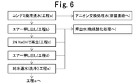
- FIG. 6 is a process diagram of anion exchange treatment in Comparative Example 2.
- FIG. 1 is a system diagram showing a configuration of a neutralization dialysis apparatus employed in Example 1.
- FIG. 6 is a process diagram of anion exchange treatment in Comparative Example 2.
- the nitrogen compound-containing acidic liquid to be treated in the present invention contains hydrochloric acid (HCl) as an acid, and the nitrogen compound-containing acidic liquid is neutralized with an aqueous sodium hydroxide solution as an alkaline solution.
- HCl hydrochloric acid
- the present invention will be described by exemplifying the case of desalting, but the acid contained in the nitrogen compound-containing acidic liquid to be treated in the present invention is not limited to hydrochloric acid, and may be other acids such as sulfuric acid. Good.
- the Cl ⁇ ion is an anion that forms a H + pair of an acid such as SO 4 2- ion
- Na + ions are cations that are pairs of alkali OH ⁇ such as K + ions.
- FIG. 1 is a system diagram showing an embodiment of an apparatus for treating a nitrogen compound-containing acidic solution of the present invention.
- This apparatus is an electrodeionization apparatus 4 that also serves as a raw water tank 1, a neutralization dialysis apparatus 2, and a relay tank.
- the to-be-processed liquid circulation tank 3, the electrodeionization apparatus 4, and the treated water tank 5 are mainly comprised.
- the acidic liquid containing a nitrogen compound to be treated in the present invention is not particularly limited, but for example, in a thermal power plant or a pressurized water nuclear power plant, an organic material such as monoethanolamine (MEA) or morpholine is used as an anticorrosive agent.
- MEA monoethanolamine
- morpholine is used as an anticorrosive agent.
- MEA monoethanolamine
- morpholine is used as an anticorrosive agent.
- MEA monoethanolamine
- morpholine is used as an anticorrosive agent.
- MEA monoethanolamine
- morpholine is used as an anticorrosive agent.
- regenerated the cation exchange resin used for the demineralization apparatus (condemi) of the condensate which added the amine compound is mentioned.
- the dehydrated acid waste solution contains organic amines that have been desorbed (accurately, acid salts of organic amines) and regenerated chemicals such as hydrochloric acid and sulfuric acid. In addition to acid, it contains trace amounts of copper ions, iron ions, and ammonia, which is a decomposition product of organic amines.
- the concentration of organic amine, the concentration of other water components and the pH of such a condensate regeneration acidic waste liquid vary depending on the type of the waste liquid, but the water quality is as follows, for example.
- a nitrogen compound-containing acidic solution (hereinafter sometimes referred to as “raw water”) is passed through one chamber separated by the anion exchange membrane into one chamber and the other chamber,
- the alkaline solution is passed through the other chamber to neutralize and desalinate the raw water.
- a neutralization dialysis device (diffusion dialysis device) 2 using an anion exchange membrane is preferably used as a device used for neutralization and desalting treatment of the raw water.
- FIG. 1 shows an example in which a neutralization dialysis device (diffusion dialysis device) 2 is used for neutralization and desalination treatment of raw water.
- the raw water in the raw water tank 1 is separated by a prefilter 11 by a pump P 1.
- the inside is introduced into the raw water chamber 22 of the neutralization dialysis apparatus 2 that is partitioned by the anion exchange membrane 21 into the raw water chamber 22 and the alkaline solution chamber 23.
- the pre-filter 11 is provided as necessary.
- the alkaline solution chamber 23, from the alkali solution tank 24, the alkali solution is introduced by a pump P 2.
- an aqueous solution of a soluble alkali compound such as sodium hydroxide (NaOH), potassium hydroxide, lithium hydroxide, sodium carbonate or the like can be used.
- the ratio of the resin used for the condemi is higher in the cation exchange resin than in the anion exchange resin, and the regeneration waste liquid of the anion exchange resin containing NaOH (hereinafter referred to as “condemi”) is higher than the regenerated acidic waste liquid of the cation exchange resin. It is sometimes called “recycled alkaline waste liquid”).
- separation is performed by using the difference in specific gravity of the anion exchange resin, the 16 weight% NaOH aqueous solution and the cation exchange resin using a 16 weight% NaOH aqueous solution.
- the alkaline waste liquid used for the separation is separately discharged.
- an alkaline waste liquid such as such a condemi regenerated alkaline waste liquid can be used as the alkaline solution.
- an alkaline waste liquid discharged from another facility may be used.
- the Cl ⁇ ion in the raw water introduced into the raw water chamber 22 passes through the anion exchange membrane 21 and moves to the alkaline solution chamber 23, and is desalted.
- the raw water is neutralized by OH ⁇ ions permeating through the anion exchange membrane 21 and moving to the raw water chamber 22.
- the effluent from the raw water chamber 22 is returned to the raw water tank 1 and the raw water is circulated.
- the effluent from the alkaline solution chamber 23 is also returned to the alkaline solution storage tank 24 and circulated.
- the anion exchange membrane 21 As the anion exchange membrane 21, a membrane excellent in acid resistance and alkali resistance is used. Further, the wetted surface of the neutralization dialysis apparatus 2 is also preferably made of a material having excellent corrosion resistance. For example, a lining made of a fluororesin such as polytetrafluoroethylene is preferable.
- the membrane surface flow rate on the alkaline solution chamber 23 side is preferably 0.1 cm / sec or more, for example, 1 to 8 cm / sec.
- the membrane surface flow rate is low, the moving speed of Cl - ions and OH - ions cannot be increased, and it takes a long time to obtain a desired neutralized desalting solution.
- excessively increasing the membrane surface flow velocity is not realistic in terms of the device configuration.
- an alkali solution having an alkali concentration higher than the acid concentration of the raw water and the alkali (N) value is 1 or more times, particularly about 2 to 4 times the acid concentration of the raw water.
- an alkaline solution having a concentration that is, for example, if the HCl concentration of the raw water is 1.2N, it is preferable to use an aqueous NaOH solution of 1.2 to 4.8N, especially about 2N as the alkaline solution. If the alkali concentration of the alkaline solution is low, efficient neutralization cannot be performed. However, it is preferable that the alkali solution has a concentration equal to or lower than the above in terms of its handleability.
- the waste solution such as the above-mentioned condemi regeneration alkaline waste solution
- the neutralization and desalting treatment is completed when the pH of the resulting neutralization desalting treatment solution (the effluent from the raw water chamber 22) becomes neutral, for example, about 5-9,
- the Japanese desalting solution is preferably subjected to the subsequent concentration treatment.
- a flow-through pH meter is installed in the outflow pipe of the raw water chamber 22 of the neutralization dialysis apparatus 2 to monitor the pH of the effluent in the raw water chamber 22, and this pH value reaches a predetermined value. Then, you may make it switch the liquid supply of the effluent of the raw
- the anion exchange membrane 21 permeates the cation component, and the cation component (for example, NaOH) from the alkaline solution 23 side to the raw water chamber 22 is obtained by the neutralization and desalting treatment as described above. of Na + ions) movement is, also, there is a movement of the cationic component derived from the nitrogen compound in an alkaline solution chamber 23 from the raw water chamber 22 side.
- the cation component for example, NaOH
- alkaline waste liquid contains Cl ⁇ ions dialyzed from the raw water, and neutralizes the raw water (to the raw water chamber). It is a weakly alkaline liquid whose pH has been lowered by dialysis of OH 2 ⁇ ions, and contains a slight amount of a nitrogen compound that has permeated the anion exchange membrane 21 from the raw water chamber 22. However, since the concentration of this nitrogen compound is low, this alkaline waste liquid can be discharged after neutralizing with an acid after decomposing the nitrogen compound with a catalytic oxidation apparatus or the like.
- the flow direction of the raw water in the raw water chamber 22 and the flow direction of the alkaline solution in the alkaline solution chamber 23 in the neutralization dialysis apparatus 2 may be cocurrent or countercurrent.
- the raw water and the alkaline solution can be passed in a transient manner, but generally, neutralization dialysis can be performed more sufficiently than in the transient manner. It is preferable to use circulating water as shown.
- raw water is introduced into the raw water tank 1 and the neutralized desalting treatment liquid returned from the raw water chamber 22 of the neutralization dialysis apparatus 2 is received by the raw water tank 1. It is preferable to take out a part of the liquid in the tank from the raw water tank 1 and use it for the next concentration treatment.
- the neutralization dialysis apparatus 2 has a raw water chamber 22 and an alkaline solution chamber 23 each formed by a single anion exchange membrane 21.
- a plurality of anion exchange membranes such as an alkali solution chamber / anion exchange membrane / raw water chamber / anion exchange membrane / alkali solution chamber / alkali exchange membrane / raw water chamber / anion exchange membrane / alkaline solution chamber.
- a plurality of raw water chambers and alkaline solution chambers may be alternately formed.
- the raw water is neutralized to neutral pH 5 to 9, for example, pH 6 to 8 (about pH 7) as described above.
- neutralization desalting solution was reduced to 30-50% of the ion concentration.
- nitrogen of neutralization desalination processing liquid The compound concentration is preferably 1000 mg / L or more, particularly about 5000 to 20000 mg / L.
- This concentration treatment can be performed by distillation concentration, or by using an electrodeionization apparatus or an electrodialysis apparatus.
- an electrodeionization apparatus or an electrodialysis apparatus can be preferably used, and in particular, an electrodeionization apparatus. Is preferably used.
- An electrodeionization apparatus or an electrodialysis apparatus includes an anode and a cathode, a dilution chamber and a concentration chamber partitioned by an ion-permeable diaphragm between the anode and the cathode, and applies a DC voltage between the anode and the cathode.
- ions derived from organic amines and nitrogen compounds such as NH 4 + and ions derived from acids and alkalis such as Na + and Cl ⁇ in the neutralized desalting solution introduced into the dilution chamber are ion-permeable.
- the permeation membrane is permeated and separated and collected in the concentration chamber.
- FIG. 1 shows an example in which the electrodeionization device 4 is used for concentration of nitrogen compounds, and the neutralization demineralization treatment liquid flowing out from the raw water chamber 22 of the neutralization dialysis device 2 is the liquid to be treated of the electrodeionization device 4.
- the pre-filter 12 is provided as necessary.
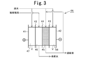
- FIGS. 2 and 3 are schematic cross-sectional views showing a schematic configuration of an example of an electrodeionization apparatus preferably used as a nitrogen compound concentrating device in the present invention.
- FIGS. are denoted by the same reference numerals.
- a plurality of anion exchange membranes (A membranes) 43 and cation exchange membranes (C membranes) 44 are alternately arranged between electrodes (anode 41, cathode 42) and a concentration chamber 45.
- the dilution chambers 46 are alternately formed.
- a cation exchange resin as a cation exchanger or an anion exchange resin as an anion exchanger and a cation exchange resin as a cation exchanger are mixed or filled in multiple layers.
- an ion exchanger you may use not only an ion exchange resin but an ion exchange fiber or a graft exchanger.
- the reason why only the cation exchanger or the combination of the cation exchanger and the anion exchanger is used is that the cation exchanger is present in the cell serving as the flow path in the dilution chamber 46. This is because the removal efficiency can be improved.
- the concentration chamber 45, the anode chamber 47, and the cathode chamber 48 are also filled with an anion exchange resin and a cation exchange resin as necessary.
- an electric conductor such as activated carbon or metal may be filled in the concentrating chamber 45, the anode chamber 47 and the cathode chamber 48.
- an electric conductor in order to stabilize the electric resistance value in the concentration chamber, the anode chamber, and the cathode chamber, the electric resistance of the liquid to be treated or the dilution water can be lowered, and the water passage pressure of the cell is not increased.
- materials that are susceptible to redox by directly touching the electrodes are not suitable.
- the anode chamber 47 is not filled with an anion exchange resin, and when filled, only the cation exchange resin is used. This is because anion exchange resins are susceptible to oxidative degradation.
- the neutralization and desalting treatment liquid that is the liquid to be treated in the electrodeionization apparatus 4 is introduced into the dilution chamber 46, and pure water is introduced into the concentration chamber 45, the anode chamber 47, and the cathode chamber 48. While the liquid to be treated flows through the dilution chamber 46, cation components such as organic amine, NH 4 + ions, and Na + ions in the solution permeate the cation exchange membrane (C membrane) 44 and enter the concentration chamber 45. Then, the cation component is concentrated in the concentration chamber 45. Similarly, Cl - anion components such as ions pass through the anion exchange membrane (A film) 43 moves to concentrating compartment 45, is concentrated in the concentrating compartment 45.
- cation components such as organic amine, NH 4 + ions, and Na + ions in the solution permeate the cation exchange membrane (C membrane) 44 and enter the concentration chamber 45. Then, the cation component is concentrated in the concentration chamber 45.
- Cl - anion components such
- the pump P 4 via the concentrated liquid circulation tank 49 is circulated to the inlet side of the concentrating compartment 45, the remainder being industrial waste receiving tank (industrial waste Receiving tank 13). Accordingly, pure water corresponding to the concentrated liquid discharged out of the system is introduced into the concentrating chamber 45 as makeup water.
- the amount of the circulating liquid circulated to the inlet side of the concentrating chamber 45 is appropriately determined according to the target concentration and processing efficiency. It is preferably about 1 to 20% of the total concentrated liquid discharged.
- Dilution water discharged from the dilution chamber 46 is for a cationic component and an anionic component in the neutralization desalting liquid is the liquid to be treated is separated off, is discharged by the pump P 5 through the treatment water tank 5, If necessary, it is used for wastewater treatment such as catalytic decomposition.
- this dilution water can also be used as the electrode water of an electrodeionization apparatus (or electrodialysis apparatus) and / or the pure water introduce
- the electrode chamber drainage discharged from the anode chamber 47 and the cathode chamber 48 is mixed with the anode water and the cathode water, and then subjected to an appropriate treatment as necessary to discharge and discharge or reuse the electrode chamber water supply.
- anode water may be pure water or an alkaline solution, for example, an alkaline aqueous solution such as NaOH of about 0.1 to 1N.
- the anode chamber 47 and the concentrating chamber 45 or dilution chamber 46 adjacent to the anode chamber 47 are separated by a cation exchange membrane (may be a piper membrane), and an oxidizing substance or a substance that becomes oxidizing by anodizing. Therefore, it is preferable that the anode water does not contain such a substance. Therefore, the anode chamber 47 does not contain such a substance.
- a cation exchange membrane may be a piper membrane
- FIG. 2 shows an example of an electrodeionization apparatus suitable as a concentrator in the present invention, and the electrodeionization apparatus used in the present invention is not limited to the illustrated one.
- the number and arrangement of the concentration chambers and dilution chambers are not particularly limited, and more concentration chambers and dilution chambers may be provided.
- the electrodeionization apparatus 4A provided one by one may be used. Even in this electrodeionization apparatus 4A, as in the electrodeionization apparatus 4 of FIG. 2, organic amine, NH 4 + ions, Na + ions, etc. in the neutralization demineralization treatment solution introduced into the dilution chamber 46 The cation component passes through the cation exchange membrane (C membrane) 44 and moves into the concentration chamber 45, and the cation component is concentrated in the concentration chamber 45. Similarly, Cl - anion components such as ions pass through the anion exchange membrane (A film) 43 moves to concentrating compartment 45, is concentrated in the concentrating compartment 45.
- the nitrogen compound concentrating device is not an electrodeionization device, but an electrodialysis device having the same configuration as the electrodeionization device except that the ion exchanger is not filled in the dilution chamber or the like. it can.
- concentration is performed by the same mechanism based on ion migration.
- the electrodeionization It is more efficient to use the device.
- an ion exchanger such as an ion exchange resin filled in the dilution chamber also serves as an adsorption site for ions to be removed, and the ions to be removed in a wide area. Since it can adsorb
- a distillation concentrator can also be used as the nitrogen compound concentrator. In this case, it is preferable to concentrate the neutralized desalting solution to such an extent that no salt is precipitated.
- the concentration of the nitrogen compound in the neutralization desalination treatment solution that flows into the dilution chamber of the electrodeionization device or the electrodialysis device Since the efficiency of the electrodeionization device or the electrodialysis device is reduced when the concentration is lowered, when the nitrogen compound concentration in the neutralization demineralization treatment solution becomes 1000 mg / L or less, the treatment is interrupted and the neutralization desalination treatment It is also possible to supply the liquid to a catalyst decomposition treatment device to decompose the nitrogen compound.
- the nitrogen compound concentrate (concentrated liquid discharged from the concentration chamber of the electrodeionization apparatus or electrodialysis apparatus) in which the nitrogen compound in the neutralization desalination treatment liquid is concentrated is treated by thermal decomposition or in-liquid combustion treatment. However, prior to that, if necessary, this concentrated solution may be further concentrated to increase the concentration of the nitrogen compound.
- the concentration means in this case is not particularly limited, but it is advantageous in terms of concentration efficiency to use a distillation concentration apparatus, particularly a vacuum distillation concentration apparatus.
- the degree of concentration of the concentrate is not particularly limited, but the concentration of the nitrogen compound in the concentrate used for thermal decomposition or in-liquid combustion treatment is 25% by weight or more, for example, about 40 to 95% by weight. It is preferable to concentrate.
- the nitrogen compound is monoethanolamine, if the concentration exceeds 70% by weight, the compound has a flash point. Therefore, the upper limit is preferably 70% by weight from the viewpoint of handling.
- the condensed water obtained by distillation concentration of the neutralized desalting solution or further concentration of the concentrated solution should be used as pure water to be introduced into the electrode chamber and / or the concentration chamber of the electrodeionization device or electrodialysis device. Can do.
- the dilution water (dilution water discharged from the dilution chamber of the electrodeionization apparatus or electrodialysis apparatus) obtained by concentrating the neutralization demineralization treatment solution with the electrodeionization apparatus or electrodialysis apparatus is The nitrogen compound and other ionic components in the salt treatment liquid are separated and removed. If necessary, the diluted water can be further treated by catalytic decomposition, and then neutralized and discharged.
- the neutralization and desalting treatment by the neutralization dialysis apparatus is performed by circulating the whole amount of the raw water and the alkaline solution, but the neutralization and desalting treatment in the present invention is not performed at all. It is not limited to the total amount circulating water treatment, it may be one that circulates only a part of the raw water or alkaline solution, or the whole amount may be transiently passed. .
- the entire amount of dilution water and concentrate is circulated, but only a part of the dilution water may be circulated, and the entire amount may be temporarily transferred. You may pass water. The same applies to electrode water.
- This electrodeionization apparatus As the electrodeionization apparatus, the one shown in FIG. 3 was used.
- This electrodeionization apparatus (MX manufactured by Siemens) includes an anion exchange membrane 43 and a cation exchange membrane 44 alternately as membranes, each having a membrane area of 0.75 dm 2 , a dilution chamber 46, a concentration chamber 45, and an anode chamber 47.
- the volume of the cathode chamber 48 is 60 mL each.
- anion exchange membrane 43 an anion exchange membrane “Neocepta AHA” manufactured by Astom Co., Ltd. was used, and as a cation exchange membrane 44, a cation exchange membrane “Neocepta CMB” manufactured by Astom Co., Ltd. was used.
- the dilution chamber 46 and the concentration chamber 45 were filled with an equal volume of cation exchange resin and anion exchange resin, respectively.
- the anode chamber 47 and the cathode chamber 48 were filled only with a cation exchange resin.
- the cation exchange resin “SK1B” manufactured by Mitsubishi Chemical Corporation was used as the cation exchange resin, and the anion exchange resin “SA10A” manufactured by Mitsubishi Chemical Corporation was used as the anion exchange resin.
- FIG. 4 is a water flow diagram of the used electrodeionization apparatus, and the same members as those in the electrodeionization apparatus shown in FIGS.
- the concentrate in the concentrate circulation tank 49 was introduced into the concentration chamber 45 by the pump P 4 , and then circulated through the concentrate circulation tank 49.
- the waste liquid is introduced into the dilution chamber 46 of the electrodeionization apparatus by the pump P 3, the dilution water from the dilution chamber 46, the liquid to be treated circulation tank Returned to No. 3 and circulated water.
- the anode water in the anode chamber 47 and the cathode water in the cathode chamber 48 were circulated through the anode water circulation tank 51 and the anode chamber 47, and the cathode water circulation tank 52 and the cathode chamber 48 by the pumps P 6 and P 7 , respectively.
- the concentrate and the cathode water may be mixed and circulated.
- 3 L of condensate regeneration acidic waste liquid is placed in the liquid tank 3 to be treated, and is passed through the dilution chamber 46 at a flow rate of 500 mL / hr.
- ultrapure water is used as the concentrate in the liquid circulation tank 49. It was put into 0.6 L, which is 1/5 of 3 L, and circulated through the concentration chamber 45 at a flow rate of 100 mL / hr.
- a pre-filter (security filter) 12 having a pore diameter of 10 ⁇ m was provided on the outlet side of the liquid pump P 3 to be treated to remove the particulate component in the liquid to be treated and to prevent it from flowing into the dilution chamber 46.
- Ultrapure water was circulated through the anode chamber 47 and the cathode chamber 48 at a flow rate of 75 mL / hr.
- the ultrapure water used as the concentrate and electrode water is ultrapure water having a specific resistance value of 15 M ⁇ ⁇ cm or more manufactured by a small continuous regenerative pure water device (Kuritenon (registered trademark) SH type) manufactured by Kurita Kogyo Co., Ltd. .
- This electrodeionization device is treated by energizing with a constant current setting of 2.5 A (current density 3.3 A / dm 2 ) with a DC power supply (Kikusui Electronics Co., Ltd., compact variable switching power supply PAK35-10A). It was.
- Example 1 Other than the treatment of acid waste liquid from condensate after neutralization and desalination through neutralization dialysis equipment (manufactured by Astom Co., Ltd.) whose wetted surface is coated with polytetrafluoroethylene. Were processed in the same manner as in Comparative Example 1. A system diagram of this neutralization dialysis machine is shown in FIG. In FIG. 5, members having the same functions as those shown in FIG.
- the liquid to be treated in the raw water tank 1 is introduced into the raw water chamber 22 by the pump P 1 and then circulated through the raw water tank 1 while the alkaline solution in the alkaline solution storage tank 24 is used as the alkaline solution.
- the water is circulated through the chamber 23.
- Neutralization dialysis was performed as follows.
- As the anion exchange membrane 21 an anion exchange membrane “Neocepta AHA” manufactured by Astom Co., Ltd. having excellent acid resistance and alkali resistance was used.
- a diaphragm pump was used as the raw water circulation pump P 1 and the alkaline solution circulation pump P 2 , and water was passed so that the membrane surface flow rates of the raw water chamber 22 and the alkaline solution chamber 23 were both 1 cm / sec.
- a pre-filter (security filter) 11 having a pore diameter of 10 ⁇ m was provided to remove particulate components in the raw water.
- the pH of the liquid in the raw water tank 1 is measured.
- the circulating water is stopped and the liquid 5 L in the raw water tank 1 is treated with the liquid to be treated in the electrodeionization apparatus.
- the amount of the concentrated solution was 1 L of 1/5 of the amount of the liquid to be treated).
- the MEA moving speed and the current efficiency of the MEA moving were obtained, and the results are shown. It was shown in 3.
- Table 4 shows the water quality of the raw waste water and the water quality of the neutralized desalting treatment liquid and the water quality of the alkali solution (alkali waste liquid) after the neutralization and desalting treatment.
- Table 4 the quality of the anion exchange treated water in Comparative Example 2 described later is also shown.
- Example 2 In Example 1, the treatment was performed in the same manner except that the energization amount in the electrodeionization apparatus was 4 A and the current density was 5.3 A / dm 2, and the MEA moving speed and the current efficiency of the MEA movement were similarly obtained. The results are shown in Table 3.
- Table 3 shows the following.
- Comparative Example 1 since the condensate regeneration acidic waste liquid having a pH of 0.1 or less and a large excess of H + concentration was directly processed by the electrodeionization apparatus, the current efficiency of MEA movement was very poor.
- Cl neutralization dialysis in Examples 1 and 2 - because it neutralized with desalting, raise the MEA moving speed, current efficiency significantly higher.
- the MEA concentration of the deionized water of the electrodeionization apparatus is reduced to 800 mg / L, while the MEA concentration of the neutralization desalting solution after neutralization dialysis is 12500 mg / L.
- the MEA concentration of the liquid was 72000 mg / L. This is a concentration factor of 5.8 times, and compared to the case where the waste waste liquid from regeneration of condensate is discharged as industrial waste without such treatment, an industrial waste reduction effect of 83% is obtained. It is possible to greatly reduce the processing cost when pyrolyzing or burning in liquid.
- a column packed with 5 L of anion exchange resin was allowed to pass 5 L of condensate regeneration acidic waste liquid, and the effluent was recovered as anion exchange treated water (step a). Then, after air extrusion (step b), 1 L of 2N NaOH aqueous solution was passed through to regenerate the anion exchange resin (step c), air extrusion (step d), and pure water flow (washing) (Ste e) was performed. The effluent from steps b to e was recovered as extrusion water.
- steps a to e are performed again, and anion exchange treated water and extrusion water are collected.
- the anion exchange treated water is subjected to distillation concentration, and the extrusion water is subjected to catalytic oxidation treatment. did.
- Table 6 shows the water quality of the condensate regeneration acidic waste liquid in this treatment, the quality of the anion exchange treated water, and the quality of the effluent of step b.
- Table 6 shows the following.
- the anion exchange treatment there was no Na + leak characteristic of neutralization dialysis, and the Cl ⁇ concentration could be reduced from 54000 mg / L to 16400 mg / L.
- the surface pores in the anion exchange resin had MEA, NH Since 4 + was adsorbed together with the aqueous solution, these nitrogen compounds were detected when the liquid remaining in the resin was extruded. That is, only the MEA concentration of the first extruded water in step b is 7600 mg / L.
- the 2N NaOH regenerated solution also has 1500 mg / L, and is washed with pure water. Also, 500 mg / L of MEA was detected, and it can be seen that the subsequent catalytic oxidation treatment is highly loaded and economically unsuitable.
- Example 1 In Example 1, the treatment in the electrodeionization apparatus was continued for 20 days, the voltage after 20 days and the pressure loss in the anode chamber were examined, the degree of increase with respect to the initial value was determined, and the results are shown in Table 7.
- Reference Example 2 In Reference Example 1, the treatment was performed in the same manner except that the concentrated solution containing Cl 2 ⁇ ions was mixed and circulated in the anode chamber. Similarly, the voltage after 20 days and the pressure loss in the anode chamber were examined, and the initial value was determined. The results are shown in Table 7. In this reference example 2, hypochlorous acid is generated in the anode chamber, so that the ion exchange resin (especially anion exchange resin) is deteriorated, and the ion exchange resin having a fine particle size flows into the concentrate circulation tank. It was observed.
- the ion exchange resin especially anion exchange resin
Abstract
原子力発電所や火力発電所の復水脱塩装置の再生時に排出されるモノエタノールアミン含有希塩酸廃液等の窒素化合物含有酸性液が効率的かつ経済的に処理される。アニオン交換膜21によって原水室22とアルカリ溶液室23とに隔てられた中和透析装置2の原水室22に窒素化合物含有酸性液を通水すると共に、アルカリ溶液室23にアルカリ溶液を通水して該酸性液を中和および脱塩した後、中和脱塩処理液中の窒素化合物を電気脱イオン装置4で濃縮する。アニオン交換膜21およびアルカリ溶液を用いた中和透析処理で、窒素化合物含有酸性液の中和と脱塩を行うことができ、得られた中和脱塩処理液から窒素化合物を効率的に分離濃縮することができる。
Description
本発明は、窒素化合物を有する酸性液から、効率的に窒素化合物を分離して濃縮する処理装置と方法に関する。詳しくは原子力発電所や火力発電所の復水脱塩装置の再生時に排出されるモノエタノールアミン含有希塩酸廃液等の窒素化合物含有酸性液から、モノエタノールアミン等の窒素化合物を効率的に分離濃縮する処理装置および処理方法に関する。
原子力発電や火力発電の復水工程では、モノエタノールアミン(MEA)などのアミン類が蒸気生成ラインの防食剤として用いられている。通常、これらのアミン類は、ライン中に設けられた復水脱塩装置(以下「コンデミ」と称す場合がある。)のカチオン交換樹脂に捕捉され、復水脱塩装置の再生の際に再生廃液に含まれて排出される。排出されたアミン類は、COD源や富栄養化源となって河川や湖沼を汚染するため、これを処理する必要がある。
従来、モノエタノールアミンの処理方法として、電気分解(例えば、特許文献1)、生物処理、活性炭吸着、又は湿式酸化(触媒分解、熱分解)による方法が提案されているが、いずれも、反応速度が遅い、処理エネルギーコストが過大である、などの問題がある。
特許文献2,3では、貴金属担持触媒を用いてアミン化合物を接触酸化処理しているが、アミン濃度が高い場合は触媒の劣化速度も速くなり、触媒の交換頻度が増す上に、酸化剤の添加コストも莫大となり、非経済的である。また、加温下で反応させるため、加熱エネルギーコストも問題となる。
特許文献4では、アルカノールアミン含有酸性廃液を中和せずにそのまま減圧蒸留濃縮しているが、濃縮により腐食性が増すため、高価な防食処理を施した濃縮装置が必要となる。一般に、液中のCl-濃度が5%を超えると、多くの材料は、耐腐食性を維持し得ず、例えばフェライト系ステンレス25CrはCl-濃度5%以下では使用できるが、5%を超えると使用することができない(装置材料耐食表:化学工業社出版)。
特許文献5では、陰イオン交換膜を用いた電気透析処理でCl-を除去した後、湿式触媒処理でモノエタノールアミン以外の含有物質を分解処理し、その後にモノエタノールアミンを回収しているが、電気透析のコストも触媒処理のコストも莫大となるため非経済的である。特に、コンデミ再生廃液中には、イオン交換樹脂の再生に用いられた多量の塩酸が共存することにより、次のような問題がある。即ち、H+イオンとその他カチオン成分(モノエタノールアミン、アンモニア、ヒドラジンなど)ではモル電気伝導率の関係から、当量として同等であっても、電気透析で移動する移動量はH+イオンが圧倒的に多い(例えば、25℃の水溶液中の無限希釈におけるモル伝導率λ∞は、H+:349.8S・cm2/mol、NH4
+:73.5S・cm2/mol)。従って、このコンデミ再生廃液の処理においては、単に電気透析を用いても、H+イオンの移動ばかりに電力が消費され、エネルギーコストが過大になり、極めて非効率的である。
また、特許文献6では、廃酸から酸を除去回収するために、イオン交換膜を用いた電気透析が用いられているが、膜面積が過大になる上に、原理的に廃酸よりも高濃度な酸を得ることができず、また、水の浸透により透析廃液量のほうが原液より増大する、透析廃液の中にも廃酸が混入する、などといった制約や欠点がある。
特許文献7では、有機アミン含有再生廃液の処理に当たり、この廃液を加熱して水分を蒸発させ、得られた濃縮液から有機アミンを気化させているが、この廃液からの水分の蒸発に多大な熱エネルギーが必要となる上に、濃縮によりCl-イオン濃度が非常に高くなるために、装置への腐食の影響が懸念される。また、アルカリを添加して中和した後加熱蒸発させる場合には、NaOH等のアルカリの添加で塩類濃度が高くなり、塩の析出のためにメンテナンス頻度が高くなることが懸念される。
以上のように、従来、コンデミの再生時に排出されるモノエタノールアミン含有希塩酸廃液等の窒素化合物含有酸性液を効率的かつ経済的に処理することができる技術は提供されておらず、その開発が望まれている。
即ち、窒素化合物含有酸性液を直接電気透析に供しても、極めて非効率であり、電気透析の前処理として、窒素化合物含有酸性液を中和すると共にCl-イオンだけを効果的に除去できる手法が望まれる。また、中和に当たり、液量や総イオン量を増加させることがなく、Cl-イオンの除去手段としても、濃縮による腐食性の増大の問題があることから、腐食性を増大させることのない技術が望まれる。
即ち、窒素化合物含有酸性液を直接電気透析に供しても、極めて非効率であり、電気透析の前処理として、窒素化合物含有酸性液を中和すると共にCl-イオンだけを効果的に除去できる手法が望まれる。また、中和に当たり、液量や総イオン量を増加させることがなく、Cl-イオンの除去手段としても、濃縮による腐食性の増大の問題があることから、腐食性を増大させることのない技術が望まれる。
本発明は、コンデミの再生時に排出されるモノエタノールアミン含有希塩酸廃液等の窒素化合物含有酸性液を効率的かつ経済的に処理する装置と方法を提供することを目的とする。
本発明者らは上記課題を解決すべく鋭意検討した結果、アニオン交換膜およびアルカリ溶液を用いた中和透析処理で、窒素化合物含有酸性液の中和と脱塩を行うことができ、得られた中和脱塩処理液から窒素化合物を効率的に分離濃縮することが可能となることを見出した。
本発明はこのような知見に基いて達成されたものであり、以下を要旨とする。
第1態様の窒素化合物含有酸性液の処理装置は、窒素化合物を含有する酸性液の処理装置であって、アニオン交換膜によって一方の室と他方の室とに隔てられた前記一方の室に該酸性液を通水すると共に、前記他方の室にアルカリ溶液を通水して該酸性液を中和および脱塩する中和脱塩装置と、該中和脱塩装置で中和および脱塩された中和脱塩処理液中の窒素化合物を濃縮する濃縮装置とを有することを特徴とする。
第2態様の窒素化合物含有酸性液の処理装置は、第1態様において、前記濃縮装置が、蒸留濃縮装置、電気脱イオン装置および電気透析装置のいずれかであることを特徴とする。
第3態様の窒素化合物含有酸性液の処理装置は、第2態様において、前記濃縮装置が電気脱イオン装置又は電気透析装置であり、該電気脱イオン装置又は電気透析装置の陽極室に通水される陽極水が酸化性の物質又は陽極酸化されて酸化性となる物質を含まないことを特徴とする。
第4態様の窒素化合物含有酸性液の処理装置は、第1ないし3のいずれか1態様において、前記中和脱塩処理液のpHが5~9であることを特徴とする。
第5態様の窒素化合物含有酸性液の処理方法は、窒素化合物を含有する酸性液の処理方法であって、アニオン交換膜によって一方の室と他方の室とに隔てられた前記一方の室に該酸性液を通水すると共に、前記他方の室にアルカリ溶液を通水して該酸性廃液を中和および脱塩する中和脱塩工程と、該中和脱塩工程で中和および脱塩された中和脱塩処理液中の窒素化合物を濃縮する濃縮工程とを有することを特徴とする。
第6態様の窒素化合物含有酸性液の処理方法は、第5態様において、前記濃縮工程が、蒸留濃縮装置、電気脱イオン装置および電気透析装置のいずれかによる濃縮工程であることを特徴とする。
第7態様の窒素化合物含有酸性液の処理方法は、第6態様において、前記濃縮工程が電気脱イオン装置又は電気透析装置による濃縮工程であり、該電気脱イオン装置又は電気透析装置の陽極室に、酸化性の物質又は陽極酸化されて酸化性となる物質を含まない陽極水を通水することを特徴とする。
第8態様の窒素化合物含有酸性液の処理方法は、第5ないし7のいずれか1態様において、前記中和脱塩処理液のpHが5~9であることを特徴とする。
本発明によれば、窒素化合物含有酸性液を、まず、アニオン交換膜を介するアルカリ溶液による中和透析処理で中和および脱塩処理することにより、後段の濃縮処理に有利な液に調整することができる(第1,5態様)。
即ち、前述の如く、窒素化合物含有酸性液を直接電気透析処理して、窒素化合物(MEA、NH4
+などのカチオン成分)を除去しようとしても、カチオン側で移動させる対象イオンが主にH+イオンとなり、極めて非効率であるが、アニオン交換膜を用いた中和透析により、電気透析処理又は電気脱イオン処理の阻害因子となるH+イオンが窒素化合物よりも十分少なくなる程度にまで中和することにより、後段の電気脱イオン装置又は電気透析装置で効率的に窒素化合物を除去することができるようになる。しかも、この中和透析により、H+イオンのみならず、Cl-イオンも脱塩除去されることにより、総イオン溶解量が少ない溶液とすることができ、後段の濃縮処理が容易となる。
窒素化合物含有酸性液に直接アルカリを添加して中和すると、Na+などのアルカリ金属イオンが増加し、後工程の電気脱イオン装置又は電気透析装置において、カチオン成分移動量に占めるNa+比率が上がり、窒素化合物の移動効率が低下するが、本発明によるアニオン交換膜を用いる中和透析処理は、窒素化合物含有酸性液に直接アルカリを添加して中和する方法とは異なり、中和処理液の総イオン量を上げることがない。
また、中和脱塩処理液中の窒素化合物を蒸留濃縮する場合であっても、予め、中和、脱塩処理されているため、濃縮時に高酸性、高塩類濃度となることによる装置腐食の問題も解消される。
本発明において、中和脱塩処理液中の窒素化合物の濃縮は、蒸留濃縮装置、電気脱イオン装置又は電気透析装置で行うことが好ましく、特に、電気脱イオン装置又は電気透析装置を用いることが好ましく、とりわけ電気脱イオン装置によることが濃縮効率の面で好ましい(第2,6態様)。
中和脱塩処理液中の窒素化合物の濃縮を電気脱イオン装置又は電気透析装置で行う場合、この電気脱イオン装置又は電気透析装置の陽極室には、酸化性の物質又は陽極酸化されて酸化性となる物質を含まない水又は水溶液を陽極水として通水することが好ましい(第3,7態様)。即ち、電気脱イオン装置又は電気透析装置では、除去対象イオンとしては、カチオン成分だけではなく、アニオン成分の移動もあるため、濃縮室にCl-が入り込む。Cl-が陽極と接触すると陽極酸化反応を受けて、酸化力のある次亜塩素酸になり、イオン交換樹脂やイオン交換膜を劣化させる。Cl-濃度が低い場合はその影響は少ないが、中和、脱塩処理後の中和脱塩処理液でもCl-濃度は10~20g/Lと高いため、例えば、濃縮室から流出した濃縮液と陽極室から流出した陽極水とを混合して陽極室に循環させると、濃縮室に濃縮されたCl-が陽極室で陽極酸化反応を受けて次亜塩素酸となり、イオン交換樹脂やイオン交換膜の劣化を促進して、装置の寿命を低下させる原因となる。同様に陰極水と濃縮液は混合して循環するためCl-が入っていることから、陽極水に混合して循環させると陰極水と濃縮液中のCl-が次亜塩素酸となる。
従って、陽極室は隣接する脱塩室又は濃縮室とカチオン交換膜(バイポーラ膜であってもよい)により分離した上で、陽極水を循環する場合、濃縮液や他の室の流出液と混合することなく、陽極室のみで陽極水を循環して、陽極室に、酸化性の物質やCl-イオンのように陽極酸化されて酸化性となる物質が流入しないようにすることが好ましい。
本発明において、窒素化合物含有酸性液の中和、脱塩処理は、得られる中和脱塩処理液のpHが5~9程度となるまで行うことが好ましく、このようなpHとなるまで中和、脱塩処理を行うことにより、後工程の窒素化合物の濃縮処理における阻害物質を十分に除去した中和脱塩処理液を得ることができる(第4,8態様)。
本発明は、特に原子力発電や火力発電の復水脱塩工程から排出されるコンデミ再生廃液の処理に有効であり、モノエタノールアミン含有希塩酸廃液等のコンデミ再生廃液に含まれる復水の防食剤由来のMEAやNH4
-成分を、廃液中の酸成分や塩成分の濃縮による腐食の問題を引き起こすことなく、効率的に濃縮して除去することができる。
以下に本発明の窒素化合物含有酸性液の処理装置および処理方法の実施の形態を図面を参照して詳細に説明する。
なお、本明細書では、本発明で処理する窒素化合物含有酸性液が、酸として塩酸(HCl)を含み、このような窒素化合物含有酸性液をアルカリ溶液として水酸化ナトリウム水溶液を用いて中和、脱塩処理する場合を例示して、本発明を説明するが、本発明で処理対象とする窒素化合物含有酸性液に含まれる酸は、塩酸に限らず、硫酸等の他の酸であってもよい。窒素化合物含有酸性液に含まれる酸が硫酸等の他の酸の場合、以下の説明において、Cl-イオンはSO4
2-イオン等の酸のH+の対となるアニオンであり、また、アルカリ溶液として水酸化ナトリウム水溶液以外のアルカリ溶液を用いた場合、以下の説明において、Na+イオンはK+イオン等のアルカリのOH-の対となるカチオンである。
図1は、本発明の窒素化合物含有酸性液の処理装置の実施の形態を示す系統図であり、この装置は、原水槽1、中和透析装置2、中継槽を兼ねた電気脱イオン装置4の被処理液循環槽3、電気脱イオン装置4、および処理水槽5で主に構成される。
[窒素化合物含有酸性液]
本発明の処理対象となる窒素化合物を含有する酸性液としては、特に制限はないが、例えば火力発電所や加圧水型原子力発電所などにおいて、防食剤としてモノエタノールアミン(MEA)やモルホリンなどの有機アミン化合物を添加した復水の脱塩装置(コンデミ)に用いられるカチオン交換樹脂を再生した廃液(以下、「コンデミ再生酸性廃液」と称す場合がある。)を挙げることができる。
本発明の処理対象となる窒素化合物を含有する酸性液としては、特に制限はないが、例えば火力発電所や加圧水型原子力発電所などにおいて、防食剤としてモノエタノールアミン(MEA)やモルホリンなどの有機アミン化合物を添加した復水の脱塩装置(コンデミ)に用いられるカチオン交換樹脂を再生した廃液(以下、「コンデミ再生酸性廃液」と称す場合がある。)を挙げることができる。
カチオン交換樹脂の再生には、塩酸や硫酸等の酸が用いられるため、このコンデミ再生酸性廃液には脱着した有機アミン(正確には有機アミンの酸塩)と再生薬品としての塩酸や硫酸などの酸のほか、微量の銅イオン、鉄イオン、また有機アミンの分解物であるアンモニアなどが含まれている。
このようなコンデミ再生酸性廃液の有機アミン濃度やその他の水質成分濃度やpHは、その廃液の種類によって異なるが、例えば以下のような水質である。

[中和、脱塩処理]
本発明においては、まず、アニオン交換膜によって一方の室と他方の室とに隔てられた一方の室に窒素化合物含有酸性液(以下「原水」と称す場合がある。)を通水すると共に、他方の室にアルカリ溶液を通水して原水を中和および脱塩する。
本発明においては、まず、アニオン交換膜によって一方の室と他方の室とに隔てられた一方の室に窒素化合物含有酸性液(以下「原水」と称す場合がある。)を通水すると共に、他方の室にアルカリ溶液を通水して原水を中和および脱塩する。
この原水の中和、脱塩処理に用いる装置としては、アニオン交換膜を用いた中和透析装置(拡散透析装置)2が好適に使用される。
図1は、原水の中和、脱塩処理に、中和透析装置(拡散透析装置)2を用いた例を示し、原水槽1内の原水は、ポンプP1により、プレフィルター11で微粒子成分が除去された後、内部がアニオン交換膜21で原水室22とアルカリ溶液室23とに仕切られた中和透析装置2の原水室22に導入される。ここでプレフィルター11は必要に応じて設けられるものである。一方、アルカリ溶液室23には、アルカリ溶液貯槽24から、ポンプP2によりアルカリ溶液が導入される。
このアルカリ溶液としては、水酸化ナトリウム(NaOH)、水酸化カリウム、水酸化リチウム、炭酸ナトリウム等の溶解性アルカリ化合物の水溶液を用いることができる。
一般に、コンデミに用いられる樹脂比率はアニオン交換樹脂よりもカチオン交換樹脂の方が高く、コンデミ再生廃液としてはカチオン交換樹脂の再生酸性廃液よりも、NaOHを含むアニオン交換樹脂の再生廃液(以下「コンデミ再生アルカリ廃液」と称す場合がある。)の方が過剰となっている。
また、アニオン交換樹脂とカチオン交換樹脂との混床樹脂を分離するために、16重量%のNaOH水溶液を用いてアニオン交換樹脂、16重量%NaOH水溶液、カチオン交換樹脂の比重差を利用して分離する技術を用いている現場では、別途、この分離に用いたアルカリ廃液が排出される。
このようにコンデミの再生現場では、アルカリ廃液が過剰に排出されるため、本発明においては、このようなコンデミ再生アルカリ廃液等のアルカリ廃液をアルカリ溶液として用いることもできる。
アルカリ溶液としては、更に他の施設から排出されるアルカリ廃液を用いてもよい。
中和透析装置2では、原水室22に導入された原水中のCl-イオンがアニオン交換膜21を透過してアルカリ溶液室23に移動することにより脱塩され、一方、アルカリ溶液室23内のOH-イオンがアニオン交換膜21を透過して原水室22に移動することにより原水が中和される。原水室22の流出液は原水槽1に返送され、原水は循環処理される。一方、アルカリ溶液室23からの流出液もアルカリ溶液貯槽24に返送されて循環される。
このような中和透析装置2による中和、脱塩処理においては、次のような態様を採用することが好ましい。
i) アニオン交換膜21としては、耐酸性、耐アルカリ性に優れた膜を用いる。また、中和透析装置2の接液面も、耐腐食性に優れた材料で構成されていることが好ましく、例えば、ポリテトラフルオロエチレン等のフッ素樹脂でライニングしたものが好ましい。
ii) Cl-イオンおよびOH-イオンの透過移動速度を高めるために、アニオン交換膜面近傍の濃度分極を低減するべく、膜面流速を高めることが好ましく、具体的には、原水室22側およびアルカリ溶液室23側の膜面流速をそれぞれ0.1cm/sec以上、例えば1~8cm/secとすることが好ましい。膜面流速が低いとCl-イオンおよびOH-イオンの移動速度を速くすることができず、所望の中和脱塩処理液を得るために長時間を要するようになる。ただし、膜面流速を過度に高くすることは、装置構成上現実的ではない。このような膜面流速を得るために、原水ポンプP1およびアルカリ溶液ポンプP2としては、高流速送液が可能なダイヤフラムポンプ等を用いることが好ましい。
iii) アルカリ溶液としては、原水の酸濃度よりも高いアルカリ濃度のものを用いることが好ましく、原水の酸濃度に対して、規定(N)値で1倍以上、特に2~4倍程度のアルカリ濃度のアルカリ溶液を用いることが好ましい。即ち、例えば、原水のHCl濃度が、1.2Nであれば、アルカリ溶液としては、1.2~4.8N、特に2N程度のNaOH水溶液を用いることが好ましい。このアルカリ溶液のアルカリ濃度が低いと、効率的な中和を行えない。ただし、アルカリ溶液は、その取り扱い性等の面で、上記濃度以下とすることが好ましい。
従って、特にアルカリ溶液として、前述のコンデミ再生アルカリ廃液等の廃液を用いる場合、必要に応じてNaOH等のアルカリを添加してpH調整を行うことが好ましい。
iv) 中和、脱塩処理は、得られる中和脱塩処理液(原水室22からの流出液)のpHが中性、例えば5~9程度になった時点で終了し、得られた中和脱塩処理液は次の濃縮処理に供することが好ましい。
この中和脱塩処理液のpHが3未満では、中和、脱塩処理が不十分であり、濃縮処理に先立ち、中和、脱塩処理を行うことによる本発明の効果を十分に得ることができない。中和脱塩処理液のpHを過度に上げると、アルカリ溶液室23側からアニオン交換膜21を透過して原水室22側に移行するNa+イオン量が増え(以下に記載するように、アニオン交換膜であっても若干量のカチオン成分の透過がある。)、後工程の濃縮処理における総イオン量が増加して非効率である。
このpH管理の目的で、中和透析装置2の原水室22の流出配管に通液型pH計を設置して、原水室22の流出液のpHを監視し、このpH値が所定値に達したら、原水室22の流出液の送液を、原水槽1から電気脱イオン装置4の被処理液循環槽3に切り換えるようにしても良い。
アニオン交換膜21であってもカチオン成分を透過することは一般的に知られており、上述のような中和、脱塩処理で、アルカリ溶液23側から原水室22へのカチオン成分(例えばNaOHのNa+イオン)の移動が、また、原水室22側からアルカリ溶液室23への窒素化合物由来のカチオン成分の移動がある。
従って、原水の中和、脱塩処理に使用されたアルカリ溶液(以下、「アルカリ廃液」と称す場合がある)は、原水から透析したCl-イオンを含み、原水の中和(原水室へのOH-イオンの透析)でpHが低下した弱アルカリ性の液であると共に、原水室22からアニオン交換膜21を透過した若干量の窒素化合物を含むものである。ただし、この窒素化合物濃度は低いことから、このアルカリ廃液は、触媒酸化装置等で窒素化合物を分解した後、酸で中和して放流することができる。
なお、中和透析装置2における原水室22の原水流通方向とアルカリ溶液室23のアルカリ溶液の流通方向は、並流であっても向流であってもよいが、酸性液のアルカリ消費量とアルカリ性液の酸消費量に差をつけて、出口水質を中性に近づけるには、図1に示すように向流通水であることが好ましい。
また、原水およびアルカリ溶液は一過式で通水することも可能であるが、一般的には、一過式の通水よりも十分な中和透析を行うことができるところから、図1に示すような循環通水とすることが好ましい。
バッチ式ではなく、連続処理を行う場合には、原水槽1に原水を導入すると共に、中和透析装置2の原水室22から返送された中和脱塩処理液を原水槽1に受け、この原水槽1から槽内液の一部を取り出して次の濃縮処理に供することが好ましい。
図1において、中和透析装置2には、1枚のアニオン交換膜21により原水室22とアルカリ溶液室23とがそれぞれ1室ずつ形成されているが、中和透析装置2の構成はこれに何ら限定されず、例えば、アルカリ溶液室/アニオン交換膜/原水室/アニオン交換膜/アルカリ溶液室/アルカリ交換膜/原水室/アニオン交換膜/アルカリ溶液室というように、複数枚のアニオン交換膜により、複数の原水室とアルカリ溶液室とが交互に形成されたものであってもよい。
本発明によれば、このような中和透析装置を用いた中和、脱塩処理により、原水を、前述の如く、pH5~9、例えばpH6~8(pH7程度)の中性に中和すると共に、好ましくはCl-イオン濃度が原水のCl-イオン濃度の30~50%にまで低減した中和脱塩処理液を得ることができる。なお、この中和脱塩処理液中の窒素化合物を電気脱イオン装置又は電気透析装置で濃縮する場合、通電のための被処理液のイオン濃度を確保する上で中和脱塩処理液の窒素化合物濃度は1000mg/L以上、特に5000~20000mg/L程度であることが好ましい。
[濃縮処理]
原水の中和脱塩処理液は、次いで、液中の窒素化合物の濃縮処理に供する。
原水の中和脱塩処理液は、次いで、液中の窒素化合物の濃縮処理に供する。
この濃縮処理は、蒸留濃縮、或いは電気脱イオン装置又は電気透析装置などを用いて行うことができるが、特に、電気脱イオン装置又は電気透析装置を好適に用いることができ、とりわけ電気脱イオン装置を用いるのが好ましい。
電気脱イオン装置又は電気透析装置は、陽極および陰極と、陽極と陰極との間に、イオン透過性の隔膜により区画された希釈室および濃縮室とを備え、陽極/陰極間に直流電圧を印加することにより、希釈室に導入された中和脱塩処理液中の有機アミンおよびNH4
+等の窒素化合物由来のイオンと、Na+、Cl-などの酸、アルカリ由来のイオンをイオン透過性の隔膜を透過させて濃縮室内に分離回収する。
図1は、窒素化合物の濃縮に電気脱イオン装置4を用いた例を示し、中和透析装置2の原水室22から流出した中和脱塩処理液は、電気脱イオン装置4の被処理液循環槽3を経て、ポンプP3により、プレフィルター12にて微粒子成分が除去された後、電気脱イオン装置4に導入される。ここでプレフィルター12は必要に応じて設けられるものである。
図2,3は、本発明において、窒素化合物の濃縮装置として好適に用いられる電気脱イオン装置の一例の概略構成を示す模式的な断面図であり、図2,3において、同一機能を奏する部材には同一符号を付してある。
図1の電気脱イオン装置4は、電極(陽極41、陰極42)の間に複数のアニオン交換膜(A膜)43およびカチオン交換膜(C膜)44を交互に配列して濃縮室45と希釈室46とを交互に形成したものである。
この希釈室46には、カチオン交換体であるカチオン交換樹脂のみ、或いは、アニオン交換体であるアニオン交換樹脂とカチオン交換体であるカチオン交換樹脂が混合もしくは複層状に充填されている。なお、イオン交換体としては、イオン交換樹脂に限らず、イオン交換繊維もしくはグラフト交換体等を用いてもよい。希釈室46に充填されるアニオン交換体とカチオン交換体の比率(体積比)は、アニオン交換体:カチオン交換体=95~0:5~100とすることが好ましい。このように、カチオン交換体のみか、或いは、カチオン交換体とアニオン交換体との併用とする理由は、希釈室46内には、カチオン交換体が流路となるセル中に存在していれば、除去効率の向上を図ることができるとの理由による。
また、濃縮室45と、陽極室47および陰極室48にも、必要に応じてアニオン交換樹脂とカチオン交換樹脂とが混合して充填されている。イオン交換樹脂などのイオン交換体のほか、活性炭又は金属等の電気伝導体が濃縮室45、陽極室47および陰極室48に充填されていてもよい。電気伝導体としては、これら濃縮室、陽極室および陰極室における電気抵抗値を安定化させるため、被処理液又は希釈水の電気抵抗を低下させることができ、セルの通水圧力を高めないものであれば良く、特に制限はない。ただし、電極に直接触れることで酸化還元を受けやすい材料は不向きである。
陽極室47には、アニオン交換樹脂を充填せず、充填する場合、カチオン交換樹脂のみとする。これは、アニオン交換樹脂が酸化劣化を受けやすいためである。
電気脱イオン装置4の被処理液である中和脱塩処理液は、希釈室46に導入され、濃縮室45、陽極室47および陰極室48には純水が導入される。被処理液が希釈室46内を流通する間に、液中の有機アミン、NH4
+イオン、Na+イオン等のカチオン成分がカチオン交換膜(C膜)44を透過して濃縮室45内に移行し、カチオン成分が濃縮室45内に濃縮される。同様に、Cl-イオン等のアニオン成分がアニオン交換膜(A膜)43を透過して濃縮室45に移行し、濃縮室45内に濃縮される。
濃縮室45から排出された濃縮液の一部は、濃縮率を高めるために、濃縮液循環槽49を経てポンプP4により濃縮室45の入口側に循環され、残部は産廃受槽(産業廃棄物受槽)13に貯留される。従って、濃縮室45には系外へ排出される濃縮液に相当する分の純水が補給水として導入される。
濃縮室45から排出される濃縮液のうち、濃縮室45の入口側に循環される循環液量は、目的とする濃縮度や処理効率に応じて適宜決定されるが、通常、濃縮室45から排出される全濃縮液の1~20%程度とすることが好ましい。
希釈室46から排出される希釈水は、被処理液である中和脱塩処理液中のカチオン成分およびアニオン成分が分離除去されたものであり、処理水槽5を経てポンプP5により排出され、必要に応じて触媒分解等の排水処理に供される。また、この希釈水は、電気脱イオン装置(又は電気透析装置)の電極水および/又は濃縮室に導入する純水として用いることもできる。更に、中和透析装置2に用いるアルカリ溶液調製のための純水として用いることもできる。
陽極室47および陰極室48から排出される電極室排水は、陽極水と陰極水を混和した後、必要に応じて適切な処理を行い、放流排出したり、電極室給水に再利用したりすることができるが、以下の理由により、陽極室47へのCl-イオンの侵入を避けるべく、電極水を循環使用する場合は、陽極水と陰極水とを混合せずに、陽極水のみを循環させることが好ましい。この陽極水は純水であってもよく、アルカリ溶液、例えば、0.1~1N程度のNaOH等のアルカリ水溶液であってもよい。
電気脱イオン装置又は電気透析装置においては、除去対象イオンとして、カチオンだけでなくアニオン成分も移動させるため、濃縮室にCl-イオンが入り込む。そのCl-イオンが陽極と接触すると陽極酸化反応を受けて、酸化力のある次亜塩素酸になり、イオン交換樹脂やイオン交換膜を劣化される。中和脱塩処理液中のCl-濃度が低い場合はその影響は少ないが、本発明において中和、脱塩処理を行った中和脱塩処理液であっても、通常Cl-濃度は10~20g/Lと未だ高濃度である。このため、陽極室47とこれに隣接する濃縮室45又は希釈室46はカチオン交換膜(パイポーラ膜であってもよい。)で分離して、酸化性の物質や陽極酸化により酸化性となる物質の陽極室47への侵入を防止することが好ましいことから、陽極水についても、このような物質を含まないことが好ましく、このため、陽極室47には、このような物質を含まない、純水又はアルカリ溶液を供給し、陽極水を循環使用する場合には、陽極室のみで循環させることが好ましい。
なお、図2は本発明における濃縮装置として好適な電気脱イオン装置の一例を示すものであって、本発明で用いる電気脱イオン装置は、何ら図示のものに限定されるものではない。
例えば、濃縮室や希釈室の数や配置についても特に制限はなく、より多くの濃縮室および希釈室を設けても良く、また、図3に示す如く、濃縮室45および希釈室46を1室ずつ設けた電気脱イオン装置4Aであっても良い。この電気脱イオン装置4Aであっても、図2の電気脱イオン装置4と同様に、希釈室46に導入された中和脱塩処理液中の有機アミン、NH4
+イオン、Na+イオン等のカチオン成分がカチオン交換膜(C膜)44を透過して濃縮室45内に移行し、カチオン成分が濃縮室45内に濃縮される。同様に、Cl-イオン等のアニオン成分がアニオン交換膜(A膜)43を透過して濃縮室45に移行し、濃縮室45内に濃縮される。
また、窒素化合物の濃縮装置としては、電気脱イオン装置ではなく、希釈室等にイオン交換体が充填されていないこと以外は電気脱イオン装置と同様の構成とされた電気透析装置を用いることもできる。
電気透析装置および電気脱イオン装置では、イオン移動による同様の機構で濃縮が行われるが、以下の理由により、特に中和脱塩処理液中の除去対象イオン濃度が低い場合には、電気脱イオン装置を用いるほうが効率的である。
即ち、被処理液と希釈水では電気伝導率が異なるため、電気透析装置を用いた場合は希釈室内に電流密度分布が起こり、抵抗の高い出口側で電流が流れにくくなる。その電流密度分布の緩和に、イオン交換樹脂等のイオン交換体の充填が有効である。また、被処理液中の除去対象イオン濃度が低い場合、電気透析ではイオン交換膜面のみが除去対象イオンの吸着サイトとなり、十分な除去効率が得られない。これに対して、電気脱イオン装置であれば、膜面だけではなく希釈室内に充填されているイオン交換樹脂等のイオン交換体も除去対象イオンの吸着サイトとなり、広範囲な領域で除去対象イオンを吸着することができるため、高効率な除去(希釈、濃縮)が可能となる。
更に、窒素化合物の濃縮装置としては、蒸留濃縮装置を用いることもできる。この場合には、中和脱塩処理液を塩が析出しない程度に濃縮することが好ましい。
なお、中和脱塩処理液中の窒素化合物を電気脱イオン装置又は電気透析装置で濃縮する場合、電気脱イオン装置又は電気透析装置の希釈室へ流入させる中和脱塩処理液の窒素化合物濃度が低くなると、電気脱イオン装置又は電気透析装置の効率が低下するため、中和脱塩処理液の窒素化合物濃度が1000mg/L以下になった場合は、処理を中断して中和脱塩処理液を触媒分解処理装置に供給して窒素化合物を分解するようにすることもできる。
中和脱塩処理液中の窒素化合物が濃縮された窒素化合物濃縮液(電気脱イオン装置又は電気透析装置の濃縮室から排出される濃縮液)は、熱分解又は液中燃焼処理等により処理することができるが、それに先立ち、必要に応じて、この濃縮液を更に濃縮して、窒素化合物の濃度を高めても良い。この場合の濃縮手段としては特に制限はないが、蒸留濃縮装置、特に減圧蒸留濃縮装置を用いるのが濃縮効率の面で有利である。
この濃縮液の濃縮の程度は、特に制限はないが、熱分解又は液中燃焼処理に供される濃縮液中の窒素化合物濃度が25重量%以上、例えば40~95重量%程度となるように濃縮することが好ましい。なお、窒素化合物がモノエタノールアミンである場合、濃度が70重量%を超えると引火点を有する化合物となるため、その取り扱いの点から上限を70重量%とすることが好ましい。
なお、中和脱塩処理液の蒸留濃縮又は濃縮液の更なる蒸留濃縮で得られる凝縮水は、電気脱イオン装置又は電気透析装置の電極室および/又は濃縮室に導入する純水として用いることができる。
一方、中和脱塩処理液を電気脱イオン装置又は電気透析装置で濃縮した場合に得られる希釈水(電気脱イオン装置又は電気透析装置の希釈室から排出される希釈水)は、中和脱塩処理液中の窒素化合物、その他のイオン成分が分離除去されたものであるが、必要に応じて、この希釈水を更に触媒分解等で処理した後、中和、放流することができる。
以下に実施例、比較例および参考例を挙げて本発明をより具体的に説明する。
以下の例において、原水としては、下記表2に示す水質のコンデミ再生酸性廃液を用いた。

また、以下の例において、中和透析装置による中和、脱塩処理は、原水およびアルカリ溶液の全量を循環通水することによって行われているが、本発明における中和、脱塩処理は何ら全量循環通水処理に限定されるものではなく、原水、アルカリ溶液の一部のみを循環通水するものであってもよく、また、全量を一過式で通水するものであってもよい。
また、電気脱イオン装置による濃縮処理においても、希釈水および濃縮液の全量を循環通水しているが、その一部のみを循環通水するものであってもよく、全量を一過性で通水するものであってもよい。電極水についても同様である。
[比較例1]
コンデミ再生酸性廃液を中和、脱塩処理することなく、直接電気脱イオン装置で処理する実験を行った。
コンデミ再生酸性廃液を中和、脱塩処理することなく、直接電気脱イオン装置で処理する実験を行った。
電気脱イオン装置としては、図3に示す構成のものを用いた。この電気脱イオン装置(Siemens社製MX)は、隔膜としてアニオン交換膜43とカチオン交換膜44を交互に備え、隔膜面積は各々0.75dm2で、希釈室46、濃縮室45、陽極室47および陰極室48の容積は各々60mLである。
アニオン交換膜43としては(株)アストム製アニオン交換膜「ネオセプタAHA」を、カチオン交換膜44としては(株)アストム製カチオン交換膜「ネオセプタCMB」を用いた。
また、希釈室46および濃縮室45には、それぞれ、カチオン交換樹脂とアニオン交換樹脂を等体積で混合したものを充填した。陽極室47および陰極室48にはカチオン交換樹脂のみを充填した。
カチオン交換樹脂としては三菱化学(株)製カチオン交換樹脂「SK1B」を用い、アニオン交換樹脂としては三菱化学(株)製アニオン交換樹脂「SA10A」を用いた。
図4は、用いた電気脱イオン装置の通水系統図であり、図1,3に示す電気脱イオン装置と同一部材には同一符号を付してある。図4に示すように、ポンプP4で濃縮液循環槽49内の濃縮液を濃縮室45に導入した後、濃縮液循環槽49に循環通水した。また、被処理液循環槽3内にコンデミ再生酸性廃液を入れ、この廃液をポンプP3で電気脱イオン装置の希釈室46に導入し、希釈室46からの希釈水は、被処理液循環槽3に返送して循環通水した。陽極室47の陽極水、陰極室48の陰極水も同様に、それぞれポンプP6,P7により、陽極水循環槽51と陽極室47、陰極水循環槽52と陰極室48を循環通水した。ただし、濃縮液と陰極水とは混合して循環通水してもよい。
被処理液循環槽3内にはコンデミ再生酸性廃液を3L入れ、500mL/hrの流量で希釈室46に通水し、一方、濃縮液循環槽49に濃縮液として超純水を、被処理液量3Lの1/5の0.6Lに入れ、100mL/hrの流量で濃縮室45に循環通水した。被処理液ポンプP3の出口側には、孔径10μmのプレフィルター(保安フィルター)12を設け、被処理液中の微粒子成分を除去して、これが希釈室46に流入するのを防止した。
陽極室47、陰極室48には超純水をそれぞれ75mL/hrの流量で循環通水した。
濃縮液、電極水として用いた超純水は、栗田工業(株)小型連続再生式純水装置(クリテノン(登録商標)SH型)で製造した比抵抗値15MΩ・cm以上の超純水である。
この電気脱イオン装置に、直流電源装置(菊水電子工業(株)コンパクト可変スイッチング電源PAK35-10A)で2.5Aの定電流設定(電流密度3.3A/dm2)で通電して処理を行った。
この電気脱イオン装置に、直流電源装置(菊水電子工業(株)コンパクト可変スイッチング電源PAK35-10A)で2.5Aの定電流設定(電流密度3.3A/dm2)で通電して処理を行った。
この条件で、各々の室に循環通水を継続して行い、被処理液循環槽3内の希釈水のMEA濃度を経時的に測定し、MEA濃度(mg/L)と被処理液量3Lを掛け合わせたMEA量(mg)の処理前からの減少量を、カチオン交換膜面積と通水時間で割った量(g/hr/dm2)を、MEA移動量として評価した。
また、移動したMEA量(g/hr)に実験で用いたカチオン交換膜面積0.75dm2を除した後、MEA分子量の61.08(g/mol)で除して、MEAモル移動量(mol/hr/dm2)を求め、用いた電流量2.5A(C/sec)を、ファラデー定数96485(C/mol)で除した0.0932(mol/hr)で割ることにより、MEA移動の電流効率を算出した。
結果を表3に示した。
結果を表3に示した。
[実施例1]
コンデミ再生酸性廃液を、接液面がポリテトラフルオロエチレンでコーティングされた中和透析装置((株)アストム製)に通して中和、脱塩処理した後に、電気脱イオン装置で処理したこと以外は、比較例1と同様にして処理を行った。
この中和透析装置の系統図を図5に示す。図5において、図1に示す部材と同一機能を奏する部材には同一符号を付してある。
コンデミ再生酸性廃液を、接液面がポリテトラフルオロエチレンでコーティングされた中和透析装置((株)アストム製)に通して中和、脱塩処理した後に、電気脱イオン装置で処理したこと以外は、比較例1と同様にして処理を行った。
この中和透析装置の系統図を図5に示す。図5において、図1に示す部材と同一機能を奏する部材には同一符号を付してある。
この中和透析装置では、原水槽1内の被処理液をポンプP1で原水室22に導入した後、原水槽1に循環通水する一方で、アルカリ溶液貯槽24内のアルカリ溶液をアルカリ溶液室23に循環通水するように構成されている。
中和透析は、以下のように実施した。
アニオン交換膜21としては、耐酸、耐アルカリ性に優れた(株)アストム製アニオン交換膜「ネオセプタAHA」を用いた。
アニオン交換膜21としては、耐酸、耐アルカリ性に優れた(株)アストム製アニオン交換膜「ネオセプタAHA」を用いた。
コンデミ再生酸性廃液5Lを原水槽1に入れて原水室22に循環通水し、一方、アルカリ溶液としては、2NのNaOH水溶液(NaOH濃度7.3重量%、コンデミ再生酸性廃液のHClモル濃度1.2Nに対して約1.7倍)を被処理液と等量の5L準備し、中和透析装置2のアルカリ溶液室23に導入し、アルカリ溶液貯槽24を経て循環通水した。
原水循環ポンプP1およびアルカリ溶液循環ポンプP2としては、ダイヤフラムポンプを用い、原水室22およびアルカリ溶液室23の膜面流速がいずれも1cm/secとなるように通水した。
原水ポンプP1の出口側には、孔径10μmのプレフィルター(保安フィルター)11を設けて原水中の微粒子成分を除去した。
この処理中に、原水槽1内の液pHを測定し、pHが7.8まで低下したときに、循環通水を停止し、原水槽1内の液5Lを電気脱イオン装置の被処理液として、比較例1と同様に処理し(ただし、濃縮液量は、被処理液量の1/5の1Lとした。)、同様にMEA移動速度とMEA移動の電流効率を求め、結果を表3に示した。
また、原水であるコンデミ再生酸性廃液の水質および中和脱塩処理液の水質と、中和、脱塩処理後のアルカリ溶液(アルカリ廃液)の水質を表4に示した。
なお、表4には、後掲の比較例2におけるアニオン交換処理水の水質を併記した。
なお、表4には、後掲の比較例2におけるアニオン交換処理水の水質を併記した。
また、電気脱イオン装置における処理を17時間継続した後の電気脱イオン装置の被処理液循環槽内の希釈水のMEA濃度と、濃縮液循環槽内の濃縮液のMEA濃度、この値から求めた濃度倍率と産廃削減効果を調べ、結果を表5に示した。
なお、中和透析装置のアルカリ溶液側には、コンデミ再生酸性廃液から若干の窒素化合物の移行があるため、アルカリ廃液はコバルト触媒湿式酸化装置(栗田工業製)で分解後、中和して放流した。
[実施例2]
実施例1において、電気脱イオン装置における通電量を4Aとし、電流密度を5.3A/dm2としたこと以外は同様にして処理を行い、同様にMEA移動速度とMEA移動の電流効率を求め、結果を表3に示す。
実施例1において、電気脱イオン装置における通電量を4Aとし、電流密度を5.3A/dm2としたこと以外は同様にして処理を行い、同様にMEA移動速度とMEA移動の電流効率を求め、結果を表3に示す。
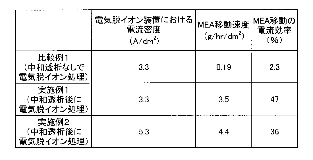

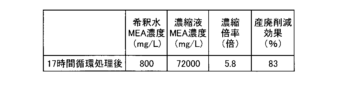
表3より次のことが分かる。
比較例1では、pHが0.1以下でH+濃度が大過剰のコンデミ再生酸性廃液をそのまま電気脱イオン装置で処理したため、MEA移動の電流効率が非常に悪い結果となった。
これに対して、実施例1,2では中和透析でCl-を脱塩すると共に中和しているため、MEA移動速度が上がり、電流効率も著しく高い。
比較例1では、pHが0.1以下でH+濃度が大過剰のコンデミ再生酸性廃液をそのまま電気脱イオン装置で処理したため、MEA移動の電流効率が非常に悪い結果となった。
これに対して、実施例1,2では中和透析でCl-を脱塩すると共に中和しているため、MEA移動速度が上がり、電流効率も著しく高い。
また、表4より明らかなように、中和透析処理後は、Cl-濃度が処理前の40%に削減することができており、中和しながら脱塩が可能であることが分かる。
更に、表5に示されるように、中和透析後の中和脱塩処理液のMEA濃度12500mg/Lに対して、電気脱イオン装置の希釈水のMEA濃度は800mg/Lまで低減され、濃縮液のMEA濃度は72000mg/Lとなった。これは濃縮倍率で5.8倍となり、このような処理をせずにコンデミ再生酸性廃液を産業廃棄物として排出した場合に比べ、産廃削減効果としては83%の削減率を得ることとなり、これを熱分解又は液中燃焼処理する場合の処理コストを大幅に低減することができる。
[比較例2]
コンデミ再生酸性廃液をアニオン交換処理してCl-の脱塩処理を行う実験を行った。
処理フローを図6に示す。
コンデミ再生酸性廃液をアニオン交換処理してCl-の脱塩処理を行う実験を行った。
処理フローを図6に示す。
アニオン交換樹脂5Lを充填したカラムに、コンデミ再生酸性廃液を5L通水し、流出液をアニオン交換処理水として回収した(工程a)。その後、エアー押し出した後(工程b)、2NのNaOH水溶液を1L通水してアニオン交換樹脂を再生した後(工程c)、エアー押し出しし(工程d)、更に純水通水(洗浄)(工程e)を行った。工程b~eの流出液は押出水として回収した。
上記の工程a~eを一度終えた後、再度、工程a~eを行い、アニオン交換処理水、押出水を採取し、アニオン交換処理水は蒸留濃縮に供し、押出水は触媒酸化処理に供した。
この処理におけるコンデミ再生酸性廃液の水質と、アニオン交換処理水の水質と、工程bの流出液の水質を表6に示した。
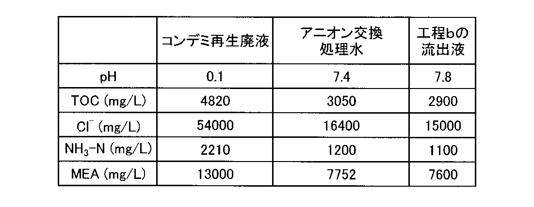
表6より、次のことが分かる。
アニオン交換処理では、中和透析に特有なNa+のリークがなく、Cl-濃度も54000mg/Lから16400mg/Lに低減することはできたが、アニオン交換樹脂中の表面細孔にMEA、NH4 +が水溶液ごと吸着してしまうため、樹脂中に残された液をエアー押し出しした際に、これらの窒素化合物が検出された。つまり、工程bの最初の押出水のMEA濃度だけでも7600mg/Lとなってしまい、さらには、MEAはアニオン交換樹脂に残留するため、2NのNaOH再生液にも1500mg/L、純水洗浄時にも500mg/LのMEAが検出されており、後段の触媒酸化処理が高負荷となり経済的に合わないことが分かる。
アニオン交換処理では、中和透析に特有なNa+のリークがなく、Cl-濃度も54000mg/Lから16400mg/Lに低減することはできたが、アニオン交換樹脂中の表面細孔にMEA、NH4 +が水溶液ごと吸着してしまうため、樹脂中に残された液をエアー押し出しした際に、これらの窒素化合物が検出された。つまり、工程bの最初の押出水のMEA濃度だけでも7600mg/Lとなってしまい、さらには、MEAはアニオン交換樹脂に残留するため、2NのNaOH再生液にも1500mg/L、純水洗浄時にも500mg/LのMEAが検出されており、後段の触媒酸化処理が高負荷となり経済的に合わないことが分かる。
[参考例1]
実施例1において、20日間電気脱イオン装置における処理を継続し、20日後の電圧と陽極室の圧力損失を調べ、初期値に対する増加の程度を求めて結果を表7に示した。
実施例1において、20日間電気脱イオン装置における処理を継続し、20日後の電圧と陽極室の圧力損失を調べ、初期値に対する増加の程度を求めて結果を表7に示した。
[参考例2]
参考例1において、陽極室に、Cl-イオンを含む濃縮液を混合して循環させたこと以外は同様にして処理を行い、同様に20日後の電圧と陽極室の圧力損失を調べ、初期値に対する増加の程度を求めて結果を表7に示した。
この参考例2では、陽極室で次亜塩素酸が発生するためイオン交換樹脂(特にアニオン交換樹脂)が劣化し、粒径が細かくなったイオン交換樹脂が濃縮液循環槽に流入してくる様子が見られた。
参考例1において、陽極室に、Cl-イオンを含む濃縮液を混合して循環させたこと以外は同様にして処理を行い、同様に20日後の電圧と陽極室の圧力損失を調べ、初期値に対する増加の程度を求めて結果を表7に示した。
この参考例2では、陽極室で次亜塩素酸が発生するためイオン交換樹脂(特にアニオン交換樹脂)が劣化し、粒径が細かくなったイオン交換樹脂が濃縮液循環槽に流入してくる様子が見られた。

表7の結果から次のことが分かる。
参考例2では、イオン交換樹脂表面が酸化劣化を受けて一部分解した樹脂が空隙を埋めることで陽極室の圧力損失が上がった上に、おそらくは、樹脂からのイオン交換基の脱落などによって電圧が上昇した。
一方、参考例1では、陽極室での酸化性物質の生成を防止した条件となっているため、参考例2のような劣化挙動は見られなかった。
参考例2では、イオン交換樹脂表面が酸化劣化を受けて一部分解した樹脂が空隙を埋めることで陽極室の圧力損失が上がった上に、おそらくは、樹脂からのイオン交換基の脱落などによって電圧が上昇した。
一方、参考例1では、陽極室での酸化性物質の生成を防止した条件となっているため、参考例2のような劣化挙動は見られなかった。
本発明を特定の態様を用いて詳細に説明したが、本発明の意図と範囲を離れることなく様々な変更が可能であることは当業者に明らかである。
なお、本出願は、2009年11月25日付で出願された日本特許出願(特願2009-267692)に基づいており、その全体が引用により援用される。
なお、本出願は、2009年11月25日付で出願された日本特許出願(特願2009-267692)に基づいており、その全体が引用により援用される。
Claims (10)
- 窒素化合物を含有する酸性液の処理装置であって、
アニオン交換膜によって一方の室と他方の室とに隔てられた前記一方の室に該酸性液を通水すると共に、前記他方の室にアルカリ溶液を通水して該酸性液を中和および脱塩する中和脱塩装置と、
該中和脱塩装置で中和および脱塩された中和脱塩処理液中の窒素化合物を濃縮する濃縮装置と
を有することを特徴とする窒素化合物含有酸性液の処理装置。 - 請求項1において、前記濃縮装置が、蒸留濃縮装置、電気脱イオン装置および電気透析装置のいずれかであることを特徴とする窒素化合物含有酸性液の処理装置。
- 請求項2において、前記濃縮装置が電気脱イオン装置又は電気透析装置であり、該電気脱イオン装置又は電気透析装置の陽極室に通水される陽極水が酸化性の物質又は陽極酸化されて酸化性となる物質を含まないことを特徴とする窒素化合物含有酸性液の処理装置。
- 請求項1ないし3のいずれか1項において、前記中和脱塩処理液のpHが5~9であることを特徴とする窒素化合物含有酸性液の処理装置。
- 請求項1において、窒素化合物が有機アミン化合物であることを特徴とする窒素化合物含有酸性液の処理装置。
- 窒素化合物を含有する酸性液の処理方法であって、
アニオン交換膜によって一方の室と他方の室とに隔てられた前記一方の室に該酸性液を通水すると共に、前記他方の室にアルカリ溶液を通水して該酸性液を中和および脱塩する中和脱塩工程と、
該中和脱塩工程で中和および脱塩された中和脱塩処理液中の窒素化合物を濃縮する濃縮工程と
を有することを特徴とする窒素化合物含有酸性液の処理方法。 - 請求項6において、前記濃縮工程が、蒸留濃縮装置、電気脱イオン装置および電気透析装置のいずれかによる濃縮工程であることを特徴とする窒素化合物含有酸性液の処理方法。
- 請求項7において、前記濃縮工程が電気脱イオン装置又は電気透析装置による濃縮工程であり、該電気脱イオン装置又は電気透析装置の陽極室に、酸化性の物質又は陽極酸化されて酸化性となる物質を含まない陽極水を通水することを特徴とする窒素化合物含有酸性液の処理方法。
- 請求項6ないし8のいずれか1項において、前記中和脱塩処理液のpHが5~9であることを特徴とする窒素化合物含有酸性液の処理方法。
- 請求項6において、窒素化合物が有機アミン化合物であることを特徴とする窒素化合物含有酸性液の処理方法。
Priority Applications (2)
| Application Number | Priority Date | Filing Date | Title |
|---|---|---|---|
| US13/505,394 US20120217162A1 (en) | 2009-11-25 | 2010-11-09 | Apparatus and method for treating nitrogen compound-containing acidic liquid |
| EP10833069.7A EP2505559A4 (en) | 2009-11-25 | 2010-11-09 | TREATMENT DEVICE FOR ACID SOLUTIONS CONTAINING NITROGEN COMPOUNDS, AND PROCESSING METHOD |
Applications Claiming Priority (2)
| Application Number | Priority Date | Filing Date | Title |
|---|---|---|---|
| JP2009-267692 | 2009-11-25 | ||
| JP2009267692 | 2009-11-25 |
Publications (1)
| Publication Number | Publication Date |
|---|---|
| WO2011065222A1 true WO2011065222A1 (ja) | 2011-06-03 |
Family
ID=44066325
Family Applications (1)
| Application Number | Title | Priority Date | Filing Date |
|---|---|---|---|
| PCT/JP2010/069932 WO2011065222A1 (ja) | 2009-11-25 | 2010-11-09 | 窒素化合物含有酸性液の処理装置および処理方法 |
Country Status (4)
| Country | Link |
|---|---|
| US (1) | US20120217162A1 (ja) |
| EP (1) | EP2505559A4 (ja) |
| JP (1) | JP2011131210A (ja) |
| WO (1) | WO2011065222A1 (ja) |
Cited By (4)
| Publication number | Priority date | Publication date | Assignee | Title |
|---|---|---|---|---|
| US10603424B2 (en) | 2011-03-23 | 2020-03-31 | Nxstage Medical, Inc. | Peritoneal dialysis systems, devices, and methods |
| WO2020077918A1 (en) * | 2018-10-17 | 2020-04-23 | Bgt Group Co., Ltd | A bipolar-membrane-based brine recycling system |
| CN113019471A (zh) * | 2021-02-07 | 2021-06-25 | 铜仁市诚一环保科技有限公司 | 一种脱硝催化剂的清洗方法以及设备 |
| US11207454B2 (en) | 2018-02-28 | 2021-12-28 | Nxstage Medical, Inc. | Fluid preparation and treatment devices methods and systems |
Families Citing this family (4)
| Publication number | Priority date | Publication date | Assignee | Title |
|---|---|---|---|---|
| US20130146541A1 (en) | 2011-12-13 | 2013-06-13 | Nxstage Medical, Inc. | Fluid purification methods, devices, and systems |
| CA2899722A1 (en) * | 2013-02-01 | 2014-08-07 | 3M Innovative Properties Company | Rechargeable electrochemical cells |
| EP4108329A4 (en) * | 2020-02-18 | 2023-11-29 | Kabushiki Kaisha F.C.C. | ION EXCHANGER EQUIPMENT |
| GB202019478D0 (en) * | 2020-12-10 | 2021-01-27 | Fujifilm Corp | Purifying polar liquids |
Citations (14)
| Publication number | Priority date | Publication date | Assignee | Title |
|---|---|---|---|---|
| JPH029419A (ja) * | 1988-04-13 | 1990-01-12 | Huels Ag | 溶解したイオン物質の回収法 |
| JPH02180620A (ja) * | 1988-12-29 | 1990-07-13 | Kurita Water Ind Ltd | 脱塩装置 |
| JPH02180621A (ja) * | 1988-12-29 | 1990-07-13 | Kurita Water Ind Ltd | 脱塩装置 |
| JPH03146118A (ja) * | 1989-11-01 | 1991-06-21 | Daido Chem Eng Kk | Al材の表面処理廃液の処理方法 |
| JPH0780253A (ja) * | 1993-09-13 | 1995-03-28 | Chlorine Eng Corp Ltd | 電気透析精製法 |
| JPH09239371A (ja) | 1996-03-07 | 1997-09-16 | Chlorine Eng Corp Ltd | エタノールアミン含有希塩酸廃液の処理法 |
| JPH09314128A (ja) | 1996-03-27 | 1997-12-09 | Japan Organo Co Ltd | 有機アミンを吸着した陽イオン交換樹脂の再生廃液の処理方法 |
| JP2000506442A (ja) * | 1996-10-04 | 2000-05-30 | ロディア | 液状媒体からアミン化合物を抽出する方法 |
| JP3083504B2 (ja) | 1997-10-29 | 2000-09-04 | 東レエンジニアリング株式会社 | イオン交換樹脂再生廃液の処理方法 |
| JP3568298B2 (ja) | 1995-10-23 | 2004-09-22 | 関西電力株式会社 | アミン化合物を含有する発電所排水の処理方法 |
| JP2005066544A (ja) | 2003-08-27 | 2005-03-17 | Japan Organo Co Ltd | モノエタノールアミンの回収方法 |
| JP3739452B2 (ja) | 1995-10-23 | 2006-01-25 | 関西電力株式会社 | アミン化合物を含む発電所排水の処理方法 |
| JP2007007655A (ja) | 2006-10-03 | 2007-01-18 | Ebara Corp | 電気透析装置 |
| JP2009267692A (ja) | 2008-04-24 | 2009-11-12 | Shimada Phys & Chem Ind Co Ltd | 共振器、導波管フィルタ |
Family Cites Families (6)
| Publication number | Priority date | Publication date | Assignee | Title |
|---|---|---|---|---|
| US3165415A (en) * | 1960-10-04 | 1965-01-12 | American Mach & Foundry | Modifying taste of fruit juice by dialysis |
| US3454490A (en) * | 1966-08-10 | 1969-07-08 | Atomic Energy Commission | Concentration of ions using ion selective membranes |
| US5084180A (en) * | 1990-10-25 | 1992-01-28 | Cominco Ltd. | Method for treating zinc-containing sulfate solution |
| US5622681A (en) * | 1992-01-21 | 1997-04-22 | The Dow Chemical Company | Dialysis separation of heat stable organic amine salts in an acid gas absorption process |
| JPH0685669B2 (ja) * | 1992-05-13 | 1994-11-02 | フジライト工業株式会社 | 排泄物処理用粒状材 |
| US8404094B2 (en) * | 2007-04-19 | 2013-03-26 | Trovion Singapore Pte. Ltd., Co. | Method and apparatus for electrodeionization utilizing layered chambers |
-
2010
- 2010-11-09 US US13/505,394 patent/US20120217162A1/en not_active Abandoned
- 2010-11-09 WO PCT/JP2010/069932 patent/WO2011065222A1/ja active Application Filing
- 2010-11-09 EP EP10833069.7A patent/EP2505559A4/en not_active Withdrawn
- 2010-11-25 JP JP2010262511A patent/JP2011131210A/ja active Pending
Patent Citations (14)
| Publication number | Priority date | Publication date | Assignee | Title |
|---|---|---|---|---|
| JPH029419A (ja) * | 1988-04-13 | 1990-01-12 | Huels Ag | 溶解したイオン物質の回収法 |
| JPH02180620A (ja) * | 1988-12-29 | 1990-07-13 | Kurita Water Ind Ltd | 脱塩装置 |
| JPH02180621A (ja) * | 1988-12-29 | 1990-07-13 | Kurita Water Ind Ltd | 脱塩装置 |
| JPH03146118A (ja) * | 1989-11-01 | 1991-06-21 | Daido Chem Eng Kk | Al材の表面処理廃液の処理方法 |
| JPH0780253A (ja) * | 1993-09-13 | 1995-03-28 | Chlorine Eng Corp Ltd | 電気透析精製法 |
| JP3568298B2 (ja) | 1995-10-23 | 2004-09-22 | 関西電力株式会社 | アミン化合物を含有する発電所排水の処理方法 |
| JP3739452B2 (ja) | 1995-10-23 | 2006-01-25 | 関西電力株式会社 | アミン化合物を含む発電所排水の処理方法 |
| JPH09239371A (ja) | 1996-03-07 | 1997-09-16 | Chlorine Eng Corp Ltd | エタノールアミン含有希塩酸廃液の処理法 |
| JPH09314128A (ja) | 1996-03-27 | 1997-12-09 | Japan Organo Co Ltd | 有機アミンを吸着した陽イオン交換樹脂の再生廃液の処理方法 |
| JP2000506442A (ja) * | 1996-10-04 | 2000-05-30 | ロディア | 液状媒体からアミン化合物を抽出する方法 |
| JP3083504B2 (ja) | 1997-10-29 | 2000-09-04 | 東レエンジニアリング株式会社 | イオン交換樹脂再生廃液の処理方法 |
| JP2005066544A (ja) | 2003-08-27 | 2005-03-17 | Japan Organo Co Ltd | モノエタノールアミンの回収方法 |
| JP2007007655A (ja) | 2006-10-03 | 2007-01-18 | Ebara Corp | 電気透析装置 |
| JP2009267692A (ja) | 2008-04-24 | 2009-11-12 | Shimada Phys & Chem Ind Co Ltd | 共振器、導波管フィルタ |
Non-Patent Citations (1)
| Title |
|---|
| See also references of EP2505559A4 |
Cited By (16)
| Publication number | Priority date | Publication date | Assignee | Title |
|---|---|---|---|---|
| US11433169B2 (en) | 2011-03-23 | 2022-09-06 | Nxstage Medical, Inc. | Dialysis systems, devices, and methods |
| US11433170B2 (en) | 2011-03-23 | 2022-09-06 | Nxstage Medical, Inc. | Dialysis systems, devices, and methods |
| US11717601B2 (en) | 2011-03-23 | 2023-08-08 | Nxstage Medical, Inc. | Dialysis systems, devices, and methods |
| US10688235B2 (en) | 2011-03-23 | 2020-06-23 | Nxstage Medical, Inc. | Peritoneal dialysis systems, devices, and methods |
| US11690941B2 (en) | 2011-03-23 | 2023-07-04 | Nxstage Medical, Inc. | Peritoneal dialysis systems, devices, and methods |
| US10898630B2 (en) | 2011-03-23 | 2021-01-26 | Nxstage Medical, Inc. | Peritoneal dialysis systems, devices, and methods |
| US10610630B2 (en) | 2011-03-23 | 2020-04-07 | Nxstage Medical, Inc. | Peritoneal dialysis systems, devices, and methods |
| US10603424B2 (en) | 2011-03-23 | 2020-03-31 | Nxstage Medical, Inc. | Peritoneal dialysis systems, devices, and methods |
| US10688234B2 (en) | 2011-03-23 | 2020-06-23 | Nxstage Medical, Inc. | Peritoneal dialysis systems, devices, and methods |
| US11224684B2 (en) | 2011-03-23 | 2022-01-18 | Nxstage Medical, Inc. | Peritoneal dialysis systems, devices, and methods |
| US11135348B2 (en) | 2011-03-23 | 2021-10-05 | Nxstage Medical, Inc. | Peritoneal dialysis systems, devices, and methods |
| US11364328B2 (en) | 2018-02-28 | 2022-06-21 | Nxstage Medical, Inc. | Fluid preparation and treatment devices methods and systems |
| US11207454B2 (en) | 2018-02-28 | 2021-12-28 | Nxstage Medical, Inc. | Fluid preparation and treatment devices methods and systems |
| US11872337B2 (en) | 2018-02-28 | 2024-01-16 | Nxstage Medical, Inc. | Fluid preparation and treatment devices methods and systems |
| WO2020077918A1 (en) * | 2018-10-17 | 2020-04-23 | Bgt Group Co., Ltd | A bipolar-membrane-based brine recycling system |
| CN113019471A (zh) * | 2021-02-07 | 2021-06-25 | 铜仁市诚一环保科技有限公司 | 一种脱硝催化剂的清洗方法以及设备 |
Also Published As
| Publication number | Publication date |
|---|---|
| JP2011131210A (ja) | 2011-07-07 |
| US20120217162A1 (en) | 2012-08-30 |
| EP2505559A1 (en) | 2012-10-03 |
| EP2505559A4 (en) | 2014-07-02 |
Similar Documents
| Publication | Publication Date | Title |
|---|---|---|
| WO2011065222A1 (ja) | 窒素化合物含有酸性液の処理装置および処理方法 | |
| JP4648307B2 (ja) | 連続式電気脱イオン装置および方法 | |
| US6149788A (en) | Method and apparatus for preventing scaling in electrodeionization units | |
| US20160159671A1 (en) | Method and apparatus for treating water containing boron | |
| KR100874269B1 (ko) | 전처리 공정을 포함한 고효율 해수 전해장치 및 전해방법 | |
| JP2007014827A (ja) | 電気透析装置、排水処理方法、およびフッ素処理システム | |
| WO2008016055A1 (fr) | Électro déioniseur | |
| KR20170002047A (ko) | 음용수 및 초순수급 냉각수 제조시스템 | |
| JP2004283710A (ja) | 純水製造装置 | |
| JP2005000828A (ja) | 純水製造装置 | |
| JP3788318B2 (ja) | 電気脱イオン装置及び電気脱イオン方法 | |
| JP4697758B2 (ja) | 脱塩排水の処理方法及び装置 | |
| JP2011131209A (ja) | 酸性液の処理方法および処理装置 | |
| JP2001191080A (ja) | 電気脱イオン装置及びそれを用いた電気脱イオン化処理方法 | |
| JP3773187B2 (ja) | 脱塩排水の処理方法及び装置 | |
| JP5285135B2 (ja) | 水処理システム及び水処理方法 | |
| JP2011121027A (ja) | 電気式脱イオン水製造装置 | |
| JP7246399B2 (ja) | 純水製造システム及び純水製造方法 | |
| JP2010036173A (ja) | 水処理システム及び水処理方法 | |
| WO2021215099A1 (ja) | 排水処理方法、超純水製造方法及び排水処理装置 | |
| JP2012196630A (ja) | 酸性液の処理装置及び処理方法 | |
| JPH07163845A (ja) | 硝酸アンモニウム含有廃液の処理装置 | |
| JP2012196626A (ja) | 酸性液の処理装置及び処理方法 | |
| JP3202887B2 (ja) | 排水回収方法 | |
| US20230406734A1 (en) | Electrodeionization Configuration for Enhanced Boron Removal |
Legal Events
| Date | Code | Title | Description |
|---|---|---|---|
| 121 | Ep: the epo has been informed by wipo that ep was designated in this application |
Ref document number: 10833069 Country of ref document: EP Kind code of ref document: A1 |
|
| WWE | Wipo information: entry into national phase |
Ref document number: 13505394 Country of ref document: US |
|
| WWE | Wipo information: entry into national phase |
Ref document number: 2010833069 Country of ref document: EP |
|
| NENP | Non-entry into the national phase |
Ref country code: DE |