WO2011052508A1 - パイプ及び該パイプを備えた温水システム - Google Patents
パイプ及び該パイプを備えた温水システム Download PDFInfo
- Publication number
- WO2011052508A1 WO2011052508A1 PCT/JP2010/068731 JP2010068731W WO2011052508A1 WO 2011052508 A1 WO2011052508 A1 WO 2011052508A1 JP 2010068731 W JP2010068731 W JP 2010068731W WO 2011052508 A1 WO2011052508 A1 WO 2011052508A1
- Authority
- WO
- WIPO (PCT)
- Prior art keywords
- pipe
- photoelectric conversion
- conversion element
- water
- layer
- Prior art date
- Legal status (The legal status is an assumption and is not a legal conclusion. Google has not performed a legal analysis and makes no representation as to the accuracy of the status listed.)
- Ceased
Links
Images






Classifications
-
- F—MECHANICAL ENGINEERING; LIGHTING; HEATING; WEAPONS; BLASTING
- F16—ENGINEERING ELEMENTS AND UNITS; GENERAL MEASURES FOR PRODUCING AND MAINTAINING EFFECTIVE FUNCTIONING OF MACHINES OR INSTALLATIONS; THERMAL INSULATION IN GENERAL
- F16L—PIPES; JOINTS OR FITTINGS FOR PIPES; SUPPORTS FOR PIPES, CABLES OR PROTECTIVE TUBING; MEANS FOR THERMAL INSULATION IN GENERAL
- F16L53/00—Heating of pipes or pipe systems; Cooling of pipes or pipe systems
- F16L53/30—Heating of pipes or pipe systems
-
- F—MECHANICAL ENGINEERING; LIGHTING; HEATING; WEAPONS; BLASTING
- F24—HEATING; RANGES; VENTILATING
- F24D—DOMESTIC- OR SPACE-HEATING SYSTEMS, e.g. CENTRAL HEATING SYSTEMS; DOMESTIC HOT-WATER SUPPLY SYSTEMS; ELEMENTS OR COMPONENTS THEREFOR
- F24D11/00—Central heating systems using heat accumulated in storage masses
- F24D11/002—Central heating systems using heat accumulated in storage masses water heating system
- F24D11/003—Central heating systems using heat accumulated in storage masses water heating system combined with solar energy
-
- F—MECHANICAL ENGINEERING; LIGHTING; HEATING; WEAPONS; BLASTING
- F24—HEATING; RANGES; VENTILATING
- F24D—DOMESTIC- OR SPACE-HEATING SYSTEMS, e.g. CENTRAL HEATING SYSTEMS; DOMESTIC HOT-WATER SUPPLY SYSTEMS; ELEMENTS OR COMPONENTS THEREFOR
- F24D18/00—Small-scale combined heat and power [CHP] generation systems specially adapted for domestic heating, space heating or domestic hot-water supply
-
- H—ELECTRICITY
- H02—GENERATION; CONVERSION OR DISTRIBUTION OF ELECTRIC POWER
- H02S—GENERATION OF ELECTRIC POWER BY CONVERSION OF INFRARED RADIATION, VISIBLE LIGHT OR ULTRAVIOLET LIGHT, e.g. USING PHOTOVOLTAIC [PV] MODULES
- H02S40/00—Components or accessories in combination with PV modules, not provided for in groups H02S10/00 - H02S30/00
- H02S40/40—Thermal components
- H02S40/44—Means to utilise heat energy, e.g. hybrid systems producing warm water and electricity at the same time
-
- H—ELECTRICITY
- H10—SEMICONDUCTOR DEVICES; ELECTRIC SOLID-STATE DEVICES NOT OTHERWISE PROVIDED FOR
- H10F—INORGANIC SEMICONDUCTOR DEVICES SENSITIVE TO INFRARED RADIATION, LIGHT, ELECTROMAGNETIC RADIATION OF SHORTER WAVELENGTH OR CORPUSCULAR RADIATION
- H10F77/00—Constructional details of devices covered by this subclass
- H10F77/10—Semiconductor bodies
- H10F77/14—Shape of semiconductor bodies; Shapes, relative sizes or dispositions of semiconductor regions within semiconductor bodies
- H10F77/147—Shapes of bodies
-
- H—ELECTRICITY
- H10—SEMICONDUCTOR DEVICES; ELECTRIC SOLID-STATE DEVICES NOT OTHERWISE PROVIDED FOR
- H10K—ORGANIC ELECTRIC SOLID-STATE DEVICES
- H10K30/00—Organic devices sensitive to infrared radiation, light, electromagnetic radiation of shorter wavelength or corpuscular radiation
- H10K30/50—Photovoltaic [PV] devices
- H10K30/53—Photovoltaic [PV] devices in the form of fibres or tubes, e.g. photovoltaic fibres
-
- F—MECHANICAL ENGINEERING; LIGHTING; HEATING; WEAPONS; BLASTING
- F24—HEATING; RANGES; VENTILATING
- F24D—DOMESTIC- OR SPACE-HEATING SYSTEMS, e.g. CENTRAL HEATING SYSTEMS; DOMESTIC HOT-WATER SUPPLY SYSTEMS; ELEMENTS OR COMPONENTS THEREFOR
- F24D2101/00—Electric generators of small-scale CHP systems
- F24D2101/40—Photovoltaic [PV] modules
-
- F—MECHANICAL ENGINEERING; LIGHTING; HEATING; WEAPONS; BLASTING
- F24—HEATING; RANGES; VENTILATING
- F24D—DOMESTIC- OR SPACE-HEATING SYSTEMS, e.g. CENTRAL HEATING SYSTEMS; DOMESTIC HOT-WATER SUPPLY SYSTEMS; ELEMENTS OR COMPONENTS THEREFOR
- F24D2103/00—Thermal aspects of small-scale CHP systems
- F24D2103/10—Small-scale CHP systems characterised by their heat recovery units
- F24D2103/13—Small-scale CHP systems characterised by their heat recovery units characterised by their heat exchangers
-
- F—MECHANICAL ENGINEERING; LIGHTING; HEATING; WEAPONS; BLASTING
- F24—HEATING; RANGES; VENTILATING
- F24S—SOLAR HEAT COLLECTORS; SOLAR HEAT SYSTEMS
- F24S10/00—Solar heat collectors using working fluids
- F24S10/70—Solar heat collectors using working fluids the working fluids being conveyed through tubular absorbing conduits
-
- F—MECHANICAL ENGINEERING; LIGHTING; HEATING; WEAPONS; BLASTING
- F24—HEATING; RANGES; VENTILATING
- F24S—SOLAR HEAT COLLECTORS; SOLAR HEAT SYSTEMS
- F24S80/00—Details, accessories or component parts of solar heat collectors not provided for in groups F24S10/00-F24S70/00
- F24S2080/09—Arrangements for reinforcement of solar collector elements
-
- Y—GENERAL TAGGING OF NEW TECHNOLOGICAL DEVELOPMENTS; GENERAL TAGGING OF CROSS-SECTIONAL TECHNOLOGIES SPANNING OVER SEVERAL SECTIONS OF THE IPC; TECHNICAL SUBJECTS COVERED BY FORMER USPC CROSS-REFERENCE ART COLLECTIONS [XRACs] AND DIGESTS
- Y02—TECHNOLOGIES OR APPLICATIONS FOR MITIGATION OR ADAPTATION AGAINST CLIMATE CHANGE
- Y02B—CLIMATE CHANGE MITIGATION TECHNOLOGIES RELATED TO BUILDINGS, e.g. HOUSING, HOUSE APPLIANCES OR RELATED END-USER APPLICATIONS
- Y02B10/00—Integration of renewable energy sources in buildings
- Y02B10/10—Photovoltaic [PV]
-
- Y—GENERAL TAGGING OF NEW TECHNOLOGICAL DEVELOPMENTS; GENERAL TAGGING OF CROSS-SECTIONAL TECHNOLOGIES SPANNING OVER SEVERAL SECTIONS OF THE IPC; TECHNICAL SUBJECTS COVERED BY FORMER USPC CROSS-REFERENCE ART COLLECTIONS [XRACs] AND DIGESTS
- Y02—TECHNOLOGIES OR APPLICATIONS FOR MITIGATION OR ADAPTATION AGAINST CLIMATE CHANGE
- Y02B—CLIMATE CHANGE MITIGATION TECHNOLOGIES RELATED TO BUILDINGS, e.g. HOUSING, HOUSE APPLIANCES OR RELATED END-USER APPLICATIONS
- Y02B10/00—Integration of renewable energy sources in buildings
- Y02B10/20—Solar thermal
-
- Y—GENERAL TAGGING OF NEW TECHNOLOGICAL DEVELOPMENTS; GENERAL TAGGING OF CROSS-SECTIONAL TECHNOLOGIES SPANNING OVER SEVERAL SECTIONS OF THE IPC; TECHNICAL SUBJECTS COVERED BY FORMER USPC CROSS-REFERENCE ART COLLECTIONS [XRACs] AND DIGESTS
- Y02—TECHNOLOGIES OR APPLICATIONS FOR MITIGATION OR ADAPTATION AGAINST CLIMATE CHANGE
- Y02B—CLIMATE CHANGE MITIGATION TECHNOLOGIES RELATED TO BUILDINGS, e.g. HOUSING, HOUSE APPLIANCES OR RELATED END-USER APPLICATIONS
- Y02B10/00—Integration of renewable energy sources in buildings
- Y02B10/70—Hybrid systems, e.g. uninterruptible or back-up power supplies integrating renewable energies
-
- Y—GENERAL TAGGING OF NEW TECHNOLOGICAL DEVELOPMENTS; GENERAL TAGGING OF CROSS-SECTIONAL TECHNOLOGIES SPANNING OVER SEVERAL SECTIONS OF THE IPC; TECHNICAL SUBJECTS COVERED BY FORMER USPC CROSS-REFERENCE ART COLLECTIONS [XRACs] AND DIGESTS
- Y02—TECHNOLOGIES OR APPLICATIONS FOR MITIGATION OR ADAPTATION AGAINST CLIMATE CHANGE
- Y02E—REDUCTION OF GREENHOUSE GAS [GHG] EMISSIONS, RELATED TO ENERGY GENERATION, TRANSMISSION OR DISTRIBUTION
- Y02E10/00—Energy generation through renewable energy sources
- Y02E10/50—Photovoltaic [PV] energy
-
- Y—GENERAL TAGGING OF NEW TECHNOLOGICAL DEVELOPMENTS; GENERAL TAGGING OF CROSS-SECTIONAL TECHNOLOGIES SPANNING OVER SEVERAL SECTIONS OF THE IPC; TECHNICAL SUBJECTS COVERED BY FORMER USPC CROSS-REFERENCE ART COLLECTIONS [XRACs] AND DIGESTS
- Y02—TECHNOLOGIES OR APPLICATIONS FOR MITIGATION OR ADAPTATION AGAINST CLIMATE CHANGE
- Y02E—REDUCTION OF GREENHOUSE GAS [GHG] EMISSIONS, RELATED TO ENERGY GENERATION, TRANSMISSION OR DISTRIBUTION
- Y02E10/00—Energy generation through renewable energy sources
- Y02E10/60—Thermal-PV hybrids
Definitions
- the present invention relates to a pipe including an organic photoelectric conversion element, a hot water system and a building including the pipe, and use of the pipe for a temperature riser.
- the form that uses solar energy is broadly divided into a form that converts light into electrical energy and a form that uses heat.
- a solar cell as the former form.
- a photoelectric conversion element that converts sunlight into electrical energy is used to obtain electrical energy from sunlight.
- a solar water heater for heating a medium such as water using solar heat
- a solar power generator for operating a turbine using solar heat and obtaining electric energy by a generator.
- a hybrid system combining both a power generation system using sunlight and a system using solar heat has been studied (for example, Patent Documents 1 to 3).
- a solar cell that is currently in practical use is an inorganic photoelectric conversion element that uses an inorganic semiconductor material in an active layer having photoelectric conversion activity.
- Many of the solar cells that are currently put into practical use require expensive materials such as high-purity silicon, and the high cost is an obstacle to the widespread use of solar cells.
- organic photoelectric conversion element using an organic compound in an active layer is being promoted for an inorganic photoelectric conversion element.
- the organic photoelectric conversion element has advantages such as cost reduction and easy thinning, there are still many problems in terms of photoelectric conversion efficiency and durability.
- the heat collecting part in the conventional solar water heater is a flat plate-shaped device capable of receiving sunlight over a wide area, and its installation location must be limited.
- a hybrid system that combines both a power generation system that uses sunlight and a system that uses solar heat is a form that can effectively use both light and heat. Or it is the form which united the apparatus almost as it is, and the thing which a use form spreads conventionally is not devised about an installation place etc.
- the present invention provides a pipe, a hot water system, and a building adopting the following configuration.
- a pipe comprising a cylindrical pipe body and a sheet-like organic photoelectric conversion element provided on the outer peripheral surface of the pipe body.
- a light condensing layer is further provided on a light receiving surface of the organic photoelectric conversion element.
- a heat transfer layer is provided between the organic photoelectric conversion element and an outer peripheral surface of the pipe body.
- a hot water system comprising a water storage tank, a solar heat collector, and piping, A hot water system in which a part or all of the piping is constituted by the pipe according to any one of [1] to [3].
- a solar heat collector that heats the fluid
- a water tank having a heat exchange unit that exchanges heat between the fluid and water, and a fluid between the solar heat collector and the water tank.
- a hot water system in which a part or all of the piping for delivering the fluid is configured by the pipe according to any one of [1] to [3].
- a hot water system comprising an electric water heater, a solar cell module, and piping, A part or all of the piping is constituted by the pipe according to any one of the above [1] to [3], A hot water system in which both or any one of the photovoltaic power generation module and the pipe is electrically connected so that electric power can be supplied to the electric water heater.
- a water cooling unit that absorbs heat generated in the solar power generation module and circulates water that cools the solar power generation module, and water that has absorbed heat from the solar power generation module is supplied to the electric water heater.
- the hot water system according to the above [7] comprising a pipe connected in this manner.
- a part or all of the piping from the water cooling unit to the electric water heater is constituted by the pipe according to any one of [1] to [3] above, [8] Hot water system as described in. [10] A building including the pipe according to any one of [1] to [3]. [11] Use of the pipe temperature riser according to any one of [1] to [3] above.
- FIG. 1 is a perspective view showing a pipe according to a first embodiment of the present invention.
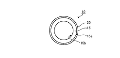
- FIG. 2 is an end view of the pipe according to the first embodiment of the present invention as viewed from the long axis direction.
- FIG. 3 is a diagram showing a basic layer configuration of the organic photoelectric conversion element.
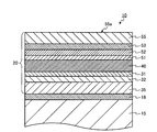
- FIG. 4 is a diagram showing a layer structure in the pipe according to the first embodiment of the present invention.
- FIG. 5 is a diagram showing a layer structure in the pipe of the second embodiment of the present invention.
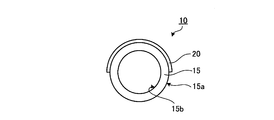
- FIG. 6 is an end view of the pipe according to the third embodiment of the present invention viewed from the long axis direction.
- FIG. 7 is a diagram showing a system according to a fourth embodiment of the present invention.
- FIG. 1 is a perspective view showing a pipe according to a first embodiment of the present invention.
- FIG. 2 is an end view of the pipe according to the first embodiment of the present invention as viewed from the long axis direction.
- FIG. 3 is a diagram showing
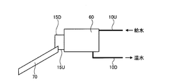
- FIG. 8 is a diagram showing a system according to a fifth embodiment of the present invention.
- FIG. 9 is a diagram showing a system according to the sixth embodiment of the present invention.
- FIG. 10 is a diagram showing a system according to a seventh embodiment of this invention.
- FIG. 11 is a diagram showing a system according to the eighth embodiment of the present invention.
- FIG. 1 shows a pipe 10 according to the first embodiment.
- the pipe 10 is configured by providing a sheet-like organic photoelectric conversion element 20 on the outer peripheral surface of a cylindrical pipe body 15.
- An organic photoelectric conversion element is a photoelectric conversion element containing an organic compound in an active layer for photoelectric conversion.
- An organic photoelectric conversion element usually includes a pair of electrodes and an active layer containing an organic compound between the pair of electrodes.
- the organic photoelectric conversion element can be made thin, and an easily deformable sheet can be adopted as the substrate of the element. Therefore, the organic photoelectric conversion element can be formed into a sheet shape, and the sheet-like organic photoelectric conversion element can be easily installed not only on the flat surface portion but also on the curved surface portion.
- FIG. 2 shows an end view of the pipe 10 of the first embodiment viewed from the long axis direction.
- the sheet-like organic photoelectric conversion element 20 is provided in close contact with the outer peripheral surface 15 a of the pipe body 15 over the entire outer periphery of the pipe body 15.
- the inside of the pipe body 15 is a cavity when not in use, and fluid flows into this cavity when in use.
- the sheet-like organic photoelectric conversion element 20 can receive sunlight and function as a heat collector. When the sheet-like organic photoelectric conversion element 20 is heated, heat can propagate from the outer peripheral surface 15a on the contact surface with the sheet-like organic photoelectric conversion element 20 to the inner peripheral surface 15b with which the fluid contacts. Heat exchange can be performed between the photoelectric conversion element 20 and the fluid.
- the fluid includes fluid such as gas and liquid.
- the sheet-like organic photoelectric conversion element 20 can function as a power generator by receiving sunlight by being electrically wired. Piping for delivering fluid is attached to various parts. Until now, piping has been ignored as a place to install a solar receiver. In fact, in the case of an inorganic photoelectric conversion element, it becomes a rigid element, and it is difficult to produce it so that it can be deformed as it is wound around a cylindrical pipe or the like. However, in this invention, a photoelectric conversion element can be installed in the site
- the pipe body 15 and the sheet-like organic photoelectric conversion element 20 can be prepared separately, and then the sheet-like organic photoelectric conversion element 20 can be wound around the outer periphery of the pipe body 15 and installed. That is, the sheet-like organic photoelectric conversion element 20 can be retrofitted to an existing pipe. Therefore, according to the present invention, the range of usage forms of sunlight is expanded.
- the performance may be better when the element is at a high temperature.
- the element when the photoelectric conversion function is exhibited, the element is at a low temperature. In some cases, the photoelectric conversion efficiency is more easily maintained.
- heat exchange is possible between the fluid flowing inside and the sheet-like organic photoelectric conversion element 20. Accordingly, the fluid flowing inside the pipe 10 is heated to raise the temperature, the temperature rise of the sheet-like organic photoelectric conversion element 20 can be suppressed, and the photoelectric conversion efficiency can be kept good.
- many organic photoelectric conversion elements are easily deteriorated by high temperatures. Therefore, by adopting the configuration of the first embodiment, it is possible to suppress deterioration of the organic photoelectric conversion element due to temperature.
- the pipe 10 according to the first embodiment has a simple configuration, a function as a pipe for delivering a fluid, a function as a temperature riser that raises the temperature by adding heat to the fluid flowing in the pipe, and a power generator Multifunctionality such as the function of the generator and the cooling function of the generator.
- the pipe 10 of 1st Embodiment can be used suitably as piping in the warming device aiming at the heating of a fluid.
- the temperature riser is a device that raises the temperature of a fluid such as liquid or gas, and examples thereof include a water heater.
- the pipe 10 shown in 1st Embodiment can be used suitably as piping of a water heater.
- the pipe 10 shown in 1st Embodiment can be employ
- the sheet-like organic photoelectric conversion element 20 is provided over the entire outer periphery of the pipe body 15.
- the degree of light hitting the outer peripheral surface of the pipe 10 may not be uniform, but from the viewpoint of heat exchange efficiency between the sheet-like organic photoelectric conversion element 20 and the fluid flowing inside the pipe body 15. It is preferable that both have a large contact area. Therefore, when importance is attached to the heat exchange efficiency between the sheet-like organic photoelectric conversion element 20 and the fluid flowing in the pipe body 15, the sheet-like organic photoelectric conversion element 20 is provided over the entire outer periphery of the pipe body 15. preferable.
- the sheet-like organic photoelectric conversion element 20 and the outer peripheral surface 15a of the pipe body 15 are closely fixed with an adhesive.
- the method for fixing the sheet-like organic photoelectric conversion element 20 to the pipe body 15 is not particularly limited, and the design can be changed as appropriate.
- the sheet-like organic photoelectric conversion element 20 is wound around the outer periphery of the pipe body 15, and one side of the sheet-like organic photoelectric conversion element and the other side facing the sheet-like organic photoelectric conversion element are mechanically bonded with a fastener or an adhesive tape. It may be fixed to.
- the organic photoelectric conversion element includes a pair of electrodes and an active layer containing an organic compound. Usually, the active layer is disposed between a pair of electrodes. In the photoelectric conversion element used in the present invention, the active layer is a layer having a function of generating electrical energy when activated by receiving light.
- an organic composition of a p-type organic semiconductor and an n-type organic semiconductor Has a layer.
- the operation mechanism of the photoelectric conversion element of this embodiment will be described.
- Light energy incident from a transparent or translucent electrode is absorbed by an electron-accepting compound (n-type organic semiconductor) such as a fullerene derivative and / or an electron-donating compound (p-type organic semiconductor) such as a conjugated polymer compound. And excitons in which electrons and holes are combined.
- the organic photoelectric conversion element is usually formed on a substrate.
- the organic photoelectric conversion element in the present invention is in the form of a sheet and needs to be deformable so that it can be wound around the outer periphery of a cylindrical member (pipe main body). Therefore, when a substrate is provided on an organic photoelectric conversion element, the substrate can form an electrode on its main surface and does not change chemically when forming a layer constituting the element on the substrate.
- a deformable member is used so that it can be wound around the outer periphery of a cylindrical member (pipe main body). Examples of the material for the substrate include plastics, polymer films, and silicon.
- the opposite electrode (that is, the electrode far from the substrate) is preferably transparent or translucent.
- the thickness of the substrate is preferably 10 ⁇ m to 5000 ⁇ m, more preferably 50 ⁇ m to 3000 ⁇ m.
- An organic photoelectric conversion element has a light receiving region where light enters, and a layer interposed between the light receiving region and the active layer is configured to transmit incident light having a wavelength necessary for power generation.
- the pair of electrodes is formed of a transparent or translucent electrode material.
- the transparent or translucent electrode for example, a conductive metal oxide film, a translucent metal thin film, or the like can be used.
- Specific examples of transparent or translucent electrode materials include indium oxide, zinc oxide, tin oxide, and composites thereof, indium tin oxide (ITO), indium zinc oxide (IZO), NESA, etc. Gold, platinum, silver, copper, etc. are mentioned, and among these, ITO, indium / zinc / oxide, and tin oxide are preferable.
- the other electrode may not be transparent, and as an electrode material of such an electrode, for example, a metal, a conductive polymer, or the like can be used.
- the electrode material include metals such as lithium, sodium, potassium, rubidium, cesium, magnesium, calcium, strontium, barium, aluminum, scandium, vanadium, zinc, yttrium, indium, cerium, samarium, europium, terbium, ytterbium, and the like.
- alloys Two or more of these alloys; one or more of the above metals and one or more metals selected from the group consisting of gold, silver, platinum, copper, manganese, titanium, cobalt, nickel, tungsten and tin; Alloys; and graphite, graphite intercalation compounds, polyaniline and derivatives thereof, polythiophene and derivatives thereof, and the like.
- the alloy include magnesium-silver alloy, magnesium-indium alloy, magnesium-aluminum alloy, indium-silver alloy, lithium-aluminum alloy, lithium-magnesium alloy, lithium-indium alloy, and calcium-aluminum alloy.
- the thickness of the electrode is not particularly limited as long as it can be deformed to such an extent that it can be wound around a cylindrical pipe body when it is formed into a sheet-like organic photoelectric conversion element, but is preferably 10 ⁇ m to 5000 ⁇ m, more preferably 50 ⁇ m to 3000 ⁇ m.
- Examples of the method for producing the electrode include a vacuum deposition method, a sputtering method, an ion plating method, and a plating method.
- organic transparent conductive films such as polyaniline and its derivative (s), polythiophene, and its derivative (s) as an electrode.
- the active layer included in the photoelectric conversion element includes an electron donating compound and an electron accepting compound.
- the electron-donating compound and the electron-accepting compound are relatively determined from the energy level of the energy level of these compounds.
- an organic compound is included as one material constituting either or both of the electron-shared compound and the electron-accepting compound contained in the active layer.
- the active layer may be a single layer or a laminate in which a plurality of layers are stacked.
- Examples of the active layer include a pn heterojunction type in which a layer formed of a p-type semiconductor material (electron-donating layer) and a layer formed of an n-type semiconductor material (electron-accepting layer) are superimposed. It may be an active layer, or may be a bulk heterojunction type active layer in which a p-type semiconductor material and an n-type semiconductor material are mixed to form a bulk heterojunction structure.
- electron donating compounds include pyrazoline derivatives, arylamine derivatives, stilbene derivatives, triphenyldiamine derivatives, oligothiophenes and derivatives thereof, polyvinylcarbazole and derivatives thereof, polysilanes and derivatives thereof, aromatic amines in the side chain or main chain And polysiloxane derivatives, polyaniline and derivatives thereof, polythiophene and derivatives thereof, polypyrrole and derivatives thereof, polyphenylene vinylene and derivatives thereof, polythienylene vinylene and derivatives thereof, and the like.
- electron donating compounds include pyrazoline derivatives, arylamine derivatives, stilbene derivatives, triphenyldiamine derivatives, oligothiophenes and derivatives thereof, polyvinylcarbazole and derivatives thereof, polysilanes and derivatives thereof, aromatic amines in the side chain or main chain And polysiloxane derivatives, polyaniline and derivatives thereof, polythiophene and derivatives thereof, polypyrrole and derivatives thereof, polyphenylene vinylene and derivatives thereof, polythienylene vinylene and derivatives thereof, and the like.
- oligothiophene and its derivatives are preferred, and poly (3-hexylthiophene) (P3HT) is more preferred.
- a compound having a structural unit represented by the following formula (1) is also preferable.
- the compound having a structural unit represented by the formula (1) preferably further has a structural unit represented by the formula (2).
- Ar 1 and Ar 2 are the same or different and represent a trivalent heterocyclic group.
- R 3 and R 4 are the same or different, and R 3 , R 4 , R 5 , R 6 , R 7 and R 8 are hydrogen, halogen, alkyl, alkyloxy, alkylthio, aryl Group, aryloxy group, arylthio group, arylalkyl group, arylalkyloxy group, arylalkylthio group, acyl group, acyloxy group, amide group, acid imide group, imino group, amino group, substituted amino group, substituted silyl group, substituted A silyloxy group, a substituted silylthio group, a substituted silylamino group, a monovalent heterocyclic group, a heterocyclic oxy group, a heterocyclic thio group, an arylalkenyl group, an arylalkynyl group, a carboxyl group, or a cyano group is represented.
- R 50 is a hydrogen group, halogen group, alkyl group, alkyloxy group, alkylthio group, aryl group, aryloxy group, arylthio group, arylalkyl group, arylalkyloxy group, arylalkylthio group, acyl group, acyloxy group, amide Group, acid imide group, imino group, amino group, substituted amino group, substituted silyl group, substituted silyloxy group, substituted silylthio group, substituted silylamino group, monovalent heterocyclic group, heterocyclic oxy group, heterocyclic thio group, aryl An alkenyl group, an arylalkynyl group, a carboxyl group or a cyano group is represented.
- R 51 is an alkyl group having 6 or more carbon atoms, an alkyloxy group having 6 or more carbon atoms, an alkylthio group having 6 or more carbon atoms, an aryl group having 6 or more carbon atoms, or an aryloxy group having 6 or more carbon atoms
- X 1 and Ar 2 are bonded to the adjacent position of the heterocyclic ring contained in Ar 1
- C (R 50 ) (R 51 ) and Ar 1 are bonded to the adjacent position of the heterocyclic ring contained in Ar 2. Yes.
- examples of the compound having the structural unit represented by the formula (1) include a polymer (polymer compound B) represented by the following formula (5).
- the electron donating compound a polymer compound having a polystyrene-equivalent weight average molecular weight of 3,000 to 10,000,000 calculated using a standard polystyrene sample is preferable. If the weight average molecular weight is less than 3000, defects may occur in film formation at the time of device preparation, and if it is greater than 10000000, solubility in a solvent and applicability at the time of device preparation may be reduced.
- the weight average molecular weight of the electron donating compound is more preferably 8000 to 5000000, and particularly preferably 10,000 to 1000000.
- the electron donating compounds may be used alone or in combination of two or more.
- electron accepting compounds include oxadiazole derivatives, anthraquinodimethane and its derivatives, benzoquinone and its derivatives, naphthoquinone and its derivatives, anthraquinone and its derivatives, tetracyanoanthraquinodimethane and its derivatives, fluorenone derivatives, diphenyldicyanoethylene and derivatives thereof, diphenoquinone derivatives, metal complexes of 8-hydroxyquinoline and its derivatives, polyquinoline and its derivatives, polyquinoxaline and its derivatives, polyfluorene and its derivatives, fullerene and derivatives thereof such as C 60 fullerene, bathocuproine etc.
- Phenanthrene derivatives metal oxides such as titanium oxide, carbon nanotubes, and the like.
- titanium oxide, carbon nanotubes, fullerenes, and fullerene derivatives are preferable, and fullerenes and fullerene derivatives are particularly preferable.
- fullerene examples include C 60 fullerene, C 70 fullerene, C 76 fullerene, C 78 fullerene, such as C 84 fullerene, and the like.
- the fullerene derivative C 60 fullerene, C 70 fullerene, C 76 fullerene, C 78 fullerene include derivatives of C 84 fullerenes.
- Specific examples of the fullerene derivative include the following structures.
- fullerene derivatives include [6,6] phenyl-C 61 butyric acid methyl ester (C 60 PCBM, [6,6] -Phenyl C 61 butyric acid methyl ester), and [6,6] phenyl-C 71 butyric acid.
- Methyl ester (C 70 PCBM, [6,6] -Phenyl C 71 butyric acid methyl ester), [6,6] Phenyl-C 85 butyric acid methyl ester (C 84 PCBM, [6,6] -Phenyl C 85 butyric acid methyl ester), and the like [6,6] thienyl -C 61 butyric acid methyl ester ([6,6] -Thienyl C 61 butyric acid methyl ester).
- the ratio of the fullerene derivative is preferably 10 parts by weight to 1000 parts by weight and preferably 20 parts by weight to 500 parts by weight with respect to 100 parts by weight of the electron donating compound. It is more preferable.
- the thickness of the active layer is usually preferably 1 nm to 100 ⁇ m, more preferably 2 nm to 1000 nm, still more preferably 5 nm to 500 nm, more preferably 20 nm to 200 nm.
- the active layer may be manufactured by any method, and examples of the manufacturing method include a film forming method using a solution containing an organic compound and a film forming method by vacuum deposition.
- a solvent capable of dissolving the material of the active layer may be appropriately selected.
- solvents for dissolving organic compounds used in the active layer include unsaturated hydrocarbons such as toluene, xylene, mesitylene, tetralin, decalin, bicyclohexyl, butylbenzene, sec-butylbenzene, tert-butylbenzene, etc.
- Solvents carbon tetrachloride, chloroform, dichloromethane, dichloroethane, chlorobutane, bromobutane, chloropentane, bromopentane, chlorohexane, bromohexane, chlorocyclohexane, bromocyclohexane, and other halogenated saturated hydrocarbon solvents, chlorobenzene, dichlorobenzene, tri Examples thereof include halogenated unsaturated hydrocarbon solvents such as chlorobenzene and ether solvents such as tetrahydrofuran and tetrahydropyran.
- spin coating method for film formation, spin coating method, casting method, micro gravure coating method, gravure coating method, bar coating method, roll coating method, wire bar coating method, dip coating method, spray coating method, screen printing method, gravure printing method, Application methods such as flexographic printing method, offset printing method, ink jet printing method, dispenser printing method, nozzle coating method, capillary coating method can be used, spin coating method, flexographic printing method, gravure printing method, ink jet printing method, dispenser A printing method is preferred.
- An additional intermediate layer other than the active layer may be used as a means for improving the photoelectric conversion efficiency.
- the intermediate layer is provided for the purpose of improving photoelectric conversion efficiency, for example.
- examples of the intermediate layer include a charge transport layer (hole transport layer or electron transport layer), a charge block layer (hole block layer or electron block layer), and a buffer layer. It is done.
- an alkali metal such as lithium fluoride (LiF), a halide of an alkaline earth metal, an oxide, or the like can be used.
- fine particles of inorganic semiconductor such as titanium oxide, PEDOT (poly-3,4-ethylenedioxythiophene), and the like can be given.
- the method for forming the intermediate layer is not particularly limited, and various thin film forming methods can be appropriately selected in consideration of conditions such as the type of material and the thickness of the designed layer.
- a method similar to the film forming method such as the above-described coating method is exemplified.
- a vacuum deposition method, a sputtering method, an ion plating method, a chemical vapor deposition method (CVD method), a plating method, or the like may be employed.
- each intermediate layer is not particularly limited as long as it can be deformed to the extent that it can be wound around a cylindrical pipe body when a sheet-like organic photoelectric conversion element is formed, but it is preferably 0.1 ⁇ m to 500 ⁇ m. More preferably, the thickness is 1 ⁇ m to 100 ⁇ m.
- the effective photoelectric conversion element 20 shown in FIG. 3 includes a pair of electrodes composed of a first electrode 32 and a second electrode 52, and an active layer 40 disposed between the pair of electrodes.
- One of the first electrode 32 and the second electrode 52 serves as an anode, and the other serves as a cathode. Which electrode becomes the anode or the cathode can be arbitrarily designed.
- a first intermediate layer 31 is provided between the first electrode 32 and the active layer 40.
- a second intermediate layer 51 is provided between the second electrode 52 and the active layer 40.
- the active layer 40 is a single layer.
- the active layer 40 may be an active layer having a pn heterojunction type two-layer configuration, or to the bulk.
- An active layer having a terror type single layer structure may be used.
- the first intermediate layer 31 and the second intermediate layer 51 are arbitrary layers, and either one or both may be omitted. Further, in the layer configuration shown in FIG. 3, each intermediate layer is a single layer, but each intermediate layer may be composed of a plurality of layers.
- the pattern of the layer structure that can be taken by the organic photoelectric conversion element is expressed as, for example, the following a) to h).
- “electron supply layer / electron acceptor layer” represents a pn heterojunction active layer.
- the layer configuration may be either a form in which the anode is provided on the side closer to the pipe body 15 or a form in which the cathode is provided on the side closer to the pipe body 15.
- the intermediate layer can be various functional layers.
- the intermediate layer include a charge transport layer, a charge block layer, and a buffer layer.
- the intermediate layer provided between the anode and the active layer is a hole transport layer
- the intermediate layer provided between the cathode and the active layer is an electron transport layer.
- the intermediate layer provided between the anode and the active layer is an electron blocking layer
- the intermediate layer provided between the cathode and the active layer is a hole blocking layer.
- the organic photoelectric conversion element 20 used in the present invention may have any of the above layer configurations.
- a sealing layer, a substrate, and the like can be further provided on the outer surface of the electrode of the organic photoelectric conversion element 20 (the surface farther from the pipe body 15) as necessary.
- other configurations such as a protective film and an optical film may be provided.
- a protective film, an optical film, or the like is further provided as a light collecting layer, the light collecting layer may be provided so as to be bonded to the light receiving surface of the sheet-like organic photoelectric conversion element.
- FIG. 4 shows a layer configuration of the pipe 10 in which the sheet-like organic photoelectric conversion element 20 is attached to the outer peripheral surface 15a of the pipe 15 as the first embodiment.
- the sheet-like organic photoelectric conversion element 20 shown in FIG. 4 is arranged in order from the side closer to the pipe body 15 (lower in FIG. 4) to the side farther (upward in FIG. 4), the first substrate 35, the first electrode 32, The intermediate layer 31, the active layer 40, the second intermediate layer 51, the second electrode 52, the sealing layer 53, and the second substrate 55 are stacked.
- the sheet-like organic photoelectric conversion element 20 is tightly fixed to the outer peripheral surface of the pipe body 15 with an adhesive.
- a portion where the adhesive is present is represented as an adhesive layer 19.
- a layer (heat transfer layer) formed of a high heat transfer material is provided on the surface of the first substrate 35 facing the pipe body 15, and the heat conductivity to the pipe body 15 is provided. May be improved.
- the material for forming the heat transfer layer include metals such as Cu, Ti, Fe, W, and Al, or expanded metals made of these metals.
- the second substrate 55 forms a light receiving region, and light enters the active layer 40 from the light receiving surface 55 a that is the exposed surface of the second substrate 55.
- the sealing layer 53 blocks each layer such as the second electrode 52 and the active layer 40 provided on the inner side (side closer to the pipe body 15) from the outside air.
- the sealing layer 53 is preferably a layer impermeable to water, oxygen, or the like.
- the first substrate 35 is appropriately designed according to the function of the sheet-like organic photoelectric conversion element 20.
- the first substrate 35 provides a bonding surface with the pipe body 15.
- the first substrate 35 may be used as a support substrate for sequentially laminating each layer at the time of manufacturing the element.
- the first substrate 35 may be an insulating layer. Further, when importance is attached to the thermal conductivity with respect to the pipe body 15, the first substrate 35 may be provided as a layer having a high thermal conductivity.
- the second substrate 55 can function as a protective layer for protecting the inside of the sheet-like organic photoelectric conversion element 20. Further, the second substrate 55 may be configured by an optical film. For example, as the second substrate 55, an optical film having a light collecting property or the like can be provided.
- the organic photoelectric conversion element has a greater range of light utilization efficiency by condensing scattered light and radiation light on the active layer than the inorganic photoelectric conversion element.
- an organic photoelectric conversion element since an organic photoelectric conversion element is employ
- the adhesive used for adhesion between the sheet-like organic photoelectric conversion element 20 and the pipe body 15 may be appropriately selected according to both materials. Moreover, since it is suitable to install the pipe of this invention in the place exposed to sunlight etc. for a long time, it is preferable that the contact bonding layer 19 has heat resistance.
- the pipe body 15 is not particularly limited except that it is cylindrical. There is no restriction
- various members used as fluid piping can be used. Examples of the pipe body 15 include a metal pipe, a plastic pipe, and a wooden pipe.
- the pipe 10 of the present invention has a function of raising the temperature of the fluid flowing through the pipe body 15. Assuming that the pipe 10 of the present invention is used in the hot water system, for example, a plastic cylindrical member is suitable as the pipe body 15.
- Second embodiment of the present invention (pipe) A second embodiment of the present invention will be described with reference to FIG.
- symbol is attached
- the layer is comprised so that the pipe main body 15 and the 1st electrode 32 may contact
- the first electrode 32 is made of a conductive material. Many conductive materials are excellent in thermal conductivity. Therefore, by providing the first electrode 32 in close contact with the pipe body 15, heat from the sheet-like organic photoelectric conversion element 20 can be efficiently transmitted to the fluid flowing in the pipe body 15. That is, the first electrode 32 is also used as a heat transfer layer. According to 2nd Embodiment, while reducing the member called a board
- the pipe body 15 is insulated. You may let the body play a role.
- the sheet-like organic photoelectric conversion element 20 is used not only as a heat collector but also as a power generator, and the pipe body 15 is formed of a conductive material, It is preferable to provide an insulator on a part of the pipe body 15 formed.
- Third embodiment of the present invention (pipe) A third embodiment of the present invention will be described with reference to FIG.
- symbol is attached
- the sheet-like photoelectric conversion element 20 is provided not on the entire circumference of the outer periphery of the pipe body 15 but on a substantially half circumference. That is, the sheet-like photoelectric organic conversion element may be provided in a part of the pipe body 15 according to a region where good light reception is possible.
- the pipe 10 of this embodiment can be configured such that the sheet-like organic photoelectric conversion element 20 is provided only on the light receiving portion of the outer peripheral surface 15 a of the pipe body 15.
- the pipe 10 of this embodiment is good also as a structure by which the sheet-like organic photoelectric conversion element 20 is provided in at least one part of the outer peripheral surface 15a of the pipe main body 15 in the light-receiving part.
- FIG. 7 shows an outline of the fourth embodiment of the present invention.
- symbol is attached
- the water storage tank 60 and the pipe 10 of the present invention are provided as part of the piping connected to the water storage tank 60.
- FIG. 7 shows an example of a configuration in which part of the piping is the pipe 10 of the present invention, but the entire piping may be the pipe 10 of the present invention.
- the pipe 10 is provided at a location upstream of the water storage tank 60 and capable of receiving outdoor sunlight.
- the pipe 10 may be a water supply path to the water storage tank 60 and may be installed on the rooftop or may be installed on the ground.
- the portion that cannot receive light is piped by a pipe body 15 (hereinafter sometimes referred to as a normal pipe) in which the sheet-like organic photoelectric conversion element 20 is not provided.
- the pipe 10 used in the hot water system has not only the configuration in which the sheet-like organic photoelectric conversion element 20 is provided only in the light receiving portion of the outer peripheral surface 15a of the pipe main body 15 as described above, but also the outer peripheral surface 15a of the pipe main body 15.
- the sheet-like organic photoelectric conversion element 20 is provided in at least one part of the light-receiving part. Moreover, it is good also as a structure which provides the sheet-like organic photoelectric conversion element 20 in the whole outer peripheral surface 15a including the part which cannot receive light (it is the same also in embodiment of the following hot water systems). According to the fourth embodiment, it is possible to warm water upstream of the water storage tank 60.
- the water storage tank 60 may be a water heater having a function of heating water in the tank.
- An example of such a water heater is an electric water heater.
- the water storage tank 60 is an electric water heater, since the temperature of the water supplied to the electric water heater is high, the heating load by the electric water heater can be reduced, and the externally supplied power from a power plant or substation Contributes to power saving.
- the pipe 10 can be supplied with electric power by the sheet-like organic photoelectric conversion element 20.
- the electric power supplied from the sheet-like organic photoelectric conversion element 20 may be used as electric power supplied to the electric water heater, or may be used as an auxiliary power source in a building where the hot water system is installed.
- the sheet-like organic photoelectric conversion element 20 is demonstrating the photoelectric conversion function, it may be preferable from a viewpoint of photoelectric conversion efficiency to suppress the temperature rise of the sheet-like organic photoelectric conversion element 20.
- heat is exchanged between the water flowing in the pipe 10 and the sheet-like organic photoelectric conversion element 20, the water is heated and used, and the temperature rise of the sheet-like organic photoelectric conversion element 20 is suppressed. The advantage that preferable photoelectric conversion efficiency can be maintained can be obtained.
- FIG. 8 shows an outline of the fifth embodiment.
- symbol is attached
- the pipe 10 of the said this invention is provided as some piping connected with a solar water heater.
- the entire piping may be the pipe 10 of the present invention.
- the solar water heater shown in FIG. 8 is a natural circulation solar water heater, and includes a water storage tank 60 and a heat collecting plate (solar heat collector) 70, and the water storage tank 60 via the pipe body 15U and the pipe body 15D. Water circulates between the heat collector 70 and the heat collecting plate 70.
- the natural circulation type solar water heater water is supplied from the water storage tank 60 through the pipe body 15U into the heat collecting plate, and the water circulates through the heat collecting plate to add heat, and the heated water passes through the pipe body 15D.
- the cycle of returning to the water storage tank 60 proceeds by convection using solar heat.
- Water is supplied to the water storage tank 60 through a pipe 10U connected upstream thereof, while water (hot water) heated through a pipe 10D connected downstream is delivered to the outside.
- a pipe 10U upstream of the water storage tank 60
- the temperature of the water supplied to the water storage tank 60 can be increased and supplied, and the time required for heating to the desired temperature can be shortened.
- the pipe 10 ⁇ / b> D downstream of the water storage tank 60 it is possible to suppress the temperature drop of the hot water supplied from the water storage tank 60.
- Natural circulation solar water heaters are generally installed in places where sunlight is well received, for example, on the rooftops of buildings. Therefore, by using the pipe 10 of the present invention in the pipe for supplying water to the natural circulation type solar water heater and the pipe for delivering hot water to the outside, more effective use of sunlight becomes possible.
- FIG. 9 shows an outline of the sixth embodiment.
- a mark is attached to drawing and description is abbreviate
- the pipe 10 of the present invention is provided as a part of the pipe connected to the forced circulation solar water heater.
- FIG. 9 shows an example of a configuration in which a part of the piping is the pipe 10 of the present invention, but the entire piping may be the pipe 10 of the present invention.
- the heat collecting plate 70 uses a fluid such as water or antifreeze.
- the forced circulation solar water heater has a system for circulating fluid. Since the fluid only needs to be circulated, there is an advantage that the water storage tank does not necessarily need to be installed at a high position such as a rooftop with a heat collecting plate.
- the fluid stored in the fluid tank 64 is pumped up to the heat collecting plate 70 by a pump, and the fluid heated by the heat collecting plate 70 is stored in the water storage tank (warm water).
- the water that has been delivered to the heat exchanging unit 63 provided in the vessel 62 and stored in the water storage tank 62 is heated. Water is supplied to the water storage tank 62 from the pipe body 15U, and hot water is sent out from the pipe 15D.
- the pipe 10U is provided in the upstream portion of the heat collecting plate 70 and the pipe 10D is provided in the downstream portion of the heat collecting plate 70 as a part of the pipe for delivering the fluid.
- the fluid can be heated not only in the heat collecting plate 70 but also in the piping, so that the sunlight can be used efficiently.
- FIG. 10 shows an outline of the seventh embodiment.
- symbol is attached
- 7th Embodiment is the form which combined the solar water heater provided with 60 A of 1st water storage tanks and the solar heat collecting plate 70, and the electric water heater as the 2nd water storage tank 60B.
- the solar water heater provided with the first water tank 60A and the heat collecting plate 70 is the same as that shown in the fifth embodiment.
- the solar water heater is installed in a place such as a rooftop of a building and receives direct sunlight.
- a part of the piping for supplying water to the first water tank 60A is constituted by a pipe 10U (10), and the heated water is supplied to the first water tank 60A.
- the second water tank 60B is an electric water heater. There are two paths for supplying water to the second water tank, one of which is supplied from the first water tank 60A and the other is supplied from an external water source.
- a part of the pipe connecting the first water tank 60A and the second water tank is constituted by a pipe 10D (10), and the second water reservoir is heated while warming the warm water heated in the first water tank 60A.
- Hot water can be supplied to the tank 60B.
- Hot water is delivered from the second water tank 60B through the pipe body 15D.
- the electric water heater that is the second water tank 60B can reheat the hot water supplied from the first water tank 60A or raise the temperature to a higher temperature than the hot water supplied from the first water tank. . Since the water supplied from the first water tank 60A to the electric water heater is warm water heated by the heat collecting plate 70 or the pipe 10D, it is possible to reduce the heating load by the electric water heater, Contributes to the power saving of externally supplied power supplied from substations.
- the pipes 10U and 10D can also supply electric power by the sheet-like organic photoelectric conversion element 20, the electric power supplied from the sheet-like organic photoelectric conversion element 20 is supplied to the electric water heater as the second water storage tank. It can be used as electric power, and can also be used as electric power in buildings where the hot water system is installed. Thus, effective use of sunlight is possible by combining the solar water heater, the electric water heater, and the pipe 10 of the present invention.
- FIG. 11 shows an outline of the eighth embodiment.
- symbol is attached
- a solar-powered hybrid device 80 having a solar cell module 81 and a water cooling unit 83 for cooling the solar cell module 81 is provided.
- the solar cell module 81 is configured by integrating a plurality of organic photoelectric conversion elements.
- the solar-powered hybrid device 80 is installed in a place such as a rooftop of a building, for example, and receives direct sunlight.
- the electric power supplied from the solar cell module 81 can be supplied to the building where the hot water system is installed and the electric water heater 66.
- a water cooling unit 83 is provided to cool the solar cell module 81.
- Water cooling unit 83 water is supplied from the outside through a pipe body 15U 1. Because water supplied to the water cooling unit 83 is used for the water cooling of the solar cell module 81, the pipe body 15U 1 without using the heating pipe of the present invention, it is constituted by a conventional pipe.
- the water cooling unit 83 is piped so that water circulates in the unit 83, and water passes through the pipe 83 and absorbs heat generated from the solar cell module 81. In this way, the solar cell module 81 is cooled.
- the water that has absorbed the heat is sent from the water cooling unit 83 to the electric water heater 66.
- a pipe connecting the water cooling unit 83 and the electric water heater 66 is provided with a pipe 10D (10). Therefore, water that has absorbed heat by the water cooling unit 83 can be supplied to the electric water heater 66 while further heating.
- the heating load in the electric water heater 66 can be reduced.
- the pipe 10 ⁇ / b> D can also supply power by the sheet-like organic photoelectric conversion element 20, the power supplied from the sheet-like organic photoelectric conversion element 20 may be used as power to be supplied to the electric water heater 66. Alternatively, it can be used as electric power in a building where a hot water system is installed. In this way, by using the solar cell module 81 and the solar-powered hybrid device 80 having the water-cooling unit 83 for cooling the solar cell module 81 and the pipe 10D in combination, the solar light can be effectively used in a wide variety of ways.
- Example 1 (Creation of an organic photoelectric conversion element)
- the ITO film of a PEN (polyethylene naphthalate) film (substrate) on which an ITO film having a thickness of about 150 nm was formed by sputtering was patterned, washed with an organic solvent, an alkaline detergent, and ultrapure water and dried.
- the PEN film provided with the patterned ITO film was subjected to UV-O 3 treatment using a UV-O 3 apparatus.
- an orthodichlorobenzene solution having a weight ratio of 1: 0.8 between P3HT as an electron-donating polymer material and [5,6] -phenyl C 61 butyric acid methyl ester ([5,6] -PCBM). was prepared.
- the amount of P3HT added was 1% by weight with respect to orthodichlorobenzene.
- filtration was performed with a 0.2 ⁇ m diameter filter.
- the obtained solution was spin-coated and then dried in an N 2 atmosphere to form an active layer.
- an LiF film having a thickness of about 2.3 nm and an Al film having a thickness of about 70 nm were formed in a resistance heating vapor deposition apparatus to form an electrode. Furthermore, the sealing process was given by adhere
- an epoxy resin rapid hardening type Araldite
- Example 2 (Creation of an organic photoelectric conversion element)
- the PEN film ITO film on which an ITO film having a thickness of about 150 nm was formed by sputtering was patterned, washed with an organic solvent, an alkaline detergent, and ultrapure water, and dried.
- the PEN film provided with the patterned ITO film was subjected to UV-O 3 treatment using a UV-O 3 apparatus.
- an orthodichlorobenzene solution having a weight ratio of 1: 2 between the polymer compound A and [5,6] -phenyl C 61 butyric acid methyl ester ([5,6] -PCBM) was prepared.
- the amount of the polymer compound A added was 0.5% by weight with respect to orthodichlorobenzene.
- the polymer compound A had a polystyrene equivalent weight average molecular weight of 17,000 and a polystyrene equivalent number average molecular weight of 5,000.
- the light absorption edge wavelength of the polymer A was 925 nm.
- An electrode was formed on the formed active layer by depositing a LiF film with a thickness of about 2.3 nm and an Al film with a thickness of about 70 nm in a resistance heating vapor deposition apparatus. Furthermore, the sealing process was given by adhere
- an epoxy resin rapid hardening type Araldite
- Example 3 (Creation of an organic photoelectric conversion element)
- the PEN film ITO film on which an ITO film having a thickness of about 150 nm was formed by sputtering was patterned, washed with an organic solvent, an alkaline detergent, and ultrapure water, and dried.
- the PEN film provided with the patterned ITO film was subjected to UV-O 3 treatment using a UV-O 3 apparatus.
- an orthodichlorobenzene solution having a weight ratio of 1: 3 of polymer compound B as an electron-donating polymer material and [5,6] -phenyl C 61 butyric acid methyl ester ([5,6] -PCBM) was prepared.
- the amount of the polymer compound B added was 0.5% by weight with respect to the orthodichlorobenzene solution.
- filtration was performed with a 0.2 ⁇ m diameter filter.
- the obtained solution was spin-coated and then dried in an N 2 atmosphere to form an active layer.
- an LiF film having a thickness of about 2.3 nm and an Al film having a thickness of about 70 nm were formed in a resistance heating vapor deposition apparatus to form an electrode. Furthermore, the sealing process was given by adhere
- an epoxy resin rapid hardening type Araldite
- Comparative Examples 1 to 3 a film-like organic thin-film solar cell produced by the same method as in Examples 1 to 3 was attached to a pipe that does not allow running water through a copper foil.
- the efficiency retention of the organic thin film solar cells of Examples 1 to 3 was higher than the efficiency retention of the organic thin film solar cells of Comparative Examples 1 to 3. That is, the organic thin film solar cells of Examples 1 to 3 had higher durability.
- the organic thin-film solar cell 60 minutes after the comparative example 2 was damaged by peeling by the thermal expansion of the film.
- the pipe of the present invention has a function of increasing the temperature by adding heat to the fluid, it can be used for a hot water system or the like, and the solar energy can be effectively used.
Landscapes
- Engineering & Computer Science (AREA)
- General Engineering & Computer Science (AREA)
- Mechanical Engineering (AREA)
- Physics & Mathematics (AREA)
- Combustion & Propulsion (AREA)
- Thermal Sciences (AREA)
- Chemical & Material Sciences (AREA)
- Sustainable Energy (AREA)
- Sustainable Development (AREA)
- Life Sciences & Earth Sciences (AREA)
- Electromagnetism (AREA)
- Photovoltaic Devices (AREA)
- Rigid Pipes And Flexible Pipes (AREA)
- Heat-Pump Type And Storage Water Heaters (AREA)
- Pipe Accessories (AREA)
Abstract
太陽エネルギーの利用形態の幅を広げ、太陽エネルギーの有効活用を図る。円筒状のパイプ本体(15)と、該パイプ本体の外周面に設けられたシート状の有機光電変換素子(20)とを具備する、パイプ(10)は、温水システム、建築物に利用できる。
Description
本発明は、有機光電変換素子を具備するパイプ、該パイプを備えた温水システムおよび建築物、並びに該パイプの昇温器のための使用に関する。
太陽エネルギーを利用する形態は、光を電気的エネルギーに変換する形態と、熱を利用する形態とに大別される。前者の形態としては、太陽電池がある。太陽電池では、太陽光を電気エネルギーに変換する光電変換素子を利用し、太陽光から電気エネルギーを得る。これに対して後者の形態としては、太陽熱を利用して水などの媒体を温める太陽熱温水器、太陽熱を利用してタービンなど作動させ発電機によって電気エネルギーを得る太陽熱発電装置などがある。さらに、太陽光を利用する発電のシステムと太陽熱を利用するシステムとの両者を組み合わせたハイブリッド型のシステムも検討されている(例えば、特許文献1~3)。
現在実用化が進んでいる太陽電池は、光電変換活性を備える活性層に無機半導体材料を用いている無機光電変換素子である。現状実用化されている太陽電池の多くは、高純度シリコンなどのように高価な材料を要するものであり、コスト高が太陽電池の広い普及を阻む1つの障害となっている。
また無機光電変換素子を薄膜化することは必ずしも容易ではなく、無機光電変換素子を搭載した太陽電池モジュールとして実用化されているものは、厚みのある平板形状の筐体内に素子が実装された装置であり、形状可変性に乏しい。そのため無機光電変換素子を搭載した太陽電池モジュールの設置場所は限定的にならざるを得ない。
無機光電変換素子に対して、活性層に有機化合物を用いる有機光電変換素子の開発が進められている。有機光電変換素子は、コストを低減できる、薄膜化が容易といった利点があるものの、光電変換効率、耐久性などの点で、未だ課題が多い。
従来から利用されてきた太陽熱温水器は、太陽熱が強い時期には十分高温な温水を得ることができるが、そうではない時期は、それ自体で十分高温な温水を得ることは困難である。また従来の太陽熱温水器における集熱部は、太陽光を広い面積で受光可能な平板型形状の装置となっており、その設置場所は限定的にならざるを得ない。
太陽光を利用する発電のシステムと太陽熱を利用するシステムとの両者を組み合わせたハイブリッド型のシステムは、光と熱との双方を有効に活用し得る形態ではあるが、今のところ、それぞれの装置または器具をほぼそのまま合体させた形態であり、設置場所などに関してまで従来より利用形態が広がるものは考案されていない。
以上のような状況の下、太陽エネルギーの利用形態の幅を拡張し、太陽エネルギーのより一層の有効活用を図ることが望まれる。本発明はこのような状況に鑑みなされたものであり、太陽エネルギーの利用形態の幅を広げ、太陽エネルギーの有効活用を図るものである。
本発明は、下記構成を採用したパイプ、温水システム、および建築物を提供する。
〔1〕円筒状のパイプ本体と、該パイプ本体の外周面に設けられたシート状の有機光電変換素子とを具備する、パイプ。
〔2〕前記有機光電変換素子の受光面に、集光層がさらに設けられている、上記〔1〕に記載のパイプ。
〔3〕前記有機光電変換素子と前記パイプ本体の外周面との間に伝熱層が設けられている、上記〔1〕または〔2〕に記載のパイプ。
〔4〕上記〔1〕から〔3〕のいずれか一項に記載のパイプを備える温水システム。
〔5〕貯水槽と、太陽熱集熱器と、配管とを備える温水システムであって、
前記配管のうちの一部又は全部が、上記〔1〕から〔3〕のいずれか一項に記載のパイプにより構成されている温水システム。
〔6〕流体を加温する太陽熱集熱器と、前記流体と水との間で熱交換を行う熱交換部を有する貯水槽と、前記太陽熱集熱器と前記貯水槽との間で流体を循環させる循環ポンプと、前記流体を配送する配管とを備え、
前記流体を配送する配管のうちの一部又は全部が、上記〔1〕から〔3〕のいずれか一項に記載のパイプにより構成されている温水システム。
〔7〕電気温水器と太陽電池モジュールと配管とを備える温水システムであって、
前記配管のうちの一部又は全部が、上記〔1〕から〔3〕のいずれか一項に記載のパイプにより構成されており、
前記太陽光発電モジュールおよび前記パイプの双方またはいずれか一方が、前記電熱温水器に電力供給可能なように電気的に接続されている、温水システム。
〔8〕前記太陽光発電モジュールに生じる熱を吸収し該太陽光発電モジュールを冷却する水を巡回させる水冷ユニットを備え、前記太陽発電モジュールから熱を吸収した水が前記電気温水器に供給されるように接続された配管を備える、上記〔7〕に記載の温水システム。
〔9〕前記水冷ユニットから前記電気温水器に至る配管のうちの一部又は全部が、上記〔1〕から〔3〕のいずれか一項に記載のパイプにより構成されている、上記〔8〕に記載の温水システム。
〔10〕上記〔1〕から〔3〕のいずれか一項に記載のパイプを備える建築物。
〔11〕上記〔1〕から〔3〕のいずれか一項に記載のパイプの昇温器のための使用。
〔1〕円筒状のパイプ本体と、該パイプ本体の外周面に設けられたシート状の有機光電変換素子とを具備する、パイプ。
〔2〕前記有機光電変換素子の受光面に、集光層がさらに設けられている、上記〔1〕に記載のパイプ。
〔3〕前記有機光電変換素子と前記パイプ本体の外周面との間に伝熱層が設けられている、上記〔1〕または〔2〕に記載のパイプ。
〔4〕上記〔1〕から〔3〕のいずれか一項に記載のパイプを備える温水システム。
〔5〕貯水槽と、太陽熱集熱器と、配管とを備える温水システムであって、
前記配管のうちの一部又は全部が、上記〔1〕から〔3〕のいずれか一項に記載のパイプにより構成されている温水システム。
〔6〕流体を加温する太陽熱集熱器と、前記流体と水との間で熱交換を行う熱交換部を有する貯水槽と、前記太陽熱集熱器と前記貯水槽との間で流体を循環させる循環ポンプと、前記流体を配送する配管とを備え、
前記流体を配送する配管のうちの一部又は全部が、上記〔1〕から〔3〕のいずれか一項に記載のパイプにより構成されている温水システム。
〔7〕電気温水器と太陽電池モジュールと配管とを備える温水システムであって、
前記配管のうちの一部又は全部が、上記〔1〕から〔3〕のいずれか一項に記載のパイプにより構成されており、
前記太陽光発電モジュールおよび前記パイプの双方またはいずれか一方が、前記電熱温水器に電力供給可能なように電気的に接続されている、温水システム。
〔8〕前記太陽光発電モジュールに生じる熱を吸収し該太陽光発電モジュールを冷却する水を巡回させる水冷ユニットを備え、前記太陽発電モジュールから熱を吸収した水が前記電気温水器に供給されるように接続された配管を備える、上記〔7〕に記載の温水システム。
〔9〕前記水冷ユニットから前記電気温水器に至る配管のうちの一部又は全部が、上記〔1〕から〔3〕のいずれか一項に記載のパイプにより構成されている、上記〔8〕に記載の温水システム。
〔10〕上記〔1〕から〔3〕のいずれか一項に記載のパイプを備える建築物。
〔11〕上記〔1〕から〔3〕のいずれか一項に記載のパイプの昇温器のための使用。
10 パイプ
15 パイプ本体
15a 外周面
15b 内周面
19 接着層
20 シート状有機光電変換素子
31 第1中間層
32 第1電極
35 第1基板
40 活性層
51 第2中間層
52 第2電極
53 封止層
55 第2基板(保護層、光学フィルム層)
55a 受光面
60 貯水槽
60A 第1貯水槽
60B 第2貯水槽
62 貯水槽(熱交換部付属)
63 熱交換部
64 流体槽
66 貯水槽(電気温水器)
70 集熱板(太陽熱集熱器)
80 太陽光利用ハイブリッド装置
81 太陽電池モジュール
83 水冷ユニット
15 パイプ本体
15a 外周面
15b 内周面
19 接着層
20 シート状有機光電変換素子
31 第1中間層
32 第1電極
35 第1基板
40 活性層
51 第2中間層
52 第2電極
53 封止層
55 第2基板(保護層、光学フィルム層)
55a 受光面
60 貯水槽
60A 第1貯水槽
60B 第2貯水槽
62 貯水槽(熱交換部付属)
63 熱交換部
64 流体槽
66 貯水槽(電気温水器)
70 集熱板(太陽熱集熱器)
80 太陽光利用ハイブリッド装置
81 太陽電池モジュール
83 水冷ユニット
以下、本発明の実施形態について、図面を参照しつつさらに詳説する。なお、理解の容易のため、図面における各部材の縮尺は実際とは異なる場合がある。また、本発明は以下の記述によって限定されるものではなく、本発明の要旨を逸脱しない範囲において適宜変更可能である。
1.本発明の第1実施形態(パイプ)
図1に第1実施形態のパイプ10を示す。パイプ10は、円筒状のパイプ本体15の外周面にシート状有機光電変換素子20が設けられて構成されている。
図1に第1実施形態のパイプ10を示す。パイプ10は、円筒状のパイプ本体15の外周面にシート状有機光電変換素子20が設けられて構成されている。
有機光電変換素子とは、光電変換のための活性層に有機化合物を含む光電変換素子である。有機光電変換素子は、通常、一対の電極と、この一対の電極間に、有機化合物を含む活性層を備える。有機光電変換素子は、薄膜化でき、また、素子の基板として変形容易なシートを採用し得る。そのため、有機光電変換素子はシート状に成形可能であり、シート状の有機光電変換素子は、平面部だけではなく、曲面部にも容易に設置し得る。
図2に第1実施形態のパイプ10を、長軸方向から見た端面図を示す。図2に示されるように、第1実施形態においては、シート状有機光電変換素子20が、パイプ本体15の外周全周に渡り、パイプ本体15の外周面15aに密着して設けられている。パイプ本体15の内部は未使用時において空洞であり、使用時においてこの空洞に流体が流れる。
従来の太陽光利用技術においては、太陽電池モジュールまたは太陽熱集熱器といった器具類においては平板形状の受光器が設けられており、これらの器具に連結される配管は、太陽電池モジュール、集熱器を設け得る部位ではなかった。しかし、本発明では、第1実施形態などに示すように、流体の配送路としての配管という機能の他に、太陽エネルギーを利用する素子としての機能を併せ持つパイプが提供される。
シート状有機光電変換素子20は太陽光を受光して集熱体として機能し得る。シート状有機光電変換素子20が熱を帯びると、シート状有機光電変換素子20との接触面にある外周面15aから、流体が接触する内周面15bへと熱伝搬し得るため、シート状有機光電変換素子20と流体との間で熱交換し得る。ここで流体とは、気体、液体などの流体を含む。
さらに、シート状有機光電変換素子20は、電気的に配線されることにより、太陽光を受光して発電器として機能し得る。流体を配送する配管は、様々な部位に取り付けられる。これまでは、太陽光の受光器を設ける場所として配管は無視されてきた。実際、無機光電変換素子の場合、硬直した素子となり、円筒状の配管などに巻き付けられるほど変形可能に作製することは困難である。しかし、本発明では、シート状有機光電変換素子を採用することにより、これまで利用されなかった部位に光電変換素子を設置することができる。パイプ本体15とシート状有機光電変換素子20とは、それぞれ別々に作製し、その後シート状有機光電変換素子20をパイプ本体15の外周に巻き付けて設置し得る。すなわち、シート状有機光電変換素子20を、既存のパイプに後付けすることも可能である。したがって、本発明により、太陽光の利用形態の幅が広がる。
受光して有機光電変換素子が電気を発生させる場合、併せて熱が生じることが多い。無機光電変換素子においては、素子が高温下にある方が性能に優れる場合があるが、一般的に有機光電変換素子においては、光電変換機能を発揮している際には、素子が低温下にあるほうが光電変換効率が良好に維持されやすい。第1実施形態のパイプ10では、内部を流れる流体とシート状有機光電変換素子20との間で熱交換可能である。したがって、パイプ10の内部を流れる流体を加温して昇温すると共に、シート状有機光電変換素子20の温度上昇を抑制し、光電変換効率を良好に保つことができる。また、有機光電変換素子は高温により劣化しやすい形態が多い。したがって、第1実施形態の構成を採用することにより、有機光電変換素子の温度による劣化を抑制することができる。
以上のように、第1実施形態のパイプ10は、簡易な構成で、流体を配送する配管としての機能、配管内を流れる流体に熱を加えて昇温する昇温器としての機能、発電器としての機能、発電器の冷却機能といった多機能性を有する。第1実施形態のパイプ10は、流体の加温を目的とする昇温器における配管として好適に用い得る。該昇温器は、液体、気体などの流体の温度を上昇させる装置であり、例えば温水器などが挙げられる。第1実施形態に示すパイプ10は、温水器の配管として好適に用い得る。また、第1実施形態に示すパイプ10は、受光可能な部位に配管を有する建築物においても好適に採用し得る。
第1実施形態では、シート状有機光電変換素子20は、パイプ本体15の外周全周に渡って設けられている。使用時において、パイプ10の外周面に対する光の当たり具合は、均一ではない可能性がある一方で、シート状有機光電変換素子20とパイプ本体15の内部を流れる流体との熱交換効率の観点からは双方の接触面積が大きい方が好ましい。したがって、シート状有機光電変換素子20とパイプ本体15内を流れる流体との熱交換効率を重視する場合は、シート状有機光電変換素子20は、パイプ本体15の外周全周に渡って設けることが好ましい。
第1実施形態では、シート状有機光電変換素子20とパイプ本体15の外周面15aとを接着剤により密着固定している。なお、本発明において、シート状有機光電変換素子20をパイプ本体15に固定する方法は特に制限があるわけではなく、適宜設計変更可能である。他の固定方法としては、パイプ本体15の外周にシート状有機光電変換素子20を巻き、シート状有機光電変換素子の一辺と、これと向かい合う他方の辺とを留め具や接着テープなどにより機械的に固定してもよい。
<有機光電変換素子>
次に、有機光電変換素子について説明する。有機光電変換素子は一対の電極と、有機化合物を含む活性層とを備える。通常、活性層は一対の電極の間に配置される。本発明において用いられる光電変換素子において、活性層は受光することにより活性化されて電気的なエネルギーを生じる機能を有する層である。
次に、有機光電変換素子について説明する。有機光電変換素子は一対の電極と、有機化合物を含む活性層とを備える。通常、活性層は一対の電極の間に配置される。本発明において用いられる光電変換素子において、活性層は受光することにより活性化されて電気的なエネルギーを生じる機能を有する層である。
本発明における有機光電変換素子の好ましい形態としては、例えば、少なくとも一方が透明又は半透明である一対の電極と、p型の有機半導体とn型の有機半導体との有機組成物から形成される活性層を有する。この形態の光電変換素子の動作機構を説明する。透明又は半透明の電極から入射した光エネルギーがフラーレン誘導体等の電子受容性化合物(n型の有機半導体)及び/又は共役高分子化合物等の電子供与性化合物(p型の有機半導体)で吸収され、電子とホールとが結合した励起子を生成する。生成した励起子が移動して、電子受容性化合物と電子供与性化合物とが隣接しているヘテロ接合界面に達すると、界面でのそれぞれのHOMOエネルギー及びLUMOエネルギーの違いにより電子とホールとが分離し、独立に動くことができる電荷(電子及びホール)が発生する。発生した電荷は、それぞれ電極へ移動することにより外部へ電気エネルギー(電流)として取り出すことができる。
<基板>
有機光電変換素子は、通常、基板上に形成される。本発明における有機光電変換素子はシート状であって、円筒状の部材(パイプ本体)の外周に沿って巻き付けることができるように変形可能である必要がある。したがって、有機光電変換素子に基板を設ける場合、その基板は、その主面に電極を形成し得るものであって、基板上に素子を構成する層を形成する際に化学的に変化しないものであり、且つ、円筒状の部材(パイプ本体)の外周に沿って巻き付けることができるように変形可能なものが用いられる。基板の材料としては、例えば、プラスチック、高分子フィルム、シリコン等が挙げられる。不透明な基板の場合には、反対の電極(すなわち、基板から遠い方の電極)が透明又は半透明であることが好ましい。また、有機光電変換素子に基板を設ける場合、基板の厚みは、好ましくは10μm~5000μm、より好ましくは50μm~3000μmである。
有機光電変換素子は、通常、基板上に形成される。本発明における有機光電変換素子はシート状であって、円筒状の部材(パイプ本体)の外周に沿って巻き付けることができるように変形可能である必要がある。したがって、有機光電変換素子に基板を設ける場合、その基板は、その主面に電極を形成し得るものであって、基板上に素子を構成する層を形成する際に化学的に変化しないものであり、且つ、円筒状の部材(パイプ本体)の外周に沿って巻き付けることができるように変形可能なものが用いられる。基板の材料としては、例えば、プラスチック、高分子フィルム、シリコン等が挙げられる。不透明な基板の場合には、反対の電極(すなわち、基板から遠い方の電極)が透明又は半透明であることが好ましい。また、有機光電変換素子に基板を設ける場合、基板の厚みは、好ましくは10μm~5000μm、より好ましくは50μm~3000μmである。
<電極>
有機光電変換素子は、光が入射する受光領域を有し、受光領域から活性層に至るまでの間に介在する層は、発電に必要な波長の入射光を透過させことができるように構成される。そのため、通常、一対の電極のうち少なくとも一方は、透明又は半透明の電極材料により形成されることが好ましい。透明又は半透明の電極としては、例えば、導電性の金属酸化物膜、半透明の金属薄膜等を用い得る。透明又は半透明の電極材料の具体例としては、酸化インジウム、酸化亜鉛、酸化スズ、及びそれらの複合体であるインジウム・スズ・オキサイド(ITO)、インジウム・亜鉛・オキサイド(IZO)、NESA等、金、白金、銀、銅等が挙げられ、これらのうちでもITO、インジウム・亜鉛・オキサイド、酸化スズが好ましい。
有機光電変換素子は、光が入射する受光領域を有し、受光領域から活性層に至るまでの間に介在する層は、発電に必要な波長の入射光を透過させことができるように構成される。そのため、通常、一対の電極のうち少なくとも一方は、透明又は半透明の電極材料により形成されることが好ましい。透明又は半透明の電極としては、例えば、導電性の金属酸化物膜、半透明の金属薄膜等を用い得る。透明又は半透明の電極材料の具体例としては、酸化インジウム、酸化亜鉛、酸化スズ、及びそれらの複合体であるインジウム・スズ・オキサイド(ITO)、インジウム・亜鉛・オキサイド(IZO)、NESA等、金、白金、銀、銅等が挙げられ、これらのうちでもITO、インジウム・亜鉛・オキサイド、酸化スズが好ましい。
他方の電極は透明でなくてもよく、このような電極の電極材料としては、例えば、金属、導電性高分子等を用いることができる。電極材料の具体例としては、リチウム、ナトリウム、カリウム、ルビジウム、セシウム、マグネシウム、カルシウム、ストロンチウム、バリウム、アルミニウム、スカンジウム、バナジウム、亜鉛、イットリウム、インジウム、セリウム、サマリウム、ユーロピウム、テルビウム、イッテルビウム等の金属;これらのうち2つ以上の合金;前記金属の1種以上と、金、銀、白金、銅、マンガン、チタン、コバルト、ニッケル、タングステン及び錫からなる群から選ばれる1種以上の金属との合金;並びに、グラファイト、グラファイト層間化合物、ポリアニリン及びその誘導体、ポリチオフェン及びその誘導体などが挙げられる。合金としては、マグネシウム-銀合金、マグネシウム-インジウム合金、マグネシウム-アルミニウム合金、インジウム-銀合金、リチウム-アルミニウム合金、リチウム-マグネシウム合金、リチウム-インジウム合金、カルシウム-アルミニウム合金等が挙げられる。
シート状の有機光電変換素子とした際に円筒状のパイプ本体に巻き付けることができる程度に変形可能であれば、電極の厚さは特に限定されないが、好ましくは10μm~5000μm、より好ましくは50μm~3000μmである。
電極の作製方法としては、真空蒸着法、スパッタリング法、イオンプレーティング法、メッキ法等が挙げられる。また、電極として、ポリアニリン及びその誘導体、ポリチオフェン及びその誘導体等の有機の透明導電膜を用いてもよい。
<活性層>
光電変換素子に含まれる活性層は、電子供与性化合物と電子受容性化合物とを含む。なお、電子供与性化合物および電子受容性化合物は、これらの化合物のエネルギー準位のエネルギーレベルから相対的に決定される。本発明においては活性層に含まれる電子共用性化合物および電子受容性化合物の双方、またはいずれか一方を構成する1つの材料として有機化合物が含まれる。
光電変換素子に含まれる活性層は、電子供与性化合物と電子受容性化合物とを含む。なお、電子供与性化合物および電子受容性化合物は、これらの化合物のエネルギー準位のエネルギーレベルから相対的に決定される。本発明においては活性層に含まれる電子共用性化合物および電子受容性化合物の双方、またはいずれか一方を構成する1つの材料として有機化合物が含まれる。
活性層は、単層であっても、複数の層が重ね合わされた積層体であってもよい。活性層の形態としては、例えば、p型半導体材料で形成された層(電子供与性層)とn型半導体材料で形成された層(電子受容性層)とが重ね合わされたpnヘテロ接合型の活性層であってもよいし、あるいは、p型半導体材料とn型半導体材料とが混合して、バルクへテロジャンクション構造を形成したバルクへテロ接合型の活性層であってもよい。
電子供与性化合物の例としては、ピラゾリン誘導体、アリールアミン誘導体、スチルベン誘導体、トリフェニルジアミン誘導体、オリゴチオフェン及びその誘導体、ポリビニルカルバゾール及びその誘導体、ポリシラン及びその誘導体、側鎖又は主鎖に芳香族アミンを有するポリシロキサン誘導体、ポリアニリン及びその誘導体、ポリチオフェン及びその誘導体、ポリピロール及びその誘導体、ポリフェニレンビニレン及びその誘導体、ポリチエニレンビニレン及びその誘導体等が挙げられる。
電子供与性化合物の例としては、ピラゾリン誘導体、アリールアミン誘導体、スチルベン誘導体、トリフェニルジアミン誘導体、オリゴチオフェン及びその誘導体、ポリビニルカルバゾール及びその誘導体、ポリシラン及びその誘導体、側鎖又は主鎖に芳香族アミンを有するポリシロキサン誘導体、ポリアニリン及びその誘導体、ポリチオフェン及びその誘導体、ポリピロール及びその誘導体、ポリフェニレンビニレン及びその誘導体、ポリチエニレンビニレン及びその誘導体等が挙げられる。これらのうち、オリゴチオフェン及びその誘導体が好ましく、ポリ(3-ヘキシルチオフェン)(P3HT)がより好ましい。
一方、電子供与性化合物としては、下記式(1)で表される構造単位を有する化合物も好ましい。

式(1)で表される構造単位を有する化合物は、式(2)で表される構造単位をさらに有することが好ましい。

式(2)中、Ar1及びAr2は、同一又は相異なり、3価の複素環基を表す。X1は、-O-、-S-、-C(=O)-、-S(=O)-、-SO2-、-Si(R3)(R4)-、-N(R5)-、-B(R6)-、-P(R7)-又は-P(=O)(R8)-を表す。
R3及びR4の組み合わせは、同一又は相異なり、R3、R4、R5、R6、R7及びR8は、水素基、ハロゲン基、アルキル基、アルキルオキシ基、アルキルチオ基、アリール基、アリールオキシ基、アリールチオ基、アリールアルキル基、アリールアルキルオキシ基、アリールアルキルチオ基、アシル基、アシルオキシ基、アミド基、酸イミド基、イミノ基、アミノ基、置換アミノ基、置換シリル基、置換シリルオキシ基、置換シリルチオ基、置換シリルアミノ基、1価の複素環基、複素環オキシ基、複素環チオ基、アリールアルケニル基、アリールアルキニル基、カルボキシル基又はシアノ基を表す。R50は、水素基、ハロゲン基、アルキル基、アルキルオキシ基、アルキルチオ基、アリール基、アリールオキシ基、アリールチオ基、アリールアルキル基、アリールアルキルオキシ基、アリールアルキルチオ基、アシル基、アシルオキシ基、アミド基、酸イミド基、イミノ基、アミノ基、置換アミノ基、置換シリル基、置換シリルオキシ基、置換シリルチオ基、置換シリルアミノ基、1価の複素環基、複素環オキシ基、複素環チオ基、アリールアルケニル基、アリールアルキニル基、カルボキシル基又はシアノ基を表す。R51は、炭素数が6以上のアルキル基、炭素数が6以上のアルキルオキシ基、炭素数が6以上のアルキルチオ基、炭素数が6以上のアリール基、炭素数が6以上のアリールオキシ基、炭素数が6以上のアリールチオ基、炭素数が7以上のアリールアルキル基、炭素数が7以上のアリールアルキルオキシ基、炭素数が7以上のアリールアルキルチオ基、炭素数が6以上のアシル基又は炭素数が6以上のアシルオキシ基を表す。X1とAr2とは、Ar1に含まれる複素環の隣接位に結合し、C(R50)(R51)とAr1は、Ar2に含まれる複素環の隣接位に結合している。
R3及びR4の組み合わせは、同一又は相異なり、R3、R4、R5、R6、R7及びR8は、水素基、ハロゲン基、アルキル基、アルキルオキシ基、アルキルチオ基、アリール基、アリールオキシ基、アリールチオ基、アリールアルキル基、アリールアルキルオキシ基、アリールアルキルチオ基、アシル基、アシルオキシ基、アミド基、酸イミド基、イミノ基、アミノ基、置換アミノ基、置換シリル基、置換シリルオキシ基、置換シリルチオ基、置換シリルアミノ基、1価の複素環基、複素環オキシ基、複素環チオ基、アリールアルケニル基、アリールアルキニル基、カルボキシル基又はシアノ基を表す。R50は、水素基、ハロゲン基、アルキル基、アルキルオキシ基、アルキルチオ基、アリール基、アリールオキシ基、アリールチオ基、アリールアルキル基、アリールアルキルオキシ基、アリールアルキルチオ基、アシル基、アシルオキシ基、アミド基、酸イミド基、イミノ基、アミノ基、置換アミノ基、置換シリル基、置換シリルオキシ基、置換シリルチオ基、置換シリルアミノ基、1価の複素環基、複素環オキシ基、複素環チオ基、アリールアルケニル基、アリールアルキニル基、カルボキシル基又はシアノ基を表す。R51は、炭素数が6以上のアルキル基、炭素数が6以上のアルキルオキシ基、炭素数が6以上のアルキルチオ基、炭素数が6以上のアリール基、炭素数が6以上のアリールオキシ基、炭素数が6以上のアリールチオ基、炭素数が7以上のアリールアルキル基、炭素数が7以上のアリールアルキルオキシ基、炭素数が7以上のアリールアルキルチオ基、炭素数が6以上のアシル基又は炭素数が6以上のアシルオキシ基を表す。X1とAr2とは、Ar1に含まれる複素環の隣接位に結合し、C(R50)(R51)とAr1は、Ar2に含まれる複素環の隣接位に結合している。
このような、式(1)で表される構造単位を有する化合物としては、下記式(3)で表される化合物と式(4)で表される化合物とを重合して得られるポリマー(以下、高分子化合物Aという。)が例示される。


また、式(1)で表される構造単位を有する化合物の例としては、下記の式(5)で表されるポリマー(高分子化合物B)が挙げられる。

電子供与性化合物としては、ポリスチレンの標準試料を用いて算出したポリスチレン換算の重量平均分子量が3000~10000000の高分子化合物が好ましい。重量平均分子量が3000より小さいと、デバイス作成時の膜形成に欠陥が生じる場合があり、10000000より大きいと溶媒への溶解性や素子作成時の塗布性が低下する場合がある。電子供与性化合物の重量平均分子量は、さらに好ましくは8000~5000000であり、特に好ましくは10000~1000000である。
電子供与性化合物は、単独で用いてもよいし、2種類以上を組み合わせて用いてもよい。
電子受容性化合物の例としては、オキサジアゾール誘導体、アントラキノジメタン及びその誘導体、ベンゾキノン及びその誘導体、ナフトキノン及びその誘導体、アントラキノン及びその誘導体、テトラシアノアントラキノジメタン及びその誘導体、フルオレノン誘導体、ジフェニルジシアノエチレン及びその誘導体、ジフェノキノン誘導体、8-ヒドロキシキノリン及びその誘導体の金属錯体、ポリキノリン及びその誘導体、ポリキノキサリン及びその誘導体、ポリフルオレン及びその誘導体、C60フラーレン等のフラーレン及びその誘導体、バソクプロイン等のフェナントレン誘導体、酸化チタンなどの金属酸化物、カーボンナノチューブ等が挙げられる。電子受容性化合物としては、好ましくは、酸化チタン、カーボンナノチューブ、フラーレン、フラーレン誘導体であり、特に好ましくはフラーレン、フラーレン誘導体が挙げられる。
フラーレンの例としては、C60フラーレン、C70フラーレン、C76フラーレン、C78フラーレン、C84フラーレンなどが挙げられる。
フラーレン誘導体としてはC60フラーレン、C70フラーレン、C76フラーレン、C78フラーレン、C84フラーレンの誘導体が挙げられる。フラーレン誘導体の具体的構造としては、以下のような構造が挙げられる。
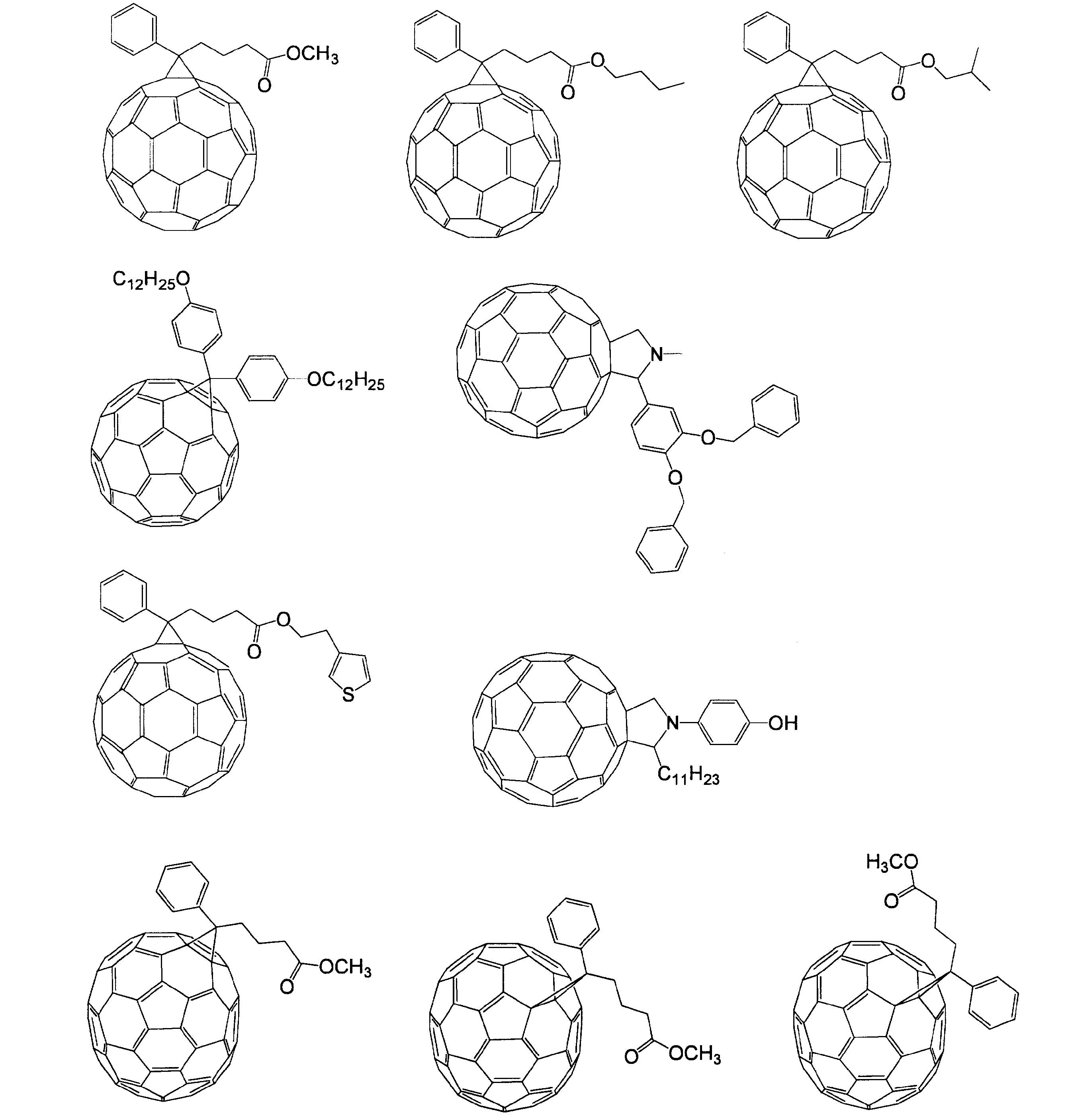
また、フラーレン誘導体の例としては、[6,6]フェニル-C61酪酸メチルエステル(C60PCBM、[6,6]-Phenyl C61 butyric acid methyl ester)、[6,6]フェニル-C71酪酸メチルエステル(C70PCBM、[6,6]-Phenyl C71 butyric acid methyl ester)、[6,6]フェニル-C85酪酸メチルエステル(C84PCBM、[6,6]-Phenyl C85 butyric acid methyl ester)、[6,6]チエニル-C61酪酸メチルエステル([6,6]-Thienyl C61 butyric acid methyl ester)などが挙げられる。
電子受容性化合物としてフラーレン誘導体を用いる場合、フラーレン誘導体の割合が、電子供与性化合物100重量部に対して、10重量部~1000重量部であることが好ましく、20重量部~500重量部であることがより好ましい。
活性層の厚さは、通常、1nm~100μmが好ましく、より好ましくは2nm~1000nmであり、さらに好ましくは5nm~500nmであり、より好ましくは20nm~200nmである。
<活性層の形成方法>
活性層は、如何なる方法で製造してもよく、製造方法の例としては、有機化合物を含む溶液を用いた成膜方法、真空蒸着による成膜方法などが挙げられる。
活性層は、如何なる方法で製造してもよく、製造方法の例としては、有機化合物を含む溶液を用いた成膜方法、真空蒸着による成膜方法などが挙げられる。
溶液からの成膜に用いる溶媒は、活性層の材料を溶解させ得るものを適宜選択してよい。活性層に用いられる有機化合物等を溶解させるための溶媒の例としては、トルエン、キシレン、メシチレン、テトラリン、デカリン、ビシクロヘキシル、ブチルベンゼン、sec-ブチルベンゼン、tert-ブチルベンゼン等の不飽和炭化水素系溶媒、四塩化炭素、クロロホルム、ジクロロメタン、ジクロロエタン、クロロブタン、ブロモブタン、クロロペンタン、ブロモペンタン、クロロヘキサン、ブロモヘキサン、クロロシクロヘキサン、ブロモシクロヘキサン等のハロゲン化飽和炭化水素系溶媒、クロロベンゼン、ジクロロベンゼン、トリクロロベンゼン等のハロゲン化不飽和炭化水素系溶媒、テトラヒドロフラン、テトラヒドロピラン等のエーテル類系溶媒等が挙げられる。
成膜には、スピンコート法、キャスティング法、マイクログラビアコート法、グラビアコート法、バーコート法、ロールコート法、ワイアーバーコート法、ディップコート法、スプレーコート法、スクリーン印刷法、グラビア印刷法、フレキソ印刷法、オフセット印刷法、インクジェット印刷法、ディスペンサー印刷法、ノズルコート法、キャピラリーコート法等の塗布法を用いることができ、スピンコート法、フレキソ印刷法、グラビア印刷法、インクジェット印刷法、ディスペンサー印刷法が好ましい。
<中間層>
光電変換効率を向上させるための手段として活性層以外の付加的な中間層を使用してもよい。中間層は、例えば、光電変換効率を向上させるなどの目的により設けられる。中間層を機能層としてみた場合、中間層の例としては、電荷輸送層(正孔輸送層または電子輸送層)、電荷ブロック層(正孔ブロック層または電子ブロック層)、およびバッファ層などが挙げられる。また、中間層として用いられる材料としては、フッ化リチウム(LiF)等のアルカリ金属、アルカリ土類金属のハロゲン化物、酸化物等を用いることができる。また、酸化チタン等無機半導体の微粒子、PEDOT(ポリ-3,4-エチレンジオキシチオフェン)などが挙げられる。
光電変換効率を向上させるための手段として活性層以外の付加的な中間層を使用してもよい。中間層は、例えば、光電変換効率を向上させるなどの目的により設けられる。中間層を機能層としてみた場合、中間層の例としては、電荷輸送層(正孔輸送層または電子輸送層)、電荷ブロック層(正孔ブロック層または電子ブロック層)、およびバッファ層などが挙げられる。また、中間層として用いられる材料としては、フッ化リチウム(LiF)等のアルカリ金属、アルカリ土類金属のハロゲン化物、酸化物等を用いることができる。また、酸化チタン等無機半導体の微粒子、PEDOT(ポリ-3,4-エチレンジオキシチオフェン)などが挙げられる。
中間層の形成方法に特に制限はなく、その材料の種類や設計される層の厚みなどの条件を勘案し、適宜、様々な薄膜形成方法を選択し得る。層形成原料として溶液を用いる場合は、上記の塗布法などの成膜方法と同様の方法が例示される。その他、真空蒸着法、スパッタリング法、イオンプレーティング法、化学的気相成長法(CVD法)、メッキ法などを採用してもよい。
シート状の有機光電変換素子とした際に円筒状のパイプ本体に巻き付けることができる程度に変形可能であれば、各中間層の厚さは特に限定されないが、好ましくは0.1μm~500μmであり、より好ましくは1μm~100μmである。
<層構成>
まず有機光電変換素子の基本的な層構成について、図3を参照しつつ説明する。図3に示す有効光電変換素子20は、第1電極32と第2電極52で構成される一対の電極と、一対の電極の間に配置された活性層40とを備えている。第1電極32および第2電極52は、いずれか一方が陽極となり、他方が陰極となる。どちらの電極が陽極または陰極となるかは任意に設計し得る。第1電極32と活性層40との間には第1中間層31が設けられている。第2電極52と活性層40との間には第2中間層51が設けられている。図3に示される層構成では、活性層40を単層としているが、上記でも説明したとおり、活性層40は、pnヘテロ接合型の2層からなる構成による活性層としてもよいし、バルクへテロ型の単層の構成による活性層としてもよい。第1中間層31および第2中間層51は任意の層であり、いずれか一方または双方を省略してもよい。また図3に示される層構成では各中間層を単層としているが、各中間層は複数の層により構成してもよい。
まず有機光電変換素子の基本的な層構成について、図3を参照しつつ説明する。図3に示す有効光電変換素子20は、第1電極32と第2電極52で構成される一対の電極と、一対の電極の間に配置された活性層40とを備えている。第1電極32および第2電極52は、いずれか一方が陽極となり、他方が陰極となる。どちらの電極が陽極または陰極となるかは任意に設計し得る。第1電極32と活性層40との間には第1中間層31が設けられている。第2電極52と活性層40との間には第2中間層51が設けられている。図3に示される層構成では、活性層40を単層としているが、上記でも説明したとおり、活性層40は、pnヘテロ接合型の2層からなる構成による活性層としてもよいし、バルクへテロ型の単層の構成による活性層としてもよい。第1中間層31および第2中間層51は任意の層であり、いずれか一方または双方を省略してもよい。また図3に示される層構成では各中間層を単層としているが、各中間層は複数の層により構成してもよい。
有機光電変換素子のとり得る層構成のパターンは、例えば下記a)~h)のように表される。
a)陽極/活性層/陰極
b)陽極/中間層/活性層/陰極
c)陽極/活性層/中間層/陰極
d)陽極/中間層/活性層/中間層/陰極
e)陽極/電子供給性層/電子受容性層/陰極
f)陽極/中間層/電子供給性層/電子受容性層/陰極
g)陽極/電子供給性層/電子受容性層/中間層/陰極
h)陽極/中間層/電子供給性層/電子受容性層/中間層/陰極
(ここで、記号「/」は、記号「/」を挟む層同士が隣接して積層されていることを示す。)
a)陽極/活性層/陰極
b)陽極/中間層/活性層/陰極
c)陽極/活性層/中間層/陰極
d)陽極/中間層/活性層/中間層/陰極
e)陽極/電子供給性層/電子受容性層/陰極
f)陽極/中間層/電子供給性層/電子受容性層/陰極
g)陽極/電子供給性層/電子受容性層/中間層/陰極
h)陽極/中間層/電子供給性層/電子受容性層/中間層/陰極
(ここで、記号「/」は、記号「/」を挟む層同士が隣接して積層されていることを示す。)
上記層構成において「電子供給性層/電子受容性層」はpnヘテロ接合型の活性層を表す。
上記層構成は、陽極がパイプ本体15により近い側に設けられる形態、及び陰極がパイプ本体15により近い側に設けられる形態のいずれであってもよい。
上記層構成は、陽極がパイプ本体15により近い側に設けられる形態、及び陰極がパイプ本体15により近い側に設けられる形態のいずれであってもよい。
上述のとおり、中間層は、様々な機能層であり得る。中間層としては、例えば、電荷輸送層、電荷ブロック層、バッファ層などが挙げられる。中間層が電荷輸送層である場合、陽極と活性層との間に設けられる中間層は、正孔輸送層であり、陰極と活性層との間に設けられる中間層は電子輸送層である。中間層がブロック層である場合、陽極と活性層との間に設けられる中間層は電子ブロック層であり、陰極と活性層との間に設けられる中間層は正孔ブロック層である。
本発明において用いられる有機光電変換素子20は、上記のような層構成のいずれであってもよい。有機光電変換素子20の電極の外側の面(パイプ本体15より遠い側の面)には、必要に応じてさらに封止層、基板などを設け得る。また、シート状の有機光電変換素子20をパイプ本体15の外周面に設けるにあたり、上記のような素子の層構成に加え、さらに他の構成、例えば保護膜、光学フィルムなどを設けてもよい。保護膜、光学フィルムなどを集光層としてさらに設ける場合には、シート状の有機光電変換素子の受光面に接合するように集光層が設け得る。
図4に、第1実施形態として、パイプ15の外周面15aにシート状有機光電変換素子20が貼り付けられたパイプ10の層構成を示す。図4に示すシート状有機光電変換素子20は、パイプ本体15により近い側(図4において下方)からより遠い側(図4において上方)に向かって順に、第1基板35、第1電極32、中間層31、活性層40、第2中間層51、第2電極52、封止層53、第2基板55が積層されて構成されている。シート状有機光電変換素子20は、パイプ本体15の外周面に接着剤によって密着固定されている。図4において、接着剤が介在する部分は、接着層19として表している。
また、第1実施形態の変形例として、例えば、第1基板35のパイプ本体15に対向する面に高伝熱性材料で形成した層(伝熱層)を設け、パイプ本体15への熱伝導性を向上させてもよい。伝熱層を形成する材料としては、例えば、Cu、Ti、Fe、W、Alなどの金属、又はこれらの金属からなるエクスパンドメタルが挙げられる。
第2基板55は受光領域を形成し、光は第2基板55の露出面である受光面55aから活性層40に入射する。
封止層53は、その内側(パイプ本体15により近い側)に設けられた第2電極52や活性層40などの各層を外気から遮断する。封止層53としては、水、酸素などが不透過性の層とすることが好適である。
封止層53は、その内側(パイプ本体15により近い側)に設けられた第2電極52や活性層40などの各層を外気から遮断する。封止層53としては、水、酸素などが不透過性の層とすることが好適である。
第1基板35は、シート状有機光電変換素子20が担う機能に応じて、適宜設計される。図4に示す例において、第1基板35は、パイプ本体15との接着面を提供している。第1基板35を、素子の製造時において、各層を順次積層形成するための支持基板として利用してもよい。シート状有機光電変換素子20を発電器として利用し、かつ、パイプ本体15が導電性の材料で構成される場合には、第1基板35を絶縁性の層としてもよい。また、パイプ本体15に対する熱伝導性を重視する場合には、第1基板35を高熱伝導性の層として設けてもよい。
第2基板55は、シート状有機光電変換素子20の内部を保護する保護層として機能し得る。また、第2基板55は、光学フィルムにより構成されてもよい。例えば、第2基板55として、集光性を有する光学フィルムなどを設け得る。一般に、有機光電変換素子は、無機光電変換素子に比べ、散乱光や輻射光を活性層に集光することによる光の利用効率向上の幅が大きい。本発明では、有機光電変換素子が採用されるため、集光層などの光学フィルムを上記のように設けることは好適な形態となり得る。
シート状有機光電変換素子20とパイプ本体15との接着に用いられる接着剤は、双方の材質等に応じて、適宜選択してよい。また、本発明のパイプは、太陽光などに長時間曝される場所に設置されることが好適であることから、接着層19は熱耐性を有することが好ましい。
<パイプ>
パイプ本体15は、円筒状であること以外には特に制限はない。材料にも特に制限はなく、パイプ本体15内を流れることが予定される流体の種類などの条件に応じて適宜選択してよい。パイプ本体15としては、流体の配管として用いられる様々な部材を利用し得る。パイプ本体15の例としては、金属製パイプ、プラスチック製パイプ、木製パイプなどを挙げることができる。本発明のパイプ10は、パイプ本体15内を流れる流体を昇温する機能を有している。温水システムに本発明のパイプ10を利用することを想定すると、パイプ本体15としては、例えば、プラスチック製の円筒状部材などが好適である。
パイプ本体15は、円筒状であること以外には特に制限はない。材料にも特に制限はなく、パイプ本体15内を流れることが予定される流体の種類などの条件に応じて適宜選択してよい。パイプ本体15としては、流体の配管として用いられる様々な部材を利用し得る。パイプ本体15の例としては、金属製パイプ、プラスチック製パイプ、木製パイプなどを挙げることができる。本発明のパイプ10は、パイプ本体15内を流れる流体を昇温する機能を有している。温水システムに本発明のパイプ10を利用することを想定すると、パイプ本体15としては、例えば、プラスチック製の円筒状部材などが好適である。
2.本発明の第2実施形態(パイプ)
図5を参照して本発明の第2実施形態について説明する。なお、第1実施形態と同じ構成については図面に符合を付け、説明を省略する。第2実施形態では、パイプ本体15と第1電極32とが直接的に接するように層が構成されている。第1電極32は導電性材料で形成される。導電性材料には熱伝導性に優れているものも多い。したがって、パイプ本体15に対し第1電極32を密着させて設けることにより、シート状有機光電変換素子20からの熱をパイプ本体15内を流れる流体により効率よく伝えることができる。すなわち、第1電極32を伝熱層としても利用している。第2実施形態によれば、基板という部材を減らしてコストの低減および製造工程の簡略化が可能であると共に、集熱器としてのシート状有機光電変換素子をより効率的に利用し得る。
図5を参照して本発明の第2実施形態について説明する。なお、第1実施形態と同じ構成については図面に符合を付け、説明を省略する。第2実施形態では、パイプ本体15と第1電極32とが直接的に接するように層が構成されている。第1電極32は導電性材料で形成される。導電性材料には熱伝導性に優れているものも多い。したがって、パイプ本体15に対し第1電極32を密着させて設けることにより、シート状有機光電変換素子20からの熱をパイプ本体15内を流れる流体により効率よく伝えることができる。すなわち、第1電極32を伝熱層としても利用している。第2実施形態によれば、基板という部材を減らしてコストの低減および製造工程の簡略化が可能であると共に、集熱器としてのシート状有機光電変換素子をより効率的に利用し得る。
シート状有機光電変換素子20を集熱器として利用するだけではなく、発電器として利用する場合であって、パイプ本体15が非導電性材料で形成されたものであるとき、パイプ本体15に絶縁体の役割を担わせてもよい。これに対し、シート状有機光電変換素子20を集熱器として利用するだけではなく、発電器として利用する場合であって、パイプ本体15が導電性材料で形成されたものであるときは、配管されたパイプ本体15の一部に絶縁体を設けることが好ましい。
3.本発明の第3実施形態(パイプ)
図6を参照して本発明の第3実施形態について説明する。なお、第1実施形態と同じ構成については図面に符合を付け、説明を省略する。第3実施形態では、パイプ本体15の外周の全周ではなく略半周にシート状光電変換素子20が設けられている。
すなわち、シート状光電有機変換素子は、良好な受光が可能な領域に応じて、パイプ本体15の一部に設けてもよい。
本実施形態のパイプ10は、パイプ本体15の外周面15aのうち、受光する部分のみにシート状有機光電変換素子20を設ける構成とすることができる。また本実施形態のパイプ10は、パイプ本体15の外周面15aのうち、受光する部分のうちの少なくとも一部にシート状有機光電変換素子20が設けられる構成としてもよい。
図6を参照して本発明の第3実施形態について説明する。なお、第1実施形態と同じ構成については図面に符合を付け、説明を省略する。第3実施形態では、パイプ本体15の外周の全周ではなく略半周にシート状光電変換素子20が設けられている。
すなわち、シート状光電有機変換素子は、良好な受光が可能な領域に応じて、パイプ本体15の一部に設けてもよい。
本実施形態のパイプ10は、パイプ本体15の外周面15aのうち、受光する部分のみにシート状有機光電変換素子20を設ける構成とすることができる。また本実施形態のパイプ10は、パイプ本体15の外周面15aのうち、受光する部分のうちの少なくとも一部にシート状有機光電変換素子20が設けられる構成としてもよい。
次に、本発明の温水システムの実施形態について説明する。以下の実施形態は、上記本発明のパイプ10の設置形態でもある。
4.本発明の第4実施形態(温水システム)
図7に本発明の第4実施形態の概要を示す。なお、第1実施形態と同じ構成については図面に符合を付け、説明を省略する。第4実施形態の温水システムでは、貯水槽60と、貯水槽60に連なる配管の一部として上記本発明のパイプ10とが設けられている。図7には、配管の一部を上記本発明のパイプ10とする構成の一例を示したが、配管の全部を上記本発明のパイプ10としてもよい。
パイプ10は、貯水槽60の上流であって、屋外の太陽光を受光可能な場所に設けられている。パイプ10は、貯水槽60への水の供給路であればよく、屋上部に設置されていてもよいし、地上部に設置されていてもよい。受光し得ない部分は、シート状有機光電変換素子20を設けていないパイプ本体15(以下、通常パイプという場合がある。)により配管されている。なお温水システムに用いられるパイプ10は、上記のようにパイプ本体15の外周面15aのうち、受光する部分のみにシート状有機光電変換素子20を設ける構成のみならず、パイプ本体15の外周面15aのうち、受光する部分のうちの少なくとも一部にシート状有機光電変換素子20が設けられる構成としてもよい。また受光し得ない部分を含めた外周面15aの全面にシート状有機光電変換素子20を設ける構成としてもよい(以下の温水システムの実施形態において同様である。)。
第4実施形態によれば、貯水槽60の上流で水を温めることが可能である。
4.本発明の第4実施形態(温水システム)
図7に本発明の第4実施形態の概要を示す。なお、第1実施形態と同じ構成については図面に符合を付け、説明を省略する。第4実施形態の温水システムでは、貯水槽60と、貯水槽60に連なる配管の一部として上記本発明のパイプ10とが設けられている。図7には、配管の一部を上記本発明のパイプ10とする構成の一例を示したが、配管の全部を上記本発明のパイプ10としてもよい。
パイプ10は、貯水槽60の上流であって、屋外の太陽光を受光可能な場所に設けられている。パイプ10は、貯水槽60への水の供給路であればよく、屋上部に設置されていてもよいし、地上部に設置されていてもよい。受光し得ない部分は、シート状有機光電変換素子20を設けていないパイプ本体15(以下、通常パイプという場合がある。)により配管されている。なお温水システムに用いられるパイプ10は、上記のようにパイプ本体15の外周面15aのうち、受光する部分のみにシート状有機光電変換素子20を設ける構成のみならず、パイプ本体15の外周面15aのうち、受光する部分のうちの少なくとも一部にシート状有機光電変換素子20が設けられる構成としてもよい。また受光し得ない部分を含めた外周面15aの全面にシート状有機光電変換素子20を設ける構成としてもよい(以下の温水システムの実施形態において同様である。)。
第4実施形態によれば、貯水槽60の上流で水を温めることが可能である。
貯水槽60は、槽内の水を加温する機能を備える温水器であってもよい。このような温水器としては、例えば、電気温水器が挙げられる。貯水槽60が電気温水器である場合、電気温水器に供給される水の温度が高いため、電気温水器による加温の負荷を減らすことができ、発電所または変電所などからの外部供給電力の節電に寄与する。
また、パイプ10は、シート状有機光電変換素子20により電力を供給することもできる。シート状有機光電変換素子20から供給される電力を電気温水器に供給する電力として利用してもよいし、温水システムが設置される建築物における補助的な電源として利用してもよい。また、シート状有機光電変換素子20が光電変換機能を発揮している際には、シート状有機光電変換素子20の温度上昇を抑制するほうが光電変換効率の観点から好ましい場合がある。パイプ10では、パイプ10内を流れる水とシート状有機光電変換素子20との間で熱交換され、水は加温されて利用され、且つ、シート状有機光電変換素子20は温度上昇が抑制され、好ましい光電変換効率を維持し得るという利点を得ることができる。
5.本発明の第5実施形態(温水システム)
図8に第5実施形態の概要を示す。なお、第4実施形態と同じ構成については図面に符合を付け、説明を省略する。第5実施形態では、太陽熱温水器に連なる配管の一部として、上記本発明のパイプ10を設けている。なお配管の全部を上記本発明のパイプ10としてもよい。
図8に第5実施形態の概要を示す。なお、第4実施形態と同じ構成については図面に符合を付け、説明を省略する。第5実施形態では、太陽熱温水器に連なる配管の一部として、上記本発明のパイプ10を設けている。なお配管の全部を上記本発明のパイプ10としてもよい。
図8に示す太陽熱温水器は、自然循環式の太陽熱温水器であり、貯水槽60と集熱板(太陽熱集熱器)70とを備え、パイプ本体15Uおよびパイプ本体15Dを介して貯水槽60と集熱板70との間を水が循環する。自然循環式の太陽熱温水器では、貯水槽60からパイプ本体15Uを通して集熱板内に水が供給され、集熱板を水が巡回して熱が加えられ、温められた水がパイプ本体15Dを通じて貯水槽60へと戻るというサイクルが、太陽熱を利用した対流により進行する。
貯水槽60には、その上流に連結されたパイプ10Uを通じて水が供給される一方、下流に連結されたパイプ10Dを通じて加温された水(温水)が外部へと配送される。貯水槽60の上流にパイプ10Uが設けられることにより、貯水槽60に供給する水の温度を上げて供給することができ、所望の温度へ加温するために要する時間を短くすることができる。また、貯水槽60の下流にパイプ10Dが設けられることにより、貯水槽60から供給される温水の温度低下を抑制することができる。
自然循環式の太陽熱温水器は、一般に、太陽光の受光が良好な場所、例えば建築物の屋上などに設置される。したがって、自然循環式の太陽熱温水器へ給水する配管および外部への温水を配送する配管に、本発明のパイプ10を用いることにより、太陽光のより有効な利用が可能となる。
6.本発明の第6実施形態(温水システム)
図9に第6実施形態の概要を示す。なお、第5実施形態と同じ構成については図面に符合を付け、説明を省略する。第6実施形態では、強制循環式の太陽熱温水器に連なる配管の一部として、上記本発明のパイプ10を設けている。図9には、配管の一部を上記本発明のパイプ10とする構成の一例を示したが、配管の全部を上記本発明のパイプ10としてもよい。
図9に第6実施形態の概要を示す。なお、第5実施形態と同じ構成については図面に符合を付け、説明を省略する。第6実施形態では、強制循環式の太陽熱温水器に連なる配管の一部として、上記本発明のパイプ10を設けている。図9には、配管の一部を上記本発明のパイプ10とする構成の一例を示したが、配管の全部を上記本発明のパイプ10としてもよい。
強制循環式の太陽熱温水器では、集熱板70において水または不凍液などの流体を利用する。強制循環式の太陽熱温水器では、流体を循環する系を有する。流体を循環させればよいので、貯水槽は集熱板のある屋上などの高い位置に設置する必要性は必ずしもないという利点がある。
図9に示すように、第6実施形態では、流体槽64に貯められている流体がポンプにより集熱板70へと汲み上げられ、集熱板70で加温された流体が、貯水槽(温水器)62に設けられた熱交換部63に配送され、貯水槽62に貯められた水を加温する。貯水槽62には、パイプ本体15Uから水が供給され、パイプ15Dから温水が送り出される。
第6実施形態では、流体を配送するパイプの一部として、集熱板70の上流部にパイプ10Uが設けられ、集熱板70の下流部にパイプ10Dが設けられている。このようにして、集熱板70だけではなく、配管においても流体を加温することができ、太陽光の効率的な利用が図られる。
7.本発明の第7の実施形態(温水システム)
図10に第7実施形態の概要を示す。なお、第5実施形態と同じ構成については図面に符合を付け、説明を省略する。
第7実施形態では、第1貯水槽60Aおよび太陽熱の集熱板70を備えた太陽熱温水器と、第2貯水槽60Bとして電気温水器とを組み合わせた形態である。第1貯水槽60Aおよび集熱板70を備えた太陽熱温水器は、第5実施形態に示したものと同様である。該太陽熱温水器は、例えば建築物の屋上などの場所に設置され、直射日光を受光する。第1貯水槽60Aへの水を給水する配管の一部は、パイプ10U(10)により構成されており、加温された水が第1貯水槽60Aへ供給される。
図10に第7実施形態の概要を示す。なお、第5実施形態と同じ構成については図面に符合を付け、説明を省略する。
第7実施形態では、第1貯水槽60Aおよび太陽熱の集熱板70を備えた太陽熱温水器と、第2貯水槽60Bとして電気温水器とを組み合わせた形態である。第1貯水槽60Aおよび集熱板70を備えた太陽熱温水器は、第5実施形態に示したものと同様である。該太陽熱温水器は、例えば建築物の屋上などの場所に設置され、直射日光を受光する。第1貯水槽60Aへの水を給水する配管の一部は、パイプ10U(10)により構成されており、加温された水が第1貯水槽60Aへ供給される。
第2貯水槽60Bは電気温水器である。第2貯水槽に給水される経路は2系統あり、一方は第1貯水槽60Aから供給され、もう1つは外部水源から供給されている。第1貯水槽60Aと第2貯水槽とを連結する配管の一部はパイプ10D(10)により構成されており、第1貯水槽60Aで加温された温水を加温しつつ、第2貯水槽60Bへ温水を供給することができる。第2貯水槽60Bからはパイプ本体15Dを通じて温水が配送される。第2貯水槽60Bである電気温水器は、第1貯水槽60Aから供給された温水を、再度温めたり、第1貯水槽から供給される温水よりも高い温度にまで上昇させたりすることができる。第1貯水槽60Aから電気温水器に供給される水は、集熱板70やパイプ10Dにて温められた温水であるため、電気温水器による加温の負荷を減らすことができ、発電所または変電所などから供給される外部供給電力の節電に寄与する。
また、パイプ10U、10Dは、シート状有機光電変換素子20により電力を供給することもできるため、シート状有機光電変換素子20から供給される電力を第2貯水槽としての電気温水器に供給する電力として利用することができ、さらに本温水システムが設置される建築物における電力として利用することもできる。このように、太陽熱温水器と電気温水器と、本発明のパイプ10を組み合わせて利用することにより、太陽光の有効利用が可能である。
8.本発明の第8実施形態(温水システム)
図11に第8実施形態の概要を示す。なお、第7実施形態と同じ構成については図面に符合を付け、説明を省略する。
図11に第8実施形態の概要を示す。なお、第7実施形態と同じ構成については図面に符合を付け、説明を省略する。
第8実施形態では、太陽電池モジュール81とこれを冷却する水冷ユニット83を有する太陽光利用ハイブリッド装置80が設けられている。太陽電池モジュール81は複数の有機光電変換素子を集積して構成されている。太陽光利用ハイブリッド装置80は、例えば建築物の屋上などの場所に設置され、直射日光を受光する。太陽電池モジュール81から供給される電力は、本温水システムの設置された建築物や、電気温水器66に供給可能である。
有機光電変換素子をベースとする太陽電池モジュールはその稼働時において温度が高くなるほど光電変換効率が低下する傾向がある。そこで太陽光利用ハイブリッド装置80では水冷ユニット83を設け、太陽電池モジュール81を冷却している。水冷ユニット83は、パイプ本体15U1を通じて外部から水が供給される。水冷ユニット83に供給される水は太陽電池モジュール81の水冷に用いるので、パイプ本体15U1は上記本発明の昇温パイプを用いず、通常パイプにより構成されている。水冷ユニット83内は、該ユニット83内を水が巡回するように配管されており、この配管内を水が通過し、太陽電池モジュール81から生じる熱を吸収する。このようにして太陽電池モジュール81は冷却される。熱を吸収した水は、水冷ユニット83から電気温水器66へと送られる。水冷ユニット83と電気温水器66とを結ぶ配管には、パイプ10D(10)が設けられている。そのため水冷ユニット83で熱を吸収した水をさらに加温しながら電気温水器66へと給水することができる。
このように、太陽電池モジュール81における水冷ユニット83とパイプ10Dとを経由して電気温水器64に給水する系を設けることにより、電気温水器66における加温の負荷を軽減することができる。
このように、太陽電池モジュール81における水冷ユニット83とパイプ10Dとを経由して電気温水器64に給水する系を設けることにより、電気温水器66における加温の負荷を軽減することができる。
また、パイプ10Dは、シート状有機光電変換素子20により電力を供給することもできるため、シート状有機光電変換素子20から供給される電力を電気温水器66に供給する電力として利用してもよいし、或いは、温水システムが設置される建築物における電力として利用することもできる。このように、太陽電池モジュール81およびこれを冷却する水冷ユニット83を有する太陽光利用ハイブリッド装置80とパイプ10Dとを組み合わせて使用することにより、多岐にわたり太陽光の有効利用が可能である。
実施例1(有機光電変換素子の作成)
スパッタ法により約150nmの膜厚のITO膜を成膜したPEN(ポリエチレンナフタレート)フィルム(基板)のITO膜をパターニングして、有機溶媒、アルカリ洗剤、超純水で洗浄し、乾燥させた。このパターニングされたITO膜を備えたPENフィルムに、UV-O3装置にてUV-O3処理を行った。
スパッタ法により約150nmの膜厚のITO膜を成膜したPEN(ポリエチレンナフタレート)フィルム(基板)のITO膜をパターニングして、有機溶媒、アルカリ洗剤、超純水で洗浄し、乾燥させた。このパターニングされたITO膜を備えたPENフィルムに、UV-O3装置にてUV-O3処理を行った。
次に、電子供与性高分子材料としてのP3HTと[5,6]-フェニル C61 ブチリックアシッドメチルエステル([5,6]-PCBM)との重量比1:0.8のオルトジクロロベンゼン溶液を調製した。P3HTの添加量は、オルトジクロロベンゼンに対して1重量%とした。その後0.2μm径のフィルターでろ過を行った。得られた溶液をスピンコートした後、N2雰囲気中で乾燥を行って活性層を形成した。
形成された活性層の上部に、抵抗加熱蒸着装置内にて、LiF膜を約2.3nm、続いてAl膜を約70nmの膜厚で成膜して、電極を形成した。さらに封止材としてエポキシ樹脂(急速硬化型アラルダイト)にてさらなるPENフィルムを接着することで封止処理を施し、フィルム状の有機薄膜太陽電池(有機光電変換素子)を得た。
さらに流水パイプ(内部に流水を通してあるパイプ本体)に銅箔を介してフィルム状の有機薄膜太陽電池を貼り付けた。
さらに流水パイプ(内部に流水を通してあるパイプ本体)に銅箔を介してフィルム状の有機薄膜太陽電池を貼り付けた。
実施例2(有機光電変換素子の作成)
スパッタ法により約150nmの膜厚のITO膜を成膜したPENフィルムのITO膜をパターニングして、有機溶媒、アルカリ洗剤、超純水で洗浄し、乾燥させた。このパターニングされたITO膜を備えたPENフィルムに、UV-O3装置にてUV-O3処理を行った。
スパッタ法により約150nmの膜厚のITO膜を成膜したPENフィルムのITO膜をパターニングして、有機溶媒、アルカリ洗剤、超純水で洗浄し、乾燥させた。このパターニングされたITO膜を備えたPENフィルムに、UV-O3装置にてUV-O3処理を行った。
次に、高分子化合物Aと[5,6]-フェニル C61 ブチリックアシッドメチルエステル([5,6]-PCBM)との重量比1:2のオルトジクロロベンゼン溶液を調製した。高分子化合物Aの添加量は、オルトジクロロベンゼンに対して0.5重量%とした。高分子化合物Aは、ポリスチレン換算の重量平均分子量が17000であり、ポリスチレン換算の数平均分子量が5000であった。重合体Aの光吸収端波長は925nmであった。
その後0.2μm径のフィルターで上記オルトジクロロベンゼン溶液のろ過を行った。得られた溶液をスピンコートした後、N2雰囲気中で乾燥を行って活性層を形成した。
形成された活性層の上部に、抵抗加熱蒸着装置内にて、LiF膜を約2.3nm、続いてAl膜を約70nmの膜厚で成膜して、電極を形成した。さらに封止材としてエポキシ樹脂(急速硬化型アラルダイト)にてさらなるPENフィルムを接着することで封止処理を施し、フィルム状の有機薄膜太陽電池を得た。更に流水パイプに銅箔を介してフィルム状の有機薄膜太陽電池を貼り付けた。
実施例3(有機光電変換素子の作成)
スパッタ法により約150nmの膜厚のITO膜を成膜したPENフィルムのITO膜をパターニングして、有機溶媒、アルカリ洗剤、超純水で洗浄し、乾燥させた。このパターニングされたITO膜を備えたPENフィルムに、UV-O3装置にてUV-O3処理を行った。
スパッタ法により約150nmの膜厚のITO膜を成膜したPENフィルムのITO膜をパターニングして、有機溶媒、アルカリ洗剤、超純水で洗浄し、乾燥させた。このパターニングされたITO膜を備えたPENフィルムに、UV-O3装置にてUV-O3処理を行った。
次に、電子供与性高分子材料としての高分子化合物Bと[5,6]-フェニル C61 ブチリックアシッドメチルエステル([5,6]-PCBM)の重量比1:3のオルトジクロロベンゼン溶液を調製した。高分子化合物Bの添加量は、オルトジクロロベンゼン溶液に対して0.5重量%とした。その後0.2μm径のフィルターでろ過を行った。得られた溶液をスピンコートした後、N2雰囲気中で乾燥を行って活性層を形成した。
形成された活性層の上部に、抵抗加熱蒸着装置内にて、LiF膜を約2.3nm、続いてAl膜を約70nmの膜厚で成膜し、電極を形成した。さらに封止材としてエポキシ樹脂(急速硬化型アラルダイト)にてさらなるPENフィルムを接着することで封止処理を施し、フィルム状の有機薄膜太陽電池を得た。
さらに流水パイプに銅箔を介してフィルム状の有機薄膜太陽電池を貼り付けた。
さらに流水パイプに銅箔を介してフィルム状の有機薄膜太陽電池を貼り付けた。
比較例1から比較例3は実施例1から実施例3と同様の手法により作製したフィルム状の有機薄膜太陽電池を銅箔を介して内部に流水を通さないパイプに貼り付けた。
(光電変換効率の評価)
実施例及び比較例において得られたフィルム状の有機薄膜太陽電池を貼り付けたパイプ(昇温パイプ)に、作製直後の有機薄膜太陽電池特性に対する30分後と60分後の光電変換効率保持率を測定した。特性測定はソーラシミュレーター(分光計器製、商品名:CEP-2000型、放射照度100mW/cm2)を用いて一定の光を照射し、発生する電流と電圧を測定し、光電変換効率を算出した。効率保持率は30分経過後、60分経過後に測定した光電変換効率を作製直後の光電変換効率で除して算出した。なお保持場所は屋外に日照下とした。結果を表1に示す。
実施例及び比較例において得られたフィルム状の有機薄膜太陽電池を貼り付けたパイプ(昇温パイプ)に、作製直後の有機薄膜太陽電池特性に対する30分後と60分後の光電変換効率保持率を測定した。特性測定はソーラシミュレーター(分光計器製、商品名:CEP-2000型、放射照度100mW/cm2)を用いて一定の光を照射し、発生する電流と電圧を測定し、光電変換効率を算出した。効率保持率は30分経過後、60分経過後に測定した光電変換効率を作製直後の光電変換効率で除して算出した。なお保持場所は屋外に日照下とした。結果を表1に示す。
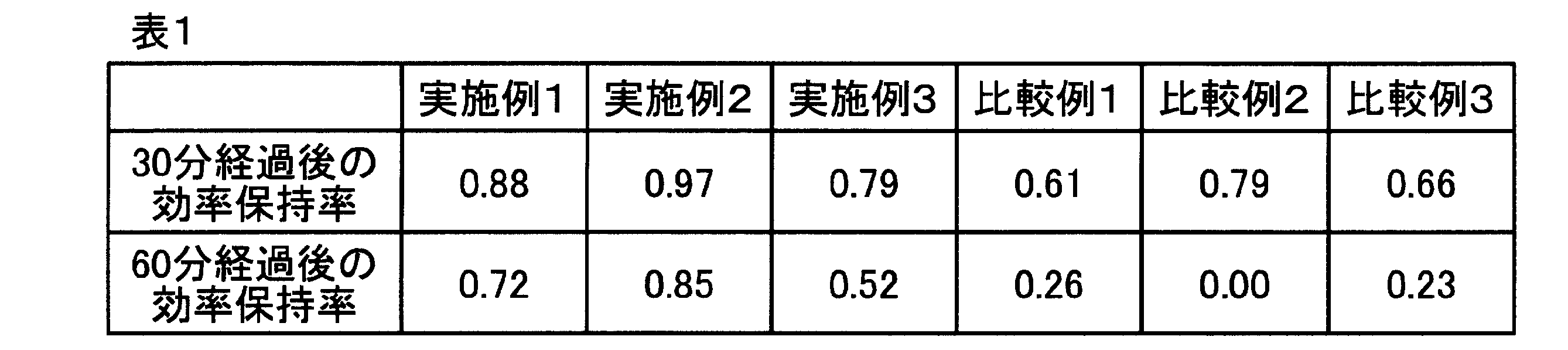
表1から明らかなように、実施例1から実施例3の有機薄膜太陽電池の効率保持率は、比較例1から比較例3の有機薄膜太陽電池の効率保持率よりも高かった。すなわち実施例1から実施例3の有機薄膜太陽電池は、より高い耐久性を有していた。なお比較例2の60分後の有機薄膜太陽電池はフィルムの熱膨張による剥離で破損していた。
本発明のパイプは、流体に熱を加えて昇温する機能を有することから、温水システム等に利用でき、太陽エネルギーの有効利用を図ることができる。
Claims (11)
- 円筒状のパイプ本体と、該パイプ本体の外周面に設けられたシート状の有機光電変換素子とを具備する、パイプ。
- 前記有機光電変換素子の受光面に、集光層がさらに設けられている、請求項1に記載のパイプ。
- 前記有機光電変換素子と前記パイプ本体の外周面との間に伝熱層が設けられている、請求項1に記載のパイプ。
- 請求項1に記載のパイプを備える温水システム。
- 貯水槽と、太陽熱集熱器と、配管とを備える温水システムであって、
前記配管のうちの一部又は全部が、請求項1に記載のパイプにより構成されている温水システム。 - 流体を加温する太陽熱集熱器と、前記流体と水との間で熱交換を行う熱交換部を有する貯水槽と、前記太陽熱集熱器と前記貯水槽との間で流体を循環させる循環ポンプと、前記流体を配送する配管とを備え、
前記流体を配送する配管のうちの一部又は全部が、請求項1に記載のパイプにより構成されている温水システム。 - 電気温水器と太陽電池モジュールと配管とを備える温水システムであって、
前記配管のうちの一部又は全部が、請求項1に記載のパイプにより構成されており、
前記太陽光発電モジュールおよび前記パイプの双方またはいずれか一方が、前記電熱温水器に電力供給可能なように電気的に接続されている、温水システム。 - 前記太陽光発電モジュールに生じる熱を吸収し該太陽光発電モジュールを冷却する水を巡回させる水冷ユニットを備え、前記太陽発電モジュールから熱を吸収した水が前記電気温水器に供給されるように接続された配管を備える、請求項7に記載の温水システム。
- 前記水冷ユニットから前記電気温水器に至る配管のうちの一部又は全部が、請求項1に記載のパイプにより構成されている、請求項8に記載の温水システム。
- 請求項1に記載のパイプを備える建築物。
- 請求項1に記載のパイプの昇温器のための使用。
Applications Claiming Priority (2)
| Application Number | Priority Date | Filing Date | Title |
|---|---|---|---|
| JP2009-250769 | 2009-10-30 | ||
| JP2009250769 | 2009-10-30 |
Publications (1)
| Publication Number | Publication Date |
|---|---|
| WO2011052508A1 true WO2011052508A1 (ja) | 2011-05-05 |
Family
ID=43921930
Family Applications (1)
| Application Number | Title | Priority Date | Filing Date |
|---|---|---|---|
| PCT/JP2010/068731 Ceased WO2011052508A1 (ja) | 2009-10-30 | 2010-10-22 | パイプ及び該パイプを備えた温水システム |
Country Status (2)
| Country | Link |
|---|---|
| JP (1) | JP2011117597A (ja) |
| WO (1) | WO2011052508A1 (ja) |
Cited By (4)
| Publication number | Priority date | Publication date | Assignee | Title |
|---|---|---|---|---|
| CN106979431A (zh) * | 2017-05-12 | 2017-07-25 | 成都大漠石油技术有限公司 | 利用太阳能发电提高原油运输能力的机构 |
| CN107120495A (zh) * | 2017-05-12 | 2017-09-01 | 成都大漠石油技术有限公司 | 适用于野外原油输送管道的支撑装置 |
| EP2828898B1 (en) * | 2012-08-10 | 2017-10-04 | Dimerond Technologies, LLC | Apparatus including solar cells having nanowire titanium oxide or silicon carbide cores and graphene shells, and use thereof |
| CN107246526A (zh) * | 2017-07-21 | 2017-10-13 | 四川达灿石油设备有限公司 | 可防止石油管道凝结的连接结构 |
Families Citing this family (7)
| Publication number | Priority date | Publication date | Assignee | Title |
|---|---|---|---|---|
| JP5585918B2 (ja) * | 2011-10-06 | 2014-09-10 | 輝彰 奥西 | 給湯効果付き太陽熱発電器 |
| JP6401369B1 (ja) * | 2017-10-23 | 2018-10-10 | 櫻護謨株式会社 | 電源を備えた送水ホース及び媒介ユニット |
| JP7166850B2 (ja) * | 2018-09-06 | 2022-11-08 | 櫻護謨株式会社 | 電源を備えた送水ホース及び媒介ユニット |
| CN114623605B (zh) * | 2020-12-14 | 2023-08-22 | 清华大学 | 太阳能集热器及太阳能热水器 |
| CN114689180B (zh) | 2020-12-14 | 2025-11-28 | 清华大学 | 红外探测器及红外成像仪 |
| CN114621621A (zh) | 2020-12-14 | 2022-06-14 | 清华大学 | 光吸收体预制液及其制备方法 |
| CN114622405A (zh) | 2020-12-14 | 2022-06-14 | 清华大学 | 红外隐身布料及红外隐身服装 |
Citations (6)
| Publication number | Priority date | Publication date | Assignee | Title |
|---|---|---|---|---|
| JPS56168059A (en) * | 1980-05-28 | 1981-12-24 | Fuji Electric Co Ltd | System for power generation and collecting heat by solar beams |
| JPH07127913A (ja) * | 1993-11-06 | 1995-05-19 | Yupatsuku:Kk | 節電型即熱式給湯装置 |
| JP2006284069A (ja) * | 2005-03-31 | 2006-10-19 | Daiwa House Ind Co Ltd | 太陽熱集熱器を用いたソーラーシステム |
| JP2007134440A (ja) * | 2005-11-09 | 2007-05-31 | Kyocera Corp | 光電変換装置 |
| JP2008270577A (ja) * | 2007-04-21 | 2008-11-06 | Toshihiko Sakurai | 太陽電池を利用した太陽光発電システム |
| JP2009252768A (ja) * | 2008-04-01 | 2009-10-29 | Fuji Electric Holdings Co Ltd | 有機太陽電池、およびその製造方法 |
Family Cites Families (3)
| Publication number | Priority date | Publication date | Assignee | Title |
|---|---|---|---|---|
| JPH0979662A (ja) * | 1995-09-18 | 1997-03-28 | Fujita Corp | 太陽光エネルギの取り出し方法及び太陽電池パネル一体型温水器 |
| JPH10325618A (ja) * | 1997-03-26 | 1998-12-08 | Sekisui Chem Co Ltd | 給湯装置 |
| JP5228422B2 (ja) * | 2006-09-29 | 2013-07-03 | 大日本印刷株式会社 | 光電変換層用塗工液およびその製造方法ならびに、有機薄膜太陽電池およびその製造方法 |
-
2010
- 2010-10-22 WO PCT/JP2010/068731 patent/WO2011052508A1/ja not_active Ceased
- 2010-10-28 JP JP2010242381A patent/JP2011117597A/ja active Pending
Patent Citations (6)
| Publication number | Priority date | Publication date | Assignee | Title |
|---|---|---|---|---|
| JPS56168059A (en) * | 1980-05-28 | 1981-12-24 | Fuji Electric Co Ltd | System for power generation and collecting heat by solar beams |
| JPH07127913A (ja) * | 1993-11-06 | 1995-05-19 | Yupatsuku:Kk | 節電型即熱式給湯装置 |
| JP2006284069A (ja) * | 2005-03-31 | 2006-10-19 | Daiwa House Ind Co Ltd | 太陽熱集熱器を用いたソーラーシステム |
| JP2007134440A (ja) * | 2005-11-09 | 2007-05-31 | Kyocera Corp | 光電変換装置 |
| JP2008270577A (ja) * | 2007-04-21 | 2008-11-06 | Toshihiko Sakurai | 太陽電池を利用した太陽光発電システム |
| JP2009252768A (ja) * | 2008-04-01 | 2009-10-29 | Fuji Electric Holdings Co Ltd | 有機太陽電池、およびその製造方法 |
Cited By (4)
| Publication number | Priority date | Publication date | Assignee | Title |
|---|---|---|---|---|
| EP2828898B1 (en) * | 2012-08-10 | 2017-10-04 | Dimerond Technologies, LLC | Apparatus including solar cells having nanowire titanium oxide or silicon carbide cores and graphene shells, and use thereof |
| CN106979431A (zh) * | 2017-05-12 | 2017-07-25 | 成都大漠石油技术有限公司 | 利用太阳能发电提高原油运输能力的机构 |
| CN107120495A (zh) * | 2017-05-12 | 2017-09-01 | 成都大漠石油技术有限公司 | 适用于野外原油输送管道的支撑装置 |
| CN107246526A (zh) * | 2017-07-21 | 2017-10-13 | 四川达灿石油设备有限公司 | 可防止石油管道凝结的连接结构 |
Also Published As
| Publication number | Publication date |
|---|---|
| JP2011117597A (ja) | 2011-06-16 |
Similar Documents
| Publication | Publication Date | Title |
|---|---|---|
| WO2011052508A1 (ja) | パイプ及び該パイプを備えた温水システム | |
| JP5553727B2 (ja) | 有機光電変換素子及びその製造方法 | |
| JP5300903B2 (ja) | ポリマーおよびそれを用いた太陽電池、太陽光発電システム | |
| US20100224252A1 (en) | Photovoltaic Cell Having Multiple Electron Donors | |
| CN102598337B (zh) | 有机光电转换元件 | |
| JP5603912B2 (ja) | 太陽電池モジュール | |
| JP5537636B2 (ja) | 太陽電池及び太陽電池モジュール | |
| JP2014053383A (ja) | タンデム型の有機光電変換素子およびこれを用いた太陽電池 | |
| US20120199201A1 (en) | Organic thin film solar cell and manufacturing method thereof | |
| US20120211741A1 (en) | Organic photovoltaic cell | |
| CN102132437A (zh) | 有机光电转换元件及其制造方法 | |
| JP2010062550A (ja) | 光電変換素子 | |
| JPWO2010090123A1 (ja) | 有機光電変換素子、それを用いた太陽電池、及び光センサアレイ | |
| JP5553728B2 (ja) | 有機光電変換素子 | |
| WO2011052577A1 (ja) | 有機光電変換素子及びその製造方法 | |
| JP5608040B2 (ja) | 有機光電変換素子 | |
| Kwon et al. | Vacuum processable donor material based on dithieno [3, 2-b: 2′, 3′-d] thiophene and pyrene for efficient organic solar cells | |
| JP2015183032A (ja) | 縮環系シクロペンタジチオフェン骨格を有するポリマー及びそれを用いた有機薄膜太陽電池材料 | |
| CN102576808A (zh) | 有机光电转换元件及其制造方法 | |
| KR101714949B1 (ko) | 반도체 중합체 | |
| JP2010251235A (ja) | 電子素子 |
Legal Events
| Date | Code | Title | Description |
|---|---|---|---|
| 121 | Ep: the epo has been informed by wipo that ep was designated in this application |
Ref document number: 10826640 Country of ref document: EP Kind code of ref document: A1 |
|
| NENP | Non-entry into the national phase |
Ref country code: DE |
|
| 122 | Ep: pct application non-entry in european phase |
Ref document number: 10826640 Country of ref document: EP Kind code of ref document: A1 |