WO2011052055A1 - 空気調和装置 - Google Patents
空気調和装置 Download PDFInfo
- Publication number
- WO2011052055A1 WO2011052055A1 PCT/JP2009/068554 JP2009068554W WO2011052055A1 WO 2011052055 A1 WO2011052055 A1 WO 2011052055A1 JP 2009068554 W JP2009068554 W JP 2009068554W WO 2011052055 A1 WO2011052055 A1 WO 2011052055A1
- Authority
- WO
- WIPO (PCT)
- Prior art keywords
- refrigerant
- unit
- heat medium
- heat
- relay unit
- Prior art date
Links
Images


Classifications
-
- F—MECHANICAL ENGINEERING; LIGHTING; HEATING; WEAPONS; BLASTING
- F24—HEATING; RANGES; VENTILATING
- F24F—AIR-CONDITIONING; AIR-HUMIDIFICATION; VENTILATION; USE OF AIR CURRENTS FOR SCREENING
- F24F3/00—Air-conditioning systems in which conditioned primary air is supplied from one or more central stations to distributing units in the rooms or spaces where it may receive secondary treatment; Apparatus specially designed for such systems
- F24F3/06—Air-conditioning systems in which conditioned primary air is supplied from one or more central stations to distributing units in the rooms or spaces where it may receive secondary treatment; Apparatus specially designed for such systems characterised by the arrangements for the supply of heat-exchange fluid for the subsequent treatment of primary air in the room units
- F24F3/065—Air-conditioning systems in which conditioned primary air is supplied from one or more central stations to distributing units in the rooms or spaces where it may receive secondary treatment; Apparatus specially designed for such systems characterised by the arrangements for the supply of heat-exchange fluid for the subsequent treatment of primary air in the room units with a plurality of evaporators or condensers
-
- F—MECHANICAL ENGINEERING; LIGHTING; HEATING; WEAPONS; BLASTING
- F25—REFRIGERATION OR COOLING; COMBINED HEATING AND REFRIGERATION SYSTEMS; HEAT PUMP SYSTEMS; MANUFACTURE OR STORAGE OF ICE; LIQUEFACTION SOLIDIFICATION OF GASES
- F25B—REFRIGERATION MACHINES, PLANTS OR SYSTEMS; COMBINED HEATING AND REFRIGERATION SYSTEMS; HEAT PUMP SYSTEMS
- F25B13/00—Compression machines, plants or systems, with reversible cycle
-
- F—MECHANICAL ENGINEERING; LIGHTING; HEATING; WEAPONS; BLASTING
- F25—REFRIGERATION OR COOLING; COMBINED HEATING AND REFRIGERATION SYSTEMS; HEAT PUMP SYSTEMS; MANUFACTURE OR STORAGE OF ICE; LIQUEFACTION SOLIDIFICATION OF GASES
- F25B—REFRIGERATION MACHINES, PLANTS OR SYSTEMS; COMBINED HEATING AND REFRIGERATION SYSTEMS; HEAT PUMP SYSTEMS
- F25B2313/00—Compression machines, plants or systems with reversible cycle not otherwise provided for
- F25B2313/003—Indoor unit with water as a heat sink or heat source
-
- F—MECHANICAL ENGINEERING; LIGHTING; HEATING; WEAPONS; BLASTING
- F25—REFRIGERATION OR COOLING; COMBINED HEATING AND REFRIGERATION SYSTEMS; HEAT PUMP SYSTEMS; MANUFACTURE OR STORAGE OF ICE; LIQUEFACTION SOLIDIFICATION OF GASES
- F25B—REFRIGERATION MACHINES, PLANTS OR SYSTEMS; COMBINED HEATING AND REFRIGERATION SYSTEMS; HEAT PUMP SYSTEMS
- F25B2313/00—Compression machines, plants or systems with reversible cycle not otherwise provided for
- F25B2313/006—Compression machines, plants or systems with reversible cycle not otherwise provided for two pipes connecting the outdoor side to the indoor side with multiple indoor units
-
- F—MECHANICAL ENGINEERING; LIGHTING; HEATING; WEAPONS; BLASTING
- F25—REFRIGERATION OR COOLING; COMBINED HEATING AND REFRIGERATION SYSTEMS; HEAT PUMP SYSTEMS; MANUFACTURE OR STORAGE OF ICE; LIQUEFACTION SOLIDIFICATION OF GASES
- F25B—REFRIGERATION MACHINES, PLANTS OR SYSTEMS; COMBINED HEATING AND REFRIGERATION SYSTEMS; HEAT PUMP SYSTEMS
- F25B2313/00—Compression machines, plants or systems with reversible cycle not otherwise provided for
- F25B2313/007—Compression machines, plants or systems with reversible cycle not otherwise provided for three pipes connecting the outdoor side to the indoor side with multiple indoor units
-
- F—MECHANICAL ENGINEERING; LIGHTING; HEATING; WEAPONS; BLASTING
- F25—REFRIGERATION OR COOLING; COMBINED HEATING AND REFRIGERATION SYSTEMS; HEAT PUMP SYSTEMS; MANUFACTURE OR STORAGE OF ICE; LIQUEFACTION SOLIDIFICATION OF GASES
- F25B—REFRIGERATION MACHINES, PLANTS OR SYSTEMS; COMBINED HEATING AND REFRIGERATION SYSTEMS; HEAT PUMP SYSTEMS
- F25B2313/00—Compression machines, plants or systems with reversible cycle not otherwise provided for
- F25B2313/023—Compression machines, plants or systems with reversible cycle not otherwise provided for using multiple indoor units
- F25B2313/0231—Compression machines, plants or systems with reversible cycle not otherwise provided for using multiple indoor units with simultaneous cooling and heating
-
- F—MECHANICAL ENGINEERING; LIGHTING; HEATING; WEAPONS; BLASTING
- F25—REFRIGERATION OR COOLING; COMBINED HEATING AND REFRIGERATION SYSTEMS; HEAT PUMP SYSTEMS; MANUFACTURE OR STORAGE OF ICE; LIQUEFACTION SOLIDIFICATION OF GASES
- F25B—REFRIGERATION MACHINES, PLANTS OR SYSTEMS; COMBINED HEATING AND REFRIGERATION SYSTEMS; HEAT PUMP SYSTEMS
- F25B2313/00—Compression machines, plants or systems with reversible cycle not otherwise provided for
- F25B2313/027—Compression machines, plants or systems with reversible cycle not otherwise provided for characterised by the reversing means
- F25B2313/0272—Compression machines, plants or systems with reversible cycle not otherwise provided for characterised by the reversing means using bridge circuits of one-way valves
-
- F—MECHANICAL ENGINEERING; LIGHTING; HEATING; WEAPONS; BLASTING
- F25—REFRIGERATION OR COOLING; COMBINED HEATING AND REFRIGERATION SYSTEMS; HEAT PUMP SYSTEMS; MANUFACTURE OR STORAGE OF ICE; LIQUEFACTION SOLIDIFICATION OF GASES
- F25B—REFRIGERATION MACHINES, PLANTS OR SYSTEMS; COMBINED HEATING AND REFRIGERATION SYSTEMS; HEAT PUMP SYSTEMS
- F25B2313/00—Compression machines, plants or systems with reversible cycle not otherwise provided for
- F25B2313/027—Compression machines, plants or systems with reversible cycle not otherwise provided for characterised by the reversing means
- F25B2313/02732—Compression machines, plants or systems with reversible cycle not otherwise provided for characterised by the reversing means using two three-way valves
-
- F—MECHANICAL ENGINEERING; LIGHTING; HEATING; WEAPONS; BLASTING
- F25—REFRIGERATION OR COOLING; COMBINED HEATING AND REFRIGERATION SYSTEMS; HEAT PUMP SYSTEMS; MANUFACTURE OR STORAGE OF ICE; LIQUEFACTION SOLIDIFICATION OF GASES
- F25B—REFRIGERATION MACHINES, PLANTS OR SYSTEMS; COMBINED HEATING AND REFRIGERATION SYSTEMS; HEAT PUMP SYSTEMS
- F25B2313/00—Compression machines, plants or systems with reversible cycle not otherwise provided for
- F25B2313/027—Compression machines, plants or systems with reversible cycle not otherwise provided for characterised by the reversing means
- F25B2313/02743—Compression machines, plants or systems with reversible cycle not otherwise provided for characterised by the reversing means using three four-way valves
-
- F—MECHANICAL ENGINEERING; LIGHTING; HEATING; WEAPONS; BLASTING
- F25—REFRIGERATION OR COOLING; COMBINED HEATING AND REFRIGERATION SYSTEMS; HEAT PUMP SYSTEMS; MANUFACTURE OR STORAGE OF ICE; LIQUEFACTION SOLIDIFICATION OF GASES
- F25B—REFRIGERATION MACHINES, PLANTS OR SYSTEMS; COMBINED HEATING AND REFRIGERATION SYSTEMS; HEAT PUMP SYSTEMS
- F25B2400/00—General features or devices for refrigeration machines, plants or systems, combined heating and refrigeration systems or heat-pump systems, i.e. not limited to a particular subgroup of F25B
- F25B2400/23—Separators
-
- F—MECHANICAL ENGINEERING; LIGHTING; HEATING; WEAPONS; BLASTING
- F25—REFRIGERATION OR COOLING; COMBINED HEATING AND REFRIGERATION SYSTEMS; HEAT PUMP SYSTEMS; MANUFACTURE OR STORAGE OF ICE; LIQUEFACTION SOLIDIFICATION OF GASES
- F25B—REFRIGERATION MACHINES, PLANTS OR SYSTEMS; COMBINED HEATING AND REFRIGERATION SYSTEMS; HEAT PUMP SYSTEMS
- F25B25/00—Machines, plants or systems, using a combination of modes of operation covered by two or more of the groups F25B1/00 - F25B23/00
- F25B25/005—Machines, plants or systems, using a combination of modes of operation covered by two or more of the groups F25B1/00 - F25B23/00 using primary and secondary systems
Definitions
- the present invention relates to an air conditioner used for, for example, a building multi-air conditioner that efficiently supplies hot and cold produced by a heat source machine or both hot and cold to a plurality of loads.
- a conventional air conditioner in a building multi-air conditioner or the like uses, for example, an HFC (hydrofluorocarbon) -based refrigerant by compression heating or reduced-pressure cooling using a heat source device such as an outdoor unit disposed outside the room. Then, the refrigerant is conveyed to an indoor unit disposed in a room connected to the outdoor unit by an extension pipe, and the refrigerant absorbs heat by exchanging heat with indoor air by the indoor unit, so that the refrigerant dissipates heat. By doing so, the heating operation is carried out.
- HFC hydrofluorocarbon
- a heat source such as water or antifreeze liquid that is transported into the outdoor unit by using a heat source device such as an outdoor unit is heated or cooled, and the heat medium is connected to the outdoor unit by an extension pipe or heat radiation heat absorption.
- a chiller system that performs cooling operation or heating operation by supplying the apparatus. For example, see Patent Documents 1 to 4.
- Japanese Patent Laying-Open No. 2005-140444 page 4, FIG. 1, etc.
- JP-A-5-280818 (4th, 5th page, FIG. 1 etc.)
- Japanese Patent Laid-Open No. 2001-289465 pages 5 to 8, FIG. 1, FIG. 2, etc.
- JP 2003-343936 A (Page 5, FIG. 1)
- a cooling operation or a heating operation is performed by supplying and circulating a refrigerant heated or cooled from a heat source unit of an outdoor unit to an indoor unit. Therefore, when refrigerant leakage occurs in an indoor unit, there is a possibility that the total amount of refrigerant required by all indoor units connected to the outdoor unit may leak from the leakage location to the room where the indoor unit is located. there were.
- a refrigerant heated or cooled from a heat source unit of an outdoor unit is temporarily used as an indoor unit cooling refrigerant or an indoor unit heating refrigerant by an outdoor-indoor relay unit.
- Some outdoor-indoor relay units can be connected in parallel at the same time.
- the total amount of refrigerant according to the number of outdoor-indoor relay units and indoor units connected to the outdoor unit is required, and when refrigerant leakage occurs, the total amount of refrigerant leaks into the room from the leak location. There is a possibility that.
- the outdoor unit In a chiller system that performs heating or cooling operation by heating or cooling a heat medium such as water or antifreeze liquid by a heat source unit in the outdoor unit and then transporting it to the indoor unit using a heat medium transport device, the outdoor unit When a plurality of indoor units are connected to a place far away from the vehicle, a large amount of power is required to transport the heated or cooled heat medium to the indoor units. For this reason, compared with the conventional air conditioning apparatuses, such as a building multi air-conditioner which performs a cooling operation and a heating operation by conveying a refrigerant
- the present invention implements a heating operation or a cooling operation by transporting a heat medium such as water or antifreeze liquid to an indoor unit, avoids refrigerant leakage on the indoor side, and further reduces air transportation power compared to the conventional one. Get the device. Moreover, the air conditioning apparatus which can connect the number of indoor units equivalent to the former is obtained.
- the air conditioner according to this invention is An outdoor unit having a compressor that pressurizes and conveys the refrigerant, a first refrigerant flow switching device that switches a conveyance flow path of the refrigerant, and a heat source side heat exchanger that exchanges heat between the air and the refrigerant; A plurality of indoor units having a use side heat exchanger through which a heat medium flows and heat exchange between the heat medium and air; A relay unit that is interposed between the outdoor unit and the indoor unit, and performs heat exchange between the refrigerant transported from the outdoor unit and the heat medium;
- the relay unit is A main relay unit having at least one main unit throttle device for adjusting the pressure of the refrigerant, and connected to the outdoor unit by a refrigerant pipe; A plurality of inter-heat medium heat exchangers for exchanging heat between the refrigerant and the heat medium; a plurality of second refrigerant flow switching devices for switching the flow paths of the refrigerant conveyed from the main relay unit; A plurality
- the outdoor unit and the main relay unit are connected by two pipes, and the main relay unit and the sub relay unit are connected by three pipes.
- An air conditioner according to the present invention exchanges heat between a refrigerant and a heat medium such as water or antifreeze via a sub-relay unit without directly circulating the refrigerant in a room where the indoor unit is installed, and the heat medium.
- the cooling operation and the heating operation are realized by conveying the air to the indoor unit. For this reason, even if refrigerant leakage occurs, it is possible to avoid refrigerant leakage into the room.
- the sub relay unit can be installed at an appropriate position, and the transport distance of the heat medium can be shortened. Thereby, the motive power by heat carrier conveying apparatuses, such as a pump, can be reduced and energy saving can be aimed at.
- the refrigerant can be separated into gas and liquid and conveyed to the sub-relay unit, and either a gas or liquid refrigerant can be supplied to the plurality of sub-relay units. Can also be supplied.
- each sub-relay unit is adapted to the total load of each sub-relay unit so that each sub-relay unit exchanges heat between the heat medium and the refrigerant according to the load of the indoor unit connected to it.
- the outdoor unit can be operated in the cooling operation mode or the heating operation mode. Thereby, air-conditioning mixed operation can be performed regarding the some indoor unit connected to each sub relay unit.
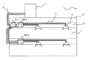
- FIG. 1 is an overall view of an air conditioner according to an embodiment of the present invention, and is a system configuration diagram when a plurality of indoor units are connected.
- FIG. It is a system circuit diagram at the time of all heating operation among the system circuit diagrams of the air conditioning apparatus in embodiment of this invention. It is a system circuit figure at the time of a cooling operation among the system circuit diagrams of the air conditioning apparatus in embodiment of this invention. It is a system circuit diagram at the time of cooling main operation among system circuit diagrams of an air harmony device in an embodiment of this invention. It is a system circuit diagram at the time of heating main operation among the system circuit diagrams of the air conditioning apparatus in embodiment of this invention.
- FIG. 1 is an overall view of an air conditioner according to an embodiment of the present invention, and is a system configuration diagram when a plurality of indoor units are connected.
- the heat source unit (or outdoor unit) 1 and the indoor unit 3 are connected via one main relay unit 2a and a plurality of sub-relay units 2b-1 and 2b-2.
- the sub relay units 2b-1 and 2b-2 are also simply referred to as a relay unit 2b.
- the main relay unit 2 a is installed in a common space or a ceiling or the like in a building such as a building, and the main relay unit 2 a is connected to the outdoor unit 1 using the refrigerant pipe 4.
- a plurality of sub-relay units 2b-1 and 2b-2 are installed in a common space such as a building or a space such as a ceiling, and are connected to the main relay unit 2a by the refrigerant pipe 4.
- the sub-relay unit is not limited to installation for each floor, but is installed according to the number of indoor units to be connected so that it can cope with the load of the indoor space where air conditioning is performed.
- These sub relay units 2 b-1 and 2 b-2 are connected to the indoor unit 3 by being connected to a heat medium pipe 5 through which a heat medium such as water or antifreeze liquid flows.
- the refrigerant is conveyed from the outdoor unit 1 to the main relay unit 2a through the refrigerant pipe 4, separated into gas and liquid by the main relay unit 2a, and then to the plurality of sub relay units 2b-1, 2b-2 through the refrigerant pipe 4. Be transported.
- the conveyed refrigerant exchanges heat between the refrigerant and a heat medium such as water or antifreeze in a heat exchanger between heat mediums (described later) in the sub-relay units 2b-1 and 2b-2 to produce hot water or cold water. It is.
- Hot water or cold water produced by the sub-relay units 2b-1 and 2b-2 is transported to the indoor unit 3 through the heat medium pipe 5 by the heat medium transport device, and the indoor unit 7 performs heating operation on the indoor space 7 Or it is used for cooling operation.
- the sub relay unit 2b is installed in a building or the like as shown in FIG. Multiple installations can be made at different floors in the building. Therefore, the sub relay unit 2b can be installed so that the indoor unit 3 can be installed within the allowable transfer range of the heat medium transfer device provided in the sub relay unit 2b. Further, as shown in FIG. 1, the refrigerant transported from the outdoor unit 1 is separated into gas and liquid by the main relay unit 2a and then transported to the sub relay unit 2b. On the other hand, a refrigerant necessary as a load can be simultaneously supplied.
- the exhaust heat obtained from one sub relay unit 2b-1 can be supplied to the other sub relay unit 2b-2. Furthermore, by simultaneously supplying hot water and cold water from the sub relay unit 2b to the indoor unit 3, heating operation and cooling operation can be performed simultaneously in the plurality of indoor units 3.
- refrigerant on the heat source side examples include single refrigerants such as R-22 and R-134a, pseudo-azeotropic mixed refrigerants such as R-410A and R-404A, non-azeotropic mixed refrigerants such as R-407C, A refrigerant containing a double bond and having a relatively low global warming coefficient such as CF 3 CF ⁇ CH 2 , a mixture thereof, or a natural refrigerant such as CO 2 or propane can be used.
- the heat medium for example, water, antifreeze, a mixture of water and antifreeze, a mixture of water and an additive having a high anticorrosive effect, or the like can be used.
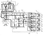
- FIG. 2 is a system circuit diagram (refrigerant circuit diagram) showing an example of an air conditioner according to an embodiment of the present invention. The operation of this air conditioner will be described with reference to FIG.
- the outdoor unit 1 and the main relay unit 2a are connected by the refrigerant pipe 4, and the main relay unit 2a and the sub relay unit 2b-1 are heat exchangers 25a and 25b provided in the sub relay unit 2b-1. It is connected by refrigerant piping 4 via. Further, the sub relay unit 2b-1 and the indoor unit 3 are connected by the heat medium pipe 5 via the heat exchangers 25a and 25b provided in the sub relay unit 2b-1.
- the outdoor unit 1 includes a compressor 10 for compressing the refrigerant to a high temperature and a high pressure and transporting the refrigerant into the refrigerant path, and a four-way valve for switching the operation mode of the outdoor unit 1 according to the heating operation mode and the cooling operation mode.
- the first refrigerant flow switching device 11 such as the above and the heat source side heat exchanger 12 functioning as an evaporator during heating operation and as a condenser during cooling operation are configured as basic elements.
- each of the above elements is connected in series by the refrigerant pipe 4.
- the outdoor unit 1 is provided with refrigerant connection pipes 4a and 4b and check valves 13a, 13b, 13c and 13d for allowing a refrigerant flow only in one direction.
- the main relay unit 2a and the sub relay unit 2b can be connected regardless of the operation mode of the indoor unit 3. It becomes possible to fix the flow of the flowing refrigerant in one direction.
- the indoor unit 3 is equipped with usage-side heat exchangers 35 (35a to 35d).
- the usage-side heat exchanger 35 is installed in the sub relay unit 2b by a heat medium pipe 5 through which a heat medium such as water or antifreeze liquid flows.
- the heat medium flow control device 34 (34a to 34d) and the heat medium flow switching device 33 (33a to 33d) are connected.
- the use side heat exchanger 35 circulates the heat medium supplied from the sub-relay unit 2b-1, and in the indoor unit 3, between air supplied from a blower such as a fan (not shown) and the heat medium. Heat exchange is performed, and heating air or cooling air is supplied to the indoor space 7.
- FIG. 2 four indoor units 3 are connected to the sub-relay unit 2b, and four use-side heat exchangers 35 are connected to each indoor unit 3. Is not limited to four, and may be determined as appropriate.
- the main relay unit 2a takes in the refrigerant conveyed from the outdoor unit 1 and separates it into gas and liquid and sends it out, and a refrigerant return for returning the refrigerant returned from the sub-relay unit 2b to the outdoor unit 1. And a flow path.
- the flow path through which the gas refrigerant separated by the gas-liquid separator 21 flows is the main unit first refrigerant flow path 41, and the liquid refrigerant separated by the gas-liquid separator 21 is the main unit expansion device (first The flow path flowing through the expansion device 22) is referred to as a main unit second refrigerant flow path 42, and the flow path through which the return refrigerant from the sub relay unit 2b-1 flows is referred to as a main unit third refrigerant flow path 43.
- the main unit second refrigerant flow path 42 and the main unit third refrigerant flow path 43 are connected by a main unit bypass flow path 44 via another main unit expansion device (second expansion device 23).
- a first pressure detection device 45a and a second pressure detection device 45b used for control are installed before and after the first throttle device 22 in the main relay unit 2a.
- the sub relay unit 2b includes two or more heat exchangers for heat medium 25 (here, 25a and 25b).
- the heat exchanger related to heat medium 25 exchanges heat between the refrigerant on the heat source side and the heat medium on the use side, and transmits the cold or warm heat generated in the outdoor unit 1 and stored in the refrigerant on the heat source side to the heat medium.
- the inter-heat-medium heat exchanger 25 serves as a condenser (radiator) when supplying the heat medium to the indoor unit 3 in the heating operation, and serves as a condenser (radiator) when supplying the heat medium to the indoor unit 3 in the cooling operation. It functions as an evaporator.
- the heat exchanger related to heat medium 25a is provided between the third refrigerant throttling device 26a and the second refrigerant flow switching device 28a.
- the heat exchanger 25a generates heat during the all-cooling operation and the mixed cooling / heating operation mode. It is used for cooling the medium.
- the heat exchanger related to heat medium 25b is provided between the third refrigerant expansion device 26b and the second refrigerant flow switching device 28b, and is in the all heating operation mode and the cooling / heating mixed operation mode. It is used for heating a heat medium.
- the third refrigerant throttling device 26a and the third refrigerant throttling device 26b are preferably capable of variably controlling the opening of, for example, an electronic expansion valve.
- a four-way valve or the like is used for the second refrigerant flow switching device 28a and the second refrigerant flow switching device 28b, and heat exchange between heat media is performed according to the operation mode of the indoor unit 3 (3a to 3d).
- the refrigerant flow paths are switched so that the containers 25a and 25b function as condensers or evaporators.
- the second refrigerant flow switching device 28a is downstream of the heat exchanger related to heat medium 25a during the cooling operation
- the second refrigerant flow switching device 28b is downstream of the heat exchanger related to heat medium 25b during the cooling operation.
- the second refrigerant flow switching devices 28 a and 28 b are connected to the main unit first refrigerant flow channel 41 and the refrigerant return flow channel of the main unit third refrigerant flow channel 43 so as to be switchable.
- the opposite sides of the third refrigerant expansion devices 26a, 26b to the heat exchangers 25a, 25b are connected to the main unit second refrigerant flow path 42.
- the sub-unit first refrigerant flow path 51 and the third throttling devices 26a and 26b are the main flow paths connecting the second refrigerant flow switching devices 28a and 28b to the main unit first refrigerant flow path 41.
- a flow path communicating with the unit second refrigerant flow path 42 is a subunit second refrigerant flow path 52, and a refrigerant return flow path through which the refrigerant returning to the main relay unit 2a flows is a subunit third refrigerant flow path 53, respectively. Called.
- the subunit second refrigerant flow path 52 and the subunit third refrigerant flow path 53 are connected by the subunit bypass flow path 54 via the fourth expansion device 29.
- a throttle device that controls the opening area of the flow path may be used, or an open / close device that opens and closes the flow path may be used.
- the fourth throttle device 29 is a throttle device, the subunit bypass flow between the subunit second refrigerant flow path 52 and the subunit third refrigerant flow path 53 is controlled by controlling the opening degree according to the operating state.
- the amount of refrigerant flowing through the passage 54 can be adjusted, and finer control can be performed than in the case of using an opening / closing device.
- the sub relay unit 2b has a heat medium flow switching device 32 (32a to 32d) including a three-way valve for each indoor unit 3 (3a to 3d), and A heat medium flow switching device 33 (33a to 33d) is installed.
- the heat medium flow switching device 32 one of the three sides is the heat exchanger 25a, one of the three is the heat exchanger 25b, and one of the three is the heat medium flow controller.
- 34 is provided on the outlet side of the heat medium flow path of the use side heat exchanger 35.
- one of the three sides is the heat exchanger 25a, one of the three is the heat exchanger 25b, and one of the three is the use side heat exchanger 35.
- the heat medium flow control device 34 adjusts the amount of the heat medium flowing into the indoor unit 3 by detecting the temperature of the heat medium flowing into the indoor unit 3 and the temperature of the heat medium flowing out, and is optimal for the indoor load. The amount of heat medium can be provided.
- the heat medium flow control device 34 is provided between the use side heat exchanger 35 and the heat medium flow switching device 32 in FIG. It may be provided between them.
- the heat medium supply to the indoor unit 3 is stopped by fully closing the heat medium flow control device 34. be able to.
- the heat medium transport devices 31 (31a, 31b) corresponding to the heat exchangers 25a, 25b between the heat media. ) Is provided.
- the heat medium transport device 31 is, for example, a pump, and is provided in the heat medium pipe 5 between the heat exchangers 25a and 25b between the heat medium and the heat medium flow switching device 33, and the load of the indoor unit 3 is required.
- the flow rate of the heat medium can be adjusted depending on the size.
- One sub relay unit 2 b is installed for one main relay unit 2 a, and four indoor units 3 are installed in the sub relay unit 2 b.
- coolant and heat medium for every operation mode at the time of doing is shown.
- one or more sub-relay units 2b can be connected to one main relay unit 2a.
- the indoor unit 3 connected with respect to the sub relay unit 2b is not limited to four units.
- the operation of the refrigerant and heat medium in each operation mode is shown below.
- the operation mode in the air conditioner is a heating only operation mode in which all of the driven indoor units 3 perform a heating operation, and a cooling operation in which all of the driven indoor units 3 perform a cooling operation.
- the mixed operation mode in which the cooling operation and the heating operation are mixed on the indoor unit 3 side the cooling main operation mode in which the load of the indoor unit performing the cooling operation is large, the cooling is performed on the indoor unit 3 side.
- FIG. 2 shows the heating only operation mode
- FIG. 3 shows the cooling only operation mode
- FIG. 4 shows the cooling main operation mode
- FIG. 5 shows the refrigerant and heat medium operations in the heating main operation mode.
- FIG. 2 shows the flow of the refrigerant when the air conditioner is in the heating only operation mode.
- a circuit indicated by a thick line in the refrigerant circuit in FIG. 2 is the flow of the refrigerant in the heating only operation mode.
- the flow direction of the heat source side refrigerant is indicated by solid arrows, and the flow direction of the heat medium is indicated by broken arrows.
- the low-temperature and low-pressure refrigerant flows into the compressor 10 and is discharged as a high-temperature and high-pressure gaseous refrigerant.
- the discharged high-temperature and high-pressure refrigerant passes through the first refrigerant flow switching device 11 and the check valve 13a in the outdoor unit 1, passes through the refrigerant pipe 4, and flows into the main relay unit 2a.
- the first refrigerant flow switching device 11 carries the high-temperature and high-pressure gaseous refrigerant discharged from the compressor 10 out of the outdoor unit 1 without passing through the heat source side heat exchanger 12 in the outdoor unit 1. It has been switched as follows.
- the gaseous refrigerant flowing into the main relay unit 2a passes through the gas side in the gas-liquid separator 21 and is carried out to the sub-relay unit 2b, where the second refrigerant flow path switching in the sub-relay unit 2b-1 is performed. It branches and flows into apparatus 28a, 28b. At this time, the opening of the first expansion device 22 is closed, and the opening of the second expansion device 23 is controlled so that the second pressure detection device 45b has a constant pressure, and the second refrigerant flow switching device 28a, 28b has switched to the heating side.
- the gaseous refrigerants that have passed through the second refrigerant flow switching devices 28a and 28b respectively exchange heat with a heat medium such as water or antifreeze liquid by passing through the heat exchangers 25a and 25b.
- the refrigerant that has exchanged heat with the heat medium and has become a high-temperature and high-pressure liquid refrigerant is expanded by passing through the third expansion devices 26a and 26b, and becomes a medium-pressure liquid refrigerant.
- the medium-pressure liquid refrigerant that has passed through the third expansion devices 26a and 26b merges and then flows into the main relay unit 2a. At this time, the fourth diaphragm device 29 is fully closed and the diaphragm function is not performed.
- the opening / closing device When an opening / closing device is used as the fourth expansion device 29, the opening / closing device is closed in the heating only operation mode.
- the medium-pressure liquid refrigerant flowing into the main relay unit 2a passes through the second throttle device 23 to become a two-phase refrigerant in which gas and liquid are mixed at a low temperature and low pressure, and passes through the refrigerant pipe 4 to the outdoor unit 1. Be transported.
- the low-temperature and low-pressure refrigerant conveyed to the outdoor unit 1 passes through the check valve 13b and flows into the heat source side heat exchanger 12 and exchanges heat with the outdoor space 6 to become low-temperature and low-pressure gaseous refrigerant.
- a heat medium such as water or antifreeze liquid exchanges heat with a high-temperature and high-pressure gaseous refrigerant in the heat exchangers 25a and 25b, and becomes a high-temperature heat medium.
- the heat medium heated to a high temperature by the heat exchangers 25a and 25b is transferred to the indoor unit 3 by the heat transfer devices 31a and 31b connected to the heat exchangers 25a and 25b, respectively.
- the transported heat medium passes through the heat medium flow switching device (inlet side) 33 connected to each indoor unit 3, and the heat medium flow rate adjusting device 34 adjusts the flow rate of the heat medium flowing into each indoor unit 3. Is done.
- the heat medium flow switching device 33 has an intermediate opening degree so that the heat medium conveyed from both the heat exchangers 25a and 25b can be supplied to the heat medium flow control device 34 and the indoor unit 3, or The degree of opening is adjusted according to the heat medium temperature at the outlets of the heat exchangers 25a and 25b.
- the heat medium flowing into the indoor unit 3 connected by the heat medium pipe 5 performs a heating operation by exchanging heat with the indoor air in the indoor space 7 by the use side heat exchanger 35.
- the heat medium exchanged by the use-side heat exchanger 35 is conveyed into the sub relay unit 2b through the heat medium pipe 5 and the heat medium flow control device 34.
- the transported heat medium flows into the heat exchangers 25a and 25b through the heat medium flow switching device (exit side) 32 and is supplied to the indoor space 7 through the indoor unit 3 from the refrigerant side. It is received and transported again to the heat medium transport devices 32a and 31b.
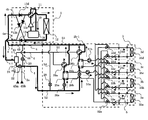
- FIG. 3 shows the refrigerant flow when the air-conditioning apparatus is in the cooling only operation mode.
- a circuit indicated by a thick line in the refrigerant circuit in FIG. 3 is a refrigerant flow in the cooling only operation mode.
- the flow direction of the heat source side refrigerant is indicated by solid arrows, and the flow direction of the heat medium is indicated by broken arrows.
- the low-temperature and low-pressure refrigerant flows into the compressor 10 and is discharged as a high-temperature and high-pressure gaseous refrigerant.
- the discharged high-temperature and high-pressure refrigerant passes through the first refrigerant flow switching device 11 in the outdoor unit 1 and is heat-exchanged by the heat source side heat exchanger 12 in the outdoor unit 1 to be a high-temperature and high-pressure liquid refrigerant. To be taken.
- the first refrigerant flow switching device 11 is switched so that the high-temperature and high-pressure gaseous refrigerant discharged from the compressor 10 passes through the heat source side heat exchanger 12 in the outdoor unit 1.
- the high-temperature and high-pressure liquid refrigerant passes through the check valve 13a, passes through the refrigerant pipe 4, and flows into the main relay unit 2a.
- the high-temperature and high-pressure liquid refrigerant that has flowed into the main relay unit 2a passes through the liquid side in the gas-liquid separator 21 and is carried out to the sub-relay unit 2b.
- the opening degree of the first throttling device 22 is controlled so that the second pressure detecting device 45b has a constant pressure, and the high-temperature and high-pressure liquid refrigerant is changed to a medium-pressure liquid refrigerant, and then sent to the sub-relay unit 2b. And carry out the refrigerant.
- the refrigerant is expanded by passing through the third expansion devices 26a and 26b installed on the upstream side of the heat exchangers 25a and 25b between the heat mediums in the sub-relay unit 2b.
- the two-phase refrigerant At this time, the second expansion device 23 is fully closed, and the second refrigerant flow switching devices 28a and 28b are switched to the cooling side.
- the refrigerant which has become a low-temperature and low-pressure two-phase refrigerant, passes through the heat exchangers 25a and 25b between the heat mediums to exchange heat with a heat medium such as water or antifreeze and becomes a low-temperature and low-pressure gaseous refrigerant.
- the low-temperature and low-pressure gaseous refrigerant passes through the second refrigerant flow switching devices 28 a and 28 b, then passes through the main relay unit 2 a, and is directly conveyed to the outdoor unit 1 through the refrigerant pipe 4.
- the fourth diaphragm device 29 is fully closed.
- the fourth expansion device 29 may be an open / close device, and the open / close device is closed in the cooling only operation mode.
- the low-temperature and low-pressure refrigerant conveyed to the outdoor unit 1 passes through the check valve 13d, is guided into the accumulator 19 by the first refrigerant flow switching device 11, and then returned to the compressor 10.
- the heat medium such as water or antifreeze liquid is cooled to a low temperature by the heat exchangers 25a and 25b, and the heat medium transport device 31a connected to each of the heat exchangers 25a and 25b. It is conveyed to the indoor unit 3 side by 31b.
- the transported heat medium passes through the heat medium flow switching device (inlet side) 33 connected to each indoor unit 3, and the heat medium flow rate adjusting device 34 adjusts the flow rate of the heat medium flowing into each indoor unit 3. Is done.
- the heat medium flow switching device 33 has an intermediate opening degree or heat so that the heat medium conveyed from both the heat exchangers 25a and 25b can be supplied to the heat medium flow control device 34 and the indoor unit 3.
- the opening degree is adjusted according to the heat medium temperature at the outlets of the heat exchangers 25a and 25b.
- the heat medium flowing into the indoor unit 3 connected by the heat medium pipe 5 performs a cooling operation by exchanging heat with the indoor air in the indoor space 7 by the use side heat exchanger 35.
- the heat medium exchanged by the use-side heat exchanger 35 is conveyed into the sub relay unit 2b through the heat medium pipe 5 and the heat medium flow control device 34.
- the transported heat medium flows into each of the heat exchangers 25a and 25b through the heat medium flow switching device (exit side) 32, and the amount of heat received from the indoor space 7 through the indoor unit 3 is the refrigerant side. Then, the temperature is lowered and then transported again by the heat medium transport devices 31a and 31b.
- FIG. 4 shows the refrigerant flow in the cooling main operation mode of the air conditioner.
- a circuit indicated by a thick line in the refrigerant circuit in FIG. 4 is a refrigerant flow in the cooling main operation mode.
- the flow direction of the heat source side refrigerant is indicated by solid arrows, and the flow direction of the heat medium is indicated by broken arrows.
- the low-temperature and low-pressure refrigerant flows into the compressor 10 and is discharged as a high-temperature and high-pressure gaseous refrigerant.
- the discharged high-temperature and high-pressure refrigerant passes through the first refrigerant flow switching device 11 in the outdoor unit 1, and the heating operation in the indoor unit 3 among the heat capacity of the refrigerant by the heat source side heat exchanger 12. Except for the amount required by the indoor unit 3 in the mode, heat is exchanged to form a high-temperature and high-pressure gas or gas or liquid two-phase refrigerant.
- the first refrigerant flow switching device 11 is switched so that the high-temperature and high-pressure gaseous refrigerant discharged from the compressor 10 passes through the heat source side heat exchanger 12 in the outdoor unit 1.
- the high-temperature and high-pressure gas or the two-phase refrigerant passes through the check valve 13a, passes through the refrigerant pipe 4, and flows into the main relay unit 2a.
- the high-temperature and high-pressure gas or two-phase refrigerant that has flowed into the main relay unit 2a is divided into a gas refrigerant and a liquid refrigerant in the gas-liquid separator 21, and is carried out to the sub-relay unit 2b.
- the first throttling device 22 maintains a constant pressure difference based on the pressure difference between the first pressure detecting device 45a which is the pressure at its inlet and the second pressure detecting device 45b which is the pressure at the outlet. Adjusted to possible opening.
- the second diaphragm device 23 is fully closed.
- the second refrigerant flow switching devices 28a and 28b in the sub relay unit 2b the second refrigerant flow switching device 28a is switched to the cooling side, and the second refrigerant flow switching device 28b is switched to the heating side.
- the gaseous refrigerant that has passed through the second refrigerant flow switching device 28b and has flowed into the sub relay unit 2b flows into the heat exchanger related to heat medium 25b.
- the high-temperature and high-pressure gas or two-phase refrigerant that has flowed into the heat exchanger related to heat medium 25b gives heat to the heat medium such as water and antifreeze that is also flowing into the heat exchanger related to heat medium 25b, and the high-temperature and high-pressure liquid. It becomes.
- the refrigerant that has become a high-temperature and high-pressure liquid is expanded by passing through the third expansion device 26b, and becomes a medium-pressure two-phase refrigerant.
- the third expansion device 26b is controlled so that the degree of supercooling of the outlet refrigerant of the heat exchanger related to heat medium 25b becomes a target value.
- the refrigerant that has become the medium-pressure two-phase refrigerant passes through the third expansion device 26a, becomes a low-temperature and low-pressure refrigerant, and flows into the heat exchanger related to heat medium 25a.
- the refrigerant receives heat from a heat medium such as water or antifreeze that is flowing into the heat exchanger 25a, and internally exchanges heat with a heat medium such as water or antifreeze. It becomes a gaseous refrigerant.
- the third expansion device 26a that passes at this time is controlled so that the degree of superheat of the refrigerant after the heat exchange that has passed through the heat exchanger related to heat medium 25a becomes a target value.
- the fourth diaphragm device 29 is fully closed.
- the low-temperature and low-pressure gaseous refrigerant passes through the second refrigerant flow switching device 28a, then passes through the main relay unit 2a, and is directly conveyed to the outdoor unit 1 through the refrigerant pipe 4.
- the low-temperature and low-pressure refrigerant conveyed to the outdoor unit 1 passes through the check valve 13d, is guided into the accumulator 19 by the first refrigerant flow switching device 11, and then returned to the compressor 10.
- the heat medium having a low temperature in the heat exchanger related to heat medium 25a is heated in the heat exchanger related to heat medium 25b by the heat medium conveying device 31a connected to the heat exchanger related to heat medium 25a.
- the heat medium having a high temperature is conveyed by a heat medium conveying device 31b connected to the heat exchanger related to heat medium 25b.
- the transported heat medium passes through the heat medium flow switching device (inlet side) 33 connected to each indoor unit 3, and the heat medium flow rate adjusting device 34 adjusts the flow rate of the heat medium flowing into each indoor unit 3. Is done.
- the heat medium flow switching device 33 is switched to the direction in which the heat exchanger related to heat medium 25b and the heat medium transport device 31b are connected.
- the indoor unit 3 is switched to the direction in which the heat exchanger related to heat medium 25a and the heat medium transfer device 31a are connected.
- the heat medium supplied to the indoor unit 3 can be switched to hot water or cold water depending on the operation mode of the indoor unit 3.
- the heat medium that has flowed into the indoor unit 3 connected by the heat medium pipe 5 performs a heating operation or a cooling operation by exchanging heat with the indoor air in the indoor space 7 by the use side heat exchanger 35.
- the heat medium exchanged by the use-side heat exchanger 35 passes through the heat medium pipe 5 and the heat medium flow control device 34 and is conveyed into the sub relay unit 2b.
- the conveyed heat medium flows into the heat medium flow switching device (exit side) 32.
- the heat medium flow switching device 32 switches to the direction in which the heat exchanger related to heat medium 25b is connected, and the connected indoor unit 3 performs the cooling operation.
- the direction is switched to the direction connected to the heat exchanger related to heat medium 25a.
- the heat medium used in the heating operation mode receives heat from the refrigerant as a heating application
- the heat medium used in the cooling operation mode receives heat from the heat medium heat exchanger 25b.
- the heat exchanger 25a is appropriately flown into the heat exchanger 25a, and each heat exchanges with the refrigerant again, and is then transferred to the heat transfer devices 31a and 31b.
- FIG. 5 is a system circuit diagram showing a refrigerant flow in the heating main operation mode of the air conditioner.
- a circuit indicated by a thick line in the refrigerant circuit in FIG. 5 is a refrigerant flow in the heating main operation mode.
- the flow direction of the heat source side refrigerant is indicated by solid arrows, and the flow direction of the heat medium is indicated by broken arrows.
- the low-temperature and low-pressure refrigerant flows into the compressor 10 and is discharged as a high-temperature and high-pressure gaseous refrigerant.
- the discharged high-temperature and high-pressure refrigerant passes through the first refrigerant flow switching device 11 and the check valve 13c in the outdoor unit 1, passes through the refrigerant pipe 4, and flows into the main relay unit 2a.
- the first refrigerant flow switching device 11 carries the high-temperature and high-pressure gaseous refrigerant discharged from the compressor 10 out of the outdoor unit 1 without passing through the heat source side heat exchanger 12 in the outdoor unit 1. It has been switched as follows.
- the high-temperature and high-pressure gaseous refrigerant flowing into the main relay unit 2a passes through the gas side in the gas-liquid separator 21 and is carried out to the sub-relay unit 2b. It passes through the device 28b and flows into the heat exchanger related to heat medium 25b. At this time, the first expansion device 22 is closed, and the second expansion device 23 controls the opening degree so that the second pressure detection device 45b has a constant pressure.
- the second refrigerant flow switching devices 28a and 28b in the sub-relay unit 2b-1 the second refrigerant flow switching device 28a is on the cooling side, and the second refrigerant flow switching device 28b is on the heating side. Switching.
- the high-temperature and high-pressure gaseous refrigerant that has flowed into the sub relay unit 2b-1 and passed through the second refrigerant flow switching device 28b flows into the heat exchanger related to heat medium 25b, and also flows into the heat exchanger related to heat medium 25b. Heat is given to the heat medium such as water and antifreeze, and it becomes a high-temperature and high-pressure liquid.
- the refrigerant that has become a high-temperature and high-pressure liquid is expanded by passing through the third expansion device 26b, and becomes a medium-pressure two-phase refrigerant. At this time, the third expansion device 26b is controlled so that the degree of supercooling of the outlet refrigerant of the heat exchanger related to heat medium 25b becomes a target value.
- the refrigerant that has become the medium-pressure two-phase refrigerant passes through the third expansion device 26a, becomes a low-temperature and low-pressure refrigerant, and flows into the heat exchanger related to heat medium 25a.
- the refrigerant similarly receives heat from a heat medium such as water or antifreeze flowing into the heat exchanger related to heat medium 25a.
- the third expansion device 26a that passes at this time is controlled so that the degree of superheat of the refrigerant after the heat exchange that has passed through the heat exchanger related to heat medium 25a becomes a target value.
- the refrigerant that has passed through the second refrigerant flow switching device 28a passes through the main relay unit 2a and is directly conveyed to the outdoor unit 1 through the refrigerant pipe 4.
- the fourth diaphragm device 29 is fully closed.
- the low-temperature and low-pressure two-phase refrigerant conveyed to the outdoor unit 1 passes through the check valve 13b and passes through the heat source side heat exchanger 12 to exchange heat with the outdoor space 6 to become a low-temperature and low-pressure gaseous refrigerant.
- the first refrigerant flow switching device 11 it is returned to the compressor 10.
- the heat medium such as water or antifreeze liquid is transferred to the heat medium transport device 31a connected to the heat exchanger 25a.
- the heat medium heated to a high temperature in the intermediate heat exchanger 25b is conveyed by the heat medium conveying device 31b connected to the intermediate heat exchanger 25b.
- the transported heat medium passes through the heat medium flow switching device (inlet side) 33 connected to each indoor unit 3, and the heat medium flow rate adjusting device 34 adjusts the flow rate of the heat medium flowing into each indoor unit 3. Is done.
- the heat medium flow switching device 33 is switched to the direction in which the heat exchanger related to heat medium 25b and the heat medium transport device 31b are connected.
- the indoor unit 3 is switched to the direction in which the heat exchanger related to heat medium 25a and the heat medium transfer device 31a are connected.
- the heat medium supplied to the indoor unit 3 can be switched to hot water or cold water depending on the operation mode of the indoor unit 3.
- the heat medium that has flowed into the indoor units connected by the heat medium pipe 5 performs a heating operation or a cooling operation by exchanging heat with the indoor air in the indoor space 7 by the use side heat exchanger 35.
- the heat medium exchanged by the use-side heat exchanger 35 passes through the heat medium pipe 5 and the heat medium flow control device 34 and is conveyed into the sub relay unit 2b.
- the conveyed heat medium flows into the heat medium flow switching device (exit side) 32.
- the heat medium flow switching device 32 switches to the direction in which the heat exchanger related to heat medium 25b is connected, and the connected indoor unit 3 is cooled.
- the direction is switched to the direction connected to the heat exchanger related to heat medium 25a.
- the heat medium used in the heating operation mode receives heat from the refrigerant as a heating application
- the heat medium used in the cooling operation mode receives heat from the heat medium heat exchanger 25b.
- the heat exchanger 25a is inflowing into the heat exchanger 25a, and each exchanges heat with the refrigerant again, and is then transferred to the heat transfer devices 31a and 31b.
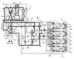
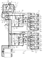
- 6, 7, 8, and 9 are refrigerant circuit configuration diagrams showing other embodiments of the present invention.
- 6 to 9 the refrigerant for each operation mode when a plurality of sub-relay units 2b are connected to one main relay unit 2a and four indoor units 3 are installed for each sub-relay unit 2b.
- the operation mode in this air conditioner is connected to all the sub-relay units 2b connected to the main relay unit 2a, and is the all-heating operation mode in which all the indoor units 3 that are driven are performing the heating operation, There is a cooling only operation mode in which all the driven indoor units 3 are performing a cooling operation.
- the cooling operation having a large load ratio in the cooling operation mode as a ratio of the total operation load.
- the main unit operation mode and the indoor unit 3 are performing the cooling operation and the heating operation, there is a heating main operation mode in which the ratio of the load in the heating operation mode is large as the ratio of the total operation load.
- 6 shows the operation of the refrigerant and the heat medium in the heating only operation mode
- FIG. 7 shows the cooling only operation mode
- FIG. 8 shows the cooling main operation mode
- FIG. 9 shows the heating main operation mode.
- 6 to 9 are system diagrams in which four sub-relay units 2b are connected to the main relay unit 2a, but two of them are shown in a simplified manner, and the system operation described below is as follows. It describes the operation of the two systems. However, even in the case of four or more units, the operation of the sub relay unit 2b is the same as the following system operation. Further, the number of sub-relay units 2b is not limited to four for the main relay unit 2a, and the number of indoor units is not limited to four for the sub-relay unit 2b. In the operation of the system shown below, the operation of the heat medium is the same as the operation in each operation mode in FIGS. 2 to 5, and therefore the description thereof is omitted below.
- FIG. 6 is a system circuit diagram (refrigerant circuit diagram) showing the flow of the refrigerant in the heating only operation mode.
- a circuit indicated by a thick line in the refrigerant circuit in FIG. 6 is the flow of the refrigerant in the heating only operation mode.
- the flow direction of the refrigerant is indicated by a solid line arrow, and the flow direction of the heat medium is indicated by a broken line arrow.
- the low-temperature and low-pressure refrigerant flows into the compressor 10 and is discharged as a high-temperature and high-pressure gaseous refrigerant.
- the discharged high-temperature and high-pressure refrigerant passes through the first refrigerant flow switching device 11 and the check valve 13c in the outdoor unit 1, passes through the refrigerant pipe 4, and flows into the main relay unit 2a.
- the first refrigerant flow switching device 11 carries the high-temperature and high-pressure gaseous refrigerant discharged from the compressor 10 out of the outdoor unit 1 without passing through the heat source side heat exchanger 12 in the outdoor unit 1. It has been switched as follows.
- the gaseous refrigerant that has flowed into the main relay unit 2a passes through the gas side in the gas-liquid separator 21 and is unloaded from the main relay unit 2a, and then branched, and each sub-relay unit 2b-1, 2b-2, 2b-3 and 2b-4.
- the opening degree of the first throttling device 22 is controlled and the second throttling device 23 is controlled so that the second pressure detecting device 45b has a constant pressure.
- the high-temperature and high-pressure gaseous refrigerant carried out from the main relay unit 2a is branched to the second refrigerant flow switching devices 28a and 28b in the sub-relay units 2b-1, 2b-2, 2b-3, and 2b-4. Inflow.
- the second refrigerant flow switching devices 28a and 28b are each switched to the heating side.
- the refrigerant that has passed through the second refrigerant flow switching devices 28a and 28b in each sub-relay unit further passes through the heat exchangers 25a and 25b between the heat medium and heat and heat medium such as water or antifreeze liquid. Exchange.
- the refrigerant heat-exchanged with the heat medium becomes a high-temperature and high-pressure liquid refrigerant.
- the refrigerant that has become high-temperature and high-pressure liquid refrigerant is expanded by passing through the third expansion devices 26a and 26b, and becomes medium-pressure liquid refrigerant.
- the fourth diaphragm device 29 is fully closed and the diaphragm function is not performed.
- the intermediate pressure liquid refrigerant that has flowed out of the sub-relay units 2b-1, 2b-2, 2b-3, and 2b-4 and joined to the main relay unit 2a is fixed by the second pressure detection device 45b.
- the second expansion device 23 whose opening degree is controlled so as to be a pressure, becomes a two-phase refrigerant in which gas and liquid are mixed at low temperature and low pressure, passes through the refrigerant pipe 4 and is conveyed to the outdoor unit 1. .
- the low-temperature and low-pressure two-phase refrigerant conveyed to the outdoor unit 1 passes through the check valve 13b and flows into the heat source side heat exchanger 12, and exchanges heat with the outdoor space 6 to become a low-temperature and low-pressure gaseous refrigerant. Then, after passing through the first refrigerant flow switching device 11 and flowing into the accumulator 19, it is returned to the compressor 10.
- FIG. 7 is a system circuit diagram (refrigerant circuit diagram) showing the flow of the refrigerant when the air conditioner is in the cooling only operation mode.
- a circuit indicated by a thick line is a refrigerant flow in the cooling only operation mode.
- the flow direction of the heat source side refrigerant is indicated by solid arrows, and the flow direction of the heat medium is indicated by broken arrows.
- the low-temperature and low-pressure refrigerant flows into the compressor 10 and is discharged as a high-temperature and high-pressure gaseous refrigerant.
- the discharged high-temperature and high-pressure refrigerant passes through the first refrigerant flow switching device 11 in the outdoor unit 1 and is heat-exchanged by the heat source side heat exchanger 12 in the outdoor unit 1 to be a high-temperature and high-pressure liquid refrigerant. To be taken.
- the first refrigerant flow switching device 11 is switched so that the high-temperature and high-pressure gaseous refrigerant discharged from the compressor 10 passes through the heat source side heat exchanger 12 in the outdoor unit 1.
- the high-temperature and high-pressure liquid refrigerant passes through the check valve 13a, passes through the refrigerant pipe 4, and flows into the main relay unit 2a.
- the high-temperature and high-pressure liquid refrigerant that has flowed into the main relay unit 2a passes through the liquid side in the gas-liquid separator 21 and is carried out of the main relay unit 2a.
- the opening degree of the first expansion device 22 is controlled so that the second pressure detection device 45b becomes a constant pressure, and the high-temperature and high-pressure liquid refrigerant is changed to a medium-pressure liquid refrigerant, and the first relay device 22b It is carried out.
- the medium-pressure liquid refrigerant carried out is branched and flows into the sub relay units 2b-1, 2b-2, 2b-3, 2b-4. At this time, the second expansion device 23 is fully closed. In the cooling only operation mode, the second refrigerant flow switching devices 28a and 28b in each sub-relay unit are switched to the cooling side.
- the medium-pressure liquid refrigerant flowing into each sub-relay unit is expanded by passing through the third expansion devices 26a and 26b installed on the upstream side of the heat exchangers 25a and 25b. It becomes a low-temperature, low-pressure gas or liquid two-phase refrigerant.
- the refrigerant which has become a low-temperature and low-pressure two-phase refrigerant, passes through the heat exchangers 25a and 25b between the heat mediums to exchange heat with a heat medium such as water or antifreeze and becomes a low-temperature and low-pressure gaseous refrigerant.
- the low-temperature and low-pressure gaseous refrigerant is unloaded from each of the sub-relay units 2b-1, 2b-2, 2b-3, 2b-4 and joined. Then, it passes through the main relay unit 2a and is conveyed to the outdoor unit 1 through the refrigerant pipe 4 as it is.
- the fourth diaphragm device 29 (only 29-1, 29-2 is displayed) is fully closed.
- the low-temperature and low-pressure refrigerant conveyed to the outdoor unit 1 passes through the check valve 13d, is guided into the accumulator 19 by the first refrigerant flow switching device 11, and then returned to the compressor 10.
- FIG. 8 is a system circuit diagram (refrigerant circuit diagram) showing the flow of the refrigerant when the air conditioner is in the cooling main operation mode.
- a circuit indicated by a thick line in the refrigerant circuit in FIG. 8 is a refrigerant flow in the cooling main operation mode.
- the flow direction of the heat source side refrigerant is indicated by solid arrows, and the flow direction of the heat medium is indicated by broken arrows.
- the load of the indoor unit 3 in the cooling operation is the load of the indoor unit 3 in the heating operation.
- the indoor units 3 connected to the sub-relay unit 2b-1 are all in the heating operation, and all indoor units 3 connected to the sub-relay unit 2b-2 are in the cooling operation.
- the low-temperature and low-pressure refrigerant flows into the compressor 10 and is discharged as a high-temperature and high-pressure gaseous refrigerant.
- the discharged high-temperature and high-pressure refrigerant passes through the first refrigerant flow switching device 11 in the outdoor unit 1, and the indoor unit 3 out of the heat capacity of the refrigerant by the heat source side heat exchanger 12 in the outdoor unit 1.
- the amount other than that required by the indoor unit 3 in the heating operation mode is heat-exchanged to become a high-temperature and high-pressure gas, or a gas-liquid two-phase refrigerant.
- the first refrigerant flow switching device 11 is switched so that the high-temperature and high-pressure gaseous refrigerant discharged from the compressor 10 passes through the heat source side heat exchanger 12 in the outdoor unit 1.
- the high-temperature and high-pressure gas or the two-phase refrigerant passes through the check valve 13a, passes through the refrigerant pipe 4, and flows into the main relay unit 2a.
- the high-temperature and high-pressure gas or two-phase refrigerant that has flowed into the main relay unit 2a passes through the gas side and the liquid refrigerant passes through the liquid side in the gas-liquid separator 21 and is carried out of the main relay unit 2a.
- the first throttling device 22 maintains a constant pressure difference based on the pressure difference between the first pressure detecting device 45a which is the pressure at its inlet and the second pressure detecting device 45b which is the pressure at the outlet. Adjusted to possible opening.
- the second diaphragm device 23 is fully closed.
- the gaseous refrigerant and liquid refrigerant carried out of the sub-relay units 2b-1, 2b-2, 2b-3, 2b-4 to the sub-relay unit in which the connection indoor unit 3 is in the heating operation. Is supplied with gaseous refrigerant, and liquid refrigerant is supplied to the sub-relay unit in which the connection indoor unit 3 is in cooling operation.
- the gaseous refrigerant is supplied from the main relay unit 2a, and the refrigerant is switched to the second refrigerant flow path in the sub relay unit 2b-1.
- the heat exchange with the heat medium such as water or antifreeze is performed inside by passing through the heat exchangers 25a-1 and 25b-1.
- the second refrigerant flow switching devices 28a-1 and 28b-1 are switched to the heating side.
- the refrigerant heat-exchanged with a heat medium such as water or antifreeze liquid becomes a high-temperature and high-pressure liquid refrigerant, which is expanded by passing through the third expansion devices 26a-1 and 26b-1, and becomes a medium-pressure liquid refrigerant.
- the refrigerant that has been changed to medium pressure liquid refrigerant in the third expansion devices 26a-1 and 26b-1 merges, and then passes through the sub-unit second refrigerant flow path 52 and is carried out of the sub-relay unit 2b-1. , A part flows into the main relay unit 2a. At this time, the fourth diaphragm device 29-1 is fully closed.
- the fourth expansion device 29 may be an opening / closing device, and the opening / closing device is closed in the cooling main operation mode. At this time, the remaining refrigerant is transferred to the sub-relay unit 2b in which the connected indoor unit is performing the cooling operation among the other sub-relay units 2b, that is, to the sub-relay unit 2b-2 in FIG. The refrigerant is carried out.
- the introduced refrigerant passes through the third expansion devices 26a-2 and 26b-2 installed on the upstream side of the heat exchangers 25a-2 and 25b-2, and is expanded, and the low temperature and low pressure Gas and liquid two-phase refrigerant.
- the refrigerant that has become a low-temperature and low-pressure two-phase refrigerant passes through the heat exchangers 25a-2 and 25b-2 to exchange heat with a heat medium such as water or antifreeze, and Becomes a refrigerant.
- the low-temperature and low-pressure gaseous refrigerant passes through the second refrigerant flow switching devices 28a-2 and 28b-2, and is then carried out from the sub-relay unit 2b-2 and merged with the refrigerant carried out from each sub-relay unit. After that, it passes through the main relay unit 2 a and is directly conveyed to the outdoor unit 1 through the refrigerant pipe 4. At this time, the second refrigerant flow switching devices 28a and 28b are switched to the cooling side.
- the fourth diaphragm device 29-2 is fully closed.
- the low-temperature and low-pressure refrigerant conveyed to the outdoor unit 1 passes through the check valve 13d, is guided into the accumulator 19 by the first refrigerant flow switching device 11, and then returned to the compressor 10.
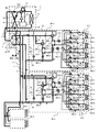
- FIG. 9 is a system circuit diagram (refrigerant circuit diagram) showing the flow of the refrigerant in the heating main operation mode of the air conditioner.
- a circuit indicated by a thick line in the refrigerant circuit in FIG. 9 is a refrigerant flow in the heating main operation mode.
- the flow direction of the heat source side refrigerant is indicated by solid arrows, and the flow direction of the heat medium is indicated by broken arrows.
- the load of the indoor unit 3 in the heating operation is the load of the indoor unit 3 in the cooling operation.
- the indoor unit 3 connected to the sub-relay unit 2b-1 is all heating operation
- the indoor unit 3 connected to the sub-relay unit 2b-2 is a mixture of heating operation and cooling operation. Let's drive.
- the low-temperature and low-pressure refrigerant flows into the compressor 10 and is discharged as a high-temperature and high-pressure gaseous refrigerant.
- the discharged high-temperature and high-pressure refrigerant passes through the first refrigerant flow switching device 11 and the check valve 13c in the outdoor unit 1, passes through the refrigerant pipe 4, and flows into the main relay unit 2a.
- the first refrigerant flow switching device 11 carries out the high-temperature and high-pressure gaseous refrigerant discharged from the compressor 10 to the outside of the outdoor unit 1 without passing through the heat source side heat exchanger 12 in the outdoor unit 1. It has been switched.
- the high-temperature and high-pressure gaseous refrigerant that has flowed into the main relay unit 2a passes through the gas side in the gas-liquid separator 21 and is carried out of the main relay unit 2a.
- the first throttling device 22 is closed, and the second throttling device 23 changes the opening so that the second pressure detecting device 45b has a constant pressure.
- the gaseous refrigerant carried out from the main relay unit 2a is branched and supplied to the sub-relay unit 2b in which the connection indoor unit 3 of the sub-relay unit 2b performs the heating operation, that is, 2b-1 and 2b-2.
- the gaseous refrigerant is supplied from the main relay unit 2a, and the second refrigerant flow switching device 28a-1 in the sub relay unit 2b-1, After passing through 28b-1, the heat exchange with the heat medium such as water or antifreeze liquid is performed inside by passing through the heat exchangers 25a-1 and 25b-1 between the heat medium. At this time, the second refrigerant flow switching devices 25a-1 and 25b-1 are switched to the heating side.
- the refrigerant that has been heat-exchanged with the heat medium in the second refrigerant flow switching device to become a high-temperature and high-pressure liquid refrigerant is expanded by passing through the third expansion devices 26a-1 and 26b-1, and has an intermediate pressure. It becomes a liquid refrigerant.
- the refrigerant that has been changed to the medium pressure liquid refrigerant in the third expansion devices 26a-1 and 26b-1 merges, a part of the refrigerant passes through the sub-unit second refrigerant flow path 52, and the sub-relay unit 2b. -1 and flows into the main relay unit 2a.
- the remaining refrigerant is carried out from the sub-relay unit 2b-1 to the sub-relay unit 2b in which the connected indoor unit is performing the cooling operation among the other sub-relay units, that is, the sub-relay unit 2b-2 in FIG. .
- the fourth diaphragm device 29-1 is fully closed.
- the fourth expansion device 29 may be an open / close device, and the open / close device is closed in the heating main operation mode.
- the gaseous refrigerant transported from the main relay unit 2a and the medium-pressure liquid refrigerant transported from the sub relay unit 2b-1 are introduced.
- the high-temperature and high-pressure gaseous refrigerant conveyed from the main relay unit 2a passes through the second refrigerant flow switching device 28b-2 and then passes to the heat exchanger related to heat medium 25b-2. Inflow.
- the second refrigerant flow switching device 28a-2 is switched to the cooling side, and the second refrigerant flow switching device 28b-2 is switched to the heating side.
- the high-temperature and high-pressure gaseous refrigerant flowing into the heat exchanger related to heat medium 25b-2 gives heat to the heat medium such as water and antifreeze that is also flowing into the heat exchanger related to heat medium 25b-2, and the high-temperature and high-pressure liquid It becomes.
- the refrigerant that has become a high-temperature and high-pressure liquid is expanded by passing through the third expansion device 26b-2 and becomes a medium-pressure liquid refrigerant.
- the third expansion device 26b-2 is controlled so that the degree of supercooling of the outlet refrigerant of the heat exchanger related to heat medium 25b-2 becomes a target value.
- the refrigerant that has become the medium-pressure liquid refrigerant merges with the medium-pressure liquid refrigerant conveyed from the sub-relay unit 2b-1, passes through the third expansion device 26a-2, and is a low-temperature and low-pressure two-phase refrigerant. And flows into the heat exchanger related to heat medium 25a-2. The refrigerant then receives heat from a heat medium such as water or antifreeze that is also flowing into the heat exchanger related to heat medium 25a-2.
- the third expansion device 26a-2 that passes at this time is controlled so that the degree of superheat of the refrigerant after heat exchange that has passed through the heat exchanger related to heat medium 25a-2 becomes a target value.
- the low-temperature and low-pressure two-phase refrigerant passes through the second refrigerant flow switching device 28a-2, and then merges with the low-temperature and low-pressure refrigerant discharged from the other sub-relay unit 2b, and then passes through the main relay unit 2a. Then, it is conveyed to the outdoor unit 1 through the refrigerant pipe 4 as it is. At this time, the fourth diaphragm device 29-2 is fully closed.
- the low-temperature and low-pressure two-phase refrigerant conveyed to the outdoor unit 1 passes through the check valve 13b and passes through the heat source side heat exchanger 12 by the first refrigerant flow switching device 11 to exchange heat with the outdoor space 6.
- the refrigerant becomes a low-temperature and low-pressure gaseous refrigerant, is led into the accumulator 19 by the first refrigerant flow switching device 11, and then returned to the compressor 10.
- the outdoor unit 1 is connected to the main relay unit 2a
- the main relay unit 2a is connected to at least one sub relay unit 2b
- each sub relay unit 2b is connected to the plurality of indoor units 3.
- each sub-relay unit 2b can exchange heat between the heat medium and the refrigerant in accordance with the total heat load of the indoor unit 3 connected thereto, and can perform the cooling operation and the heating operation simultaneously.
- the operation mode of the outdoor unit may be determined based on all the thermal loads of the sub relay unit connected to the main relay unit.
- a plurality of sub-relay units 2b can be connected, a plurality of indoor units 3 that can be operated individually can be connected.
- Heat source machine (outdoor unit) 2a Main relay unit 2b-1, 2b-2, 2b-3, 2b-4 Sub relay unit 3, 3a, 3b, 3c, 3d Indoor unit 4 Refrigerant piping 5 Heat medium piping 6 Outdoor space 7 Indoor space 8 Back of ceiling, etc.
Abstract
Description
冷媒を加圧し搬送する圧縮機と、前記冷媒の搬送流路を切替える第一の冷媒流路切替装置と、空気と前記冷媒とを熱交換する熱源側熱交換器とを有する室外ユニットと、
熱媒体が流通し前記熱媒体と空気との間で熱交換する利用側熱交換器を有する複数の室内ユニットと、
前記室外ユニットと前記室内ユニットの間に介在し、前記室外ユニットから搬送された前記冷媒と前記熱媒体との間で熱交換を行う中継ユニットとを備え、
前記中継ユニットは、
前記冷媒の圧力を調整する少なくとも一つ以上のメインユニット絞り装置を有し、前記室外ユニットと冷媒配管で接続されたメイン中継ユニットと、
前記冷媒と前記熱媒体との間で熱交換を行う複数の熱媒体間熱交換器と、前記メイン中継ユニットから搬送された前記冷媒の流路を切替える複数の第二の冷媒流路切替装置と、前記冷媒の圧力を調整する複数のサブユニット絞り装置と、前記熱媒体間熱交換器において前記冷媒と熱交換した前記熱媒体を、熱媒体配管を介して接続されている前記室内ユニットへ搬送する複数の熱媒体搬送装置と、前記室内ユニットの前記熱媒体搬出側及び搬入側に対応する位置に設置され、前記室内ユニットを流れる前記熱媒体の流路を前記複数の熱媒体熱交換器の間で切替える複数の熱媒体流路切替装置と、前記室内ユニットの前記熱媒体搬出側又は搬入側に対応する位置に設置され、前記熱媒体の流量を調整する複数の流量調整装置とを有し、前記メイン中継ユニットと冷媒配管で接続された1又は複数のサブ中継ユニットと、を備える。
また、サブ中継ユニットを複数台接続の場合において、各サブ中継ユニットがそれに接続されている室内ユニットの負荷に応じた熱媒体と冷媒の熱交換を行うよう、各サブ中継ユニットの総負荷に応じて、室外ユニットを冷房運転モード又は暖房運転モードで運転させることも可能である。これにより、各サブ中継ユニットに接続されている複数の室内機に関して冷暖房混在運転を行うことができる。
また、図1にあるように、室外ユニット1から搬送された冷媒はメイン中継ユニット2aによって気体、液体に分離された後サブ中継ユニット2bに搬送されることにより、複数台のサブ中継ユニット2bに対して負荷として必要な冷媒を同時に供給することができる。また、一方のサブ中継ユニット2b-1から得た排熱を他方のサブ中継ユニット2b-2へ供給することもできる。さらに、サブ中継ユニット2bから室内ユニット3へ温水と冷水を同時に供給することにより、複数の室内ユニット3の中で暖房運転と冷房運転を同時に行うことができる。
一方、熱媒体としては、例えば水、不凍液、水と不凍液の混合液、水と防食効果が高い添加剤の混合液等を用いることができる。
室外ユニット1は、冷媒を高温高圧に圧縮して冷媒経路内へ搬送するための圧縮機10と、室外ユニット1の運転モードを暖房運転モードと冷房運転モードに応じて冷媒の流れを切替える四方弁等の第一の冷媒流路切替装置11と、暖房運転時においては蒸発器、冷房運転時においては凝縮器として機能する熱源側熱交換器12とを基本要素にして構成されている。なお、暖房運転モードと冷房運転モードの違いによる余剰冷媒を蓄える又は過渡的な運転の変化に対する余剰冷媒を蓄えるアキュムレータ19を備えるのが好ましい。以上の各要素は冷媒配管4にて直列に接続されている。また、室外ユニット1には、冷媒接続配管4a、4b、及び一方向のみの冷媒の流れを許容するための逆止弁13a、13b、13c、13dが設けられている。これらの冷媒接続配管4a、4b、逆止弁13a、13b、13c、13dを室外ユニット1内に設置することにより、室内ユニット3の運転モードにかかわらず、メイン中継ユニット2a及びサブ中継ユニット2bに流入する冷媒の流れを一方向に固定することが可能となる。
室内ユニット3は、利用側熱交換器35(35a~35d)が搭載されており、この利用側熱交換器35は、水や不凍液等の熱媒体が流れる熱媒体配管5によってサブ中継ユニット2b内の熱媒体流量調整装置34(34a~34d)と熱媒体流路切替装置33(33a~33d)とに接続されている。利用側熱交換器35は、サブ中継ユニット2b-1から供給される熱媒体を流通させ、室内ユニット3においては図示省略しているファン等の送風機から供給される空気と熱媒体との間で熱交換を行ない、室内空間7に暖房用空気又は冷房用空気を供給する。
メイン中継ユニット2aは、室外ユニット1から搬送された冷媒を取り込み気体、液体に分離して送出する気液分離器21と、サブ中継ユニット2bから戻った冷媒を室外ユニット1へ戻すための冷媒戻り流路とを備えている。なおここでは、気液分離器21で分離されたガス冷媒が流れる流路をメインユニット第1冷媒流路41と、気液分離器21で分離された液冷媒がメインユニット絞り装置(第一の絞り装置22)を介して流れる流路をメインユニット第2冷媒流路42と、サブ中継ユニット2b-1からの戻り冷媒が流れる流路をメインユニット第3冷媒流路43と称する。
さらにここでは、別のメインユニット絞り装置(第二の絞り装置23)を介して、メインユニット第2冷媒流路42とメインユニット第3冷媒流路43とが、メインユニットバイパス流路44で接続されている。
また、メイン中継ユニット2aにおける第一の絞り装置22の前後には制御に使用する第一の圧力検知装置45aおよび第二の圧力検知装置45bが設置されている。
サブ中継ユニット2bは、2つ以上の熱媒体間熱交換器25(ここでは25a、25b)を有している。熱媒体間熱交換器25は熱源側の冷媒と利用側の熱媒体とで熱交換を行ない、室外ユニット1で生成され熱源側冷媒に貯えられた冷熱又は温熱を熱媒体に伝達するものである。したがって熱媒体間熱交換器25は、暖房運転の室内ユニット3に対して温熱媒体を供給する際には凝縮器(放熱器)として、冷房運転の室内ユニット3に対して冷熱媒体を供給する際には蒸発器として機能する。熱媒体間熱交換器25aは、第三の冷媒用絞り装置26aと第二の冷媒流路切替装置28aとの間に設けられており、全冷房運転時及び冷房暖房混在運転モード時においては熱媒体の冷却に用いられるものである。また、熱媒体間熱交換器25bは、第三の冷媒用絞り装置26bと第二の冷媒流路切替装置28bとの間に設けられており、全暖房運転時及び冷房暖房混在運転モード時において熱媒体の加熱に用いられるものである。
なお、第三の冷媒用絞り装置26a及び第三の冷媒用絞り装置26bは、例えば電子式膨張弁等の開度が可変に制御できるものが好ましい。
第二の冷媒流路切替装置28a、28bは、メインユニット第1冷媒流路41とメインユニット第3冷媒流路43の冷媒戻り流路とに切替可能に接続されている。
第三の冷媒用絞り装置26a、26bの熱媒体間熱交換器25a、25bとの反対側は、メインユニット第2冷媒流路42に接続されている。
またここでは、サブユニット第2冷媒流路52とサブユニット第3冷媒流路53との間を、第四の絞り装置29を介して、サブユニットバイパス流路54にて接続している。第四の絞り装置29として、流路の開口面積を制御する絞り装置を用いても、流路の開閉を行う開閉装置を用いてもよい。第四の絞り装置29を絞り装置とした場合は、運転状態により開度を制御することにより、サブユニット第2冷媒流路52とサブユニット第3冷媒流路53との間のサブユニットバイパス流路54を流れる冷媒量を調整することができ、開閉装置を用いる場合よりも、より細かい制御を行うことができる。
熱媒体流量調整装置34は室内ユニット3へ流入する熱媒体の温度及び流出する熱媒体の温度を検知することにより室内ユニット3へ流入する熱媒体の量を調整し、室内負荷に応じた最適な熱媒体量を提供可能とする。なお、熱媒体流量調整装置34は図2においては利用側熱交換器35と熱媒体流路切替装置32の間に設けているが、利用側熱交換器35と熱媒体流路切替装置33の間に設けても良い。また、室内ユニット3において、停止やサーモOFF等の空気調和装置からの負荷を必要としていないときは、熱媒体流量調整装置34を全閉にすることにより、室内ユニット3への熱媒体供給を止めることができる。
なお、図6~図9においては、メイン中継ユニット2aに対してサブ中継ユニット2bを四台接続したシステム図としているが、そのうち二台は簡易的に図示しており、以下に示すシステム動作は二台のシステム動作について述べたものである。しかし、四台以上の場合においてもサブ中継ユニット2bの動作は以下のシステム動作と同様である。また、メイン中継ユニット2aに対して、サブ中継ユニット2bは四台の設置に限定されるものではなく、またサブ中継ユニット2bに対して室内ユニットは四台のみ設置に限定されるものではない。なお、以下に示すシステムの動作において、熱媒体の動作については、図2~図5における各運転モードでの動作と同様であるため、以下ではそれらの説明を省略する。
図8においては、サブ中継ユニット2b-1、2b-2、2b-3、2b-4に接続されている室内ユニット3のうち冷房運転の室内ユニット3の負荷が暖房運転の室内ユニット3の負荷に比べて十分に大きいものとし、サブ中継ユニット2b-1へ接続されている室内ユニット3はすべて暖房運転、サブ中継ユニット2b-2へ接続されている室内ユニット3はすべて冷房運転とする。
図9において、サブ中継ユニット2b-1、2b-2、2b-3、2b-4に接続されている室内ユニット3のうち暖房運転の室内ユニット3の負荷が冷房運転の室内ユニット3の負荷に比べて十分に大きいものとし、サブ中継ユニット2b-1へ接続されている室内ユニット3はすべて暖房運転、サブ中継ユニット2b-2へ接続されている室内ユニット3は暖房運転と冷房運転との混在運転とする。
また、メイン中継ユニット2a一台に対して複数台のサブ中継ユニット2bを複数設置することにより、メイン中継ユニット2aにおいて気体と液体に分離した冷媒をそれぞれのサブ中継ユニット2bへ導くことが可能である。このため、各サブ中継ユニット2bがそれに接続されている室内ユニット3の全熱負荷に応じて、熱媒体と冷媒の熱交換を行い、冷房運転、暖房運転を同時に行うことができる。この場合、メイン中継ユニットに接続されているサブ中継ユニットの全ての熱負荷を基に、室外ユニットの運転モードを決定してもよい。
また、サブ中継ユニット2bが複数台接続可能であるため、個別に運転可能な複数の室内ユニット3を複数接続可能となる。
2a メイン中継ユニット
2b-1、2b-2、2b-3、2b-4 サブ中継ユニット
3、3a、3b、3c、3d 室内ユニット
4 冷媒配管
5 熱媒体配管
6 室外空間
7 室内空間
8 天井裏等の空間
9 ビル等の建物
10 圧縮機
11 第一の冷媒流路切替装置
12 熱源側熱交換器
13 逆止弁
19 アキュムレータ
21 気液分離器
22 第一の絞り装置(メインユニット絞り装置)
23 第二の絞り装置(メインユニット絞り装置)
25a、25b、 熱媒体間熱交換器
25a-1、25b-1、25a-2、25b-2 熱媒体間熱交換器
26a、26b 第三の絞り装置(サブユニット絞り装置)
26a-1、26b-1、26a-2、26b-2 第三の絞り装置(サブユニット絞り装置)
28a、28b 第二の冷媒流路切替装置
28a-1、28b-1、28a-2、28b-2 第二の冷媒流路切替装置
29、29-1、29-2 第四の絞り装置(サブユニット絞り装置)
31a、31b 熱媒体搬送装置
31a-1、31b-1、31a-2、31b-2 熱媒体搬送装置
32a、32b、32c、32d 熱媒体流路切替装置(出口側)
32a-1、32b-1、32c-1、32d-1 熱媒体流路切替装置(出口側)
32a-2、32b-2、32c-2、32d-2 熱媒体流路切替装置(出口側)
33a、33b、33c、33d 熱媒体流路切替装置(入口側)
33a-1、33b-1、33c-1、33d-1 熱媒体流路切替装置(入口側)
33a-2、33b-2、33c-2、33d-2 熱媒体流路切替装置(入口側)
34a、34b、34c、34d 熱媒体流量調整装置
34a-1、34b-1、34c-1、34d-1 熱媒体流量調整装置
34a-2、34b-2、34c-2、34d-2 熱媒体流量調整装置
35a、35b、35c、35d 利用側熱交換器
35a-1、35b-1、35c-1、35d-1 利用側熱交換器
35a-2、35b-2、35c-2、35d-2 利用側熱交換器
41 メインユニット第1冷媒流路
42 メインユニット第2冷媒流路
43 メインユニット第3冷媒流路
44 メインユニットバイパス流路
45a 第一の圧力検知装置
45b 第二の圧力検知装置
51 サブユニット第1冷媒流路
52 サブユニット第2冷媒流路
53 サブユニット第3冷媒流路
54 サブユニットバイパス流路
Claims (11)
- 冷媒を加圧し搬送する圧縮機と、前記冷媒の搬送流路を切替える第一の冷媒流路切替装置と、空気と前記冷媒とを熱交換する熱源側熱交換器とを有する室外ユニットと、
熱媒体が流通し前記熱媒体と空気との間で熱交換する利用側熱交換器を有する複数の室内ユニットと、
前記室外ユニットと前記室内ユニットの間に介在し、前記室外ユニットから搬送された前記冷媒と前記熱媒体との間で熱交換を行う中継ユニットとを備え、
前記中継ユニットは、
前記冷媒の圧力を調整する少なくとも一つ以上のメインユニット絞り装置を有し、前記室外ユニットと冷媒配管で接続されたメイン中継ユニットと、
前記冷媒と前記熱媒体との間で熱交換を行う複数の熱媒体間熱交換器と、前記メイン中継ユニットから搬送された前記冷媒の流路を切替える複数の第二の冷媒流路切替装置と、前記冷媒の圧力を調整する複数のサブユニット絞り装置と、前記熱媒体間熱交換器において前記冷媒と熱交換した前記熱媒体を、熱媒体配管を介して接続されている前記室内ユニットへ搬送する複数の熱媒体搬送装置と、前記室内ユニットの前記熱媒体搬出側及び搬入側に対応する位置に設置され、前記室内ユニットを流れる前記熱媒体の流路を前記複数の熱媒体熱交換器の間で切替える複数の熱媒体流路切替装置と、前記室内ユニットの前記熱媒体搬出側又は搬入側に対応する位置に設置され、前記熱媒体の流量を調整する複数の流量調整装置とを有し、前記メイン中継ユニットと冷媒配管で接続された1又は複数のサブ中継ユニットと、を備えたことを特徴とする空気調和装置。 - メイン中継ユニットに、前記室外ユニットから搬送された前記冷媒を気体と液体に分けて搬送する気液分離器を備えたことを特徴とする請求項1に記載の空気調和装置。
- 前記室外ユニットと前記メイン中継ユニットは2本の配管で接続され、前記メイン中継ユニットと前記サブ中継ユニットは3本の配管で接続されていることを特徴とする請求項1又は2に記載の空気調和装置。
- 前記メイン中継ユニットは、
前記気液分離器で分離されたガス冷媒が流れるメインユニット第1冷媒流路と、
前記気液分離器で分離された液冷媒が前記メインユニット絞り装置の1つを介して流れるメインユニット第2冷媒流路と、
前記サブ中継ユニットからの戻り冷媒が流れるメインユニット第3冷媒流路と、を備えていることを特徴とする請求項2又は3に記載の空気調和装置。 - 前記サブ中継ユニットは、
前記メインユニット第1冷媒流路と連通しているサブユニット第1冷媒流路と、
前記メインユニット第2冷媒流路と連通しているサブユニット第2冷媒流路と、
前記メイン中継ユニットに戻る冷媒が流れるサブユニット第3冷媒流路と、を備え、
前記サブユニット第1冷媒流路と前記サブユニット第2冷媒流路とが、前記第二の冷媒流路切替装置、前記熱媒体間熱交換器及び前記サブユニット絞り装置が直列接続されてなる複数の流路を介して接続されており、
前記第二の冷媒流路切替装置は、前記熱媒体間熱交換器を前記サブユニット第1冷媒流路と前記サブユニット第3冷媒流路との間で切替接続するものであることを特徴とする請求項4に記載の空気調和装置。 - 前記メインユニット絞り装置のうちの別の1つを介して、前記メインユニット第2冷媒流路と前記メインユニット第3冷媒流路とが接続されていることを特徴とする請求項4に記載の空気調和装置。
- 前記サブユニット絞り装置のうちの別の1つまたはサブユニット開閉装置を介して、前記サブユニット第2冷媒流路と前記サブユニット第3冷媒流路とが接続されていることを特徴とする請求項5に記載の空気調和装置。
- 運転中の前記複数の室内ユニットの全てが暖房運転を行う全暖房運転モード、運転中の前記複数の室内ユニットの全てが冷房運転を行う全冷房運転モード、前記複数の室内ユニットのなかで暖房運転を行うものと冷房運転を行うものが混在する冷暖房混在運転モードとを備えたことを特徴とする請求項1~7のいずれか一項に記載の空気調和装置。
- 前記冷暖房混在運転モードは、1つの前記サブ中継ユニットに接続された複数の前記室内ユニットのなかで暖房運転と冷房運転が混在するものであることを特徴とする請求項8に記載の空気調和装置。
- 前記冷暖房混在運転モードは、前記複数のサブ中継ユニットに接続されている複数の前記室内ユニットが、前記サブ中継ユニット毎に暖房運転と冷房運転とを行うものであることを特徴とする請求項8に記載の空気調和装置。
- 前記メイン中継ユニットに接続されている前記サブ中継ユニットの全ての熱負荷を基に、前記室外ユニットの運転モードが決定されることを特徴とする請求項8に記載の空気調和装置。
Priority Applications (6)
| Application Number | Priority Date | Filing Date | Title |
|---|---|---|---|
| ES09850834T ES2748323T3 (es) | 2009-10-29 | 2009-10-29 | Dispositivo de aire acondicionado |
| CN200980162150.XA CN102597656B (zh) | 2009-10-29 | 2009-10-29 | 空调装置 |
| EP09850834.4A EP2495514B1 (en) | 2009-10-29 | 2009-10-29 | Air conditioning device |
| PCT/JP2009/068554 WO2011052055A1 (ja) | 2009-10-29 | 2009-10-29 | 空気調和装置 |
| US13/501,325 US9310086B2 (en) | 2009-10-29 | 2009-10-29 | Air-conditioning apparatus |
| JP2011538155A JP5323202B2 (ja) | 2009-10-29 | 2009-10-29 | 空気調和装置 |
Applications Claiming Priority (1)
| Application Number | Priority Date | Filing Date | Title |
|---|---|---|---|
| PCT/JP2009/068554 WO2011052055A1 (ja) | 2009-10-29 | 2009-10-29 | 空気調和装置 |
Publications (1)
| Publication Number | Publication Date |
|---|---|
| WO2011052055A1 true WO2011052055A1 (ja) | 2011-05-05 |
Family
ID=43921496
Family Applications (1)
| Application Number | Title | Priority Date | Filing Date |
|---|---|---|---|
| PCT/JP2009/068554 WO2011052055A1 (ja) | 2009-10-29 | 2009-10-29 | 空気調和装置 |
Country Status (6)
| Country | Link |
|---|---|
| US (1) | US9310086B2 (ja) |
| EP (1) | EP2495514B1 (ja) |
| JP (1) | JP5323202B2 (ja) |
| CN (1) | CN102597656B (ja) |
| ES (1) | ES2748323T3 (ja) |
| WO (1) | WO2011052055A1 (ja) |
Cited By (6)
| Publication number | Priority date | Publication date | Assignee | Title |
|---|---|---|---|---|
| WO2012160597A1 (ja) * | 2011-05-23 | 2012-11-29 | 三菱電機株式会社 | 空気調和装置 |
| JP2014081094A (ja) * | 2012-10-13 | 2014-05-08 | Corona Corp | ヒートポンプシステム |
| WO2015059814A1 (ja) | 2013-10-25 | 2015-04-30 | 三菱電機株式会社 | 冷凍サイクル装置 |
| EP2808622A4 (en) * | 2012-01-24 | 2016-04-06 | Mitsubishi Electric Corp | AIR CONDITIONING |
| JP6012757B2 (ja) * | 2012-11-21 | 2016-10-25 | 三菱電機株式会社 | 空気調和装置 |
| WO2020059106A1 (ja) * | 2018-09-21 | 2020-03-26 | 三菱電機株式会社 | 中継機 |
Families Citing this family (10)
| Publication number | Priority date | Publication date | Assignee | Title |
|---|---|---|---|---|
| WO2014057550A1 (ja) * | 2012-10-10 | 2014-04-17 | 三菱電機株式会社 | 空気調和装置 |
| WO2014083680A1 (ja) * | 2012-11-30 | 2014-06-05 | 三菱電機株式会社 | 空気調和装置 |
| JP6003635B2 (ja) * | 2012-12-28 | 2016-10-05 | ダイキン工業株式会社 | 空気調和装置及び空気調和装置の施工方法 |
| CN109386887B (zh) * | 2014-02-21 | 2021-01-01 | 大金工业株式会社 | 空调装置 |
| KR101702737B1 (ko) * | 2015-01-15 | 2017-02-03 | 엘지전자 주식회사 | 공기 조화 시스템 |
| WO2017216861A1 (ja) * | 2016-06-14 | 2017-12-21 | 三菱電機株式会社 | 空気調和装置 |
| KR102470528B1 (ko) * | 2018-05-18 | 2022-11-25 | 엘지전자 주식회사 | 공기조화 시스템 및 공기조화 시스템의 배관 탐색 방법 |
| KR20210083047A (ko) | 2019-12-26 | 2021-07-06 | 엘지전자 주식회사 | 공기조화장치 |
| KR20210085443A (ko) | 2019-12-30 | 2021-07-08 | 엘지전자 주식회사 | 공기조화장치 |
| KR20210098783A (ko) * | 2020-02-03 | 2021-08-11 | 엘지전자 주식회사 | 공기조화장치 |
Citations (9)
| Publication number | Priority date | Publication date | Assignee | Title |
|---|---|---|---|---|
| JPS6176852A (ja) * | 1984-08-20 | 1986-04-19 | 株式会社富士通ゼネラル | 分離形空気調和機 |
| JPH04359767A (ja) * | 1991-06-04 | 1992-12-14 | Mitsubishi Electric Corp | 空気調和装置 |
| JPH05280818A (ja) | 1992-04-01 | 1993-10-29 | Matsushita Refrig Co Ltd | 多室冷暖房装置 |
| JP2001289465A (ja) | 2000-04-11 | 2001-10-19 | Daikin Ind Ltd | 空気調和装置 |
| JP2002106995A (ja) * | 2000-09-29 | 2002-04-10 | Hitachi Ltd | 空気調和機 |
| JP2003343936A (ja) | 2002-05-28 | 2003-12-03 | Mitsubishi Electric Corp | 冷凍サイクル装置 |
| JP2004053069A (ja) * | 2002-07-17 | 2004-02-19 | Fuji Electric Retail Systems Co Ltd | 冷媒回路、およびそれを用いた自動販売機 |
| JP2004226015A (ja) * | 2003-01-24 | 2004-08-12 | Sanyo Electric Co Ltd | 冷温水供給システム |
| JP2005140444A (ja) | 2003-11-07 | 2005-06-02 | Matsushita Electric Ind Co Ltd | 空気調和機およびその制御方法 |
Family Cites Families (15)
| Publication number | Priority date | Publication date | Assignee | Title |
|---|---|---|---|---|
| JP2705031B2 (ja) * | 1989-06-13 | 1998-01-26 | 松下冷機株式会社 | 多室式空気調和機 |
| US5237833A (en) * | 1991-01-10 | 1993-08-24 | Mitsubishi Denki Kabushiki Kaisha | Air-conditioning system |
| JP2922002B2 (ja) * | 1991-02-20 | 1999-07-19 | 株式会社東芝 | 空気調和機 |
| AU649810B2 (en) * | 1991-05-09 | 1994-06-02 | Mitsubishi Denki Kabushiki Kaisha | Air conditioning apparatus |
| JP2616525B2 (ja) * | 1991-12-09 | 1997-06-04 | 三菱電機株式会社 | 空気調和装置 |
| MY114473A (en) * | 1997-04-08 | 2002-10-31 | Daikin Ind Ltd | Refrigerating system |
| CN1142392C (zh) * | 2000-03-27 | 2004-03-17 | 张委三 | 分体式冷热水机组 |
| KR100437805B1 (ko) * | 2002-06-12 | 2004-06-30 | 엘지전자 주식회사 | 냉난방 동시형 멀티공기조화기 및 그 제어방법 |
| JP2004086726A (ja) * | 2002-08-28 | 2004-03-18 | Sanden Corp | 食品冷却加温装置 |
| JP4269306B2 (ja) * | 2002-09-20 | 2009-05-27 | 三菱電機株式会社 | 多室用空気調和機 |
| CN1695034B (zh) * | 2002-10-30 | 2010-11-17 | 三菱电机株式会社 | 空调装置 |
| KR100504498B1 (ko) * | 2003-01-13 | 2005-08-03 | 엘지전자 주식회사 | 공기조화기용 과냉확보장치 |
| EP1816416B1 (en) * | 2004-11-25 | 2019-06-19 | Mitsubishi Denki Kabushiki Kaisha | Air conditioner |
| CN100470170C (zh) * | 2007-01-11 | 2009-03-18 | 清华大学 | 太阳能辅助空气源跨临界二氧化碳热泵综合空调系统 |
| CN201273744Y (zh) * | 2008-08-15 | 2009-07-15 | 李恩重 | 一种取暖制冷两用装置 |
-
2009
- 2009-10-29 WO PCT/JP2009/068554 patent/WO2011052055A1/ja active Application Filing
- 2009-10-29 ES ES09850834T patent/ES2748323T3/es active Active
- 2009-10-29 US US13/501,325 patent/US9310086B2/en active Active
- 2009-10-29 EP EP09850834.4A patent/EP2495514B1/en active Active
- 2009-10-29 JP JP2011538155A patent/JP5323202B2/ja active Active
- 2009-10-29 CN CN200980162150.XA patent/CN102597656B/zh active Active
Patent Citations (9)
| Publication number | Priority date | Publication date | Assignee | Title |
|---|---|---|---|---|
| JPS6176852A (ja) * | 1984-08-20 | 1986-04-19 | 株式会社富士通ゼネラル | 分離形空気調和機 |
| JPH04359767A (ja) * | 1991-06-04 | 1992-12-14 | Mitsubishi Electric Corp | 空気調和装置 |
| JPH05280818A (ja) | 1992-04-01 | 1993-10-29 | Matsushita Refrig Co Ltd | 多室冷暖房装置 |
| JP2001289465A (ja) | 2000-04-11 | 2001-10-19 | Daikin Ind Ltd | 空気調和装置 |
| JP2002106995A (ja) * | 2000-09-29 | 2002-04-10 | Hitachi Ltd | 空気調和機 |
| JP2003343936A (ja) | 2002-05-28 | 2003-12-03 | Mitsubishi Electric Corp | 冷凍サイクル装置 |
| JP2004053069A (ja) * | 2002-07-17 | 2004-02-19 | Fuji Electric Retail Systems Co Ltd | 冷媒回路、およびそれを用いた自動販売機 |
| JP2004226015A (ja) * | 2003-01-24 | 2004-08-12 | Sanyo Electric Co Ltd | 冷温水供給システム |
| JP2005140444A (ja) | 2003-11-07 | 2005-06-02 | Matsushita Electric Ind Co Ltd | 空気調和機およびその制御方法 |
Cited By (13)
| Publication number | Priority date | Publication date | Assignee | Title |
|---|---|---|---|---|
| US9494348B2 (en) | 2011-05-23 | 2016-11-15 | Mitsubishi Electric Corporation | Air-conditioning apparatus |
| JPWO2012160597A1 (ja) * | 2011-05-23 | 2014-07-31 | 三菱電機株式会社 | 空気調和装置 |
| WO2012160597A1 (ja) * | 2011-05-23 | 2012-11-29 | 三菱電機株式会社 | 空気調和装置 |
| EP2808622A4 (en) * | 2012-01-24 | 2016-04-06 | Mitsubishi Electric Corp | AIR CONDITIONING |
| JP2014081094A (ja) * | 2012-10-13 | 2014-05-08 | Corona Corp | ヒートポンプシステム |
| JPWO2014080464A1 (ja) * | 2012-11-21 | 2017-01-05 | 三菱電機株式会社 | 空気調和装置 |
| JP6012757B2 (ja) * | 2012-11-21 | 2016-10-25 | 三菱電機株式会社 | 空気調和装置 |
| WO2015059814A1 (ja) | 2013-10-25 | 2015-04-30 | 三菱電機株式会社 | 冷凍サイクル装置 |
| JP6000469B2 (ja) * | 2013-10-25 | 2016-09-28 | 三菱電機株式会社 | 冷凍サイクル装置 |
| JPWO2015059814A1 (ja) * | 2013-10-25 | 2017-03-09 | 三菱電機株式会社 | 冷凍サイクル装置 |
| US10139142B2 (en) | 2013-10-25 | 2018-11-27 | Mitsubishi Electric Corporation | Refrigeration cycle apparatus including a plurality of branch units |
| WO2020059106A1 (ja) * | 2018-09-21 | 2020-03-26 | 三菱電機株式会社 | 中継機 |
| JPWO2020059106A1 (ja) * | 2018-09-21 | 2021-03-11 | 三菱電機株式会社 | 中継機 |
Also Published As
| Publication number | Publication date |
|---|---|
| ES2748323T3 (es) | 2020-03-16 |
| CN102597656A (zh) | 2012-07-18 |
| EP2495514B1 (en) | 2019-08-28 |
| JPWO2011052055A1 (ja) | 2013-03-14 |
| US20120198879A1 (en) | 2012-08-09 |
| EP2495514A4 (en) | 2018-04-04 |
| EP2495514A1 (en) | 2012-09-05 |
| US9310086B2 (en) | 2016-04-12 |
| JP5323202B2 (ja) | 2013-10-23 |
| CN102597656B (zh) | 2014-10-15 |
Similar Documents
| Publication | Publication Date | Title |
|---|---|---|
| JP5323202B2 (ja) | 空気調和装置 | |
| JP5188571B2 (ja) | 空気調和装置 | |
| JP5752148B2 (ja) | 空気調和装置 | |
| JP5784117B2 (ja) | 空気調和装置 | |
| JP6095764B2 (ja) | 空気調和装置 | |
| WO2014097869A1 (ja) | 空気調和装置 | |
| JP5595521B2 (ja) | ヒートポンプ装置 | |
| US9557083B2 (en) | Air-conditioning apparatus with multiple operational modes | |
| JP5490245B2 (ja) | 空気調和装置 | |
| WO2013008365A1 (ja) | 空気調和装置 | |
| WO2013069351A1 (ja) | 空気調和装置 | |
| AU2011358039A1 (en) | Air-conditioning apparatus | |
| WO2011099067A1 (ja) | 冷凍サイクル装置 | |
| CN108139106B (zh) | 空气调节装置 | |
| JP5312681B2 (ja) | 空気調和装置 | |
| WO2011052050A1 (ja) | 空気調和装置 | |
| JP2014089042A (ja) | 冷凍サイクル装置 | |
| WO2016113830A1 (ja) | 空気調和装置 | |
| WO2014128971A1 (ja) | 空気調和装置 | |
| WO2023007700A1 (ja) | 空気調和装置 | |
| WO2015079531A1 (ja) | 空気調和装置 | |
| WO2012160605A1 (ja) | 空気調和装置 |
Legal Events
| Date | Code | Title | Description |
|---|---|---|---|
| WWE | Wipo information: entry into national phase |
Ref document number: 200980162150.X Country of ref document: CN |
|
| 121 | Ep: the epo has been informed by wipo that ep was designated in this application |
Ref document number: 09850834 Country of ref document: EP Kind code of ref document: A1 |
|
| WWE | Wipo information: entry into national phase |
Ref document number: 2011538155 Country of ref document: JP |
|
| WWE | Wipo information: entry into national phase |
Ref document number: 13501325 Country of ref document: US |
|
| WWE | Wipo information: entry into national phase |
Ref document number: 2009850834 Country of ref document: EP |
|
| NENP | Non-entry into the national phase |
Ref country code: DE |