WO2011049013A1 - 非平行軸伝動機構及びロボット - Google Patents
非平行軸伝動機構及びロボット Download PDFInfo
- Publication number
- WO2011049013A1 WO2011049013A1 PCT/JP2010/068138 JP2010068138W WO2011049013A1 WO 2011049013 A1 WO2011049013 A1 WO 2011049013A1 JP 2010068138 W JP2010068138 W JP 2010068138W WO 2011049013 A1 WO2011049013 A1 WO 2011049013A1
- Authority
- WO
- WIPO (PCT)
- Prior art keywords
- conical
- pulley
- belt
- pulleys
- fan
- Prior art date
Links
Images


Classifications
-
- B—PERFORMING OPERATIONS; TRANSPORTING
- B25—HAND TOOLS; PORTABLE POWER-DRIVEN TOOLS; MANIPULATORS
- B25J—MANIPULATORS; CHAMBERS PROVIDED WITH MANIPULATION DEVICES
- B25J19/00—Accessories fitted to manipulators, e.g. for monitoring, for viewing; Safety devices combined with or specially adapted for use in connection with manipulators
- B25J19/06—Safety devices
-
- B—PERFORMING OPERATIONS; TRANSPORTING
- B25—HAND TOOLS; PORTABLE POWER-DRIVEN TOOLS; MANIPULATORS
- B25J—MANIPULATORS; CHAMBERS PROVIDED WITH MANIPULATION DEVICES
- B25J9/00—Programme-controlled manipulators
- B25J9/10—Programme-controlled manipulators characterised by positioning means for manipulator elements
- B25J9/102—Gears specially adapted therefor, e.g. reduction gears
-
- F—MECHANICAL ENGINEERING; LIGHTING; HEATING; WEAPONS; BLASTING
- F16—ENGINEERING ELEMENTS AND UNITS; GENERAL MEASURES FOR PRODUCING AND MAINTAINING EFFECTIVE FUNCTIONING OF MACHINES OR INSTALLATIONS; THERMAL INSULATION IN GENERAL
- F16H—GEARING
- F16H19/00—Gearings comprising essentially only toothed gears or friction members and not capable of conveying indefinitely-continuing rotary motion
- F16H19/001—Gearings comprising essentially only toothed gears or friction members and not capable of conveying indefinitely-continuing rotary motion for conveying reciprocating or limited rotary motion
- F16H19/003—Gearings comprising essentially only toothed gears or friction members and not capable of conveying indefinitely-continuing rotary motion for conveying reciprocating or limited rotary motion comprising a flexible member
- F16H19/005—Gearings comprising essentially only toothed gears or friction members and not capable of conveying indefinitely-continuing rotary motion for conveying reciprocating or limited rotary motion comprising a flexible member for conveying oscillating or limited rotary motion
-
- Y—GENERAL TAGGING OF NEW TECHNOLOGICAL DEVELOPMENTS; GENERAL TAGGING OF CROSS-SECTIONAL TECHNOLOGIES SPANNING OVER SEVERAL SECTIONS OF THE IPC; TECHNICAL SUBJECTS COVERED BY FORMER USPC CROSS-REFERENCE ART COLLECTIONS [XRACs] AND DIGESTS
- Y10—TECHNICAL SUBJECTS COVERED BY FORMER USPC
- Y10T—TECHNICAL SUBJECTS COVERED BY FORMER US CLASSIFICATION
- Y10T74/00—Machine element or mechanism
- Y10T74/18—Mechanical movements
- Y10T74/18856—Oscillating to oscillating
-
- Y—GENERAL TAGGING OF NEW TECHNOLOGICAL DEVELOPMENTS; GENERAL TAGGING OF CROSS-SECTIONAL TECHNOLOGIES SPANNING OVER SEVERAL SECTIONS OF THE IPC; TECHNICAL SUBJECTS COVERED BY FORMER USPC CROSS-REFERENCE ART COLLECTIONS [XRACs] AND DIGESTS
- Y10—TECHNICAL SUBJECTS COVERED BY FORMER USPC
- Y10T—TECHNICAL SUBJECTS COVERED BY FORMER US CLASSIFICATION
- Y10T74/00—Machine element or mechanism
- Y10T74/20—Control lever and linkage systems
- Y10T74/20207—Multiple controlling elements for single controlled element
- Y10T74/20305—Robotic arm
- Y10T74/20329—Joint between elements
Definitions
- the present invention relates to a non-parallel axis belt transmission mechanism that transmits power to a non-parallel axis such as an orthogonal axis using a belt and a robot using the same.
- Non-parallel shaft transmission mechanisms that transmit power to non-parallel axes are used in many machines including robot joints.
- the orthogonal shaft transmission mechanism is particularly often used, and there is an example of a differential mechanism.
- the most common non-parallel shaft transmission mechanism is a bevel gear, but the bevel gear requires a certain amount of clearance to suppress friction, so it has a high backlash and high rigidity so that tooth missing does not occur. It is necessary to use materials, and a heavy technical problem is that the weight is increased.
- a non-parallel shaft transmission mechanism using a wire has been devised (see, for example, Patent Document 1).
- the conventional non-parallel shaft transmission mechanism using a wire like a mechanism using a general wire, increases the load on the wire, which prevents the application to industrial equipment due to the problem of wire reliability. It was. Further, in the conventional mechanism, it is necessary to fix the ends of the wires to the pulleys, and the wires overlap each other after one rotation, so that there is a problem that the movable range is limited to one rotation.
- the present invention has been made in view of such problems, and is a non-parallel shaft belt transmission mechanism that has high durability, can transmit power to orthogonal axes without limitation of the movable range, and can also be used as a differential mechanism.
- the purpose is to provide.
- the non-parallel shaft transmission mechanism has a plurality of pulleys, a support shaft that rotatably supports each of the pulleys, and a power that is input to any of the plurality of pulleys with a rotation shaft in parallel.
- a transmission medium that is not transmitted to the other pulley, and the transmission medium is a fan belt having a fan-shaped shape developed in a plane, and the pulley is on a contact surface with the fan belt.
- a conical pulley is formed by setting a virtual conical surface and subtracting the surface shape of the fan belt from the virtual conical surface, and the rotational axis of the conical pulley is the center line of the cone formed by the virtual conical surface. And at least two of the plurality of conical pulleys are arranged such that the positions of the vertices of the respective virtual conical surfaces coincide with each other. According to a second aspect of the present invention, in the non-parallel shaft transmission mechanism, at least two of the plurality of conical pulleys are arranged so that the virtual conical surfaces are in contact with each other, and the two fan belts are adjacent to each other.
- the fan belt is a V-belt having at least one protrusion having a V-shaped or trapezoidal cross section, and the conical pulley has a groove corresponding thereto. It is. Further, in the non-parallel shaft transmission mechanism according to claim 4, the shape of the V-shaped or trapezoidal protrusion of the fan belt is such that the angle formed by the fan-shaped central surface and the belt surface is the fan-shaped outer surface and the belt surface.
- the fan belt is a timing belt provided with a plurality of tooth-like projections in the traveling direction of the belt
- the conical pulley is a timing pulley provided with a corresponding groove. It is what is.
- the tooth shape of the timing belt of the fan belt is a wedge-shaped protrusion that becomes wider toward the outside of the fan shape, and the conical pulley has a groove corresponding thereto. is there.
- any two of the plurality of conical pulleys are respectively formed as a conical pulley 1 and a conical pulley 2, and one end of the fan belt is the conical pulley 1.
- the other end fixing fan belt is fixed to the conical pulley 2 at the other end.
- the two adjacent conical pulleys are a conical pulley A and a conical pulley B, respectively, and the virtual conical surface of the conical pulley A and the conical pulley B A tangent to the virtual conical surface is defined as a virtual conical tangent, and the two both-end fixed fan belts are provided.
- One of the both-end fixed fan belts is wound around the conical pulley A in a clockwise direction when viewed from the vertex direction of the virtual conical surface. It is wound around the conical pulley B counterclockwise as viewed from the apex direction of the virtual conical surface with the virtual conical tangent as a boundary, and the other both-end fixing belt is anti-clockwise when viewed from the apex direction of the virtual conical surface. It is wound around the conical pulley A in the clockwise direction and wound around the conical pulley B in the clockwise direction as viewed from the apex direction of the virtual conical surface with the virtual cone tangent as a boundary.
- the non-parallel shaft transmission mechanism according to claim 9 is a fan-shaped belt in which the fan belt is formed by connecting both ends of the fan-shape.
- the non-parallel shaft transmission mechanism according to claim 10 includes an integer n main conical pulleys of 2 or more of the plurality of conical pulleys, and 2 (n-1) guide conical pulleys, The main conical pulley and the guide conical pulley are arranged so that the positions of the vertices of the virtual conical surfaces coincide with each other, and two guide conical pulleys are provided between the main conical pulleys connected in a daisy chain.
- the non-parallel shaft transmission mechanism includes an integer n main conical pulleys of 2 or more of the plurality of conical pulleys, and 2n guide conical pulleys,
- the guide conical pulleys are arranged so that the positions of the vertices of the respective virtual conical surfaces coincide with each other, and the guide conical pulleys are arranged between the main conical pulleys that are connected in an annular shape, and each two of the guide conical pulleys are arranged in two.
- the non-parallel shaft transmission mechanism includes two input conical pulleys among the plurality of conical pulleys, one or more integer n main conical pulleys, and 4n guide conical pulleys.
- the input conical pulley, the main conical pulley, and the guide conical pulley are arranged such that the positions of the vertices of the virtual conical surfaces coincide with each other, and the rotation axes of the two input conical pulleys are Are arranged on the same straight line, the rotation axis of the main conical pulley is arranged to be perpendicular to the rotation axis of the input conical pulley, the guide conical pulley is in contact with each of the four main conical pulleys, and 4 Two of them are in contact with one of the input conical pulleys and the other two are in contact with the other of the input conical pulleys.
- the non-parallel shaft transmission mechanism according to claim 13, wherein the main conical pulley is a timing pulley, and the guide cone is arranged such that a development center angle of the fan belt is an integral multiple of a tooth groove pitch of the main conical pulley.
- the radius of the frustum bottom surface of the virtual conical surface of the pulley is set.
- the non-parallel shaft transmission mechanism according to claim 14 includes a support frame for supporting the guide conical pulley and a support frame for fixing the support shaft for supporting the output pulley, and the two support frames are provided.
- the input conical pulley is rotatably supported around the rotation axis.
- the non-parallel shaft transmission mechanism includes at least one support member that slide-contacts and supports the fan belt, and the support member sets a virtual conical surface as a contact surface with the fan belt.
- the fan belts are arranged so that the virtual conical surfaces are in contact with each other, and the fan belt is a surface opposite to the tangent line of the virtual conical surfaces, and the conical pulley and the It is assumed that it is in contact with the conical support member.
- the robot according to a sixteenth aspect includes a plurality of arm members and a joint portion that connects the arm members so as to be capable of turning or rotating, and the joint portion includes the joint members according to the first to fifteenth aspects. It has a non-parallel shaft transmission mechanism.
- power can be transmitted to the shaft which is not parallel, without twisting a belt. Since a belt is used, a lighter material can be used than when a bevel gear is used, so the mechanism is lightweight and transmission can be performed with less backlash. Moreover, since a belt is used, durability can be increased as compared with the case where a wire is used. Moreover, according to the invention of Claim 2, it can arrange
- the belt can be made difficult to come off, and the protrusion of the belt can be made difficult to deform. Therefore, the protrusion can be reduced, the belt can be easily bent, and the durability of the belt can be enhanced.
- even a strong force can be transmitted without slipping.
- power can be transmitted without the belt sliding in the direction of the tip of the cone.
- power can be transmitted to a pulley whose rotational axis is not parallel by a simple mechanism without using a guide pulley or the like.
- power can be transmitted by a simple mechanism to adjacent pulleys whose rotation axes are not parallel without using a guide pulley or the like.
- the rotational power in both directions can be continuously transmitted to the pulley whose rotational axis is not parallel.
- the rotational power in both directions can be continuously transmitted to a plurality of pulleys adjacent to the daisy chain where the rotation axes are not parallel.
- the rotational power in both directions can be continuously transmitted to a plurality of pulleys adjacent to each other in an annular shape whose rotation axis is not parallel.
- the rotational power in both directions is continuously transmitted to two pulleys having rotating shafts on the same straight line and a plurality of adjacent pulleys having a rotating shaft perpendicular to the pulleys. can do.
- the invention of claim 13 even when the fan-shaped belt is a timing belt, there is no belt deflection and the like, teeth and grooves can be properly meshed, and a plurality of adjacent pulleys that are not parallel to the rotation axis.
- the power of rotation in both directions can be transmitted continuously.
- the pulley When a wire is used, the pulley requires four steps to make a differential mechanism. However, since the pulley can be made one step, it can be reduced in size and weight, and there is no backlash using a belt and durability is improved. A high orthogonal axis differential mechanism can be realized.
- sheet metal, plastic or the like can be used. According to the invention described in claim 16, power can be transmitted without the belt sliding in the direction of the tip of the cone or in the transmission direction. In addition, according to the invention described in claim 17, a fan belt having high rigidity can be easily manufactured. According to the invention of claim 18, power can be transmitted without the belt slipping in the direction of the tip of the cone or in the transmission direction.
- the pulleys can be transmitted without interfering with each other.
- power can be transmitted without the belt sliding in the direction of the tip of the cone or in the transmission direction.
- the timing fan belt can be easily manufactured.
- the three-view figure and perspective view which show the principal part of the orthogonal axis
- the perspective view which shows the whole image of the orthogonal axis
- the exploded view which shows the internal structure of the orthogonal axis
- the front view, right view, and perspective view which show the principal part of the orthogonal axis
- deployment center angle of 6th Embodiment of this invention The expanded view which shows a part of fan belt of 8th Embodiment of this invention.
- FIG. 1 is a three-sided view showing one of the simplest structural examples of the non-parallel shaft belt transmission mechanism of the present invention
- FIG. 1 (a) is a front view
- FIG. 1 (b) is a right side view
- FIG. (C) is a bottom view.
- 1 and 2 are conical pulleys
- 3 and 4 are fan belts.
- the conical pulley is a pulley having a shape obtained by subtracting the belt thickness with reference to a conical surface virtually set at a contact portion with the fan belt. This virtually set conical surface is described as a “virtual conical surface”.
- the conical pulley 1 is fixed so as to be rotatable around the rotation axis 5 and the conical pulley 2 is fixed around the rotation axis 6.
- the rotation axes 5 and 6 are the center lines of the respective virtual conical surfaces.
- the virtual conical surfaces of the conical pulleys 1 and 2 need not of course be conical with the tip, and only the contact portion with the fan belt is conical. Any shape is acceptable.
- the conical pulleys 1 and 2 are arranged so that the vertices of the virtual conical surface coincide with each other. That is, the rotating shaft 5 and the rotating shaft 6 intersect at the apex of each virtual conical surface.
- the fan belt is a belt whose shape developed in a plane is a fan shape.
- fan shape the fan belt need not actually be a fan shape provided to the tip, and “fan shape” is a belt-like shape that draws an arc as shown in FIG. Including the shape.
- a fan-shaped belt having a constant radius can be wound around the two pulleys without slack, and power can be continuously transmitted without slipping the contact portion even when the pulleys rotate. In this way, power can be transmitted by the belt even when the rotation axis of the pulley is not parallel.
- the fan belt is a flat belt, and the conical surface formed by the center of the belt thickness is set as the virtual conical surface 7.
- the conical pulleys 1 and 2 have a conical shape whose radius is smaller than the virtual conical surface 7 by half the belt thickness. Since the conical pulleys 1 and 2 are disposed so that the virtual conical surfaces are in contact with each other, as a result, the conical pulleys 1 and 2 are disposed with a gap corresponding to the thickness of the fan belts 3 and 4.
- the radius outside the fan belt when deployed is described as “deployed radius”.
- the center angle when deployed is described as “deployment center angle”.
- the development center angle corresponds to the length of the belt.
- both ends of the fan belts 3 and 4 are fixed to the conical pulleys 1 and 2, respectively. In this embodiment, in order to prevent interference between the fan belt 3 and the fan belt 4, the positions are shifted. For this reason, the deployment radius of the fan belt 3 is made larger than the deployment radius of the fan belt 4.
- the contact surface of the conical pulley's virtual conical surface and the fan belt can be regarded as a part of the side surface of the truncated cone. If considered in this way, also for the conical pulley, it is possible to consider the deployment radius and the deployment center angle when the contact surface with the fan belt is developed on a plane.
- the contact portions between the conical pulleys 1 and 2 and the fan belts 3 and 4 are shaped so that the development radii coincide with each other.
- the radius of the bottom surface of the truncated cone is described as “bottom radius of the truncated cone”.
- an angle formed between the cone bus and the rotation axis is referred to as a “conical angle”.
- the truncated cone bottom radius r1 formed by the conical pulley 1 and the fan belt 3 and the truncated cone formed by the conical pulley 2 and the fan belt 3 are used.
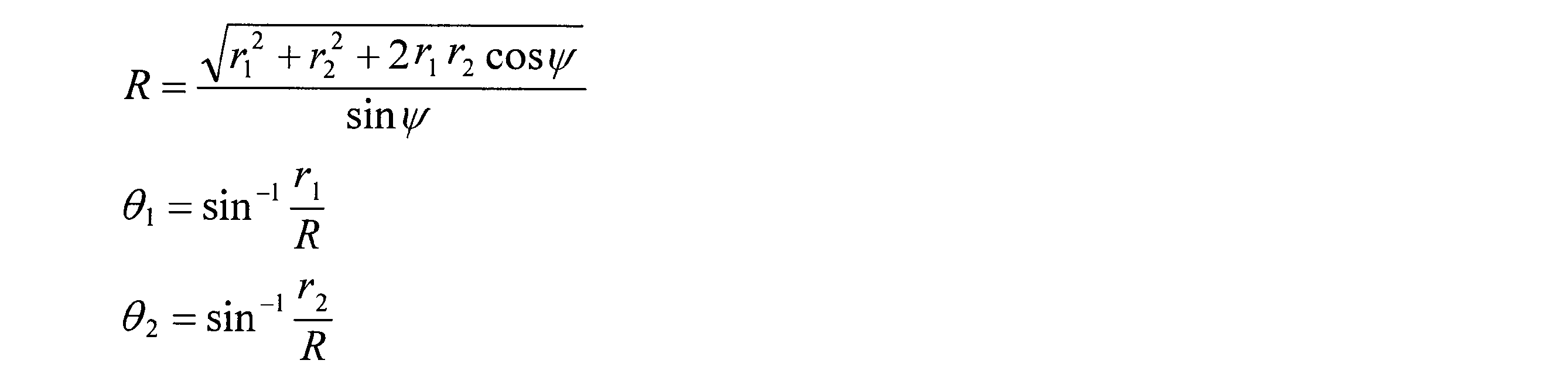
- the bottom surface radius r2 and the angle ⁇ formed by the rotating shaft 5 and the rotating shaft 6 are determined. From these values, the deployment radius R of the fan belt 3, the cone angle ⁇ 1 of the conical pulley 1, and the cone angle ⁇ 2 of the conical pulley 2 are determined so as to satisfy the following relationship.
- R, ⁇ 1, and ⁇ 2 are determined as follows.
- the deployment radius R ′ of the fan belt 4 is determined from the truncated cone bottom radius r1 ′ formed by the conical pulley 1 and the fan belt 4 and the truncated cone bottom radius r2 ′ formed by the cone pulley 2 and the fan belt 4 in the case of the fan belt 3. What is necessary is just to obtain
- the development radius R ′ of the fan belt 4 may be determined first so as not to overlap the fan belt 3, and the frustoconical bottom radii r 1 ′ and r 2 ′ may be determined by the following equations.
- the pulley is conical
- the belt is fan-shaped
- the conical pulleys are arranged so that the apexes of the conical pulleys coincide with each other, so that transmission of non-orthogonal axes is possible without twisting the belt.
- the fan belts 3 and 4 are sufficiently thin, it is possible to transmit multiple rotations approximately by increasing the belt center angle and wrapping multiple times. In reality, however, if the belts overlap, Because the radius changes by the thickness, accurate transmission is difficult.
- FIG. 2 shows a shape in which the fan belt of this embodiment is developed on a plane.
- the surface shape of the belt is assumed to be a flat belt.
- the fan belts 3 and 4 receive a force directed toward the distal ends of the conical pulleys 1 and 2 to prevent the belt from slipping laterally. It is necessary to take measures.
- the fan belts 3 and 4 may be V belts or V ribbed belts.
- a fan belt 10 is used in combination with a conical pulley as in the first embodiment.
- the sectional shape of the fan belt 10 is shown in FIG. Since a larger force is applied to the surface on the center side of the fan, the V shape is not symmetric, and it is preferable to have a cross-sectional shape in which the surface on the center side is closer to the vertical as shown in FIG.
- the conical pulley is provided with irregularities corresponding to the contact surface shape of the fan belt on the surface with the virtual conical surface as a reference. As shown in FIG. 2, the conical pulley 9 has a shape obtained by subtracting the contact surface shape of the fan belt 10 shown in FIG.
- FIG. 3 is a diagram schematically showing only the main part of the configuration of the third embodiment of the non-parallel shaft belt transmission mechanism of the present embodiment
- FIG. 3 (a) is a top view
- FIG. 3 (b) is a top view. It is a front view.
- 11 and 12 are main conical pulleys
- 17 and 18 are guide conical pulleys
- 13 is a fan ring belt.
- the main conical pulleys 11 and 12 and the guide conical pulleys 17 and 18 are arranged so as to be rotatable around the center lines of the respective virtual conical surfaces, with their vertices being coincident with each other.
- the rotation axes intersect at the vertices of the respective virtual conical surfaces.
- the fan belt can be formed into an annular shape having the same radius, and therefore, continuous multi-rotation transmission is possible.
- the conical angles of the main conical pulleys 11 and 12 are large, the development center angle of the fan-shaped belt 13 may exceed 2 ⁇ . Even in such a case, it can be realized by dividing the fan belt into a plurality of pieces and connecting them into a ring shape.
- An angle ⁇ formed by the rotation axis 16 is determined. From these values, the deployment radius R of the fan-shaped belt 13, the conical angle ⁇ 1 of the main conical pulley 11, and the conical angle ⁇ 2 of the main conical pulley 12 can be determined by the same equations as in the first embodiment. Further, the radius of the bottom of the truncated cone formed by the guide conical pulleys 17 and 18 and the fan annular belt 13 is determined.
- the frustoconical bottom radii of the guide conical pulleys 17 and 18 may be different, in this embodiment, both are set to r3 for simplicity.
- the cone angle ⁇ 3 of the guide conical pulleys 17 and 18 is obtained by the following equation.
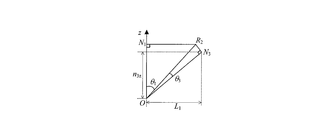
- the contact point between the bottom surface of the truncated cone of the main conical pulley 11 and the bottom surface of the truncated cone of the main conical pulley 12 is R1, and the bottom surface of the truncated cone of the main conical pulley 11 and the bottom surface of the truncated cone of the guide conical pulley 17 are in contact.
- the contact point is R2
- the contact point between the bottom of the truncated cone of the main conical pulley 12 and the bottom of the truncated cone of the guide cone pulley 17 is R3.
- a vector from point A to point B is described as “vector A ⁇ B”.
- the vertex of the conical pulley is the origin O, and the Z axis is taken in the direction of vector O ⁇ N1.
- the Y axis is taken in the direction of a straight line on the plane formed by the vector O ⁇ N1 and the vector O ⁇ N2 and perpendicular to the Z axis.
- the X axis is taken in the direction of the outer product vector of the vector O ⁇ N2 and the vector O ⁇ N1.
- the angle between the vector N1 ⁇ R1 and the vector N1 ⁇ R2 is ⁇ 1
- the angle between the vector N2 ⁇ R1 and the vector N2 ⁇ R3 is ⁇ 2
- the angle between the vector N3 ⁇ R1 and the vector N3 ⁇ R2 is ⁇ 3.
- the rotational axis direction of the guide conical pulley 17 can be determined if ⁇ 1 and ⁇ 2 can be determined. Further, the development center angle ⁇ of the fan-shaped belt 13 can be determined by the following equation if ⁇ 1, ⁇ 2, and ⁇ 3 can be determined.
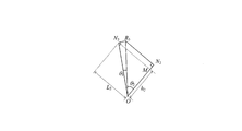
- FIG. 4 shows a cross section ON-N3-R2-N1. From the figure, the Z coordinate n3z of the point N3 and the distance L1 from the Z axis of the point N3 are respectively determined as follows.
- FIG. 5 shows a cross section ON-N2-R3-N3.
- a perpendicular foot drawn from the point N3 to the rotation axis of the main conical pulley 12 is defined as a point M.
- the magnitude h2 of the vector O ⁇ M and the magnitude L2 of the vector M ⁇ N3 are obtained as follows.
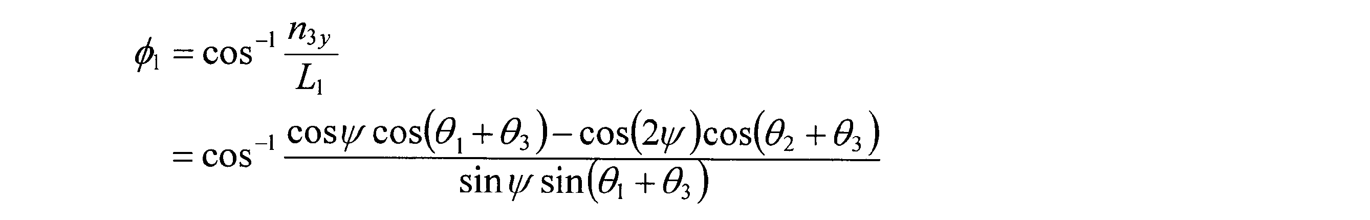
- FIG. 3B shows a projection of the vector M ⁇ N3 on the plane YZ. From the figure, the Y coordinate n3y and the Z coordinate n3z of the point N3 are obtained as follows.
- N2 is obtained as follows by deleting n3z from Equation (1) and Equation (3) and substituting Equation (2).
- ⁇ 1 is obtained as follows.
- n3x is obtained as follows.
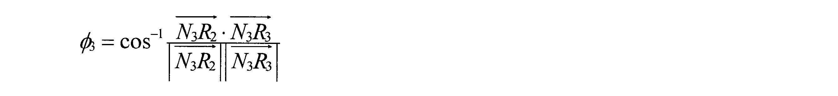
- ⁇ 3 is determined as follows.
- Such a non-parallel shaft belt transmission mechanism can transmit a non-parallel shaft that is lighter and less backlash than a bevel gear and has higher rigidity and durability than a wire transmission mechanism.
- FIG. 6 shows a shape in which the fan-shaped belt of this embodiment is developed on a plane.
- Reference numeral 20 denotes a fan-shaped belt, which is a timing belt having teeth only on one side. The surface with the teeth is the main conical pulley side, and the main conical pulley is a timing pulley with a groove that matches its shape.
- rotation in both directions can be transmitted without slipping the contact surface between the conical pulley and the fan-shaped belt.
- Two fan belts are connected by a line segment PP ′ and a line segment QQ ′ to form a fan annular belt 20.
- Such a shape is of course a shape that can be realized thanks to the flexibility of the belt.
- the development center angle of the fan-shaped belt 20 is ⁇ 1 + ⁇ 2.
- the teeth of the timing belt are widened toward the outside of the fan, so that the teeth of the fan belt are sandwiched in the groove of the conical pulley like a wedge and the force toward the tip of the conical pulley is applied. It plays the role of receiving, and no lateral shift occurs.
- the guide pulley side may be contacted with a conical surface without providing teeth.
- the frusto-conical bottom radius r3 of the guide conical pulley was previously determined, and the development center angle ⁇ of the fan annular belt 13 corresponding thereto was determined.
- r3 is not particularly limited as long as r3 is large enough to ensure sufficient durability of the fan-shaped belt and small enough not to interfere mechanically with other components.
- ⁇ needs to be determined so that the number of teeth of the belt becomes an integer. Therefore, it is better to first determine ⁇ and obtain r3 corresponding to it, but it is difficult to analytically obtain this calculation formula. In that case, the calculation for obtaining ⁇ from r3 as described above may be repeated using a computer until it converges with sufficient accuracy.
- FIG. 7 is a diagram showing the main part of the configuration of the fifth embodiment, FIG. 7 (a) is a front view, FIG. 7 (b) is a right side view, FIG. 7 (c) is a bottom view, and FIG. FIG.
- 21 and 22 are input conical pulleys
- 23 is a main conical pulley
- 24, 25, 26 and 27 are guide conical pulleys
- 28 is a fan-shaped belt.
- power is transmitted by only one fan annular belt 28.
- the fan-shaped belt 28 has a fan shape with a central angle exceeding 2 ⁇ , and has a ring shape.
- the input conical pulleys 21 and 22, the main conical pulley 23, and the guide conical pulleys 24, 25, 26 and 27 are adjacent to each other with their apexes coincident with each other, as in the second embodiment. Arrange as follows. That is, the rotation axes meet at the apex of each cone. However, a gap corresponding to the thickness of the fan annular belt 28 is opened. In this embodiment, the frustoconical bottom radii of the input conical pulley 21 and the input conical pulley 22 are made to coincide with each other, and their rotational axes are arranged on the same straight line.
- the rotation axis of the main conical pulley 23 is arranged so as to be orthogonal to these.
- the fan belt 28 is wound around the input conical pulleys 21, 22, the main conical pulley 23, and the guide conical pulleys 24, 25, 26, 27 as shown.
- the fan annular belt 28 is tensioned by being sandwiched between four guide conical pulleys.
- the conical pulley is arranged in this way, the belt can be formed into an annular shape having the same radius, and therefore, continuous multi-rotation transmission is possible.
- the fan annular belt 28 is, for example, a timing belt in which teeth are carved on contact surfaces with the input conical pulleys 21 and 22 and the main conical pulley 23.
- the timing belt By using the timing belt, rotation in both directions can be transmitted without slipping the contact surface between the main conical pulley and the fan-shaped belt.
- the conical pulley and the fan belt may be transmitted by friction like a flat belt or a V-belt.
- a part of the fan belt may be fixed to the conical pulley, but in this case, the movable range is limited to less than one rotation.
- the frustoconical bottom radius of the input conical pulleys 21 and 22 is r1
- the frustoconical bottom radius of the main conical pulley 23 is r2
- the guiding conical pulleys 24, 25, and 26. , 27 can be calculated as ⁇ 1, ⁇ 2, and ⁇ 3 in the same manner as in the second embodiment.
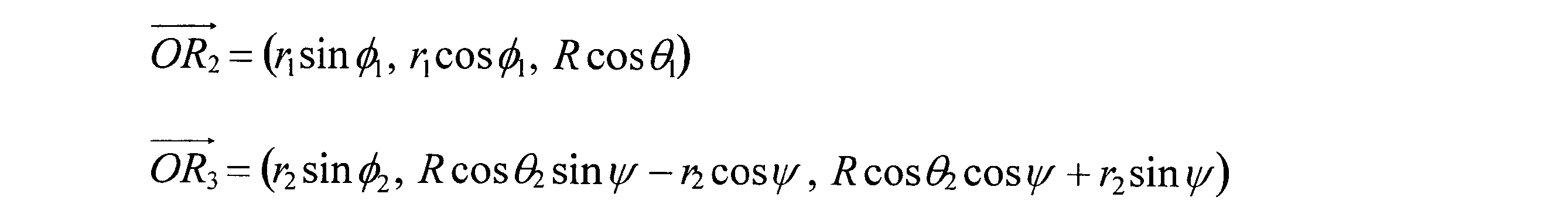
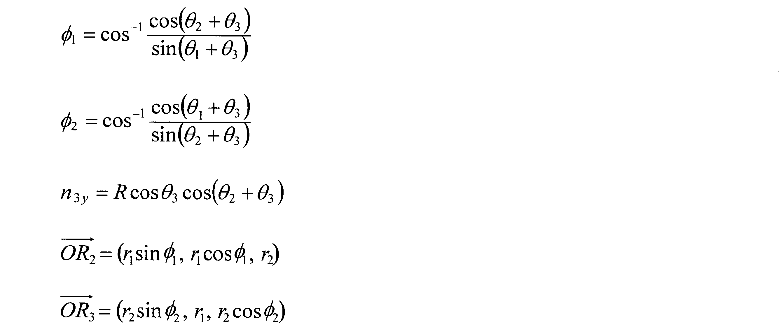
- the calculation formulas for ⁇ 2, n3y, vector O ⁇ R2, and vector O ⁇ R3 are simplified as follows.
- the development center angle ⁇ of the fan belt 28 can be determined from ⁇ 1, ⁇ 2 and ⁇ 3 by the following equation.
- the main conical pulley 23 is in contact with the fan-shaped belt 28 at two places, but it is necessary to make them mesh with each other without contradiction.
- the input conical pulleys 21 and 23 have the same shape and the number of tooth grooves is odd
- the number of teeth of the fan belt 28 must be odd
- the input conical pulleys 21 and 23 have the same shape and the number of tooth grooves is even. If so, the number of teeth of the fan-shaped belt 28 needs to be an even number.
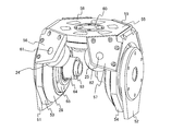
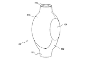
- FIG. 8 is an overall structural diagram including the support mechanism and actuator of the mechanism of this embodiment
- FIG. 9 is an exploded structural diagram thereof. For convenience of illustration, some parts are shown only on one side, but the parts not shown are also provided with the same parts in the front-rear and left-right symmetry. Only one side will be described below.
- reference numeral 51 denotes a fixed support disk which fixedly supports the hollow fixed support shaft 63 and the circular spline of the harmonic gear 67.
- the reduction gear is a type of harmonic gear 67 having two circular splines, but other types of harmonic gears and other reduction devices may be used.
- An outer rotor motor stator 66 is fixed to the hollow fixed support shaft 63.
- the outer rotor motor rotor 64 is supported so as to be rotatable around the pitch axis via a bearing.
- a wave generator serving as an input of the harmonic gear 67 is fixed to the outer rotor motor rotor 64.
- the input conical pulley 21 is fixed to another circular spline that is an output of the harmonic gear 67.
- the input conical pulley 21 is rotatably supported around the pitch axis via a main pulley support disk 65 and a cross roller bearing 68.
- the input conical pulley 21 is supported outside the outer rotor motor rotor 64, but of course, it may be supported by a fixed portion such as the hollow fixed support shaft 63. good.
- Reference numeral 61 denotes a guide pulley support shaft, which supports the guide conical pulley 24 via a bearing 70 so as to be rotatable around the central axis of the guide pulley support shaft 61.
- the guide pulley support shaft 61 is fixed to the small support frame 56.
- Four parts that are the same as those of the support frame small 56 are arranged at the front, rear, left, and right positions. These, the support frame sides 52 and 53, and the support frame top 55 are fixed integrally, and are supported rotatably around the pitch axis via bearings provided on the support frame sides 52 and 53, respectively. ing.
- An output shaft 60 is supported on a support frame 55 via a bearing 70 so as to be rotatable around a roll axis.
- the main conical pulley 23 is fixed to the output shaft 60 and outputs the power around the roll axis transmitted by the fan annular belt 28.
- Patent Document 1 In the prior art of Patent Document 1, four steps are required for the pulley in order to obtain a differential mechanism. However, in this embodiment, only one step is required, so that the size and weight can be reduced. In addition, since a belt is used, durability is higher than when a wire is used. Furthermore, in the prior art of Patent Document 1, it is possible to transmit only up to one rotation, but in the present embodiment, continuous multi-rotation transmission is possible. By applying this mechanism as an interference drive joint mechanism of a robot, a small and lightweight robot can be realized.
- FIG. 10 is a diagram showing the configuration of the sixth embodiment, in which FIG. 10 (a) is a front view, FIG. 10 (b) is a right side view, and FIG. 10 (c) is a perspective view.
- 33 and 34 are input conical pulleys
- 35 and 36 are main conical pulleys
- 37, 38, 40, 41, 42 and 44 are guide conical pulleys
- 31 and 32 are fan-shaped belts.
- the fan-shaped belts 31 and 32 are fan-shaped with a central angle exceeding 2 ⁇ and are circular.
- the input conical pulleys 33 and 34, the main conical pulleys 35 and 36, and the guide conical pulleys 37, 38, 40, 41, 42, and 44 are the center lines of the respective virtual conical surfaces as in the second and third embodiments. It is possible to rotate around it, and arrange them so that their vertices coincide with each other. That is, the rotation axes intersect at the vertices of the respective virtual conical surfaces.
- the frustoconical bottom radii of the input conical pulley 33 and the main conical pulley 34 are made to coincide with each other, and their rotational axes are arranged on the same straight line.
- the base cone radii of the main conical pulley 35 and the main conical pulley 36 are made to coincide with each other, and the rotation axes thereof are arranged on the same straight line.
- the rotation axes of the main conical pulley 35 and the main conical pulley 36 are arranged so as to be orthogonal to the rotation axes of the input conical pulley 33 and the main conical pulley 34.
- the fan belt 31 is wound around the input conical pulleys 33, 34, the main conical pulleys 35, 36, and the guide conical pulleys 37, 38, 41, 42 as shown in FIG.
- the fan annular belt 31 obtains tension by being held down by four guide conical pulleys.
- the fan-shaped belt 32 is arranged so as to be restrained by four guide conical pulleys at a symmetrical position in the front-rear direction.
- the conical pulley is arranged in this way, the belt can be formed into an annular shape having the same radius, and therefore, continuous multi-rotation transmission is possible.
- the fan belts 31 and 32 may be timing belts, for example, as in the second or third embodiment.
- the frustoconical bottom radius of the input conical pulleys 33 and 34 is r1
- the frustoconical bottom radius of the main conical pulleys 35 and 36 is r2. If the radius of the bottom of the truncated cone of the eight guide conical pulleys is set to r3, ⁇ 1, ⁇ 2, and ⁇ 3 can be calculated as in the second and third embodiments.
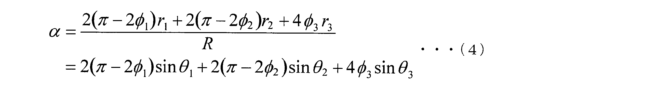
- the development center angle ⁇ of the conical pulley fan annular belts 31 and 32 can be determined from ⁇ 1, ⁇ 2 and ⁇ 3 by the following equation.
- an orthogonal shaft differential transmission that is lighter and less backlash than a bevel gear and has higher rigidity and durability than a wire transmission mechanism is possible.
- this transmission mechanism power is independently input to the input conical pulley 33 and the main conical pulley 34, and the main conical pulley 35 (or the main conical pulley 36) is fixed to the output shaft.
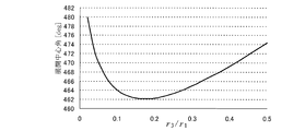
- FIG. 11 shows a numerical example of the development center angle calculated using Equation (4).
- the four main conical pulleys and the eight guide conical pulleys have the same shape.
- the development center angle in this case is determined by the ratio between the truncated cone bottom radius r1 of the main cone pulley and the truncated cone radius r3 of the guide cone pulley. From the figure, it can be seen that the center angle of expansion of the fan-shaped belt is suitably about 462 ° to 474 °. Assuming that the number of teeth of the main conical pulley is T, the tooth pitch p in the developed fan belt is expressed as follows by the developed central angle.
- the length of the fan-shaped belt (center expansion angle ⁇ ) is set to any one of these, and the ratio of r1 and r3 to obtain this length is obtained from FIG. 11 and r3 may be determined.
- the rotation axes of the main conical pulleys 35 and 36 are made to coincide with each other, but it is not necessary to make them coincide with each other, and three or more conical pulleys may be arranged so as to be orthogonal to the input conical pulleys 33 and 34. it can.
- the load per one fan annular belt can be reduced, but there is a problem that the weight of the mechanism becomes heavier, so it is often not a good idea to increase the load.
- the fan-shaped belt can be made into a simple circle depending on the dimensional condition, and the belt can be easily manufactured.
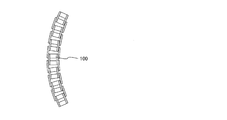
- FIG. 12 shows a chain used as the fan belt of this embodiment.
- a general chain can be seen as a small link connected in a rotatable manner around a parallel axis, but it can be used as a fan belt by angling this axis rather than parallel.
- the conical pulley may be a sprocket whose projection direction is perpendicular to the conical surface.
- FIG. 13 is a diagram showing a main part of the configuration of the ninth embodiment.
- This embodiment is an example in which a sliding support member is used instead of the guide conical pulleys 24 to 27 of the third embodiment.
- Other configurations are the same as those of the third embodiment.
- Reference numerals 80 and 81 are sliding support members, and the rear two are hidden in the drawing and are not shown in the figure, but four sliding support members having similar shapes are provided at symmetrical positions in the front-rear and left-right directions.
- the sliding support members 80 and 81 are fixed to members corresponding to the small support frames 56 to 59 of the third embodiment, and support the fan-shaped belt 28 in sliding contact.
- the shape of the contact surface with the fan annular belt 28 is a virtual conical surface.
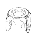
- FIG. 14 is an external view of the joint unit 136 of the present embodiment.
- Reference numeral 110 denotes a support structure with a cover in which a cover is fixed to the support frame sides 53 and 54, the support frame upper 55, and the support frame small 56 to 59.
- Reference numeral 101 denotes a support disk, which is obtained by fixing a cover for protecting cables to the fixed support disk 52 in FIG.
- Reference numeral 109 denotes an output body, which is fixed to the output shaft 60 of FIG.
- the support disk 101 is connected to the support base 103 via the hollow support arm 102.
- the support structure from the hollow fixed support shaft 63 to the support base 103 is connected in a hollow manner, and wiring can be passed through the inside.
- the wiring includes a motor power line for supplying power to the coil of the outer rotor motor stator 66, an encoder signal line for passing a signal from an encoder (not shown) to the controller, and the like.
- the other apparatus wiring which is wiring from apparatuses, such as another differential joint unit connected ahead of the output body 109 is also included.
- Other device wiring passes through the hollow portion of the output body 109 and into the hollow fixed support shaft 63. Since the wiring can be passed near the vertical and horizontal rotating shafts, the slack and pulling of the wiring are less likely to occur when the joint is operated, and durability during repeated operations can be improved.
- the support structure with cover 110 rotates around the horizontal axis around the support disk 101, and the output body 109 rotates around the vertical axis.
- the conveyed product attached to the tip of the output body 109 can be rotated around the horizontal axis and the vertical axis. Since these two output shafts are configured to be interference drive mechanisms, an output that is twice as much as the output of the motor alone can be generated at each shaft.
- the robot arm 150 includes a robot base 134 with a turning axis motor, joint units 131, 132, 133 to 133, and a hand 130.
- the robot base 134 with a turning axis motor fixes a robot arm 150 to a fixed surface (for example, a floor in a factory, etc.) 151 and a base (base) having a motor for rotating the entire robot arm 150 about a vertical axis. Stand).
- the joint units 131, 132, and 133 are coupled in series by coupling the output pair 109 and the support base 103, respectively.
- Reference numeral 130 denotes a hand, which is a work unit whose position and orientation are controlled by the robot arm and that performs tasks such as conveyance, assembly, welding, and painting. Since the present embodiment has such a configuration, it is possible to configure a 7-degree-of-freedom vertical articulated robot in which the maximum output is improved while the robot arm 150 is downsized (particularly slimmed).
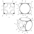
- FIG. 16 is a perspective view showing the shapes of the conical pulley and the fan belt of the eleventh embodiment.
- 161 is a sprocket conical pulley having a conical pulley provided with a protrusion 161a.
- the protrusions 161a are arranged at equal intervals.
- Reference numeral 163 denotes a fan belt with holes, which has holes corresponding to the protrusions 161a.
- the protrusion can mesh with the hole to prevent the belt from slipping.
- the shape of the hole is a circle, and the shape of the protrusion is a cylinder with a hemisphere at the tip, but these shapes are arbitrary, for example, the protrusion is a conical shape, the hole is connected to a rectangle or two circles
- the shape of the protrusion such as a long hole, may be a shape that meshes with it.
- the holed fan belt 163 may be a steel belt.
- Reference numeral 162 denotes a grooved conical pulley, which includes a groove 162a. A sectional view of the meshing portion is shown in FIG. By the groove 162a, interference between the protrusion 161a protruding from the holed fan belt 163 and the grooved pulley 162 can be avoided.
- the virtual conical surfaces of the main conical pulley and the input conical pulley are in contact with each other.
- the sprocket conical pulley of this embodiment is used as a main conical pulley or an input conical pulley and is arranged in this manner, the protrusion 161a interferes.
- the virtual conical surfaces of the main conical pulley and the input conical pulley may be arranged apart from each other.
- the virtual conical surfaces of the main conical pulley and the input conical pulley do not need to be in contact with each other, and each may be in contact with the virtual conical surface of the guide conical pulley.
- the virtual conical surfaces of the main conical pulley and the input conical pulley are arranged apart by an angle ⁇ , the dimension calculation is
- the calculation may be performed in the same manner as in the embodiment described above.
- the radius of the bottom of the truncated cone of the guide cone pulley is determined so that the central angle of the fan-shaped belt is an integral multiple of the pitch p of the teeth of the main cone pulley. If the virtual conical surface of the input conical pulley is spaced apart by an angle ⁇ , the radius of the bottom of the truncated cone of the guide conical pulley is determined appropriately in advance, and the unfolded central angle of the fan belt is an integral multiple of the meshing pitch.
- ⁇ may be determined so that
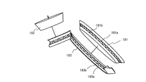
- FIG. 18 is a perspective view showing the shapes of the conical pulley and the fan belt of the twelfth embodiment.
- Reference numeral 181 denotes a timing conical pulley provided with a V groove 181a and a protrusion 181b on the conical pulley.
- the protrusions 181b are arranged at equal intervals.
- a timing fan belt 183 includes a V protrusion 183a corresponding to the V groove 181a and a recess 183b corresponding to the protrusion 181b.
- FIG. 19 shows a view separated so that the contact portion between the belt and the pulley can be seen.
- the belt portion of the timing fan belt 183 may be a steel belt, and the V groove 181a and the V protrusion 183a may be made of an elastic material such as urethane or rubber, and may be bonded to the steel belt.
- the contact surface between the timing fan belt 183 and the conical pulley 182 is flat, and the 182 is a normal conical pulley.
Landscapes
- Engineering & Computer Science (AREA)
- Mechanical Engineering (AREA)
- General Engineering & Computer Science (AREA)
- Robotics (AREA)
- Pulleys (AREA)
- Devices For Conveying Motion By Means Of Endless Flexible Members (AREA)
- Manipulator (AREA)
- Gears, Cams (AREA)
- Structure Of Belt Conveyors (AREA)
Abstract
平行でない軸に動力を伝動できる、軽量で、バックラッシがなく、耐久性の高い機構を実現する。また、軽量で、バックラッシがなく、耐久性の高い直交軸差動機構を備えたロボットを実現する。 円錐形のプーリと扇形のベルトを備える。複数の円錐プーリを仮想円錐面の頂点が一致し、仮想円錐面が接するように配置する。これを用いて直交軸差動機構とし、ロボットを構成する。
Description
本発明は、直交軸など平行でない軸に、ベルトを用いて動力を伝達する非平行軸ベルト伝動機構とそれを用いたロボットに関する。
平行でない軸に動力を伝達する非平行軸伝動機構は、ロボットの関節をはじめ、多くの機械に用いられている。
非平行軸伝動機構の中でも、直交軸伝動機構が特によく用いられ、差動機構とする例もある。
非平行軸伝動機構の中でも、直交軸伝動機構が特によく用いられ、差動機構とする例もある。
最も一般的な非平行軸伝動機構としては、傘歯車があるが、傘歯車は摩擦を抑えるためにある程度の隙間が必要であるためバックラッシが大きいことや、歯欠けが起こらないように剛性の高い材料を使用する必要があり、重量が重くなることなどが一般的な技術課題となっている。
この一般的な技術課題を解決するために、ワイヤを用いた非平行軸伝動機構が考案された(例えば、特許文献1参照)。
この一般的な技術課題を解決するために、ワイヤを用いた非平行軸伝動機構が考案された(例えば、特許文献1参照)。
ワイヤは引張り方向の力しか伝動できないため、本従来技術では、段差を設けた2個のプーリを、回転軸が直交するように配置し、2本のワイヤを逆向きに巻き、双方向の回転を伝動できるようにしている。また、ベルトを用いた非平行軸伝動機構も従来ある(例えば、非特許文献1参照)。
しかしながら、従来のワイヤを用いた非平行軸伝動機構は、一般のワイヤを用いた機構と同様に、ワイヤへの負荷が大きくなるためワイヤの信頼性の問題から産業用機器への適用が妨げられていた。また、従来の機構ではワイヤの端をそれぞれプーリに固定する必要があり、1回転するとワイヤが重なってしまうため、可動範囲が1回転に限られるという問題があった。
本発明はこのような課題に鑑みてなされたものであり、耐久性が高く、可動範囲の制限なく直交する軸に動力を伝達でき、差動機構としても用いることができる非平行軸ベルト伝動機構を提供することを目的とする。
上記課題を解決するため、本発明は、次のように構成した。
請求項1に記載の非平行軸伝動機構は、複数のプーリと、前記プーリをそれぞれ回転可能に支持する支持シャフトと、複数の前記プーリのうちのいずれかに入力された動力を回転軸が平行でない他のいずれかの前記プーリに伝える伝動媒体と、を有し、前記伝動媒体は、平面に展開した形状が扇形である扇ベルトとなっており、前記プーリは前記扇ベルトとの接触面に仮想円錐面を設定して前記仮想円錐面から前記扇ベルトの表面形状を差し引いた形状である円錐プーリとなっており、前記円錐プーリの回転軸は前記仮想円錐面がなす円錐の中心線となっており、複数の前記円錐プーリのうちの少なくとも2個はそれぞれの前記仮想円錐面の頂点の位置が一致するように配置されていることを特徴とするものである。
また、請求項2に記載の非平行軸伝動機構は、複数の前記円錐プーリのうちの少なくとも2個はそれぞれの前記仮想円錐面が接するように配置されており、前記扇ベルトは隣接する2個の前記円錐プーリの前記仮想円錐面の接線を境に表裏が逆の面で2個の前記円錐プーリと接しているとするものである。
また、請求項3に記載の非平行軸伝動機構は、前記扇ベルトは断面がV形または台形の突起を少なくとも1つ備えたVベルトであり、前記円錐プーリはそれに対応する溝を備えたものである。
また、請求項4に記載の非平行軸伝動機構は、前記扇ベルトのV形または台形の突起の形状は扇形の中心側の面とベルト面とのなす角が扇形の外側の面とベルト面とのなす角よりも小さい非対称形状であるものである。
また、請求項5に記載の非平行軸伝動機構は、前記扇ベルトはベルトの進行方向に複数の歯状突起を備えたタイミングベルトであり、前記円錐プーリはそれに対応する溝を備えたタイミングプーリであるものである。
また、請求項6に記載の非平行軸伝動機構は、前記扇ベルトのタイミングベルトの歯形状は扇形の外側ほど広くなるくさび形突起であり、前記円錐プーリはそれに対応する溝を備えたものである。
また、請求項7に記載の非平行軸伝動機構は、複数の前記円錐プーリのうちのいずれか2個をそれぞれ円錐プーリ1および円錐プーリ2とし、前記扇ベルトは一方の端を前記円錐プーリ1に固定されかつもう一方の端を前記円錐プーリ2に固定された両端固定扇ベルトであるものである。
また、請求項8に記載の非平行軸伝動機構は、隣接する2個の前記円錐プーリをそれぞれ円錐プーリAおよび円錐プーリBとし、前記円錐プーリAの前記仮想円錐面と前記円錐プーリBの前記仮想円錐面との接線を仮想円錐接線とし、前記両端固定扇ベルトを2本備え、一方の前記両端固定扇ベルトは前記仮想円錐面の頂点方向から見て時計回りに前記円錐プーリAに巻き付けられ前記仮想円錐接線を境に前記仮想円錐面の頂点方向から見て反時計回りに前記円錐プーリBに巻き付けられており、もう一方の前記両端固定ベルトは前記仮想円錐面の頂点方向から見て反時計回りに前記円錐プーリAに巻き付けられ前記仮想円錐接線を境に前記仮想円錐面の頂点方向から見て時計回りに前記円錐プーリBに巻き付けられているものである。
また、請求項9に記載の非平行軸伝動機構は、前記扇ベルトは扇形の両端を繋いで環状とした扇環状ベルトであるものである。
また、請求項10に記載の非平行軸伝動機構は、複数の前記円錐プーリのうちの2以上の整数n個の主円錐プーリと、2(n-1)個の案内円錐プーリとを備え、前記主円錐プーリおよび前記案内円錐プーリはそれぞれの前記仮想円錐面の頂点の位置が一致するように配置されており、前記案内円錐プーリは数珠繋ぎに連結された前記主円錐プーリの間に2個ずつそれぞれ2個の前記主円錐プーリに隣接するように配置されており、前記扇環状ベルトは内側の面で前記主円錐プーリと接しており外側の面で前記案内円錐プーリと接しているものである。
また、請求項11に記載の非平行軸伝動機構は、複数の前記円錐プーリのうちの2以上の整数n個の主円錐プーリと、2n個の案内円錐プーリとを備え、前記主円錐プーリおよび前記案内円錐プーリはそれぞれの前記仮想円錐面の頂点の位置が一致するように配置されており、前記案内円錐プーリは環状に連結された前記主円錐プーリの間に2個ずつそれぞれ2個の前記主円錐プーリに隣接するように配置されており、前記扇環状ベルトは内側の面で前記主円錐プーリと接しており外側の面で前記案内円錐プーリと接しているものである。
また、請求項12に記載の非平行軸伝動機構は、複数の前記円錐プーリのうちの2個の入力円錐プーリと、1以上の整数n個の主円錐プーリと、4n個の案内円錐プーリとを備え、前記入力円錐プーリと前記主円錐プーリと前記案内円錐プーリとはそれぞれの前記仮想円錐面の頂点の位置が一致するように配置されており、2個の前記入力円錐プーリの回転軸は同一直線上に配置され、前記主円錐プーリの回転軸は前記入力円錐プーリの回転軸と垂直になるように配置され、前記案内円錐プーリは前記主円錐プーリそれぞれに4つずつ接しておりかつ4つのうち2つが前記入力円錐プーリのうちの一方に接しており残り2つがもう一方の前記入力円錐プーリに接するように配置されているものである。
また、請求項13に記載の非平行軸伝動機構は、前記主円錐プーリはタイミングプーリであり、前記扇ベルトの展開中心角が主円錐プーリの歯溝ピッチの整数倍となるように前記案内円錐プーリの仮想円錐面の円錐台底面半径が設定されているものである。
また、請求項14に記載の非平行軸伝動機構は、前記案内円錐プーリをそれぞれ支持する前記支持シャフトおよび前記出力プーリを支持する前記支持シャフトを固定する支持フレームを備え、前記支持フレームは2個の前記入力円錐プーリの回転軸まわりに回転可能に支持されているものである。
また、請求項15に記載の非平行軸伝動機構は、前記扇ベルトを摺動接触支持する支持部材を少なくとも1つ備え、前記支持部材は前記扇ベルトとの接触面に仮想円錐面を設定して前記仮想円錐面から前記扇ベルトの表面形状を差し引いた形状である円錐形支持部材となっており、前記円錐形支持部材と複数の前記円錐プーリのうちのいずれかはそれぞれの前記仮想円錐面の頂点の位置が一致しておりかつ前記仮想円錐面が接するようにするように配置されており、前記扇ベルトは前記仮想円錐面の接線を境に表裏が逆の面で前記円錐プーリおよび前記円錐形支持部材と接しているとするものである。
また、請求項16に記載のロボットは、複数のアーム材と、前記アーム材とを旋回または回転可能に連結する関節部と、を有し、前記関節部には、請求項1乃至15記載の非平行軸伝動機構を有していることを特徴としている。
請求項1、16に記載の発明によると、平行でない軸に、ベルトを捻ることなく動力を伝動することができる。ベルトを用いるため、傘歯車を用いた場合に比べ軽量な材料を用いることができるため機構が軽量であり、バックラッシも少なく伝動することができる。また、ベルトを用いるため、ワイヤを用いた場合に比べ耐久性を高くすることができる。
また、請求項2に記載の発明によると、プーリを離さずに配置することができ、機構を小型化できる。
また、請求項3に記載の発明によると、ベルトが円錐の先端方向に滑ることなく動力を伝動できる。
また、請求項4に記載の発明によると、円錐の先端方向に向かう力を垂直に近い面で受けることができるため、ベルトがはずれにくくすることができ、ベルトの突起部を変形しにくくすることができるため、突起を小さくすることができ、ベルトを曲げやすくでき、ベルトの耐久性を高めることができる。
また、請求項5に記載の発明によると、強い力でも滑ることなく伝動することができる。
また、請求項6に記載の発明によると、ベルトが円錐の先端方向に滑ることなく動力を伝動できる。
また、請求項7に記載の発明によると、案内プーリ等を用いることなく、回転軸が平行でないプーリに単純な機構で動力を伝動することができる。
また、請求項8に記載の発明によると、案内プーリ等を用いることなく、回転軸が平行でない隣接したプーリに単純な機構で動力を伝動することができる。
また、請求項9に記載の発明によると、回転軸が平行でないプーリに両方向の回転の動力を連続的に伝動することができる。
また、請求項10に記載の発明によると、回転軸が平行でない数珠繋ぎに隣接する複数のプーリに両方向の回転の動力を連続的に伝動することができる。
また、請求項11に記載の発明によると、回転軸が平行でない環状に隣接する複数のプーリに両方向の回転の動力を連続的に伝動することができる。
また、請求項12に記載の発明によると、回転軸が同一直線上にある2つのプーリと、それと垂直な回転軸を持ち環状に隣接する複数のプーリに両方向の回転の動力を連続的に伝動することができる。
また、請求項13に記載の発明によると、扇環状ベルトをタイミングベルトとした場合でも、ベルトのたわみ等がなく、歯と溝を正しくかみ合わせることができ、回転軸平行でない隣接する複数のプーリに両方向の回転の動力を連続的に伝動することができる。
また、請求項14に記載の発明によると、ベルトを用いて軽量でバックラッシがなく耐久性が高い直交軸差動機構を実現することができる。ワイヤを用いた場合には差動機構にするためにプーリに4段の段差が必要であったが、1段にすることができるため小型軽量化でき、ベルトを用いてバックラッシがなく耐久性が高い直交軸差動機構を実現することができる。
また、請求項15に記載の発明によると、板金やプラスチックなどを用いることができ、小型軽量化でき、コストを低減できる。
また、請求項16に記載の発明によると、ベルトが円錐の先端方向や伝動方向に滑ることなく動力を伝動できる。
また、請求項17に記載の発明によると、剛性の高い扇ベルトを容易に製造できる。
また、請求項18に記載の発明によると、ベルトが円錐の先端方向や伝動方向に滑ることなく動力を伝動できる。
また、請求項19に記載の発明によると、プーリ同士が干渉することなく伝動できる。
また、請求項20に記載の発明によると、ベルトが円錐の先端方向や伝動方向に滑ることなく動力を伝動できる。
また、請求項21に記載の発明によると、タイミング扇ベルトを容易に製造できる。
[第1実施形態]
図1は、本発明の非平行軸ベルト伝動機構の最も単純な構成例の一つを示す三面図であり、図1(a)は正面図、図1(b)は右側面図、図1(c)は下面図である。理解しやすいように、主要部分のみを簡略的に示しているが、実際には支持機構等が必要である。図において、1、2は円錐プーリであり、3、4は扇ベルトである。円錐プーリとは、扇ベルトとの接触部分に仮想的に設定した円錐面を基準としてベルト厚みを差し引いた形状となっているプーリのことである。この仮想的に設定した円錐面を「仮想円錐面」と記述する。円錐プーリ1は回転軸5まわりに、円錐プーリ2は回転軸6まわりにそれぞれ回転可能となるように固定する。回転軸5および6は、それぞれの仮想円錐面の中心線となっている。
図1は、本発明の非平行軸ベルト伝動機構の最も単純な構成例の一つを示す三面図であり、図1(a)は正面図、図1(b)は右側面図、図1(c)は下面図である。理解しやすいように、主要部分のみを簡略的に示しているが、実際には支持機構等が必要である。図において、1、2は円錐プーリであり、3、4は扇ベルトである。円錐プーリとは、扇ベルトとの接触部分に仮想的に設定した円錐面を基準としてベルト厚みを差し引いた形状となっているプーリのことである。この仮想的に設定した円錐面を「仮想円錐面」と記述する。円錐プーリ1は回転軸5まわりに、円錐プーリ2は回転軸6まわりにそれぞれ回転可能となるように固定する。回転軸5および6は、それぞれの仮想円錐面の中心線となっている。
ここでは、便宜上「円錐」と記述しているが、円錐プーリ1および2の仮想円錐面は、もちろん実際には先端まで備えた円錐形である必要はなく、扇ベルトとの接触部分だけが円錐形であればよい。円錐プーリ1および2は、仮想円錐面の頂点を一致させて隣接するように配置する。すなわち、回転軸5と回転軸6はそれぞれの仮想円錐面の頂点で交わる。
扇ベルトとは、平面に展開した形状が扇形となるベルトである。ここでは、「扇形」と記述しているが、扇ベルトはもちろん実際には先端まで備えた扇形である必要はなく、「扇形」とは、図2に示すように、円弧を描くような帯状の形状を含む。上述のように円錐プーリを配置すると、一定の半径の扇形のベルトを2個のプーリにたるみなく巻き付けることができ、プーリが回転しても接触部が滑ることなく連続して動力を伝達できる。このようにすることで、プーリの回転軸が平行でない場合でも、ベルトによる動力伝達が可能となる。扇ベルトを平ベルトとし、ベルトの厚みの中央がなす円錐面を仮想円錐面7と設定している。
扇ベルトとは、平面に展開した形状が扇形となるベルトである。ここでは、「扇形」と記述しているが、扇ベルトはもちろん実際には先端まで備えた扇形である必要はなく、「扇形」とは、図2に示すように、円弧を描くような帯状の形状を含む。上述のように円錐プーリを配置すると、一定の半径の扇形のベルトを2個のプーリにたるみなく巻き付けることができ、プーリが回転しても接触部が滑ることなく連続して動力を伝達できる。このようにすることで、プーリの回転軸が平行でない場合でも、ベルトによる動力伝達が可能となる。扇ベルトを平ベルトとし、ベルトの厚みの中央がなす円錐面を仮想円錐面7と設定している。
従って円錐プーリ1および2は仮想円錐面7よりもベルト厚の半分だけ半径が小さい円錐形状である。円錐プーリ1および2は仮想円錐面が接するように配置するので、結果的に扇ベルト3および4の厚み分だけ隙間を空けて配置されることになる。以下では、図2に示すように、展開した際の扇ベルト外側の半径を「展開半径」と記述する。また、展開した場合の中心角を「展開中心角」と記述する。展開中心角はベルトの長さに相当する。本実施形態では、扇ベルト3および4の両端は円錐プーリ1および2にそれぞれ固定する。本実施形態では、扇ベルト3と扇ベルト4との干渉を防ぐため、位置をずらして配置する。このため、扇ベルト3の展開半径を扇ベルト4の展開半径より大きくする。
円錐プーリの仮想円錐面と扇ベルトの接触面を、円錐台の側面の一部とみなすことができる。このように見なすと、円錐プーリについても、扇ベルトとの接触面を平面に展開したときの展開半径と展開中心角を考えることができる。円錐プーリ1および2と扇ベルト3および4との接触部分は、展開半径がそれぞれ一致するような形状とする。以下では、この円錐台の底面の半径を「円錐台底面半径」と記述する。また、円錐の母線と回転軸とのなす角を「円錐角」と記述する。本実施形態のベルト伝動機構の幾何学的な寸法の設計においては、まず始めに、円錐プーリ1と扇ベルト3とがなす円錐台底面半径r1、円錐プーリ2と扇ベルト3とがなす円錐台底面半径r2、および回転軸5と回転軸6とがなす角ψを決定する。これらの値より、扇ベルト3の展開半径R、円錐プーリ1の円錐角θ1、円錐プーリ2の円錐角θ2は、次のような関係を満たすように決定する。

すなわち、これを解いて、R、θ1、θ2を次のように決定する。
扇ベルト4の展開半径R’は、円錐プーリ1と扇ベルト4とがなす円錐台底面半径r1’、円錐プーリ2と扇ベルト4とがなす円錐台底面半径r2’から扇ベルト3の場合と同様に求めればよい。ただし、円錐台底面半径r1’とr2’との比は、r1とr2との比と等しくなるように決定する。あるいは、先に扇ベルト3と重ならないように扇ベルト4の展開半径R’を決定し、円錐台底面半径r1’とr2’を次式により決定しても良い。

本実施形態では、プーリを円錐形とし、ベルトを扇形とし、円錐プーリの頂点が一致するように配置したことにより、ベルトをねじらずに非直交軸の伝動が可能となっている。
本実施形態の機構の動作を以下に説明する。円錐プーリ1が回転軸5まわりに上面から見て時計回りに回転すると、扇ベルト3が巻き取られ、円錐プーリ2が回転軸6まわりに上面から見て反時計回りに回転する。その際、扇ベルト4は円錐プーリ2に巻き取られるため、緩み等が生じることはない。円錐プーリ1が回転軸5まわりに上面から見て反時計回りに回転すると、扇ベルト4が巻き取られ、円錐プーリ2が回転軸6まわりに上面から見て時計回りに回転する。このようにして回転軸5の回転を、平行でない回転軸6に伝動することができる。このとき、r1とr2の比により減速あるいは増速される。
ただし、本実施形態では、扇ベルト3および4の両端を固定しているため、せいぜい1回転しか伝動できない。r1≦r2であるとすると、扇ベルト3および4の展開中心角αは以下のようにすると、小さい方のプーリすなわち円錐プーリ1が約1回転する範囲まで伝動できる。
ただし、本実施形態では、扇ベルト3および4の両端を固定しているため、せいぜい1回転しか伝動できない。r1≦r2であるとすると、扇ベルト3および4の展開中心角αは以下のようにすると、小さい方のプーリすなわち円錐プーリ1が約1回転する範囲まで伝動できる。

r1=r2のときは、θ1=π/4となるので、以下のようになる。

扇ベルト3および4が十分に薄いとすればベルトの展開中心角を大きくし、複数回巻き付けておくことで近似的に多回転の伝動が可能であるが、実際にはベルトが重なるとベルトの厚み分だけ半径が変化するため、精度のよい伝動は難しい。
[第2実施形態]
本実施形態では、扇ベルトをVリブドベルトとした場合の例について説明する。本実施形態の扇ベルトを平面に展開した形状を図2に示す。第1実施形態では、ベルトの表面形状は平ベルトを想定して説明したが、実際には扇ベルト3および4は円錐プーリ1および2の先端方向に向かう力を受けるため、ベルトの横ずれを防止する対策が必要である。これは、例えば扇ベルト3および4を、VベルトやVリブドベルトとすればよい。10は扇ベルトであり、第1実施形態と同様に円錐プーリと組み合わせて用いる。
本実施形態では、扇ベルトをVリブドベルトとした場合の例について説明する。本実施形態の扇ベルトを平面に展開した形状を図2に示す。第1実施形態では、ベルトの表面形状は平ベルトを想定して説明したが、実際には扇ベルト3および4は円錐プーリ1および2の先端方向に向かう力を受けるため、ベルトの横ずれを防止する対策が必要である。これは、例えば扇ベルト3および4を、VベルトやVリブドベルトとすればよい。10は扇ベルトであり、第1実施形態と同様に円錐プーリと組み合わせて用いる。
扇ベルト10の断面形状を図2に示す。扇の中心側の面により大きな力がかかるため、V形状を対称とはせずに、図2に示すように中心側の面をより垂直に近づけた断面形状とするとよい。扇ベルトをタイミングベルトやVベルトなどとした場合、円錐プーリは、仮想円錐面を基準として扇ベルトの接触面形状に対応する凹凸を表面に設ける。図2に示すように、円錐プーリ9は仮想円錐面8から図2に示す扇ベルト10の接触面形状を差し引いた形状とする。
[第3実施形態]
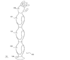
図3は、本実施形態の非平行軸ベルト伝動機構の第3実施形態の構成について、主要部分のみを簡略に示した図であり、図3(a)は上面図、図3(b)は正面図である。図において、11、12は主円錐プーリであり、17、18は案内円錐プーリであり、13は扇環状ベルトである。本実施形態では、扇ベルトは1本のみであり、環状である。第1実施形態と同様に、主円錐プーリ11、12および案内円錐プーリ17、18は、それぞれの仮想円錐面の中心線まわりに回転可能とし、頂点を一致させて隣接するように配置する。
図3は、本実施形態の非平行軸ベルト伝動機構の第3実施形態の構成について、主要部分のみを簡略に示した図であり、図3(a)は上面図、図3(b)は正面図である。図において、11、12は主円錐プーリであり、17、18は案内円錐プーリであり、13は扇環状ベルトである。本実施形態では、扇ベルトは1本のみであり、環状である。第1実施形態と同様に、主円錐プーリ11、12および案内円錐プーリ17、18は、それぞれの仮想円錐面の中心線まわりに回転可能とし、頂点を一致させて隣接するように配置する。
すなわち、回転軸はそれぞれの仮想円錐面の頂点で交わる。このように円錐プーリを配置すると、扇ベルトを同じ半径の環状にすることができるため、連続多回転の伝動が可能である。ただし、主円錐プーリ11および12の円錐角が大きい場合、扇環状ベルト13の展開中心角は2πを超える場合がある。このような場合でも、扇ベルトを複数本に分けて製造し、繋ぎ合わせて環状にすることで実現可能である。
本実施形態でも、まず始めに、主円錐プーリ11と扇環状ベルト13とがなす円錐台底面半径r1、主円錐プーリ12と扇環状ベルト13とがなす円錐台底面半径r2、および回転軸15と回転軸16とがなす角ψを決定する。これらの値より、扇環状ベルト13の展開半径R、主円錐プーリ11の円錐角θ1、主円錐プーリ12の円錐角θ2は第1実施形態と同様の式で決定できる。また、案内円錐プーリ17および18と扇環状ベルト13とがなす円錐台底面半径を決定する。案内円錐プーリ17および18の円錐台底面半径は異なっていても良いが、本実施形態では、簡単のため、どちらもr3とする。このとき、案内円錐プーリ17および18の円錐角θ3は、次式で求められる。

以下では、本実施形態で案内円錐プーリ17および18の回転軸の角度、および扇環状ベルトの展開中心角の決定方法を説明する。案内円錐プーリ17と18を同じ形状とした場合、回転軸の角度は対称な位置となるので、案内円錐プーリ17についての算出方法のみ述べる。主円錐プーリ11、12、および17の円錐台底面と回転軸との交点をそれぞれN1、N2、N3とする。また、本実施例では、主円錐プーリ11の円錐台底面と主円錐プーリ12の円錐台底面との接点をR1、主円錐プーリ11の円錐台底面と案内円錐プーリ17の円錐台底面とは接しており、その接点をR2、主円錐プーリ12の円錐台底面と案内円錐プーリ17の円錐台底面との接点をR3とする。以下では、点Aから点Bへ向かうベクトルを「ベクトルA→B」のように記述する。円錐プーリの頂点を原点Oとし、ベクトルO→N1の方向にZ軸をとる。
また、ベクトルO→N1とベクトルO→N2とがなす平面上にありZ軸と垂直な直線の方向にY軸をとる。ベクトルO→N2とベクトルO→N1との外積ベクトルの方向にX軸をとる。ベクトルN1→R1とベクトルN1→R2とのなす角をφ1、ベクトルN2→R1とベクトルN2→R3とのなす角をφ2、ベクトルN3→R1とベクトルN3→R2とのなす角をφ3とする。点N3は平面O-N1-R2上にあり、かつ、平面O-N2-R3上にあるので、φ1およびφ2が決定できれば案内円錐プーリ17の回転軸方向を決定できる。また、扇環状ベルト13の展開中心角αはφ1、φ2およびφ3が決定できれば次式により決定できる。

図4に断面O-N3-R2-N1を示す。図より、点N3のZ座標n3z、および点N3のZ軸からの距離L1は、それぞれ以下のように求められる。
図5に断面O-N2-R3-N3を示す。点N3から主円錐プーリ12の回転軸に下ろした垂線の足を点Mとする。図より、ベクトルO→Mの大きさh2、およびベクトルM→N3の大きさL2は、それぞれ以下のように求められる。
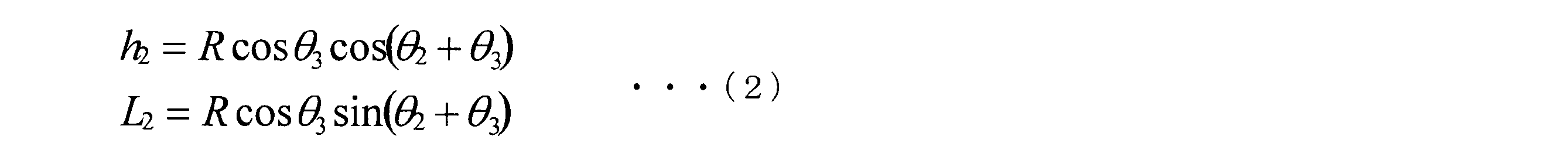
図3(b)に平面YZにベクトルM→N3を射影した図を示す。図より、点N3のY座標n3yおよびZ座標n3zは以下のように求められる。
数式(1)および数式(3)よりn3zを消去し、数式(2)を代入すればφ2を以下のように求められる。

図3(a)より、φ1は以下のように求められる。
また、図3(a)より、n3xは以下のように求められる。
以上で、点N3の座標が得られた。図3より点R2および点R3の座標は以下のように求められる。
点N3、点R2、点R3の座標が得られたので、以下のようにφ3を決定する。
以上で案内円錐プーリの回転軸方向および扇環状ベルト13の展開中心角が得られ、非平行軸のベルト伝動機構が実現できた。このような非平行軸ベルト伝動機構により、傘歯車に比べ軽量でバックラッシがなく、ワイヤ伝動機構に比べ剛性や耐久性が高い非平行軸の伝動が可能である。
[第4実施形態]
本実施形態では、扇環状ベルトをタイミングベルトとした場合の例について説明する。本実施形態の扇環状ベルトを平面に展開した形状を図6に示す。20は扇環状ベルトであり、片面にのみ歯を備えたタイミングベルトである。歯を備えた面を主円錐プーリ側とし、主円錐プーリをその形状に合わせた溝を備えたタイミングプーリとする。タイミングベルトにすることで、円錐プーリと扇環状ベルトとの接触面が滑ることなく、両方向の回転を伝達できる。2枚の扇ベルトを線分PP'と線分QQ'で繋いで扇環状ベルト20する。このような形状はもちろんベルトが可撓性であるおかげで実現可能な形状である。この場合の扇環状ベルト20の展開中心角はα1+α2となる。タイミングベルトの歯形状を、図6に示すように扇の外側ほど広がった形状とすることにより、扇ベルトの歯が円錐プーリの溝にくさびのように挟まって円錐プーリの先端方向に向かう力を受ける役割を果たし、横ずれが生じなくなる。案内プーリ側は歯を備えずに円錐面で接触すればよい。
本実施形態では、扇環状ベルトをタイミングベルトとした場合の例について説明する。本実施形態の扇環状ベルトを平面に展開した形状を図6に示す。20は扇環状ベルトであり、片面にのみ歯を備えたタイミングベルトである。歯を備えた面を主円錐プーリ側とし、主円錐プーリをその形状に合わせた溝を備えたタイミングプーリとする。タイミングベルトにすることで、円錐プーリと扇環状ベルトとの接触面が滑ることなく、両方向の回転を伝達できる。2枚の扇ベルトを線分PP'と線分QQ'で繋いで扇環状ベルト20する。このような形状はもちろんベルトが可撓性であるおかげで実現可能な形状である。この場合の扇環状ベルト20の展開中心角はα1+α2となる。タイミングベルトの歯形状を、図6に示すように扇の外側ほど広がった形状とすることにより、扇ベルトの歯が円錐プーリの溝にくさびのように挟まって円錐プーリの先端方向に向かう力を受ける役割を果たし、横ずれが生じなくなる。案内プーリ側は歯を備えずに円錐面で接触すればよい。
第3実施形態では、先に案内円錐プーリの円錐台底面半径r3を決定し、それに対応する扇環状ベルト13の展開中心角αを求めた。しかし、r3は、扇環状ベルトの耐久性が十分確保できる程度以上に大きく、他の部品と機構的に干渉しない程度以下に小さければ、特にどのような大きさでも構わない場合が多い。一方、扇環状ベルトをタイミングベルトとした場合、αはベルトの歯数が整数となるように決定する必要がある。そのため、先にαを決定し、それに対応するr3を求める方がよいのであるが、この計算式を解析的に求めるのは困難である。その場合は、計算機を用いて、上述のようなr3からαを求める計算を、十分な精度に収束するまで繰り返して求めればよい。
[第5実施形態]
図7は第5実施形態の構成の主要部分を示す図あり、図7(a)は正面図、図7(b)は右側面図、図7(c)は下面図、図7(d)は斜視図である。図において、21、22は入力円錐プーリ、23は主円錐プーリ、24、25、26、27は案内円錐プーリ、28は扇環状ベルトとなっている。本実施形態では、1本の扇環状ベルト28のみで動力を伝動する。扇環状ベルト28は、中心角が2πを超える扇形で、環状である。入力円錐プーリ21、22、主円錐プーリ23、および案内円錐プーリ24、25、26、27は、第2実施形態と同様に、それぞれの中心線まわりに回転可能とし、頂点を一致させて隣接するように配置する。すなわち、回転軸はそれぞれの円錐の頂点で交わる。ただし、扇環状ベルト28の厚み分の隙間を空ける。本実施形態では、入力円錐プーリ21と入力円錐プーリ22との円錐台底面半径を一致させ、その回転軸を同一直線上に対向させて配置する。
図7は第5実施形態の構成の主要部分を示す図あり、図7(a)は正面図、図7(b)は右側面図、図7(c)は下面図、図7(d)は斜視図である。図において、21、22は入力円錐プーリ、23は主円錐プーリ、24、25、26、27は案内円錐プーリ、28は扇環状ベルトとなっている。本実施形態では、1本の扇環状ベルト28のみで動力を伝動する。扇環状ベルト28は、中心角が2πを超える扇形で、環状である。入力円錐プーリ21、22、主円錐プーリ23、および案内円錐プーリ24、25、26、27は、第2実施形態と同様に、それぞれの中心線まわりに回転可能とし、頂点を一致させて隣接するように配置する。すなわち、回転軸はそれぞれの円錐の頂点で交わる。ただし、扇環状ベルト28の厚み分の隙間を空ける。本実施形態では、入力円錐プーリ21と入力円錐プーリ22との円錐台底面半径を一致させ、その回転軸を同一直線上に対向させて配置する。
主円錐プーリ23の回転軸はこれらと直交するように配置する。扇環状ベルト28は、入力円錐プーリ21、22、主円錐プーリ23、および案内円錐プーリ24、25、26、27のまわりに、図示したように巻く。扇環状ベルト28は、4つの案内円錐プーリで挟みつけることで張力を得ている。このように円錐プーリを配置すると、ベルトを同じ半径の環状にすることができるため、連続多回転の伝動が可能である。本実施形態では、扇環状ベルト28は、例えば入力円錐プーリ21、22、および主円錐プーリ23との接触面に歯を刻んだタイミングベルトとする。タイミングベルトにすることで、主円錐プーリと扇環状ベルトとの接触面が滑ることなく、両方向の回転を伝達できる。もちろん、円錐プーリと扇ベルトは平ベルトやVベルトのようにして、摩擦によって伝動しても良い。あるいは第1実施形態と同様に、扇ベルトの一部を円錐プーリに固定しても良いが、その場合は可動範囲が1回転未満に制限される。
入力円錐プーリ21と22は対称な形状とすればよいため、入力円錐プーリ21、22の円錐台底面半径をr1、主円錐プーリ23の円錐台底面半径をr2、案内円錐プーリ24、25、26、27の円錐台底面半径をr3とおけば、第2実施形態と同様にφ1、φ2、φ3が計算できる。ただし、本実施形態では入力円錐プーリ21と23の回転軸のなす角、および入力円錐プーリ22と23の回転軸のなす角がそれぞれ直角であるため、ψ=π/2とおけば、φ1、φ2、n3y、ベクトルO→R2、ベクトルO→R3の算出式が以下のように簡単になる。
扇環状ベルト28の展開中心角αはφ1、φ2およびφ3より次式で決定できる。
ここで、主円錐プーリ23は2箇所で扇環状ベルト28に接しているが、それらが互いに矛盾無く噛み合うようにする必要がある。例えば入力円錐プーリ21と23が同一形状で歯溝数が奇数であれば、扇環状ベルト28の歯数も奇数である必要があり、入力円錐プーリ21と23が同一形状で歯溝数が偶数であれば、扇環状ベルト28の歯数も偶数である必要がある。
このような直交軸差動ベルト伝動機構により、傘歯車に比べ軽量でバックラッシがなく、ワイヤ伝動機構に比べ剛性や耐久性が高い直交軸差動伝動が可能である。この伝動機構は、入力円錐プーリ21と入力円錐プーリ22それぞれに独立に動力を入力し、主円錐プーリ23を出力シャフトに固定して用いる。
図8は本実施形態の機構の支持機構やアクチュエータを含めた全体の構造図であり、図9はその分解構造図である。図の都合により、片側のみしか示されていない部品もあるが、図示されていない部分も、前後および左右対称に同じ部品を備えている。以下では、片側のみ説明する。また、以下では、入力円錐プーリ21および入力円錐プーリ22の回転軸をピッチ軸、主円錐プーリ23の回転軸をロール軸と記述する。図において、51は固定支持円盤であり、中空固定支持シャフト63、およびハーモニックギヤ67のサーキュラスプラインを固定支持している。
図8は本実施形態の機構の支持機構やアクチュエータを含めた全体の構造図であり、図9はその分解構造図である。図の都合により、片側のみしか示されていない部品もあるが、図示されていない部分も、前後および左右対称に同じ部品を備えている。以下では、片側のみ説明する。また、以下では、入力円錐プーリ21および入力円錐プーリ22の回転軸をピッチ軸、主円錐プーリ23の回転軸をロール軸と記述する。図において、51は固定支持円盤であり、中空固定支持シャフト63、およびハーモニックギヤ67のサーキュラスプラインを固定支持している。
本実施形態では、減速機にはサーキュラースプラインを2枚備えたタイプのハーモニックギヤ67を想定しているが、他のタイプのハーモニックギヤや他の減速機を用いても良い。中空固定支持シャフト63にはアウターロータモータ固定子66が固定されている。アウターロータモータ回転子64は、ベアリングを介してピッチ軸まわりに回転可能に支持される。ハーモニックギヤ67の入力となるウェーブジェネレータはアウターロータモータ回転子64に固定される。ハーモニックギヤ67の出力となるもう1つのサーキュラースプラインには、入力円錐プーリ21を固定する。入力円錐プーリ21は主プーリ支持円盤65およびクロスローラベアリング68を介して、ピッチ軸まわりに回転可能に支持する。本実施形態では、機構全体の寸法を小型化するために、入力円錐プーリ21をアウターロータモータ回転子64の外側で支持しているが、もちろん中空固定支持シャフト63など固定部分で支持しても良い。
61は案内プーリ支持シャフトであり、ベアリング70を介して案内円錐プーリ24を案内プーリ支持シャフト61の中心軸周りに回転可能に支持している。案内プーリ支持シャフト61は支持フレーム小56に固定されている。支持フレーム小56と同様の部品が前後左右対象な位置に4つ配置されている。これらと、支持フレーム横52および53と、支持フレーム上55とは一体に固定されており、支持フレーム横52および53にそれぞれ備えたベアリングを介してピッチ軸まわりにこれら全体が回転可能に支持されている。60は出力シャフトであり、支持フレーム上55にベアリング70を介してロール軸まわりに回転可能に支持されている。出力シャフト60には主円錐プーリ23が固定されており、扇環状ベルト28によって伝えられたロール軸まわりの動力を出力する。
本実施形態の動作を以下に説明する。入力円錐プーリ21と入力円錐プーリ22を同じ方向に回転させた場合、それらのトルクの和が出力シャフト60をピッチ軸周りに回転させる力として伝えられる。例えば、入力円錐プーリ21と入力円錐プーリ22を図の右からみて反時計回りに回転させた場合。扇環状ベルト28、案内円錐プーリ24および25、ベアリング69、案内プーリ支持シャフト61および62を介して支持フレーム小56および57に伝わり、出力シャフト60は、支持フレーム横51および52、支持フレーム上55、ベアリング70とともにこれらと一体となって、ピッチ軸周りに回転する。一方、入力円錐プーリ21と入力円錐プーリ22の回転トルクに差があった場合、その差に相当するトルクが扇環状ベルト28によって伝達され、出力シャフト60をロール軸まわりに回転させるトルクとなる。ただし、この機構の回転方向は傘歯車による差動機構とは逆になる。
特許文献1の従来技術では、差動機構にするためにプーリに4段の段差が必要であったが、本実施形態では1段でよいため、小型軽量化が可能である。また、ベルトを用いるのでワイヤを用いた場合に比べ、耐久性が高い。さらに、特許文献1の従来技術では、せいぜい1回転までしか伝動できないが、本実施形態では連続多回転の伝動が可能である。本機構をロボットの干渉駆動関節機構として適用し、小形軽量なロボットを実現可能である。
[第6実施形態]
図10は第6実施形態の構成を示す図あり、図10(a)は正面図、図10(b)は右側面図、図10(c)は斜視図である。図において、33、34は入力円錐プーリ、35、36は主円錐プーリ、37、38、40、41、42、44は案内円錐プーリ、31および32は扇環状ベルトとなっている。図では隠れているものもあるが、案内円錐プーリは8個あり、前後左右対称な位置に配置されている。本実施形態では、扇環状ベルト31と32の2本の扇環状ベルトを用いて動力を伝動する。扇環状ベルトはどちらか一方のみでも差動機構として動作させることができるが、2本用いることでベルトにかかる負荷を分散でき、より大きい負荷に耐えられる。あるいは、同じ負荷トルクを発生させたい場合に、それぞれのベルトを細くできる。扇環状ベルト31および32は、中心角が2πを超える扇形で、環状である。
図10は第6実施形態の構成を示す図あり、図10(a)は正面図、図10(b)は右側面図、図10(c)は斜視図である。図において、33、34は入力円錐プーリ、35、36は主円錐プーリ、37、38、40、41、42、44は案内円錐プーリ、31および32は扇環状ベルトとなっている。図では隠れているものもあるが、案内円錐プーリは8個あり、前後左右対称な位置に配置されている。本実施形態では、扇環状ベルト31と32の2本の扇環状ベルトを用いて動力を伝動する。扇環状ベルトはどちらか一方のみでも差動機構として動作させることができるが、2本用いることでベルトにかかる負荷を分散でき、より大きい負荷に耐えられる。あるいは、同じ負荷トルクを発生させたい場合に、それぞれのベルトを細くできる。扇環状ベルト31および32は、中心角が2πを超える扇形で、環状である。
入力円錐プーリ33、34、主円錐プーリ35、36、および案内円錐プーリ37、38、40、41、42、44は、第2及び第3実施形態と同様に、それぞれの仮想円錐面の中心線まわりに回転可能とし、頂点を一致させて隣接するように配置する。すなわち、回転軸はそれぞれの仮想円錐面の頂点で交わる。本実施形態では、入力円錐プーリ33と主円錐プーリ34との円錐台底面半径を一致させ、その回転軸を同一直線上に対向させて配置する。さらに、主円錐プーリ35と主円錐プーリ36の円錐台底面半径を一致させ、その回転軸を同一直線上に対向させて配置する。主円錐プーリ35および主円錐プーリ36の回転軸は、入力円錐プーリ33および主円錐プーリ34の回転軸と直交するように配置する。扇環状ベルト31は、入力円錐プーリ33、34、主円錐プーリ35、36、および案内円錐プーリ37、38、41、42のまわりに、図7(a)示したように巻く。
扇環状ベルト31は、4つの案内円錐プーリで抑えつけることで張力を得ている。扇環状ベルト32は、これと前後対称の位置に同様に4つの案内円錐プーリで抑えつけるように配置する。このように円錐プーリを配置すると、ベルトを同じ半径の環状にすることができるため、連続多回転の伝動が可能である。扇環状ベルト31および32は、第2又は第3実施形態と同様に、例えばタイミングベルトとすればよい。
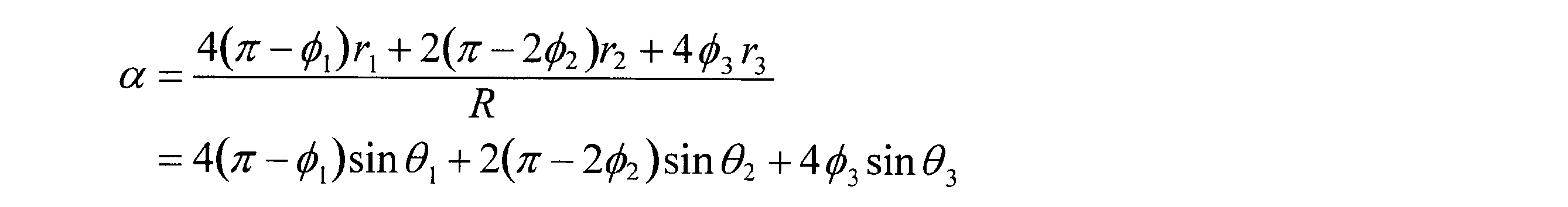
入力円錐プーリ33と34、主円錐プーリ35、36は対称な形状とすればよいため、入力円錐プーリ33、34の円錐台底面半径をr1、主円錐プーリ35、36の円錐台底面半径をr2、8個の案内円錐プーリの円錐台底面半径をr3とおけば、第2及び第3実施形態と同様にφ1、φ2、φ3が計算できる。円錐プーリ扇環状ベルト31および32の展開中心角αは、φ1、φ2およびφ3より次式で決定できる。
このような直交軸差動ベルト伝動機構により、傘歯車に比べ軽量でバックラッシがなく、ワイヤ伝動機構に比べ剛性や耐久性が高い直交軸差動伝動が可能である。この伝動機構は、入力円錐プーリ33と主円錐プーリ34それぞれに独立に動力を入力し、主円錐プーリ35(または主円錐プーリ36)を出力シャフトに固定して用いる。
このような構造とすると、片側から案内円錐プーリを4つ取り外すだけで扇環状ベルトを取り外すことができ、メンテナンスがしやすい。
このような構造とすると、片側から案内円錐プーリを4つ取り外すだけで扇環状ベルトを取り外すことができ、メンテナンスがしやすい。
図11に数式(4)を用いて計算した展開中心角の数値例を示す。4つの主円錐プーリと8つの案内円錐プーリはそれぞれ同じ形状とする。この場合の展開中心角は、主円錐プーリの円錐台底面半径r1と案内円錐プーリの円錐台底面半径r3との比によって決まる。図より、扇環状ベルトの展開中心角は462°から474°程度が適当であることが分かる。主円錐プーリの歯数をTとすると、展開した扇ベルトでは歯のピッチpは展開中心角で表すと以下のようになる。

扇ベルトの長さはpの整数倍である必要がある。歯数Tを50とすれば、p=5.09であり、扇ベルトの長さは、歯数91のとき463.3°、歯数92のとき468.4°、歯数93のとき473.5°となり、それ以外では適当な長さにならない。扇環状ベルトの長さ(中心展開角α)をこのいずれかとし、この長さになるようなr1とr3の比を図11から求め、r3を決定すればよい。
[第7実施形態]
第6実施形態では主円錐プーリ35と36の回転軸を一致させているが、特に一致させる必要はなく、3枚以上の円錐プーリを入力円錐プーリ33および34と直交するように配置することもできる。こうすることで扇環状ベルト1本あたりにかかる負荷を減らせるが、機構重量が重くなるという問題があるため、さほど多くすることは得策ではない場合が多い。また、3枚以上とすることで、寸法の条件によっては扇環状ベルトを単純な円にすることができ、ベルトの製造がしやすくなる。
第6実施形態では主円錐プーリ35と36の回転軸を一致させているが、特に一致させる必要はなく、3枚以上の円錐プーリを入力円錐プーリ33および34と直交するように配置することもできる。こうすることで扇環状ベルト1本あたりにかかる負荷を減らせるが、機構重量が重くなるという問題があるため、さほど多くすることは得策ではない場合が多い。また、3枚以上とすることで、寸法の条件によっては扇環状ベルトを単純な円にすることができ、ベルトの製造がしやすくなる。
[第8実施形態]
本実施形態ではベルトと記述しているが、チェーンを用いても同様の伝動機構が実現できる。図12に本実施形態の扇ベルトとして用いるチェーンを示す。一般的なチェーンは小さいリンクが平行な軸まわりに回転可能につながったものと見ることができるが、この軸を平行ではなく少し角度をつけることで、扇ベルトとして用いることができる。この場合、円錐プーリは、突起の方向が円錐面に垂直となるようにしたスプロケットとしてもよい。円錐プーリにベルトを巻き付けて張力を発生させると円錐の細くなる方向に力を受けるため、ゴム材等を用いたベルトでは、Vベルトのように溝を利用してずれないようにする必要があったが、チェーンによって扇ベルトを構成した場合には、チェーン自体がそのようなずれを生じる力を支えるという利点がある。
本実施形態ではベルトと記述しているが、チェーンを用いても同様の伝動機構が実現できる。図12に本実施形態の扇ベルトとして用いるチェーンを示す。一般的なチェーンは小さいリンクが平行な軸まわりに回転可能につながったものと見ることができるが、この軸を平行ではなく少し角度をつけることで、扇ベルトとして用いることができる。この場合、円錐プーリは、突起の方向が円錐面に垂直となるようにしたスプロケットとしてもよい。円錐プーリにベルトを巻き付けて張力を発生させると円錐の細くなる方向に力を受けるため、ゴム材等を用いたベルトでは、Vベルトのように溝を利用してずれないようにする必要があったが、チェーンによって扇ベルトを構成した場合には、チェーン自体がそのようなずれを生じる力を支えるという利点がある。
[第9実施形態]
図13は第9実施形態の構成の主要部分を示す図である。本実施形態は第3実施形態の案内円錐プーリ24乃至27の代わりに摺動支持部材を用いた場合の例である。その他の構成については第3実施形態と同様である。80および81は摺動支持部材であり、図では後方の2つが隠れていて図示されていないが前後左右対称な位置に同様の形状の摺動支持部材を4つ備えている。摺動支持部材80および81は、第3実施形態の支持フレーム小56乃至59に相当する部材に固定されており、扇環状ベルト28を摺動接触支持する。扇環状ベルト28との接触面の形状は仮想円錐面である。
図13は第9実施形態の構成の主要部分を示す図である。本実施形態は第3実施形態の案内円錐プーリ24乃至27の代わりに摺動支持部材を用いた場合の例である。その他の構成については第3実施形態と同様である。80および81は摺動支持部材であり、図では後方の2つが隠れていて図示されていないが前後左右対称な位置に同様の形状の摺動支持部材を4つ備えている。摺動支持部材80および81は、第3実施形態の支持フレーム小56乃至59に相当する部材に固定されており、扇環状ベルト28を摺動接触支持する。扇環状ベルト28との接触面の形状は仮想円錐面である。
案内円錐プーリを用いた場合に比べ、摺動接触部で摩擦が生じるため伝達効率が悪いことや、扇環状ベルト28の摩耗が生じやすいこと、発熱することなどの欠点があるが、回転しないため、片側の接触面のみ備えていればよく、板金やプラスチックなどを用いることができ、小型軽量化できることやコストを低減できることなどの利点がある。
[第10実施形態]
第5~第9実施形態のような直交軸差動ベルト伝動機構を用いてロボットアームを構成した場合の例について説明する。図14は本実施形態の関節ユニット136の外観図である。110はカバー付支持構造であり、支持フレーム横53および54、支持フレーム上55、支持フレーム小56乃至59にカバーを固定した物である。101は支持円盤であり、図5の固定支持円盤52にケーブル類を保護するためのカバーを固定したものである。
第5~第9実施形態のような直交軸差動ベルト伝動機構を用いてロボットアームを構成した場合の例について説明する。図14は本実施形態の関節ユニット136の外観図である。110はカバー付支持構造であり、支持フレーム横53および54、支持フレーム上55、支持フレーム小56乃至59にカバーを固定した物である。101は支持円盤であり、図5の固定支持円盤52にケーブル類を保護するためのカバーを固定したものである。
符号109は出力体であり、図5の出力シャフト60に固定されている。支持円盤101は中空支持アーム102を介して支持ベース103につながっている。中空固定支持シャフト63から支持ベース103へ至る支持構造は中空でつながっており、内部に配線を通すことが可能になっている。配線は、アウターロータモータ固定子66のコイルへ電力を供給するモータ電力線と、図示しないエンコーダからの信号をコントローラへ渡すためのエンコーダ信号線などがある。また、出力体109の先に接続された他の差動関節ユニットなどの機器からの配線である他機器配線も含む。他機器配線は、出力体109の中空部分を通して中空固定支持シャフト63の中に通す。縦横の回転軸の近くに配線を通すことができるため、関節を動作させた場合に配線のたるみや引っ張りが生じにくく、繰り返し動作時の耐久性を向上できる。
支持円盤101を中心としてカバー付支持構造110が横軸周りに回転し、出力体109は縦軸周りに回転する。このような構造の差動関節ユニットにより、出力体109の先に取付けた搬送物を横軸および縦軸周りに回転させることができる。この2つの出力軸は、干渉駆動機構となるように構成されているため、最大でモータ単体の出力の2倍の出力をそれぞれの軸で発生させることができる。
本関節ユニット136を用いて図10に示すように、7自由度ロボットアームを構成する。ロボットアーム150は旋回軸モータ付きロボットベース134、関節ユニット131、132、133乃至133及びハンド130により構成されている。 旋回軸モータ付きロボットベース134は、ロボットアーム150を固定面(例えば、工場等のフロア)151に固定するとともに、ロボットアーム150全体を鉛直方向軸周りに回転させるためのモータを備えたベース(基台)である。関節ユニット131、132、133は、それぞれ出力対109と支持ベース103とを結合し、直列に連結されている。130はハンドであり、本ロボットアームによって位置および姿勢を制御され、搬送、組み立て、溶接、塗装等の仕事をする作業部である。本実施形態はこのような構成となっているので、ロボットアーム150を小型化(特に、細身化)しながらも最大出力を向上させた7自由度の垂直多関節ロボットを構成することができる。
[第11実施形態]
図16は、第11実施例の円錐プーリと扇ベルトの形状を示す斜視図である。161は円錐プーリに突起161aを備えた、スプロケット円錐プーリである。突起161aは等間隔に配置されている。163は穴付扇ベルトであり、突起161aに対応する穴を備えている。穴に突起が噛み合うことにより、ベルトの滑りを防止することができる。図16では穴の形状は円、突起の形状は先端部に半球を備えた円柱としているが、これらの形状は任意であり、例えば突起を円錐形状としたり、穴を長方形や2つの円をつないだ長穴などとして突起の形状もそれに噛み合う形状としても良い。穴付扇ベルト163は、スチールベルトとしても良い。162は溝付円錐プーリであり、溝162aを備えている。噛み合い部分の断面図を図17に示す。溝162aにより、穴付扇ベルト163からはみ出した突起161aと溝付プーリ162との干渉を避けることができている。
実施例3、5、6、9では、主円錐プーリや入力円錐プーリの仮想円錐面が互いに接するものとしていた。本実施例のスプロケット円錐プーリを主円錐プーリや入力円錐プーリとして用いてこのように配置すると、突起161aが干渉する。この場合、主円錐プーリや入力円錐プーリの仮想円錐面を離して配置すればよい。主円錐プーリや入力円錐プーリの仮想円錐面は、それら同士が接している必要はなく、それぞれが案内円錐プーリの仮想円錐面と接していれば良い。主円錐プーリや入力円錐プーリの仮想円錐面を、角度Δψだけ離して配置する場合、寸法の計算は、
先に説明した実施例のうちの、扇ベルトと円錐プーリが噛み合って伝動するものでも同様であったが、扇ベルトの展開中心角は、噛み合いのピッチの整数倍となっていなければならない。実施例6では、扇環状ベルトの展開中心角が主円錐プーリの歯のピッチpの整数倍となるように案内円錐プーリの円錐台底面半径を決定したが、本実施例のように主円錐プーリや入力円錐プーリの仮想円錐面を、角度Δψだけ離して配置する場合、案内円錐プーリの円錐台底面半径は先に適当に決定しておき、扇ベルトの展開中心角が噛み合いのピッチの整数倍となるようにΔψを決定しても良い。
[第12実施形態]
図18は、第12実施例の円錐プーリと扇ベルトの形状を示す斜視図である。181は円錐プーリにV溝181aおよび突起181bを備えた、タイミング円錐プーリである。突起181bは等間隔に配置されている。183はタイミング扇ベルトであり、V溝181aに対応するV突起183aおよび突起181b対応する窪み183bを備えている。ベルトとプーリの接触部分がわかるように分離した図を図19に示す。窪みに突起が噛み合うことにより、一般のタイミングベルトのように、伝動方向のベルトの滑りを防止することができる。また、V溝181aとV突起183aが噛み合うことにより、一般のVベルトのように、横方向のベルトの滑りを防止することができる。タイミング扇ベルト183のベルト部分は、スチールベルトとし、V溝181aとV突起183aの部分はウレタンやゴム等の弾性材料とし、スチールベルトに接着して製造しても良い。本実施例では、タイミング扇ベルト183と円錐プーリ182との接触面は平らとし、182は通常の円錐プーリとした。もちろん、両面にV溝181aとV突起183aを備えた形状としたり、他の実施例で述べたような形状と組み合わせて表裏で異なる形状としても良い。
図18は、第12実施例の円錐プーリと扇ベルトの形状を示す斜視図である。181は円錐プーリにV溝181aおよび突起181bを備えた、タイミング円錐プーリである。突起181bは等間隔に配置されている。183はタイミング扇ベルトであり、V溝181aに対応するV突起183aおよび突起181b対応する窪み183bを備えている。ベルトとプーリの接触部分がわかるように分離した図を図19に示す。窪みに突起が噛み合うことにより、一般のタイミングベルトのように、伝動方向のベルトの滑りを防止することができる。また、V溝181aとV突起183aが噛み合うことにより、一般のVベルトのように、横方向のベルトの滑りを防止することができる。タイミング扇ベルト183のベルト部分は、スチールベルトとし、V溝181aとV突起183aの部分はウレタンやゴム等の弾性材料とし、スチールベルトに接着して製造しても良い。本実施例では、タイミング扇ベルト183と円錐プーリ182との接触面は平らとし、182は通常の円錐プーリとした。もちろん、両面にV溝181aとV突起183aを備えた形状としたり、他の実施例で述べたような形状と組み合わせて表裏で異なる形状としても良い。
直交軸にベルト伝動することによってバックラッシがなく耐久性が高く小型軽量な差動機構を実現することができるので、ロボットの肩、肘、手首、股関節、膝、足首、首、腰、指などの関節機構として適用できる他、2個のアクチュエータで車両のステアリングとタイヤの回転を実現する動力伝動機構、カメラのパン・チルト・ロール機構という用途にも適用できる。
1 円錐プーリ
2 円錐プーリ
3 扇ベルト
4 扇ベルト
5 回転軸
6 回転軸
7 仮想円錐面
10 扇ベルト
11 円錐プーリ
12 円錐プーリ
13 扇環状ベルト
17 案内円錐プーリ
18 案内円錐プーリ
20 扇環状ベルト
21 入力円錐プーリ
22 入力円錐プーリ
23 主円錐プーリ
24 案内円錐プーリ
25 案内円錐プーリ
26 案内円錐プーリ
27 案内円錐プーリ
28 扇環状ベルト
51 固定支持円盤
52 固定支持円盤
53 支持フレーム横
54 支持フレーム横
55 支持フレーム上
56 支持フレーム小
57 支持フレーム小
58 支持フレーム小
59 支持フレーム小
60 出力シャフト
61 案内プーリ支持シャフト
62 案内プーリ支持シャフト
63 中空固定支持シャフト
64 アウターロータモータ回転子
65 主プーリ支持円盤
66 アウターロータモータ固定子
67 ハーモニックギヤ
68 クロスローラベアリング
69 ベアリング
70 ベアリング
31 扇環状ベルト
32 扇環状ベルト
33 入力円錐プーリ
34 入力円錐プーリ
35 主円錐プーリ
36 主円錐プーリ
37 案内円錐プーリ
38 案内円錐プーリ
40 案内円錐プーリ
41 案内円錐プーリ
44 案内円錐プーリ
80 摺動支持部材
81 摺動支持部材
100 扇ベルトチェーン
101 支持円盤
102 中空支持アーム
103 支持ベース
109 出力体
110 カバー付支持構造
136 関節ユニット
131 関節ユニット
132 関節ユニット
133 関節ユニット
134 旋回軸モータ付きロボットベース
150 ロボットアーム
151 固定面
161 スプロケット円錐プーリ
161a 突起
162 溝付円錐プーリ
162a 溝
163 穴付扇ベルト
181 タイミング円錐プーリ
181a V溝
181b 歯状突起
182 円錐プーリ
183 タイミング扇ベルト
183a V突起
183b 窪み
Claims (22)
- 複数のプーリと、
前記プーリをそれぞれ回転可能に支持する支持シャフトと、
複数の前記プーリのうちのいずれかに入力された動力を回転軸が平行でない他のいずれかの前記プーリに伝える伝動媒体と、を有し、
前記伝動媒体は、
平面に展開した形状が扇形である扇ベルトとなっており、
前記プーリは前記扇ベルトとの接触面に仮想円錐面を設定して前記仮想円錐面から前記扇ベルトの表面形状を差し引いた形状である円錐プーリとなっており、
前記円錐プーリの回転軸は前記仮想円錐面がなす円錐の中心線となっており、
複数の前記円錐プーリのうちの少なくとも2個はそれぞれの前記仮想円錐面の頂点の位置が一致するように配置されている
ことを特徴とする非平行軸伝動機構。 - 複数の前記円錐プーリのうちの少なくとも2個はそれぞれの前記仮想円錐面が接するように配置されており、前記扇ベルトは隣接する2個の前記円錐プーリの前記仮想円錐面の接線を境に表裏が逆の面で2個の前記円錐プーリと接している
ことを特徴とする請求項1記載の非平行軸伝動機構。 - 前記扇ベルトは断面がV形または台形の突起を少なくとも1つ備えたVベルトであり、前記円錐プーリはそれに対応する溝を備えた
ことを特徴とする請求項1記載の非平行軸伝動機構。 - 前記扇ベルトのV形または台形の突起の形状は扇形の中心側の面とベルト面とのなす角が扇形の外側の面とベルト面とのなす角よりも小さい非対称形状である
ことを特徴とする請求項3記載の非平行軸伝動機構。 - 前記扇ベルトはベルトの進行方向に複数の歯状突起を備えたタイミングベルトであり、前記円錐プーリはそれに対応する溝を備えたタイミングプーリである
ことを特徴とする請求項1記載の非平行軸伝動機構。 - 前記扇ベルトのタイミングベルトの歯形状は扇形の外側ほど広くなるくさび形突起であり、前記円錐プーリはそれに対応する溝を備えた
ことを特徴とする請求項5記載の非平行軸伝動機構。 - 複数の前記円錐プーリのうちのいずれか2個をそれぞれ円錐プーリ1および円錐プーリ2とし、前記扇ベルトは一方の端を前記円錐プーリ1に固定されかつもう一方の端を前記円錐プーリ2に固定された両端固定扇ベルトである
ことを特徴とする請求項1または2記載の非平行軸伝動機構。 - 隣接する2個の前記円錐プーリをそれぞれ円錐プーリAおよび円錐プーリBとし、
前記円錐プーリAの前記仮想円錐面と前記円錐プーリBの前記仮想円錐面との接線を仮想円錐接線とし、
前記両端固定扇ベルトを2本備え、
一方の前記両端固定扇ベルトは前記仮想円錐面の頂点方向から見て時計回りに前記円錐プーリAに巻き付けられ前記仮想円錐接線を境に前記仮想円錐面の頂点方向から見て反時計回りに前記円錐プーリBに巻き付けられており、
もう一方の前記両端固定ベルトは前記仮想円錐面の頂点方向から見て反時計回りに前記円錐プーリAに巻き付けられ前記仮想円錐接線を境に前記仮想円錐面の頂点方向から見て時計回りに前記円錐プーリBに巻き付けられている
ことを特徴とする請求項7記載の非平行軸伝動機構。 - 前記扇ベルトは扇形の両端を繋いで環状とした扇環状ベルトである
ことを特徴とする請求項1記載の非平行軸伝動機構。 - 複数の前記円錐プーリのうちの2以上の整数n個の主円錐プーリと、2(n-1)個の案内円錐プーリとを備え、
前記主円錐プーリおよび前記案内円錐プーリはそれぞれの前記仮想円錐面の頂点の位置が一致するように配置されており、
前記案内円錐プーリは数珠繋ぎに連結された前記主円錐プーリの間に2個ずつそれぞれ2個の前記主円錐プーリに隣接するように配置されており、
前記扇環状ベルトは内側の面で前記主円錐プーリと接しており外側の面で前記案内円錐プーリと接している
ことを特徴とする請求項1又は2記載の非平行軸伝動機構。 - 複数の前記円錐プーリのうちの2以上の整数n個の主円錐プーリと、
2n個の案内円錐プーリとを備え、
前記主円錐プーリおよび前記案内円錐プーリはそれぞれの前記仮想円錐面の頂点の位置が一致するように配置されており、
前記案内円錐プーリは環状に連結された前記主円錐プーリの間に2個ずつそれぞれ2個の前記主円錐プーリに隣接するように配置されており、
前記扇環状ベルトは内側の面で前記主円錐プーリと接しており外側の面で前記案内円錐プーリと接している
ことを特徴とする請求項1又は2記載の非平行軸伝動機構。 - 複数の前記円錐プーリのうちの2個の入力円錐プーリと、
1以上の整数n個の主円錐プーリと、
4n個の案内円錐プーリとを備え、
前記入力円錐プーリと前記主円錐プーリと前記案内円錐プーリとはそれぞれの前記仮想円錐面の頂点の位置が一致するように配置されており、
2個の前記入力円錐プーリの回転軸は同一直線上に配置され、
前記主円錐プーリの回転軸は前記入力円錐プーリの回転軸と垂直になるように配置され、
前記案内円錐プーリは前記主円錐プーリそれぞれに4つずつ接しておりかつ4つのうち2つが前記入力円錐プーリのうちの一方に接しており残り2つがもう一方の前記入力円錐プーリに接するように配置されている
ことを特徴とする請求項10記載の非平行軸伝動機構。 - 前記主円錐プーリはタイミングプーリであり、
前記扇ベルトの展開中心角が主円錐プーリの歯溝ピッチの整数倍となるように前記案内円錐プーリの仮想円錐面の円錐台底面半径が設定されている
ことを特徴とする請求項10乃至12記載の非平行軸伝動機構。 - 前記案内円錐プーリをそれぞれ支持する前記支持シャフトおよび前記出力プーリを支持する前記支持シャフトを固定する支持フレームを備え、前記支持フレームは2個の前記入力円錐プーリの回転軸まわりに回転可能に支持されている
ことを特徴とする請求項12記載の非平行軸伝動機構。 - 前記扇ベルトを摺動接触支持する支持部材を少なくとも1つ備え、
前記支持部材は前記扇ベルトとの接触面に仮想円錐面を設定して前記仮想円錐面から前記扇ベルトの表面形状を差し引いた形状である円錐形支持部材となっており、
前記円錐形支持部材と複数の前記円錐プーリのうちのいずれかはそれぞれの前記仮想円錐面の頂点の位置が一致しておりかつ前記仮想円錐面が接するようにするように配置されており、
前記扇ベルトは前記仮想円錐面の接線を境に表裏が逆の面で前記円錐プーリおよび前記円錐形支持部材と接している
ことを特徴とする請求項1記載の非平行軸伝動機構。 - 前記扇ベルトは、チェーンのリンクを平行でない回転軸まわりに回動可能に連結した扇ベルトチェーンであることを特徴とする請求項1記載の非平行軸伝動機構。
- 前記扇ベルトは、スチールベルトを用いたことを特徴とする請求項1記載の非平行軸伝動機構。
- 前記扇ベルトは穴を備えた穴付扇ベルトであり、
前記円錐プーリは前記穴と噛み合う突起を備えたスプロケット円錐プーリであることを特徴とする請求項1記載の非平行軸伝動機構。 - 前記スプロケット円錐プーリと隣接する前記円錐プーリのうち少なくとも1つは前記突起が前記穴付扇ベルトから突出する部分に溝を備えた溝付円錐プーリであることを特徴とする請求項18記載の非平行軸伝動機構。
- 前記扇ベルトは、断面がV形または台形のV突起を少なくとも1つ備えかつ前記V突起は複数の窪みを備えたタイミング扇ベルトであり、前記円錐プーリは前記V突起に噛み合うV溝と前記窪みに噛み合う歯状突起を備えたことを特徴とする請求項1記載の非平行軸伝動機構。
- 前記タイミング扇ベルトは、弾性材料をスチールベルトに貼付けてあることを特徴とする請求項20記載の非平行軸伝動機構。
- 複数のアーム材と、
前記アーム材とを旋回または回転可能に連結する関節部と、を有し、
前記関節部には、
請求項1~21のいずれか1項に記載の非平行軸伝動機構を有している
ことを特徴とする、ロボット。
Priority Applications (4)
| Application Number | Priority Date | Filing Date | Title |
|---|---|---|---|
| JP2011537222A JPWO2011049013A1 (ja) | 2009-10-19 | 2010-10-15 | 非平行軸伝動機構及びロボット |
| EP10824862A EP2492545A1 (en) | 2009-10-19 | 2010-10-15 | Transmission mechanism for nonparallel axes, and robot |
| CN201080052846XA CN102667244A (zh) | 2009-10-19 | 2010-10-15 | 非平行轴传动机构及机器人 |
| US13/450,425 US20120198952A1 (en) | 2009-10-19 | 2012-04-18 | Nonparallel-axes transmission mechanism and robot |
Applications Claiming Priority (2)
| Application Number | Priority Date | Filing Date | Title |
|---|---|---|---|
| JP2009-240757 | 2009-10-19 | ||
| JP2009240757 | 2009-10-19 |
Related Child Applications (1)
| Application Number | Title | Priority Date | Filing Date |
|---|---|---|---|
| US13/450,425 Continuation US20120198952A1 (en) | 2009-10-19 | 2012-04-18 | Nonparallel-axes transmission mechanism and robot |
Publications (1)
| Publication Number | Publication Date |
|---|---|
| WO2011049013A1 true WO2011049013A1 (ja) | 2011-04-28 |
Family
ID=43900239
Family Applications (1)
| Application Number | Title | Priority Date | Filing Date |
|---|---|---|---|
| PCT/JP2010/068138 WO2011049013A1 (ja) | 2009-10-19 | 2010-10-15 | 非平行軸伝動機構及びロボット |
Country Status (5)
| Country | Link |
|---|---|
| US (1) | US20120198952A1 (ja) |
| EP (1) | EP2492545A1 (ja) |
| JP (1) | JPWO2011049013A1 (ja) |
| CN (1) | CN102667244A (ja) |
| WO (1) | WO2011049013A1 (ja) |
Cited By (1)
| Publication number | Priority date | Publication date | Assignee | Title |
|---|---|---|---|---|
| US10856947B2 (en) | 2016-01-26 | 2020-12-08 | Sony Corporation | Grip force sensation feedback device and stylus-type force sensation feedback device |
Families Citing this family (5)
| Publication number | Priority date | Publication date | Assignee | Title |
|---|---|---|---|---|
| LT3988153T (lt) | 2015-03-31 | 2024-08-26 | Fisher & Paykel Healthcare Limited | Vartotojo sąsaja dujų tiekimui į kvėpavimo takus |
| EP3995168A1 (en) | 2016-08-11 | 2022-05-11 | Fisher & Paykel Healthcare Limited | A collapsible conduit, patient interface and headgear connector |
| WO2018200670A1 (en) * | 2017-04-26 | 2018-11-01 | The Board Of Trustees Of The Leland Stanford Junior University | Cabled differential for cable controlled joint |
| CN111706647B (zh) * | 2020-03-18 | 2022-06-07 | 北京理工大学 | 钢带传动机构 |
| IT202100001652A1 (it) * | 2021-01-27 | 2022-07-27 | Wearable Robotics S R L | Rinvio meccanico per dispositivi robotici |
Citations (5)
| Publication number | Priority date | Publication date | Assignee | Title |
|---|---|---|---|---|
| US2854854A (en) * | 1954-11-30 | 1958-10-07 | Sperry Rand Corp | Mathematical function generator |
| JPH03505067A (ja) | 1988-04-21 | 1991-11-07 | マサチューセッツ インスティテュート オブ テクノロジー | ケーブル差動装置を備えるコンパクトなケーブル伝動装置 |
| GB2330007A (en) * | 1997-10-03 | 1999-04-07 | Matra Marconi Space Uk Ltd | Expandable support ring |
| JP2002123129A (ja) * | 2000-10-12 | 2002-04-26 | Fuji Xerox Co Ltd | 画像形成装置 |
| JP2003014054A (ja) * | 2001-06-28 | 2003-01-15 | Mitsuboshi Belting Ltd | ダブルvリブドベルトの製造方法及び成形プレス装置 |
Family Cites Families (21)
| Publication number | Priority date | Publication date | Assignee | Title |
|---|---|---|---|---|
| US299231A (en) * | 1884-05-27 | Device for transmitting motion | ||
| US401018A (en) * | 1889-04-09 | Frictional gearing | ||
| US374296A (en) * | 1887-12-06 | Device for transmitting motion | ||
| US390216A (en) * | 1888-04-23 | 1888-10-02 | Frank Evans | Speed regulating device |
| US1709346A (en) * | 1929-04-16 | garrard | ||
| US1747808A (en) * | 1927-01-21 | 1930-02-18 | Witkowski Ladislaus | Friction press |
| US1868676A (en) * | 1929-05-03 | 1932-07-26 | Stoeckicht Wilhelm | Friction roller gearing |
| JPS4622101Y1 (ja) * | 1967-12-28 | 1971-07-30 | ||
| US3894439A (en) * | 1974-07-26 | 1975-07-15 | Domenic Borello | Infinite speed drive |
| AU2984677A (en) * | 1976-11-08 | 1979-04-26 | Rockwell International Corp | Compensatory transmission for flowmeter |
| DE2905874A1 (de) * | 1979-02-16 | 1980-08-28 | Hans Dr Klaey | Kunststoffisolator, verfahren und vorrichtung zu dessen herstellung |
| SE445063B (sv) * | 1984-10-03 | 1986-05-26 | Volvo Ab | Anordning for momentoverforing mellan koniska skivor i en transmission |
| JPH0622101B2 (ja) * | 1986-04-08 | 1994-03-23 | 三菱電機株式会社 | インライン形電子銃 |
| JPH0749750B2 (ja) * | 1988-11-07 | 1995-05-31 | 株式会社フジタ | オーガ側面掘削機 |
| WO1997015766A2 (de) * | 1995-10-26 | 1997-05-01 | Getrag Innovations Gmbh | Kraftfahrzeuggetriebe mit stufenlos veränderbarem übersetzungsverhältnis |
| CA2186927C (en) * | 1996-01-12 | 1998-09-29 | Noru Gogovitza | Transfer ring and gearset arrangements for no-slip continuously variable transmission |
| US5924953A (en) * | 1997-05-21 | 1999-07-20 | Rohs; Ulrich | Friction cone gearing |
| JP3419326B2 (ja) * | 1998-10-21 | 2003-06-23 | 松下電器産業株式会社 | 動力伝達機構付き機器 |
| US6908406B2 (en) * | 2003-03-05 | 2005-06-21 | Mark Albert Overbay | Continuously variable transmission with elastomeric meshing interface |
| KR100553849B1 (ko) * | 2003-07-08 | 2006-02-24 | 한국과학기술원 | 케이블구동 메커니즘을 이용한 로봇 팔의 손목구조 |
| US20100243344A1 (en) * | 2006-09-25 | 2010-09-30 | Board Of Trustees Of Leland Stanford Junior University | Electromechanically counterbalanced humanoid robotic system |
-
2010
- 2010-10-15 CN CN201080052846XA patent/CN102667244A/zh active Pending
- 2010-10-15 JP JP2011537222A patent/JPWO2011049013A1/ja not_active Abandoned
- 2010-10-15 EP EP10824862A patent/EP2492545A1/en not_active Withdrawn
- 2010-10-15 WO PCT/JP2010/068138 patent/WO2011049013A1/ja active Application Filing
-
2012
- 2012-04-18 US US13/450,425 patent/US20120198952A1/en not_active Abandoned
Patent Citations (5)
| Publication number | Priority date | Publication date | Assignee | Title |
|---|---|---|---|---|
| US2854854A (en) * | 1954-11-30 | 1958-10-07 | Sperry Rand Corp | Mathematical function generator |
| JPH03505067A (ja) | 1988-04-21 | 1991-11-07 | マサチューセッツ インスティテュート オブ テクノロジー | ケーブル差動装置を備えるコンパクトなケーブル伝動装置 |
| GB2330007A (en) * | 1997-10-03 | 1999-04-07 | Matra Marconi Space Uk Ltd | Expandable support ring |
| JP2002123129A (ja) * | 2000-10-12 | 2002-04-26 | Fuji Xerox Co Ltd | 画像形成装置 |
| JP2003014054A (ja) * | 2001-06-28 | 2003-01-15 | Mitsuboshi Belting Ltd | ダブルvリブドベルトの製造方法及び成形プレス装置 |
Non-Patent Citations (1)
| Title |
|---|
| ITO, SHIGERU: "Dictionary of Mechanisms", 10 May 1983, RIKOGAKUSHA PUBLISHING CO., LTD., pages: 108 - 112 |
Cited By (1)
| Publication number | Priority date | Publication date | Assignee | Title |
|---|---|---|---|---|
| US10856947B2 (en) | 2016-01-26 | 2020-12-08 | Sony Corporation | Grip force sensation feedback device and stylus-type force sensation feedback device |
Also Published As
| Publication number | Publication date |
|---|---|
| CN102667244A (zh) | 2012-09-12 |
| US20120198952A1 (en) | 2012-08-09 |
| EP2492545A1 (en) | 2012-08-29 |
| JPWO2011049013A1 (ja) | 2013-03-14 |
Similar Documents
| Publication | Publication Date | Title |
|---|---|---|
| WO2011049013A1 (ja) | 非平行軸伝動機構及びロボット | |
| US9427866B2 (en) | Gear mechanism, speed reducer, and robot arm | |
| KR101270031B1 (ko) | 중력 보상 기구 및 이를 이용하는 로봇암 | |
| JP5387775B2 (ja) | 関節装置の駆動方法 | |
| US20110245006A1 (en) | Strain wave gearing and robotic arm | |
| US8425363B2 (en) | Robot joint driving apparatus and robot having the same | |
| US20020142873A1 (en) | Chain drive arrangement | |
| KR20120029600A (ko) | 로봇 핸드 | |
| WO2009116236A1 (ja) | 揺動歯車装置 | |
| JP6061022B2 (ja) | 複合駆動装置およびロボット | |
| KR101749572B1 (ko) | 로봇 관절 구동장치 및 이를 포함하는 로봇 | |
| JP5798882B2 (ja) | 歯車伝動装置 | |
| JP5158710B2 (ja) | 干渉駆動関節機構 | |
| JP6247588B2 (ja) | アクチュエーター | |
| JP2006105355A (ja) | チェーンベルト | |
| JP2017177233A (ja) | 関節駆動装置及び多軸マニュピレータ | |
| US10962098B2 (en) | Sliding contact-type wave generator and strain wave gearing | |
| JP2013096524A (ja) | リンク作動装置 | |
| JP6587005B2 (ja) | タイミングベルト差動機構 | |
| TWI551791B (zh) | Harmonic generator and harmonic gear device | |
| JPS599353A (ja) | 可撓的変形自在のリンク装置 | |
| JPWO2017078018A1 (ja) | 羽ばたき装置 | |
| IT202100001652A1 (it) | Rinvio meccanico per dispositivi robotici | |
| JP6632133B2 (ja) | 歯車及び歯車伝達装置 | |
| JP2024038581A (ja) | 内接噛合い型歯車装置 |
Legal Events
| Date | Code | Title | Description |
|---|---|---|---|
| WWE | Wipo information: entry into national phase |
Ref document number: 201080052846.X Country of ref document: CN |
|
| 121 | Ep: the epo has been informed by wipo that ep was designated in this application |
Ref document number: 10824862 Country of ref document: EP Kind code of ref document: A1 |
|
| WWE | Wipo information: entry into national phase |
Ref document number: 2011537222 Country of ref document: JP |
|
| WWE | Wipo information: entry into national phase |
Ref document number: 2010824862 Country of ref document: EP |