WO2011042984A1 - ロータおよびその製造方法 - Google Patents
ロータおよびその製造方法 Download PDFInfo
- Publication number
- WO2011042984A1 WO2011042984A1 PCT/JP2009/067633 JP2009067633W WO2011042984A1 WO 2011042984 A1 WO2011042984 A1 WO 2011042984A1 JP 2009067633 W JP2009067633 W JP 2009067633W WO 2011042984 A1 WO2011042984 A1 WO 2011042984A1
- Authority
- WO
- WIPO (PCT)
- Prior art keywords
- core
- welding
- hole
- shaft
- transmission member
- Prior art date
Links
Images


Classifications
-
- H—ELECTRICITY
- H02—GENERATION; CONVERSION OR DISTRIBUTION OF ELECTRIC POWER
- H02K—DYNAMO-ELECTRIC MACHINES
- H02K1/00—Details of the magnetic circuit
- H02K1/06—Details of the magnetic circuit characterised by the shape, form or construction
- H02K1/22—Rotating parts of the magnetic circuit
- H02K1/28—Means for mounting or fastening rotating magnetic parts on to, or to, the rotor structures
-
- H—ELECTRICITY
- H02—GENERATION; CONVERSION OR DISTRIBUTION OF ELECTRIC POWER
- H02K—DYNAMO-ELECTRIC MACHINES
- H02K1/00—Details of the magnetic circuit
- H02K1/06—Details of the magnetic circuit characterised by the shape, form or construction
- H02K1/22—Rotating parts of the magnetic circuit
-
- H—ELECTRICITY
- H02—GENERATION; CONVERSION OR DISTRIBUTION OF ELECTRIC POWER
- H02K—DYNAMO-ELECTRIC MACHINES
- H02K15/00—Methods or apparatus specially adapted for manufacturing, assembling, maintaining or repairing of dynamo-electric machines
- H02K15/02—Methods or apparatus specially adapted for manufacturing, assembling, maintaining or repairing of dynamo-electric machines of stator or rotor bodies
-
- H—ELECTRICITY
- H02—GENERATION; CONVERSION OR DISTRIBUTION OF ELECTRIC POWER
- H02K—DYNAMO-ELECTRIC MACHINES
- H02K1/00—Details of the magnetic circuit
- H02K1/06—Details of the magnetic circuit characterised by the shape, form or construction
- H02K1/22—Rotating parts of the magnetic circuit
- H02K1/27—Rotor cores with permanent magnets
- H02K1/2706—Inner rotors
- H02K1/272—Inner rotors the magnetisation axis of the magnets being perpendicular to the rotor axis
- H02K1/274—Inner rotors the magnetisation axis of the magnets being perpendicular to the rotor axis the rotor consisting of two or more circumferentially positioned magnets
- H02K1/2753—Inner rotors the magnetisation axis of the magnets being perpendicular to the rotor axis the rotor consisting of two or more circumferentially positioned magnets the rotor consisting of magnets or groups of magnets arranged with alternating polarity
- H02K1/276—Magnets embedded in the magnetic core, e.g. interior permanent magnets [IPM]
- H02K1/2766—Magnets embedded in the magnetic core, e.g. interior permanent magnets [IPM] having a flux concentration effect
-
- Y—GENERAL TAGGING OF NEW TECHNOLOGICAL DEVELOPMENTS; GENERAL TAGGING OF CROSS-SECTIONAL TECHNOLOGIES SPANNING OVER SEVERAL SECTIONS OF THE IPC; TECHNICAL SUBJECTS COVERED BY FORMER USPC CROSS-REFERENCE ART COLLECTIONS [XRACs] AND DIGESTS
- Y10—TECHNICAL SUBJECTS COVERED BY FORMER USPC
- Y10T—TECHNICAL SUBJECTS COVERED BY FORMER US CLASSIFICATION
- Y10T29/00—Metal working
- Y10T29/49—Method of mechanical manufacture
- Y10T29/49002—Electrical device making
- Y10T29/49009—Dynamoelectric machine
- Y10T29/49012—Rotor
Definitions
- the present invention relates to a rotor having a core made of laminated steel sheets and a rotation transmission member for transmitting the rotation of the core to the outside or transmitting the rotation from the outside to the core, and a method for manufacturing the same. More specifically, the present invention relates to a technique for securely fixing a core and a rotation transmission member.
- a rotor used in a rotating electric machine there is a rotor in which a core made of laminated steel plates laminated with electromagnetic steel plates is fixed to a rotation transmission member.
- the rotation transmitting member is, for example, a shaft if it is a rotor of an inner rotor type rotating electrical machine. Then, it is necessary to prevent any rotation between the steel plates forming the core, rotation around the axis between the core and the shaft, and slipping of the core in the shaft axis direction.
- each steel plate is crimped small (see, for example, Patent Documents 1 and 2).
- both end portions in the stacking direction of the core are sandwiched between members such as a plate member, a flange, and a core back, and are fixed to the shaft via these members. Therefore, a space for arranging these members is required.
- a space for laser welding is required between the core back and the shaft. In order to further reduce the size and weight of rotating electrical machines, it has been desired to reduce these members and spaces as much as possible.
- the present invention has been made in order to solve the problems of the conventional techniques described above. That is, it is an object of the present invention to provide a rotor that can be easily reduced in size and weight and can be manufactured with a small number of steps, and a method for manufacturing the same.
- the rotor according to one aspect of the present invention which has been made for the purpose of solving this problem, is composed of a laminated steel plate, a core on which a rotation transmission member mounting end surface is formed over the entire lamination direction, and a rotor mounted on the rotation transmission member mounting end surface of the core.
- the rotor has a rotation transmission member
- the core has a welding end face extending in the entire lamination direction at a position adjacent to the rotation transmission member mounting end face, and the welding end face is connected to the rotation transmission member.
- the welding scar that extends is formed over the entire stacking direction of the core.
- the welding end surface is formed adjacent to the rotation transmission member attachment end surface to which the core and the rotation transmission member are attached.
- the adjacent positions are positions where they can be melted together by welding and solidified and integrated.
- the welding trace which reaches the rotation transmission member is formed in the end surface for welding, it turns out that the core and the rotation transmission member are fixed by welding.
- the weld trace is formed over the entire stacking direction of the core, all the laminated steel plates constituting the core are all fixed to the rotation transmission member. Accordingly, the rotating electrical machine can be easily reduced in size and weight, and the rotor can be manufactured with a small number of processes.
- the rotation transmitting member is a shaft disposed so as to penetrate the rotation center of the rotor, and the core includes a shaft through hole for penetrating the shaft, and a shaft through hole.
- the rotation transmission member mounting end surface is the wall surface of the shaft through hole
- the welding end surface is the welding through hole.
- the wall surface on the side of the through hole for the shaft is desirable. If it is in this way, welding between the end face for welding from the end face for welding to the through hole for the shaft by using the through hole for welding can be performed to melt the space between them to the shaft. .
- the size of the welding through hole in the circumferential direction of the core is 2 mm or more, and the size D of the welding through hole in the radial direction of the core is equal to L As D ⁇ L ⁇ tan10 ° It is desirable to satisfy If it is such, it can irradiate a beam so that it may reach from one edge part of the lamination direction of a core to the other edge part.
- the rotation transmission member is a shaft disposed so as to penetrate the rotation center of the rotor, and the core has a through hole for penetrating the shaft throughout the stacking direction.
- the rotation transmission member mounting end surface is formed as a part of the wall surface of the through hole, and the welding end surface may be a portion along the rotation transmission member mounting end surface of the wall surface of the through hole. If it is in this way, by using a through-hole and welding toward the boundary between the wall surface and the shaft, both of them can be melted to perform the welding up to the shaft.
- Another aspect of the present invention is a rotor comprising a laminated steel plate and having a core formed with a rotation transmission member mounting end surface over the entire lamination direction, and a rotation transmission member attached to the rotation transmission member mounting end surface of the core.
- a plurality of steel plates each having a rotation transmission member mounting end surface and a welding end surface formed at a position adjacent to the rotation transmission member mounting end surface to form a core, and the rotation transmission member mounting
- a rotor having a step of attaching a rotation transmission member to an end face, and a step of welding a beam (electron beam or laser beam) in a range extending from the welding end face to the rotation transmission member over the entire stacking direction of the core. It is a manufacturing method.
- steel plates can be laminated to form a core having a rotation transmission member mounting end face and a welding end face. Furthermore, if a rotation transmission member is attached to the core and welding is performed from the end face for welding, a rotor having weld marks can be easily manufactured.
- the rotating electrical machine can be easily reduced in size and weight, and can be manufactured with a small number of processes.
- the present invention is applied to a rotor in which a core made of laminated steel plates is fixed to a shaft.
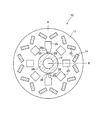
- the rotor 10 of the present embodiment has a core 11 fixed to a shaft 12 as shown in FIGS.
- FIG. 2 is a cross-sectional view taken along the line AA in FIG.
- the core 11 of the rotor 10 of this embodiment is formed of laminated steel plates, and permanent magnets 14 are embedded in various places.
- the rotor 10 is used for an inner rotor type motor of a permanent magnet embedded type (IPM type).
- a plurality of types of through holes 23, 24, 25, and 26 are formed in the core 11.
- through holes 23 provided on the outermost peripheral side penetrate the core 11 in the stacking direction, and permanent magnets 14 are embedded therein.
- the through holes 23 are arranged in a balanced manner in almost all directions. Note that the core 11 of this embodiment has 16 through holes 23 formed in total.
- a plurality of through holes 24 are arranged on the inner peripheral side of the core 11 from the through holes 23 as shown in FIG.
- the through hole 24 is for reducing the weight of the core 11, and its inside is a cavity.
- welding through holes 25 having slightly different shapes from the through holes 24 are formed at two positions in the vertical direction in the figure.
- a shaft through hole 26 is formed at the position of the rotation center of the core 11.
- the shaft through hole 26 is formed to have a diameter that allows the shaft to pass therethrough, and FIGS. 1 and 2 show a state in which the shaft 12 passes therethrough.
- the welding through hole 25 is formed to a position very close to the shaft through hole 26 as shown in FIG. That is, the wall surface 25 a on the shaft through hole 26 side of the welding through hole 25 is formed at a position adjacent to the wall surface of the shaft through hole 26.
- a bridge portion 28 is provided between the wall surface 25 a and the shaft through hole 26. In other words, the welding through hole 25 and the shaft through hole 26 are partitioned by the bridge portion 28.
- a welding mark 29 is formed on the bridge portion 28.
- the welding mark 29 penetrates the bridge portion 28 and extends from the wall surface 25 a to a part of the shaft 12. As shown in FIG. 2, the welding mark 29 is formed in a streak shape over the entire stacking direction of the cores 11. That is, it is formed over the entire core 11 along the axial direction of the shaft 12.
- the welding mark 29 is a mark that is welded by irradiating an electron beam from the welding through hole 25 toward the wall surface 25a.
- This weld mark 29 indicates that the bridge portion 28 and the surface portion of the shaft 12 are fused and integrated for all the steel plates of the core 11. At the same time, the steel plates constituting the core 11 are also fused and integrated with each other at the position of the weld mark 29. This prevents any rotation between the steel plates of the core 11, rotation of the core 11 around the shaft 12, and movement of the core 11 in the axial direction of the shaft 12. That is, the core 11 and the shaft 12 are securely fixed by the welding marks 29.
- the shaft 12 corresponds to a rotation transmission member.
- the wall surface of the shaft through hole 26 of the core 11 corresponds to the rotation transmission member mounting end surface, and the wall surface 25a of the welding through hole 25 corresponds to the welding end surface.
- the welding trace 29 has penetrated the bridge part 28, the shaft through-hole 26 and the wall surface 25a via the bridge part 28 exist in the adjacent position. According to this embodiment, in order to fix the core 11 and the shaft 12, there is no need to bring a plate member into contact with the end portion in the stacking direction or to form a keyway on the shaft.
- the welding through-hole 25 is two places here, as long as the core 11 and the shaft 12 can be fixed reliably, one place may be sufficient and it is good also as three or more places. Moreover, there is no restriction
- each yoke 41 is punched from the original plate as shown in FIG.
- the yokes 41 having substantially the same disk shape and the same shape are manufactured as many as the cores 11 as necessary.
- through holes 43, 44, 45, and 46 are simultaneously formed by punching at locations corresponding to the through holes 23, 24, 25, and 26 of the core 11, respectively.
- each yoke 41 is formed with a bridge 48 corresponding to the bridge portion 28 of the core 11 between the through hole 45 and the through hole 46.
- the necessary number of yokes 41 are stacked on the core 11.
- the positions of the through holes 43, 44, 45, 46 of each yoke 41 are aligned and stacked.
- the through holes 43 of the yokes 41 overlap to form the through holes 23 of the core 11.
- the through holes 44, 45, 46 of each yoke 41 overlap to form the through holes 24, 25, 26 of the core 11, respectively.
- a permanent magnet may be embedded in each through-hole 23 formed or may be embedded in a later step.
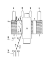
- the shaft 12 manufactured separately is passed through the portion (the shaft through hole 26) where the through holes 46 of the yokes 41 laminated in the (2) lamination step overlap. Then, the shaft 12 is inserted to an appropriate position.
- the electron beam 52 strikes the bridge 48 (A) of the yoke 41 at the end closest to the incident side (the left end in the figure). Positioning is in progress. Then, the electron beam 52 (A) is irradiated. As a result, the portion of the bridge 48 (A) that has been hit by the electron beam 52 (A) is melted. Furthermore, the periphery melts and the melting region extends to the shaft 12. As the melted portion hardens, the yoke 41 and the shaft 12 are fixed at this location.
- the electron gun 51 is moved along the axial direction of the shaft 12 from left to right in FIG.
- the incident direction of the electron beam 52 is set to a plane formed by the radial direction of the core 11 and the axial direction of the shaft 12 at the location of the through hole 25 for welding. Thereby, it is possible to prevent the electron beam 52 from hitting any place other than the bridge 48.
- the bridges 48 of all the yokes 41 are welded to the outer peripheral surface of the shaft 12. Welding is complete. Further, if the permanent magnet is not embedded in the previous (2) lamination step, it is performed after this. Thus, the rotor 10 is manufactured.
- the jig 61 may be disposed at the right end of the core 11 in the drawing, and the leftmost yoke 41 in the drawing may be pushed from the left to the right in the drawing as indicated by a white arrow in the drawing. Further, in this figure, a jig 63 is applied to the shaft 12 so as not to be displaced. Alternatively, the entire core 11 may be sandwiched in the stacking direction and held so as not to be displaced.
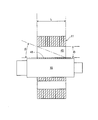
- a predetermined space is required above the bridge 48 in the drawing so that the electron beam 52 can be applied to the side farthest from the electron gun 51 (the right end in FIG. 4). It is.
- the incident angle ⁇ with respect to the weld surface is required to be at least 10 ° or more as shown in FIG. Therefore, the space required above the bridge 48, that is, the radial size D of the core 11 of the through hole 45 is within the range represented by the following formula using the laminated thickness L of the core 11. Is desirable. D ⁇ L ⁇ tan10 °
- the above incident angle ⁇ is more preferably 15 ° or more.
- the radial size D of the core 11 of the through hole 45 is a range represented by the following expression. D ⁇ L ⁇ tan15 °
- the width W of the through hole 45 (the size of the core 11 in the circumferential direction, see FIG. 3) needs to be at least equal to or larger than the beam diameter of the electron beam 52.
- the range through which the electron beam 52 passes through the through hole 45 for example, it is preferably 2 mm or more.
- the range in which the electron beam 52 passes is within the distance corresponding to the minimum value of D obtained from one of the above-mentioned formulas from the side of the bridge 48 in the through hole 45.
- the width V of the bridge 48 (distance between the through hole 45 and the through hole 46, see FIG. 3) is the width of the bridge portion 28 in the core 11. That is, it is sufficient if the melting range by the electron beam 52 extends to the shaft 12. That is, it is appropriate to be smaller than the depth to be welded, for example, within a range of 1 to 5 mm. Therefore, the fact that the end face for welding and the end face for attaching the rotation transmission member are adjacent means that the distance between the holes is smaller than the melting depth when welding.
- the direction of movement of the electron gun 51 may be reversed ((B) ⁇ (A)).
- the welding can be appropriately performed by changing the emission direction of the electron beam 52.
- the electron gun 51 may be fixed and the core 11 that is the object may be moved.
- welding is performed on the entire range from one side thereof, but half of each may be performed from both sides. In that case, L may be replaced with L / 2 in the above formula D.
- laser welding can be used instead of electron beam welding.
- (4) fillet welding was used instead of the above lap welding as the welding method in the welding process. That is, the bridge 48 between the welding through hole 25 and the shaft through hole 26 is eliminated, and a part of the through hole through which the shaft 12 passes is expanded in the radial direction of the core. From the space between the expanded through hole (through hole 64 in FIG. 6, through hole 74 in FIG. 8) and the shaft 12, electrons are transferred from the wall surface of the through hole to the shaft 12. The shaft 12 and the core were welded by irradiating the beam. That is, the through hole for welding and the through hole for shaft are made into one continuous through hole 64, 74.
- the contact portion with the shaft 12 corresponds to the rotation transmitting member mounting end surface
- the wall surface of the through holes 64 and 74 is along the contact portion with the shaft 12.
- the part within the range corresponds to the end face for welding. These are positions that can be melted together by irradiating the boundary with an electron beam. Therefore, the fact that the end face for welding and the end face for attaching the rotation transmitting member are adjacent means that, when the hole is continuous, it is within the range where melting by the irradiation of the electron beam reaches.
- a through hole for embedding a permanent magnet (corresponding to the through hole 23 in FIG. 1) is omitted. Further, although a through hole (corresponding to the through hole 24 in FIG. 1) may be further provided for weight reduction, this is also omitted.
- the rotor 61 shown in FIG. 6 has a core 63 and a shaft 12.
- the core 63 is formed with an equilateral triangular through hole 64 having a size in which the shaft 12 is inscribed.
- the rotor 61 is the shaft 61 inserted and fixed in the through hole 64.
- the core 63 is formed by stacking yokes 65 formed in the shape shown in FIG. When the yoke 65 is laminated and the shaft 12 is inserted into the through hole 64, the yoke 65 is inserted as shown by a broken line in FIG.
- the through hole 64 corresponds to the through hole 46 and the through hole 45 in FIG. There is no portion corresponding to the bridge 48.
- the three locations where the yoke 65 and the shaft 12 are in contact correspond to the rotation transmission member mounting end surface.
- a portion slightly away from the shaft 12 corresponds to the end surface for welding within a range in which the rotation transmitting member can be fused together by welding from both ends of the rotation transmission member mounting end surface. Therefore, also in this embodiment, these end faces are adjacent positions.
- the through hole 64 and the outer peripheral surface of the shaft 12 are in contact with each other at three locations, and at the three apex locations of the through hole 64, a gap 67 is provided between the yoke 65 and the shaft 12. Remains. Therefore, the gap 67 can be used to irradiate the electron beam toward the boundary where the through hole 64 and the outer peripheral surface of the shaft 12 are in contact, as indicated by an arrow Y in the drawing. Thereby, the core 63 and the shaft 12 can be welded at the boundary.
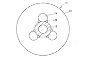
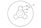
- a rotor 71 as shown in FIG. 8 may be used.
- the core 73 of the rotor 71 has a through hole 74 and is formed by stacking yokes 75 shown in FIG.
- a hump-like extended portion 74b is formed at three locations.
- the shaft 12 is inserted into the through hole 74, it is inserted as shown by a broken line in FIG.
- the outer peripheral shape portion 74a corresponds to the rotation transmitting member attachment end surface
- the wall surface of the extended portion 74b within the range along the outer peripheral shape portion 74a corresponds to the end surface for welding. These are arranged adjacent to each other in the aforementioned sense.
- the welding through hole 25 for welding is formed adjacent to the shaft through hole 26 through which the shaft 12 passes through a part of the core 11. Since the welding mark 29 extending from the welding through hole 25 to the shaft 12 is formed, all the yokes 41 and the shaft 12 constituting the core 11 are securely fixed. Further, since each yoke 41 is fixed in all directions by welding, a fixing process is not necessary. Further, a plate material sandwiching both end portions of the core 11 in the stacking direction, a space for caulking, and the like that are conventionally used are unnecessary. Therefore, it is easy to reduce the size and weight of the rotating electrical machine, and the rotor can be manufactured with a small number of processes.
- the outer shape of the shaft is not limited to a cylindrical shape, but may be a polygonal column shape, a spline, a serration, or the like.
- the shaft and the core may be further fitted with a key and a key groove.
- one side of the core in the stacking direction can be received by a flange portion provided on the shaft.
- the shaft is not limited to a single shaft, but may be a divided type.
- the steel plates in the core may be fixed in advance by caulking, welding, bonding, resin molding, or the like.
- a core that is divided into a plurality of parts in the circumferential direction may be used as the core.
- the present invention is not limited to the permanent magnet embedded IPM type motor, but can also be applied to an SPM type motor in which a magnet is arranged on the rotor surface. Further, the present invention can be applied not only to the inner rotor type but also to the outer rotor type.
Abstract
Description
このようになっていれば,溶接用貫通穴を利用して,溶接用端面からシャフト用貫通穴に向かって溶接することにより,それらの間を溶融させてシャフトまでに及ぶ溶接を行うことができる。
D ≧ L×tan10°
を満たしていることが望ましい。
このようになっていれば,コアの積層方向の一方の端部から,他方の端部まで届くようにビームを照射することができる。
このようになっていれば,貫通穴を利用して,その壁面とシャフトとの境目の箇所に向かって溶接することにより,その両方を溶融させてシャフトまでに及ぶ溶接を行うことができる。
この態様によれば,鋼板を積層して,回転伝達部材取付端面と溶接用端面とが形成されたコアとすることができる。さらに,そのコアに回転伝達部材を取り付け,溶接用端面から溶接すれば,溶接痕が形成されたロータを容易に製造することができる。
このようにすれば,積層方向の全体にわたって溶接することは容易である。
(1)打ち抜き工程
(2)積層工程
(3)シャフト貫通工程
(4)溶接工程
D ≧ L × tan10°
D ≧ L × tan15°
さらに,貫通穴45の幅W(コア11の周方向への大きさ,図3参照)は,少なくとも電子ビーム52のビーム径以上であることが必要である。貫通穴45のうち電子ビーム52が通過する範囲内では,例えば2mm以上とすることが好ましい。電子ビーム52が通過する範囲内とは,貫通穴45のうち,ブリッジ48の側の辺から,上記のいずれかの式により求められるDの最小値に相当する距離の範囲内である。
例えば,シャフトの外形は円筒状に限らず,多角柱形状やスプライン,セレーション等でもよい。また,シャフトとコアとの間にさらにキーとキー溝とによる嵌め合いをも有していてもよい。また,コアの積層方向の片側をシャフトに設けたフランジ部で受けるようにすることもできる。また,シャフトとして,一体のものに限らず,分割タイプのものであってもよい。
11,63,73 コア
12 シャフト
25 溶接用貫通穴
26 シャフト用貫通穴
29 溶接痕
64,74 貫通穴
Claims (6)
- 積層鋼板からなり,その積層方向全体にわたる回転伝達部材取付端面が形成されたコアと,前記コアの前記回転伝達部材取付端面に取り付けられた回転伝達部材とを有するロータにおいて,
前記コアには,その積層方向全体にわたる溶接用端面が,前記回転伝達部材取付端面と隣接する位置に形成されており,
前記溶接用端面に,前記回転伝達部材に及ぶ溶接痕が,前記コアの積層方向の全体にわたって形成されていることを特徴とするロータ。 - 請求項1に記載のロータにおいて,
前記回転伝達部材が,前記ロータの回転中心を貫通して配置されているシャフトであり,
前記コアには,前記シャフトを貫通させるためのシャフト用貫通穴と,前記シャフト用貫通穴の周囲に設けられた溶接用貫通穴とが,ともにその積層方向の全体にわたって形成されており,
前記回転伝達部材取付端面は,前記シャフト用貫通穴の壁面であり,
前記溶接用端面は,前記溶接用貫通穴のうち前記シャフト用貫通穴の側の壁面であることを特徴とするロータ。 - 請求項2に記載のロータにおいて,
前記溶接用貫通穴の前記コアの周方向における大きさは2mm以上であり,かつ,前記溶接用貫通穴の前記コアの径方向における大きさDは,前記コアの積層厚をLとして,
D ≧ L×tan10°
を満たしていることを特徴とするロータ。 - 請求項1に記載のロータにおいて,
前記回転伝達部材が,前記ロータの回転中心を貫通して配置されているシャフトであり,
前記コアには,前記シャフトを貫通させるための貫通穴が,その積層方向の全体にわたって形成されており,
前記回転伝達部材取付端面は,前記貫通穴の壁面の一部であり,
前記溶接用端面が,前記貫通穴の壁面のうち前記回転伝達部材取付端面に沿った部分であることを特徴とするロータ。 - 積層鋼板からなり,その積層方向全体にわたる回転伝達部材取付端面が形成されたコアと,前記コアの前記回転伝達部材取付端面に取り付けられた回転伝達部材とを有するロータの製造方法において,
前記回転伝達部材取付端面と,前記回転伝達部材取付端面と隣接する位置に形成された溶接用端面とをいずれも有する複数枚の鋼板を積層して前記コアとし,前記回転伝達部材取付端面に前記回転伝達部材を取り付ける工程と,
前記溶接用端面から前記回転伝達部材までに及ぶ範囲を,前記コアの積層方向の全体にわたってビームを照射することによって溶接する工程とを有することを特徴とするロータの製造方法。 - 請求項6に記載のロータの製造方法において,
前記溶接する工程は,ビームの照射箇所を前記コアの積層方向に沿って移動させることにより行うことを特徴とするロータの製造方法。
Priority Applications (6)
| Application Number | Priority Date | Filing Date | Title |
|---|---|---|---|
| KR1020117017167A KR101224700B1 (ko) | 2009-10-09 | 2009-10-09 | 로터 및 그 제조 방법 |
| PCT/JP2009/067633 WO2011042984A1 (ja) | 2009-10-09 | 2009-10-09 | ロータおよびその製造方法 |
| EP09850255.2A EP2487777A4 (en) | 2009-10-09 | 2009-10-09 | ROTOR AND METHOD FOR ITS MANUFACTURE |
| CN200980155423.8A CN102292898B (zh) | 2009-10-09 | 2009-10-09 | 转子及其制造方法 |
| JP2011506515A JP5126414B2 (ja) | 2009-10-09 | 2009-10-09 | ロータおよびその製造方法 |
| US13/145,864 US8669686B2 (en) | 2009-10-09 | 2009-10-09 | Rotor and method of manufacturing the rotor |
Applications Claiming Priority (1)
| Application Number | Priority Date | Filing Date | Title |
|---|---|---|---|
| PCT/JP2009/067633 WO2011042984A1 (ja) | 2009-10-09 | 2009-10-09 | ロータおよびその製造方法 |
Publications (1)
| Publication Number | Publication Date |
|---|---|
| WO2011042984A1 true WO2011042984A1 (ja) | 2011-04-14 |
Family
ID=43856476
Family Applications (1)
| Application Number | Title | Priority Date | Filing Date |
|---|---|---|---|
| PCT/JP2009/067633 WO2011042984A1 (ja) | 2009-10-09 | 2009-10-09 | ロータおよびその製造方法 |
Country Status (6)
| Country | Link |
|---|---|
| US (1) | US8669686B2 (ja) |
| EP (1) | EP2487777A4 (ja) |
| JP (1) | JP5126414B2 (ja) |
| KR (1) | KR101224700B1 (ja) |
| CN (1) | CN102292898B (ja) |
| WO (1) | WO2011042984A1 (ja) |
Cited By (8)
| Publication number | Priority date | Publication date | Assignee | Title |
|---|---|---|---|---|
| JP2014050218A (ja) * | 2012-08-31 | 2014-03-17 | Denso Corp | マルチギャップ型回転電機 |
| JP2014050210A (ja) * | 2012-08-31 | 2014-03-17 | Hitachi Automotive Systems Ltd | 回転電機 |
| US8698371B2 (en) | 2010-03-15 | 2014-04-15 | Toyota Jidosha Kabushiki Kaisha | Rotor and method of manufacturing the rotor |
| GB2506932A (en) * | 2012-10-15 | 2014-04-16 | Nissan Motor Mfg Uk Ltd | Laminated rotor assembly |
| JP2018133906A (ja) * | 2017-02-15 | 2018-08-23 | トヨタ自動車株式会社 | 回転電機ロータ |
| JP2019062644A (ja) * | 2017-09-26 | 2019-04-18 | アイシン・エィ・ダブリュ株式会社 | 回転電機 |
| WO2019088156A1 (ja) * | 2017-10-31 | 2019-05-09 | 日本電産株式会社 | ロータおよびモータ |
| WO2020230507A1 (ja) * | 2019-05-15 | 2020-11-19 | パナソニックIpマネジメント株式会社 | ロータ及びそれを備えたモータ |
Families Citing this family (3)
| Publication number | Priority date | Publication date | Assignee | Title |
|---|---|---|---|---|
| US20140097711A1 (en) * | 2012-10-05 | 2014-04-10 | Larry Kubes | One piece rotor hub/shaft for an electric machine and method |
| JP6495747B2 (ja) * | 2015-06-05 | 2019-04-03 | 株式会社三井ハイテック | 積層鉄心の検査装置及び積層鉄心の検査方法 |
| DE202017007061U1 (de) * | 2017-03-08 | 2019-05-03 | Nidec Corporation | Gehäuse für einen Elektromotor |
Citations (8)
| Publication number | Priority date | Publication date | Assignee | Title |
|---|---|---|---|---|
| JPS5475004A (en) * | 1977-11-28 | 1979-06-15 | Hitachi Ltd | Method for manufacturing rotor |
| JPS5734747A (en) * | 1980-08-08 | 1982-02-25 | Toshiba Corp | Rotary electric machine |
| JPS5911745A (ja) * | 1982-07-09 | 1984-01-21 | Toshiba Corp | 回転電機 |
| JPH05199695A (ja) * | 1992-01-20 | 1993-08-06 | Toshiba Corp | 回転電機の固定子枠 |
| JP2000116046A (ja) * | 1998-10-02 | 2000-04-21 | Miyachi Technos Corp | モータ回転子及びその組立方法 |
| JP2002136067A (ja) | 2000-10-27 | 2002-05-10 | Nissan Motor Co Ltd | 磁石モータ用ロータ |
| JP2006254662A (ja) * | 2005-03-14 | 2006-09-21 | Mitsubishi Electric Corp | 回転子およびモータ |
| JP2007124752A (ja) | 2005-10-26 | 2007-05-17 | Toyota Motor Corp | ロータシャフトおよびロータシャフトの製造方法 |
Family Cites Families (13)
| Publication number | Priority date | Publication date | Assignee | Title |
|---|---|---|---|---|
| JPS6046620B2 (ja) * | 1980-10-24 | 1985-10-17 | 株式会社デンソー | 回転電機用鉄心 |
| FI91818C (fi) * | 1992-08-21 | 1994-08-10 | Abb Stroemberg Drives Oy | Sähkökoneen roottorirakenne |
| JPH09168258A (ja) | 1995-12-14 | 1997-06-24 | Matsushita Electric Ind Co Ltd | アマチュアコアの組立方法 |
| JPH10164802A (ja) | 1996-11-27 | 1998-06-19 | Toshiba Corp | 鉄心の製造方法 |
| JP3555377B2 (ja) | 1997-03-12 | 2004-08-18 | 三菱電機株式会社 | ロータ及びロータの製造方法 |
| JP2001298903A (ja) * | 2000-04-10 | 2001-10-26 | Moric Co Ltd | ブラシレスdcモータ |
| JP4590714B2 (ja) * | 2000-10-23 | 2010-12-01 | パナソニック株式会社 | ブラシレスモータ及びその製造方法 |
| GB0109847D0 (en) * | 2001-04-21 | 2001-06-13 | Johnson Electric Sa | Motor |
| JP3724447B2 (ja) * | 2002-04-01 | 2005-12-07 | 日産自動車株式会社 | ロータ構体及びその製造方法 |
| JP3790824B2 (ja) * | 2004-01-29 | 2006-06-28 | 三菱電機株式会社 | ロータ及びその製造方法 |
| TWI382634B (zh) * | 2004-12-15 | 2013-01-11 | Panasonic Corp | 具雙重絕緣構造之馬達及搭載有該馬達之電子機器 |
| JP5231790B2 (ja) * | 2007-11-20 | 2013-07-10 | 日本電産テクノモータ株式会社 | モータ回転子及びモータ |
| DE102007055542A1 (de) * | 2007-11-21 | 2009-06-04 | Bühler Motor GmbH | Rotor eines Elektromotors |
-
2009
- 2009-10-09 US US13/145,864 patent/US8669686B2/en not_active Expired - Fee Related
- 2009-10-09 WO PCT/JP2009/067633 patent/WO2011042984A1/ja active Application Filing
- 2009-10-09 EP EP09850255.2A patent/EP2487777A4/en not_active Withdrawn
- 2009-10-09 CN CN200980155423.8A patent/CN102292898B/zh not_active Expired - Fee Related
- 2009-10-09 KR KR1020117017167A patent/KR101224700B1/ko not_active IP Right Cessation
- 2009-10-09 JP JP2011506515A patent/JP5126414B2/ja not_active Expired - Fee Related
Patent Citations (8)
| Publication number | Priority date | Publication date | Assignee | Title |
|---|---|---|---|---|
| JPS5475004A (en) * | 1977-11-28 | 1979-06-15 | Hitachi Ltd | Method for manufacturing rotor |
| JPS5734747A (en) * | 1980-08-08 | 1982-02-25 | Toshiba Corp | Rotary electric machine |
| JPS5911745A (ja) * | 1982-07-09 | 1984-01-21 | Toshiba Corp | 回転電機 |
| JPH05199695A (ja) * | 1992-01-20 | 1993-08-06 | Toshiba Corp | 回転電機の固定子枠 |
| JP2000116046A (ja) * | 1998-10-02 | 2000-04-21 | Miyachi Technos Corp | モータ回転子及びその組立方法 |
| JP2002136067A (ja) | 2000-10-27 | 2002-05-10 | Nissan Motor Co Ltd | 磁石モータ用ロータ |
| JP2006254662A (ja) * | 2005-03-14 | 2006-09-21 | Mitsubishi Electric Corp | 回転子およびモータ |
| JP2007124752A (ja) | 2005-10-26 | 2007-05-17 | Toyota Motor Corp | ロータシャフトおよびロータシャフトの製造方法 |
Non-Patent Citations (1)
| Title |
|---|
| See also references of EP2487777A4 * |
Cited By (12)
| Publication number | Priority date | Publication date | Assignee | Title |
|---|---|---|---|---|
| US8698371B2 (en) | 2010-03-15 | 2014-04-15 | Toyota Jidosha Kabushiki Kaisha | Rotor and method of manufacturing the rotor |
| JP2014050218A (ja) * | 2012-08-31 | 2014-03-17 | Denso Corp | マルチギャップ型回転電機 |
| JP2014050210A (ja) * | 2012-08-31 | 2014-03-17 | Hitachi Automotive Systems Ltd | 回転電機 |
| GB2506932A (en) * | 2012-10-15 | 2014-04-16 | Nissan Motor Mfg Uk Ltd | Laminated rotor assembly |
| JP2018133906A (ja) * | 2017-02-15 | 2018-08-23 | トヨタ自動車株式会社 | 回転電機ロータ |
| JP2019062644A (ja) * | 2017-09-26 | 2019-04-18 | アイシン・エィ・ダブリュ株式会社 | 回転電機 |
| WO2019088156A1 (ja) * | 2017-10-31 | 2019-05-09 | 日本電産株式会社 | ロータおよびモータ |
| JPWO2019088156A1 (ja) * | 2017-10-31 | 2020-11-12 | 日本電産株式会社 | ロータおよびモータ |
| WO2020230507A1 (ja) * | 2019-05-15 | 2020-11-19 | パナソニックIpマネジメント株式会社 | ロータ及びそれを備えたモータ |
| JP2020188611A (ja) * | 2019-05-15 | 2020-11-19 | パナソニックIpマネジメント株式会社 | ロータ及びそれを備えたモータ |
| CN113812064A (zh) * | 2019-05-15 | 2021-12-17 | 松下知识产权经营株式会社 | 转子和具有该转子的电动机 |
| JP7266180B2 (ja) | 2019-05-15 | 2023-04-28 | パナソニックIpマネジメント株式会社 | ロータ及びそれを備えたモータ |
Also Published As
| Publication number | Publication date |
|---|---|
| JP5126414B2 (ja) | 2013-01-23 |
| US20120019097A1 (en) | 2012-01-26 |
| CN102292898B (zh) | 2014-07-02 |
| US8669686B2 (en) | 2014-03-11 |
| CN102292898A (zh) | 2011-12-21 |
| EP2487777A1 (en) | 2012-08-15 |
| KR101224700B1 (ko) | 2013-01-21 |
| JPWO2011042984A1 (ja) | 2013-02-28 |
| KR20110106897A (ko) | 2011-09-29 |
| EP2487777A4 (en) | 2016-01-06 |
Similar Documents
| Publication | Publication Date | Title |
|---|---|---|
| JP5126414B2 (ja) | ロータおよびその製造方法 | |
| JP5299514B2 (ja) | ロータおよびその製造方法 | |
| JP5278551B2 (ja) | 回転電機用ロータコアおよびその製造方法 | |
| WO2017090571A1 (ja) | モータおよびモータの製造方法 | |
| CN110431735B (zh) | 芯制造方法和芯 | |
| JP2007151360A (ja) | 積層体の製造方法 | |
| JP2012205444A (ja) | ステータコアとその製造方法およびモータ | |
| CN110268608B (zh) | 旋转电机用部件的制造方法 | |
| CN112737166B (zh) | 旋转电机和旋转电机的制造方法 | |
| JP6293382B1 (ja) | 固定子コア片及び回転電機 | |
| EP2831979A1 (en) | Rotor including segmented yoke | |
| JP2010130884A (ja) | 回転電機及び回転電機の製造方法 | |
| CN111557071B (zh) | 转子的制造方法 | |
| JP7024856B2 (ja) | 回転電機用ロータ | |
| JP6696455B2 (ja) | 回転電機ロータ | |
| JP2018117440A (ja) | 回転電機 | |
| JP2021027736A (ja) | 積層構造体の製造方法及び積層構造体 |
Legal Events
| Date | Code | Title | Description |
|---|---|---|---|
| WWE | Wipo information: entry into national phase |
Ref document number: 200980155423.8 Country of ref document: CN |
|
| WWE | Wipo information: entry into national phase |
Ref document number: 2011506515 Country of ref document: JP |
|
| 121 | Ep: the epo has been informed by wipo that ep was designated in this application |
Ref document number: 09850255 Country of ref document: EP Kind code of ref document: A1 |
|
| WWE | Wipo information: entry into national phase |
Ref document number: 2009850255 Country of ref document: EP |
|
| ENP | Entry into the national phase |
Ref document number: 20117017167 Country of ref document: KR Kind code of ref document: A |
|
| WWE | Wipo information: entry into national phase |
Ref document number: 13145864 Country of ref document: US |
|
| NENP | Non-entry into the national phase |
Ref country code: DE |