WO2011040209A1 - 減圧弁の弁軸連結構造および方法 - Google Patents
減圧弁の弁軸連結構造および方法 Download PDFInfo
- Publication number
- WO2011040209A1 WO2011040209A1 PCT/JP2010/065607 JP2010065607W WO2011040209A1 WO 2011040209 A1 WO2011040209 A1 WO 2011040209A1 JP 2010065607 W JP2010065607 W JP 2010065607W WO 2011040209 A1 WO2011040209 A1 WO 2011040209A1
- Authority
- WO
- WIPO (PCT)
- Prior art keywords
- diaphragm
- valve
- shaft
- passage
- gas passage
- Prior art date
- Legal status (The legal status is an assumption and is not a legal conclusion. Google has not performed a legal analysis and makes no representation as to the accuracy of the status listed.)
- Ceased
Links
Images




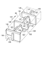

Classifications
-
- F—MECHANICAL ENGINEERING; LIGHTING; HEATING; WEAPONS; BLASTING
- F02—COMBUSTION ENGINES; HOT-GAS OR COMBUSTION-PRODUCT ENGINE PLANTS
- F02M—SUPPLYING COMBUSTION ENGINES IN GENERAL WITH COMBUSTIBLE MIXTURES OR CONSTITUENTS THEREOF
- F02M21/00—Apparatus for supplying engines with non-liquid fuels, e.g. gaseous fuels stored in liquid form
- F02M21/02—Apparatus for supplying engines with non-liquid fuels, e.g. gaseous fuels stored in liquid form for gaseous fuels
- F02M21/0218—Details on the gaseous fuel supply system, e.g. tanks, valves, pipes, pumps, rails, injectors or mixers
- F02M21/023—Valves; Pressure or flow regulators in the fuel supply or return system
- F02M21/0239—Pressure or flow regulators therefor
-
- F—MECHANICAL ENGINEERING; LIGHTING; HEATING; WEAPONS; BLASTING
- F16—ENGINEERING ELEMENTS AND UNITS; GENERAL MEASURES FOR PRODUCING AND MAINTAINING EFFECTIVE FUNCTIONING OF MACHINES OR INSTALLATIONS; THERMAL INSULATION IN GENERAL
- F16K—VALVES; TAPS; COCKS; ACTUATING-FLOATS; DEVICES FOR VENTING OR AERATING
- F16K7/00—Diaphragm valves or cut-off apparatus, e.g. with a member deformed, but not moved bodily, to close the passage ; Pinch valves
- F16K7/12—Diaphragm valves or cut-off apparatus, e.g. with a member deformed, but not moved bodily, to close the passage ; Pinch valves with flat, dished, or bowl-shaped diaphragm
-
- F—MECHANICAL ENGINEERING; LIGHTING; HEATING; WEAPONS; BLASTING
- F02—COMBUSTION ENGINES; HOT-GAS OR COMBUSTION-PRODUCT ENGINE PLANTS
- F02M—SUPPLYING COMBUSTION ENGINES IN GENERAL WITH COMBUSTIBLE MIXTURES OR CONSTITUENTS THEREOF
- F02M21/00—Apparatus for supplying engines with non-liquid fuels, e.g. gaseous fuels stored in liquid form
- F02M21/02—Apparatus for supplying engines with non-liquid fuels, e.g. gaseous fuels stored in liquid form for gaseous fuels
- F02M21/0218—Details on the gaseous fuel supply system, e.g. tanks, valves, pipes, pumps, rails, injectors or mixers
- F02M21/023—Valves; Pressure or flow regulators in the fuel supply or return system
- F02M21/0233—Details of actuators therefor
-
- F—MECHANICAL ENGINEERING; LIGHTING; HEATING; WEAPONS; BLASTING
- F02—COMBUSTION ENGINES; HOT-GAS OR COMBUSTION-PRODUCT ENGINE PLANTS
- F02M—SUPPLYING COMBUSTION ENGINES IN GENERAL WITH COMBUSTIBLE MIXTURES OR CONSTITUENTS THEREOF
- F02M21/00—Apparatus for supplying engines with non-liquid fuels, e.g. gaseous fuels stored in liquid form
- F02M21/02—Apparatus for supplying engines with non-liquid fuels, e.g. gaseous fuels stored in liquid form for gaseous fuels
- F02M21/06—Apparatus for de-liquefying, e.g. by heating
-
- F—MECHANICAL ENGINEERING; LIGHTING; HEATING; WEAPONS; BLASTING
- F16—ENGINEERING ELEMENTS AND UNITS; GENERAL MEASURES FOR PRODUCING AND MAINTAINING EFFECTIVE FUNCTIONING OF MACHINES OR INSTALLATIONS; THERMAL INSULATION IN GENERAL
- F16K—VALVES; TAPS; COCKS; ACTUATING-FLOATS; DEVICES FOR VENTING OR AERATING
- F16K17/00—Safety valves; Equalising valves, e.g. pressure relief valves
- F16K17/02—Safety valves; Equalising valves, e.g. pressure relief valves opening on surplus pressure on one side; closing on insufficient pressure on one side
- F16K17/04—Safety valves; Equalising valves, e.g. pressure relief valves opening on surplus pressure on one side; closing on insufficient pressure on one side spring-loaded
-
- G—PHYSICS
- G05—CONTROLLING; REGULATING
- G05D—SYSTEMS FOR CONTROLLING OR REGULATING NON-ELECTRIC VARIABLES
- G05D16/00—Control of fluid pressure
- G05D16/04—Control of fluid pressure without auxiliary power
- G05D16/06—Control of fluid pressure without auxiliary power the sensing element being a flexible membrane, yielding to pressure, e.g. diaphragm, bellows, capsule
-
- G—PHYSICS
- G05—CONTROLLING; REGULATING
- G05D—SYSTEMS FOR CONTROLLING OR REGULATING NON-ELECTRIC VARIABLES
- G05D16/00—Control of fluid pressure
- G05D16/04—Control of fluid pressure without auxiliary power
- G05D16/06—Control of fluid pressure without auxiliary power the sensing element being a flexible membrane, yielding to pressure, e.g. diaphragm, bellows, capsule
- G05D16/063—Control of fluid pressure without auxiliary power the sensing element being a flexible membrane, yielding to pressure, e.g. diaphragm, bellows, capsule the sensing element being a membrane
- G05D16/0644—Control of fluid pressure without auxiliary power the sensing element being a flexible membrane, yielding to pressure, e.g. diaphragm, bellows, capsule the sensing element being a membrane the membrane acting directly on the obturator
- G05D16/0655—Control of fluid pressure without auxiliary power the sensing element being a flexible membrane, yielding to pressure, e.g. diaphragm, bellows, capsule the sensing element being a membrane the membrane acting directly on the obturator using one spring-loaded membrane
-
- F—MECHANICAL ENGINEERING; LIGHTING; HEATING; WEAPONS; BLASTING
- F02—COMBUSTION ENGINES; HOT-GAS OR COMBUSTION-PRODUCT ENGINE PLANTS
- F02M—SUPPLYING COMBUSTION ENGINES IN GENERAL WITH COMBUSTIBLE MIXTURES OR CONSTITUENTS THEREOF
- F02M21/00—Apparatus for supplying engines with non-liquid fuels, e.g. gaseous fuels stored in liquid form
- F02M21/02—Apparatus for supplying engines with non-liquid fuels, e.g. gaseous fuels stored in liquid form for gaseous fuels
- F02M21/0203—Apparatus for supplying engines with non-liquid fuels, e.g. gaseous fuels stored in liquid form for gaseous fuels characterised by the type of gaseous fuel
- F02M21/0209—Hydrocarbon fuels, e.g. methane or acetylene
- F02M21/0212—Hydrocarbon fuels, e.g. methane or acetylene comprising at least 3 C-Atoms, e.g. liquefied petroleum gas [LPG], propane or butane
-
- F—MECHANICAL ENGINEERING; LIGHTING; HEATING; WEAPONS; BLASTING
- F16—ENGINEERING ELEMENTS AND UNITS; GENERAL MEASURES FOR PRODUCING AND MAINTAINING EFFECTIVE FUNCTIONING OF MACHINES OR INSTALLATIONS; THERMAL INSULATION IN GENERAL
- F16K—VALVES; TAPS; COCKS; ACTUATING-FLOATS; DEVICES FOR VENTING OR AERATING
- F16K31/00—Actuating devices; Operating means; Releasing devices
- F16K31/12—Actuating devices; Operating means; Releasing devices actuated by fluid
- F16K31/126—Actuating devices; Operating means; Releasing devices actuated by fluid the fluid acting on a diaphragm, bellows, or the like
-
- Y—GENERAL TAGGING OF NEW TECHNOLOGICAL DEVELOPMENTS; GENERAL TAGGING OF CROSS-SECTIONAL TECHNOLOGIES SPANNING OVER SEVERAL SECTIONS OF THE IPC; TECHNICAL SUBJECTS COVERED BY FORMER USPC CROSS-REFERENCE ART COLLECTIONS [XRACs] AND DIGESTS
- Y02—TECHNOLOGIES OR APPLICATIONS FOR MITIGATION OR ADAPTATION AGAINST CLIMATE CHANGE
- Y02T—CLIMATE CHANGE MITIGATION TECHNOLOGIES RELATED TO TRANSPORTATION
- Y02T10/00—Road transport of goods or passengers
- Y02T10/10—Internal combustion engine [ICE] based vehicles
- Y02T10/30—Use of alternative fuels, e.g. biofuels
-
- Y—GENERAL TAGGING OF NEW TECHNOLOGICAL DEVELOPMENTS; GENERAL TAGGING OF CROSS-SECTIONAL TECHNOLOGIES SPANNING OVER SEVERAL SECTIONS OF THE IPC; TECHNICAL SUBJECTS COVERED BY FORMER USPC CROSS-REFERENCE ART COLLECTIONS [XRACs] AND DIGESTS
- Y10—TECHNICAL SUBJECTS COVERED BY FORMER USPC
- Y10T—TECHNICAL SUBJECTS COVERED BY FORMER US CLASSIFICATION
- Y10T137/00—Fluid handling
- Y10T137/0318—Processes
- Y10T137/0402—Cleaning, repairing, or assembling
- Y10T137/0441—Repairing, securing, replacing, or servicing pipe joint, valve, or tank
- Y10T137/0486—Specific valve or valve element mounting or repairing
-
- Y—GENERAL TAGGING OF NEW TECHNOLOGICAL DEVELOPMENTS; GENERAL TAGGING OF CROSS-SECTIONAL TECHNOLOGIES SPANNING OVER SEVERAL SECTIONS OF THE IPC; TECHNICAL SUBJECTS COVERED BY FORMER USPC CROSS-REFERENCE ART COLLECTIONS [XRACs] AND DIGESTS
- Y10—TECHNICAL SUBJECTS COVERED BY FORMER USPC
- Y10T—TECHNICAL SUBJECTS COVERED BY FORMER US CLASSIFICATION
- Y10T137/00—Fluid handling
- Y10T137/598—With repair, tapping, assembly, or disassembly means
- Y10T137/599—Pressure regulating type valve
- Y10T137/5994—Diaphragm type
-
- Y—GENERAL TAGGING OF NEW TECHNOLOGICAL DEVELOPMENTS; GENERAL TAGGING OF CROSS-SECTIONAL TECHNOLOGIES SPANNING OVER SEVERAL SECTIONS OF THE IPC; TECHNICAL SUBJECTS COVERED BY FORMER USPC CROSS-REFERENCE ART COLLECTIONS [XRACs] AND DIGESTS
- Y10—TECHNICAL SUBJECTS COVERED BY FORMER USPC
- Y10T—TECHNICAL SUBJECTS COVERED BY FORMER US CLASSIFICATION
- Y10T29/00—Metal working
- Y10T29/49—Method of mechanical manufacture
- Y10T29/494—Fluidic or fluid actuated device making
Definitions
- the present invention provides an improved valve shaft coupling structure and method for a pressure reducing valve for coupling a valve shaft coaxially coupled to a valve body of a valve mechanism housed in a body to a diaphragm rod coupled to a central portion of the diaphragm.
- a pressure reducing valve for coupling a valve shaft coaxially coupled to a valve body of a valve mechanism housed in a body to a diaphragm rod coupled to a central portion of the diaphragm.
- an O-ring, a first retainer, a diaphragm, a second retainer, and a washer are sequentially stacked on the valve shaft, and a nut is screwed into the center of the valve shaft and tightened to tighten the valve on the diaphragm.
- a connecting structure the tilt of the diaphragm with respect to the plane perpendicular to the valve axis direction and the deviation of the shaft center on the diaphragm side and the shaft center on the valve body side are not allowed, and the dimensions are strict. Management is required.
- the applicant of the present invention inserts a T-shaped engagement portion provided at one end of the valve shaft coupled to the valve body into the diaphragm rod and is fixed using a C-shaped engagement ring.
- An application has already been filed for a pressure reducing valve (Japanese Patent Application No. 2009-112808) in which a valve shaft is connected to a diaphragm rod so as to be loosely engaged with a T-shaped engagement groove provided in the insertion member. With such a connection structure, the valve shaft can be connected to the diaphragm rod with a simple and reliable structure that does not require strict dimensional control.
- the T-shaped engagement groove provided in the insertion member for engaging the T-shaped engagement portion at one end of the valve shaft is a part of the insertion member in a direction orthogonal to the central axis of the insertion member.
- a complicated shape having a concave portion that is asymmetric with respect to the central axis of the insertion member and cannot be formed by an inexpensive lathe process, resulting in high costs.
- the present invention has been made in view of such circumstances, and allows the manufacturing cost to be reduced while permitting the inclination of the diaphragm with respect to a plane perpendicular to the valve axis direction, and the deviation of the axis on the diaphragm side and the axis on the valve body side. It is an object of the present invention to provide a connection structure in which a valve shaft can be connected to a diaphragm rod with a simple structure as described above, and a connection method with improved assemblability using such a connection structure.
- the present invention provides a pressure reducing valve for connecting a valve shaft coaxially coupled to a valve body of a valve mechanism housed in a body to a diaphragm rod coupled to a central portion of the diaphragm.
- a pressure reducing valve for connecting a valve shaft coaxially coupled to a valve body of a valve mechanism housed in a body to a diaphragm rod coupled to a central portion of the diaphragm.
- an insertion recess opened to the valve mechanism side is provided coaxially with the diaphragm rod, and a reduced diameter shaft portion is provided at one end portion of the valve shaft, and the diameter is reduced on both axial sides of the reduced diameter shaft portion.
- a holding plate that has an engagement recess that opens in a lateral direction and has a substantially U-shaped cross section causes the one end of the valve shaft to be axially relative to the engagement recess by loosely inserting the reduced diameter shaft portion into the engagement recess. The outer periphery of the holding plate is inserted into the insertion recess with the movement held impossible.
- An arcuate first engagement groove and an annular second engagement groove provided on the inner periphery of the insertion recess corresponding to the first engagement groove can be expanded and contracted along the radial direction of the valve shaft.
- the first feature is that the holding plate and the diaphragm rod are connected by engaging the engaging ring.
- the substantially C-shaped engagement ring is disposed at a position where the opening end of the engagement ring is shifted from the one-side opening end of the engagement recess.
- the second feature is to be engaged with the first engagement groove and the second engagement groove.
- the separate first retainer is disposed between the central portion of the one surface of the diaphragm.
- a diaphragm rod integrally having a diaphragm rod sandwiched between or a first retainer that abuts on the center of one surface of the diaphragm is provided coaxially with a shaft that passes through the diaphragm and a second retainer that abuts on the center of the other surface of the diaphragm.
- the shaft rod is caulked and engaged with the second retainer to hold the diaphragm rod of the diaphragm assembly preliminarily assembled including at least the diaphragm, the first retainer, the second retainer, and the diaphragm rod.
- a diameter-reduced shaft portion at one end of the valve shaft, and a pair of diameter-expanded shaft portions having a larger diameter than the diameter-reduced shaft portion on both axial sides of the diameter-reduced shaft portion A holding plate that has an engagement recess that opens to one side and an insertion recess that opens to the valve mechanism side and that is coaxial with the diaphragm rod is formed.
- An arc-shaped first engagement groove provided on the outer periphery of the holding plate and an annular shape provided on the inner periphery of the insertion recess are inserted while holding one end of the valve shaft by loosely inserting the reduced diameter shaft portion into the recess.
- the holding plate and the diaphragm rod are connected by engaging the engagement ring with the second engagement groove, a simple process using the diaphragm rod and the holding plate which is easy to process and has a low manufacturing cost.
- the inclination of the diaphragm with respect to the plane perpendicular to the valve axis direction While permitting axial displacement of the axis and the valve side of the diaphragm side in Rabbi, it can be coupled to valve stem to the diaphragm rod.
- the shaft portion that is provided coaxially with the diaphragm rod and penetrates the diaphragm and the second retainer that contacts the central portion of the other surface of the diaphragm is caulked to engage with the second retainer.
- the diaphragm assembly including at least the diaphragm, the first retainer, the second retainer and the diaphragm rod is pre-assembled, the diaphragm assembly is assembled in advance in large quantities by caulking in the manufacture of the pressure reducing valve, and the diaphragm rod of the diaphragm assembly
- the tilt of the diaphragm with respect to the plane perpendicular to the valve shaft direction and the displacement of the shaft center on the diaphragm side and the shaft center on the valve body side are allowed.
- the assembly of the pressure reducing valve can be facilitated.
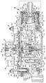
- FIG. 1 is a longitudinal sectional view of a pressure reducing valve for LPG fuel.
- FIG. 2 is a longitudinal cross-sectional view of the pressure reducing valve for LPG fuel with a cut surface different from that of FIG.
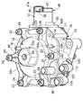
- FIG. 3 is a perspective view of a pressure reducing valve for LPG fuel.
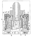
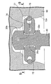
- FIG. 4 is an enlarged view of a portion indicated by an arrow 4 in FIG.
- FIG. 5 is a perspective view of the PTC heater unit.
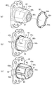
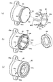
- FIG. 6 is a perspective view sequentially showing the process of assembling the PTC holding member and the PTC element to the inner case.
- FIG. 7 is a diagram sequentially illustrating the assembly process of the current-carrying part side assembly.
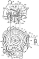
- FIG. 8 is an enlarged view of an arrow 8 in FIG.
- FIG. 9 is a cross-sectional view taken along line 9-9 of FIG.
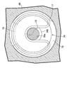
- FIG. 10 is an enlarged sectional view taken along line 10-10 of FIG.
- FIG. 11 is a perspective view of the gas passage cover member removed from the body.
- FIG. 12 is a perspective view of the heating fluid passage cover member removed from the body.
- FIG. 13 is a perspective view schematically showing the arrangement and communication state of a plurality of passage chambers in the low-pressure gas passage.
- FIG. 14 is a plan view schematically showing the arrangement and communication state of a plurality of passage chambers in the low-pressure gas passage.
- this LPG fuel pressure reducing valve is for reducing the pressure of LPG fuel and supplying it to an engine (not shown).
- the valve mechanism 15 and the valve mechanism 15 are opened and closed. And a diaphragm 16 for the purpose.
- the valve mechanism 15 is accommodated in a body 17 and faces a valve chamber 26 that communicates with the high-pressure gas passage 25, and a valve body 29 that can be seated on a valve seat 28 having a valve hole 27 opened at the center thereof;
- the valve shaft 30 is connected to the diaphragm 16 that operates according to the gas pressure on the downstream side of the valve seat 28 and is connected to the valve body 29.
- the body 17 is provided with a cylindrical portion 17 a disposed at the center of the body 17. One end of the cylindrical portion 17 a is opened to one surface side of the body 17 and the other end is closed by an end wall 32.
- the bottomed mounting hole 31 is provided in a stepped shape that gradually decreases in diameter toward the end wall 32 side.
- the valve seat member 20 is formed in a cylindrical shape having a flange portion 20a projecting inward in the radial direction at one end, and an annular shape in which a valve hole 27 is opened at the center portion of the flange portion 20a.
- the valve seat 28 is formed.
- the valve seat member 20 is screwed into the body 17 to be inserted and fixed in the axial intermediate portion of the mounting hole 31, and the valve seat member 20 is elastically attached to the inner surface of the mounting hole 31 in the axial direction intermediate portion.
- An annular first seal member 33 that comes into contact is mounted.
- the end wall 32 that closes the other end of the mounting hole 31 has a central portion that is disposed at a central portion in the cylindrical portion 17a with one end disposed at a position corresponding to the axially intermediate portion of the valve seat member 20.
- the other end of the cylindrical portion 17b is integrally connected to the end wall 32 so that a bottomed guide hole 34 having a diameter smaller than the inner diameter of the central cylindrical portion 17b is coaxially connected to the central cylindrical portion 17b.
- the central cylindrical portion 17b is fitted with a valve body 29 having a flange portion 29a projecting radially outward at one end so as to be slidable, and an annular second seal member 35 slidably contacting the outer periphery of the valve body 29.
- a valve body 29 having a flange portion 29a projecting radially outward at one end so as to be slidable, and an annular second seal member 35 slidably contacting the outer periphery of the valve body 29.
- an annular retainer 36 that prevents the second seal member 35 from being detached from the central cylindrical portion 17b is fitted and fixed to the opening end of the central cylindrical portion 17b.
- valve body 29 is driven in the axial direction by the diaphragm 16, and in order to improve the followability of the valve body 29 with respect to the operation of the diaphragm 16, the end wall 32 and the valve in the central cylindrical portion 17b.
- a coiled spring 37 that urges the valve body 29 is contracted on the side where the flange portion 29a is brought close to the valve seat 28.
- the set load of the spring 37 causes the valve body 29 to It is set to a very small value that allows the diaphragm 16 to follow.
- An annular third seal member 38 that can be seated on the valve seat 28 is attached to the flange portion 29a.
- valve shaft 30 that passes through the valve body 29 coaxially is coupled to the valve body 29, and one end side of the valve shaft 30 loosely penetrates the valve hole 27 and is connected to the diaphragm 16.
- the other end of the valve shaft 30 is slidably fitted into the guide hole 34.
- a valve chamber 26 is formed around the central cylindrical portion 17b between the valve seat member 20 inserted and fixed in an airtight manner in the intermediate portion of the cylindrical portion 17a and the end wall 32.
- the body 17 has an inlet-side connection hole 40 that opens on the side surface of the body 17, and a high-pressure gas passage that opens at one end to the inner end of the inlet-side connection hole 40 and communicates the other end with the valve chamber 26. 25 are provided.
- a PTC heater unit 41 is attached to the side surface of the body 17 at a position corresponding to the inlet side connection hole 40.
- the PTC heater unit 41 includes a metal inner case 42 fastened to the side surface of the body 17, a plurality of, for example, six PTC elements 43, 43. And a cylindrical outer case 45 and a current-carrying portion side assembly 48 that covers the inner case 42 with the PTC elements 43, 43...
- the inner case 42 includes a base cylinder part 42a having an inner peripheral surface that is continuous with the inner periphery of the inlet side connection hole 40 of the body 17, and one end of the base cylinder part 42a.
- An inward flange portion 42b projecting radially inward from the inner side, a connecting tube portion 42c projecting axially outwardly from the inner periphery of the inward flange portion 42b, and a radial direction from the other end of the base tube portion 42a
- the body 17 is integrally formed with a flange portion 42 d that projects outward, and the flange portion 42 d has an annular fourth seal member 49 interposed between the flange portion 42 d and the side surface of the body 17.
- the base cylinder portion 42a is directly connected to the body 17 so as to be detachable.
- the outer peripheral surface of the base cylindrical portion 42a is polygonal so as to form a plurality of flat, for example, six support surfaces 51, 51... For abutting and supporting the PTC elements 43, 43.
- it is formed in a hexagonal shape, and the plurality of PTC elements 43, 43,... Arranged on the outer peripheral surface of the base cylinder part 42a are also arranged in a polygonal shape when viewed from the direction along the axis of the base cylinder part 42a. It will be.
- the support surfaces 51, 51... are formed as inclined surfaces that are inclined so as to approach the center of the base cylinder part 42a toward the one end side in the axial direction of the base cylinder part 42a. That is, as shown in FIG. 4, a distance L1 from the support surface 51 on one end side in the axial direction of the base cylinder portion 42a to the central axis line of the base cylinder portion 42a is equal to the distance in the other end side in the axial direction of the base cylinder portion 42a.
- the distance L2 is set to be smaller than the distance L2 from the support surface 51 to the central axis of the base cylinder portion 42a (L1 ⁇ L2).
- an annular PTC holding member 52 made of synthetic resin is brought into contact with the flange portion 42d from one axial end side of the base cylinder portion 42a.
- the end portions of the PTC elements 43, 43... Arranged on the support surfaces 51, 51... On the outer peripheral surface of the base cylinder portion 42a are shown in FIG. In this manner, the PTC holding member 52 is brought into contact.
- the portion of the outer peripheral surface of the base cylindrical portion 42a where the PTC elements 43, 43,... Are arranged and the inner periphery of the PTC holding member 52 are formed in a polygonal shape corresponding to each other, for example, a hexagonal shape.
- a plurality of protrusions 52a, 52a,..., which are arranged at positions corresponding to the respective corners and protrude on the opposite side to the flange part 42d, are provided to protrude from the PTC holding member 52, and these protrusions 52a, 52a,.
- the plurality of PTC elements 43, 43,... Arranged on the outer peripheral surface of the base cylinder portion 42a are arranged between each other.
- the energizing member 44 has a plurality of electrode portions that individually and resiliently contact a plurality of PTC elements 43, 43,... Disposed on the outer peripheral surface of the base cylinder portion 42a. 44a, 44a ..., an annular assembly 44b for connecting the electrodes 44a, 44a ... in common, and a terminal 44c having one end connected to the assembly 44b, each of the electrode portions 44a, 44a ... Positioning projections 44d, 44d,... Projecting outward are projected from the central portion 44b at the central portion.
- the outer case 45 made of synthetic resin is formed in a cylindrical shape so as to hold the plurality of electrode portions 44 a, 44 a... On the inner peripheral surface, and the energization member 44 is provided at one end of the outer case 45. Are provided with a plurality of positioning notches 53, 53... For fitting the positioning protrusions 44d, 44d,... In the circumferential direction at the other end of the outer case 45.
- a pair of mounting projections 45a and 45a projecting laterally from the side are attached to the flange portion 42d of the inner case 42 by bolts 54 and 54, respectively.
- the collective portion 44b that is continuously connected to the plurality of electrode portions 44a, 44a,... Arranged inside the outer case 45 is arranged on one end side in the axial direction of the outer case 45, and one of the terminal portions 44c.
- one end side of the outer case 45 is covered with a mold portion 47 made of synthetic resin, so that at least the energizing member 44, An energization portion side assembly 48 including the outer case 45 and the mold portion 47 is configured.
- the collecting portion 44b of the energizing member 44 is sandwiched between one end of the outer case 45 as shown in FIGS. 7B and 7C.
- the energizing member holding ring 46 is fitted, and the mold part 47 is formed to cover the energizing member holding ring 46. That is, the energization portion side assembly 48 includes the energization member 44, the outer case 45, the energization member holding ring 46, and the mold portion 47.
- the mold part 47 is integrally formed with a connector part 47a in which a part of the terminal part 44c is arranged as a connector terminal 55.
- the base cylinder portion 42a of the inner case 42 in a state where the PTC elements 43, 43,... Are arranged on the outer peripheral surface is fitted to the energizing portion side assembly 48 from one end side in the axial direction.
- the annular fifth and sixth seal members 56 and 57 are interposed between the outer peripheral portions at both ends of the inner case 42 and both ends of the current-carrying portion side assembly 48.
- a pipe member 58 for guiding LPG fuel is attached to the connection case at one end of the inner case 42 coaxially and airtightly with the base cylinder portion 42a by, for example, screwing, and the pipe member 58 and the high-pressure gas A gap passage 60...
- Constituting at least a part of the heating gas passage 59 connecting between the passages 25 is an inner peripheral surface of the base cylinder portion 42a and an outer peripheral surface of the insertion cylinder 61 inserted into the base cylinder portion 42a. Formed between.
- the insertion tube 61 is formed in a bottomed cylindrical shape with one end open and the other end closed, and is inserted into the base tube portion 42a so as to open the side opposite to the body 17. Moreover, at both ends of the insertion tube 61, projections 61a, 61b for determining the axial position of the insertion tube 61 in the base tube portion 42a are projected, and one projection 61a ...
- the inner cylinder 42 protrudes from a plurality of locations on one end of the insertion tube 61 so as to abut against the inward flange portion 42b, and the other projection 61b forms the inner end of the inlet side connection hole 40. It protrudes from the other end of the insertion tube 61 so as to contact an end wall 40 a formed on the body 17.
- one of the inner peripheral surface of the base tube portion 42a and the outer peripheral surface of the insertion tube 61 in this embodiment, the outer peripheral surface of the insertion tube 61, the inner peripheral surface of the base tube portion 42a and the outer periphery of the inner tube portion.
- a plurality of ribs 62 are provided to protrude from the inner peripheral surface of the base cylinder portion 42a with their tips abutted in the circumferential direction. Gap passages 60 are respectively formed.
- the inner peripheral surface of the base tube portion 42a and the outer peripheral surface of the insertion tube 61 are formed in a tapered shape having a smaller diameter toward the one side in the axial direction, and the insertion tube 61 is formed from one end side in the axial direction. It is inserted into the base cylinder part 42a.
- a passage portion 63 communicating with the high-pressure gas passage 25 of the body 17 is formed between the body 17 and the insertion cylinder 61 so as to be a part of the heating gas passage 59, and the gap The passages 60 ... communicate with the high-pressure gas passage 25 through the passage portion 63.
- the pipe member 58 is integrally provided with a rush pipe section 58a having an outer diameter smaller than the inner diameter of the insertion cylinder 61 and coaxially inserted into the insertion cylinder 61.
- the metal filter 64 is fitted and fixed to the inner end portion of the portion 58a, for example, by pressing the outer peripheral portion of the filter 64 into the inner periphery of the inner end portion of the entry pipe portion 58a.
- the gas passage cover member 18 is fastened to the outer peripheral portion of the body 17 so as to fit one end of the cylindrical portion 17a of the body 17, and the cylindrical portion 17a.
- a decompression chamber 66 communicating with the valve hole 27 is formed between the body 17 and the gas passage cover member 18 inside.
- a guide cylinder portion 18 a extending coaxially with the valve hole 27 and extending toward the decompression chamber 66 is integrally provided at the center portion of the gas passage cover member 18.
- a diaphragm rod 68 coupled to the central portion of the diaphragm 16 is slidably fitted to the guide tube portion 18a, and an annular first ring is slidably contacted with the inner periphery of the guide tube portion 18a.
- 7 seal member 67 is mounted, and one end of the valve shaft 30 is connected to the diaphragm rod 68.
- the diaphragm rod 68 sandwiches a first retainer 69, which is a separate body from the diaphragm rod 68, with a central portion of one surface of the diaphragm 16, and a shaft portion 68a provided coaxially with the diaphragm rod 68 is provided.
- the diaphragm rod 68 passes through the diaphragm 16 and the second retainer 70 that contacts the center of the other surface of the diaphragm 16, and the shaft portion 68 a is caulked to engage with the second retainer 70, so that the diaphragm rod 68 of the diaphragm 16 is engaged.
- the first and second retainers 69 and 70 are sandwiched between the center portion and the center portion of the diaphragm 16 so that the diaphragm 16, the first retainer 69, the second retainer 70, and the diaphragm rod 68 are connected to each other.
- the diaphragm rod 68 is coaxially provided with an insertion recess 72 opened to the valve mechanism 15 side.
- One end portion of the valve shaft 30 has a reduced diameter shaft portion 30a and the contraction shaft portion 30a.
- a pair of diameter-enlarged shaft portions 30b and 30c having a larger diameter than the reduced-diameter shaft portion 30a are provided on both axial sides of the diameter shaft portion 30a.
- it has an engagement recess 73 that is wider than the outer diameter of the reduced diameter shaft portion 30a and smaller than the outer diameters of the two enlarged diameter shaft portions 30b and 30c and opens to one side, and has a substantially transverse cross section.
- a holding plate 74 formed in a U-shape holds the one end portion of the valve shaft 30 in an axially incapable relative movement by loosely inserting the reduced-diameter shaft portion 30a into the engaging recess 73. It is inserted into the insertion recess 72.
- An arc-shaped first engagement groove 76 is provided on the outer periphery of the holding plate 74, and an annular second engagement groove provided on the inner periphery of the insertion recess 72 corresponding to the first engagement groove 76.
- a groove 77 is provided, and an engagement ring 78 that allows expansion and contraction along the radial direction of the valve shaft 30 is engaged with the first and second engagement grooves 76 and 77.
- valve shaft 30 when connecting the valve shaft 30 to the diaphragm rod 68, the valve shaft 30 is connected to the diaphragm rod 68 of the diaphragm assembly 71 assembled in advance, and at this time, one end of the valve shaft 30 is held.
- the engagement ring 78 is inserted into the insertion recess 72 in a state where the engagement ring 78 is attached to the first engagement groove 76 of the holding plate 74 in the state, so that the engagement ring 78 becomes the first and second engagement grooves 76, 77.
- the valve shaft 30 is connected to the diaphragm rod 68.
- a guide surface 72a for inserting the holding plate 74 is formed at the opening end of the insertion recess 72 as a tapered surface having a smaller diameter as it goes inward.
- the engagement ring 78 is substantially C-shaped, and the engagement ring 78 is arranged so that its opening end is located at a position shifted from one opening end of the engagement recess 73.
- the first engagement groove 76 and the second engagement groove 77 are engaged.
- a pressure acting chamber 80 is formed between the gas passage cover member 18 and one surface of the diaphragm 16, and a spring chamber 82 is formed between the other surface of the diaphragm 16 and the diaphragm cover 22. Is biased by the coiled diaphragm spring 83 toward the side of reducing the volume of the pressure acting chamber 80, but the spring load of the diaphragm spring 83 can be adjusted.
- the shaft portion 68a of the diaphragm rod 68 that is connected to the valve body 29 via the valve shaft 30 and is coupled to the central portion of the diaphragm 16 is provided with a male screw 84 on the outer peripheral surface and the diaphragm rod 68.
- An adjustment screw 86 provided with an engagement recess 85 on the opposite end face is fitted and supported in the spring chamber 82 so as to be able to rotate about the axis, and rotates about an axis coaxial with the rotation axis of the adjustment screw 86.
- the male screw 84 on the outer periphery of the adjusting screw 86 is screwed on the inner periphery of the spring receiving member 87 accommodated in the spring chamber 82, which can be moved in the axial direction, although engaged with the inner periphery of the diaphragm cover 22.
- the diaphragm cover 22 has a cylindrical portion 22a having a non-circular cross-sectional shape as shown in FIG. 10, and is formed in a cap shape having one end closed by an end wall 22b.
- the cylindrical portion 22a is engaged with the inner periphery of the cylindrical portion 22a while allowing the cylindrical portion 22a to move in the direction along the axial line and disabling rotation around the axial line.
- the diaphragm cover 22 is provided with a negative pressure introducing pipe 91 that communicates with the spring chamber 82, and a pipe line (not shown) for guiding the intake negative pressure of the engine is connected to the negative pressure introducing pipe 91. Is done.
- the body 17 is provided with a circular gas passage groove 92 surrounding the cylindrical portion 17 a provided integrally with the body 17 so as to open on one surface of the body 17.
- the gas passage cover member 18 attached to one surface of the body 17 so as to cover the gas passage groove 92 and the gas passage groove 92 constitute a low pressure gas passage 93.
- An annular eighth seal member 94 is interposed between the body 17 and the gas passage cover member 18 on the outside.
- an opening 95 that allows the decompression chamber 66 formed in the cylindrical portion 17a to communicate with the low-pressure gas passage 93 cuts out a part of the cylindrical portion 17a.
- An extension wall 96 that extends in the tangential direction with one end connected to the cylindrical portion 17 a on one side of the opening 95 is connected to the outer peripheral portion of the body 17.
- a protrusion 98 that forms a fitting groove 97 into which one end of the cylindrical portion 17a and the extension wall portion 96 is fitted to the gas passage cover member 18 is connected to the cylindrical portion 17a and the extension. It protrudes so as to have a shape corresponding to the shape of the wall portion 96.
- the LPG fuel that has flowed out of the decompression chamber 66 into the low-pressure gas passage 93 circulates in the low-pressure gas passage 93 so as to make a round around the cylindrical portion 17a, and the starting point PS of the low-pressure gas passage 93 is
- the extension wall 96 is set on one side where the opening 95 is disposed, and the end point PE of the low-pressure gas passage 93 is set on the other side of the extension wall 96.
- valve hole 101 is formed in a bottomed cylindrical shape having a tip closed portion, and is provided integrally with the gas passage cover member 18 so as to enter the low-pressure gas passage 93, and the valve hole 101 includes A valve body 104 that has a seal portion 103 that can be closed at the tip and is slidably fitted to the valve housing 102, and a connecting pipe portion 105a that coincides with each other by press-fitting into the open end of the valve housing 102.
- the lid member 105 is fitted and fixed, and the spring 106 is contracted between the lid member 105 and the valve body 104.
- the valve body 104 is in a state where the valve hole 101 is opened. Is formed to a LPG fuel discharged from the bore 101 may then flow to the connecting tube portion 105a side.
- a cylindrical portion 109 that enters the low-pressure gas passage 93 so as to form a communication passage 108 for causing the pressure in the low-pressure gas passage 93 to act on the pressure working chamber 80 facing one surface of the diaphragm 16 is provided.
- the gas passage cover member 18 is provided integrally with the low pressure gas passage 93 near the end point PE.
- a concave portion 112 having a diameter larger than that of the gas passage groove 92 is provided on the other surface side of the body 17, and the body 17 has a circular shape at a position substantially corresponding to the outer periphery of the gas passage groove 92.
- the wall 114 is integrally provided, and one end 114a of the inner arc wall 114 is disposed at a position shifted to one side in the circumferential direction from the one end 113a of the outer arc wall 113, and the other end 113b of the outer arc wall 113 is peripheral.
- the other end 114b of the inner arc wall 114 is disposed at a position shifted in one direction.
- the outer end of the first radial wall 115 extending in the radial direction of the recess 112 is disposed at a right angle at one end 113a of the outer arc wall 113 so as to be disposed on the other circumferential side of the one end 114a of the inner arc wall 114.
- the inner end of the first radial wall 115 is connected to the end wall 32 that closes the other end of the mounting hole 31.
- the other end 114b of the inner arc wall 114 has a second radial wall 116 extending parallel to the first radial wall 115 so as to be disposed on one side in the circumferential direction of the other end 113b of the outer arc wall 113.
- the inner end is connected at right angles
- the outer end of the second radial wall 116 is connected at right angles to the body 17 on the outer periphery of the recess 112.
- the body 17 is provided with a partition wall 117 that connects the outer periphery of the intermediate arc wall 113 and the outer periphery of the recess 112 at a right angle.
- the heating fluid passage groove 111 is formed by the recess 112, the outer arc wall 113, the inner arc wall 114, the first radial wall 115, the second radial wall 116, and the partition wall 117.
- the heating fluid passage 110 formed between the heating fluid passage groove 111 and the heating fluid passage cover member 19 is configured such that the engine cooling water flowing into the heating fluid passage 110 on one side of the partition wall 117 flows outside the arc wall 113.
- a cooling water inlet pipe 118 that leads to the heating fluid passage 110 on one side of the partition wall 117 so as to introduce engine cooling water into the heating fluid passage 110, and the heating fluid passage 110.
- the cooling water outlet pipe 119 communicating with the heating fluid passage 110 on the other side of the partition wall 117 is liquid-tightly fitted so that the engine cooling water is led out from the cooling water inlet pipe 118 and the cooling water outlet pipe.
- the fitting holding plate 120 that holds the fitting state of the 119 to the body 17 in common is fastened to the body 17 with bolts 121.
- An annular ninth seal member 122 is interposed between the body 17 and the heating fluid passage cover member 19 outside the heating fluid passage 110.
- a single passage longitudinal protruding wall 125 extending in an arc shape along the reference flow direction 124 of the LPG fuel from the start point PS to the end point PE of the low pressure gas passage 93,
- the low pressure gas passage 93 is adjacent to each other such that a plurality of passage chambers 127... And the passage chambers 127.
- a plurality of first and second communication passages 128, 129, which communicate with each other between the passage chambers 127, are the body 17 of the valve housing 21, the gas passage cover member 18, the passage longitudinal projecting wall 125, and the passages.
- the first and second communication passages 128, 129, ... are formed in cooperation with the width direction projecting walls 126 ..., sequentially from the starting point PS of the low-pressure gas passage 93 through the plurality of passage chambers 127, zigzag. It arrange
- the low pressure gas passage 93 is composed of a gas passage groove 92 provided in the body 17 and the gas passage cover member 18 covering the gas passage groove 92.
- the bottom wall 92a and the gas passage cover member 18 are respectively provided with any one of the passage longitudinal direction protruding wall 125 and the passage width direction protruding wall 126, and the bottom of the gas passage groove 92.
- One of the passage longitudinal projecting wall 125 and the passage width projecting wall 126 Projects from one of the wall 92 a and the gas passage cover member 18, and the bottom wall 92 a of the gas passage groove 92 and the gas passage.
- the other of the passage longitudinal direction protruding wall 125 and the passage width direction protruding wall 126 ...
- a first communication passage 128 is formed between the distal end of the passage longitudinal projecting wall 125 and the gas passage cover member 18, and the gas passage groove 92 is formed at the distal end of the passage width projecting wall 126.
- each passage chamber 127 in the reference flow direction 124 is set to be larger than the width of each passage chamber 127 in the width direction of the low-pressure gas passage 93, and allows the engine coolant to flow.
- the heating fluid passage 110 is a second of the gas passage cover member 18 which is a pair of gas passage walls facing the low-pressure gas passage 93 in the projecting direction of the passage longitudinal projecting wall 125 and the bottom wall 92a of the gas passage groove 9.
- the bottom wall 92a which is a gas passage wall on the side of the communication passage 129, is disposed at a position sandwiched between the low pressure gas passage 93.
- the passage longitudinal direction protruding wall 125 and the passage width direction protruding wall 126... are inserted into the low pressure gas passage 93 as described above, and the body 17, the gas passage cover member 18, and the passage longitudinal direction protruding wall. 125 and the passage width direction projecting wall 126..., And the plurality of passage chambers 127... And the plurality of first and second communication passages 128.
- the LPG fuel is orthogonal to the flow along the width direction of the low-pressure gas passage 93 and the width direction of the low-pressure gas passage 93 as shown by the white arrows in FIGS. 13 and 14.
- the low-pressure gas passage 93 is circulated in a zigzag manner through a three-dimensional distribution path formed by a combination of the flow in the direction.
- a back pressure chamber 132 is formed between the end wall 32 and the valve body 29 in the small diameter cylindrical portion 17 b of the body 17 so that the back surface of the valve body 29 faces.
- a communication hole 133 for communicating the chamber 132 with the low-pressure gas passage 93 is provided in the body 17 so as to penetrate the low-pressure gas passage 93, and an outer end opening of the communication hole 133 is formed by a lid member 134. Closed airtight.
- the communication hole 133 also penetrates the passage longitudinal projecting wall 125, and the passage longitudinal projecting wall 125 is basically formed in a hollow shape so as to introduce engine cooling water therein. However, only the portion of the passage longitudinal projecting wall 125 where the communication hole 133 is provided is solid.
- All the LPG fuel flowing through the heating gas passage 59 is formed by using the inner peripheral surface of the base cylindrical portion 42a, which is the outer wall surface of the gap passage 60, as a heat radiating surface. It is possible to increase the heating efficiency of the LPG fuel so as to flow in the vicinity of the radiating surface.
- the plurality of flat plate-like PTC elements 43 are arranged on the outer peripheral surface of the base cylinder part 42a so as to have a polygonal shape when viewed from the direction along the axis of the base cylinder part 42a. It is possible to dispose a plurality of inexpensive PTC elements 43... That are in the form of a flat plate so as to increase the heating efficiency of the LPG fuel.
- a plurality of ribs 62 are provided on the outer peripheral surface of the insertion cylinder 61 so as to abut on the inner peripheral surface of the base cylinder portion 42a at intervals in the circumferential direction. Since the gap passages 60 are respectively formed, the radial position of the insertion tube 61 with respect to the base tube portion 42a can be easily determined by reliably forming the gap passages 60 between the base tube portion 42a and the insertion tube 61. Can do.
- the inner peripheral surface of the base tube portion 42a and the outer peripheral surface of the insertion tube 61 are formed in a tapered shape having a smaller diameter toward the one side in the axial direction, and the insertion tube 61 extends from the one end side in the axial direction to the base tube portion. Since it is inserted into 42a, it becomes easy to insert the insertion cylinder 61 into the base cylinder part 42a and to position the insertion cylinder 61 within the base cylinder part 42a.
- the base cylinder portion 42a constitutes a part of the inner case 42 having a flange portion 42d fastened to the body 17, and is directly connected to the body 17 forming the passage portion 63 connected to the gap passage 60.
- the PTC heater unit 41 can be compactly attached to the LPG fuel pressure reducing valve.
- the projecting portions 61a and 61b provided at both ends in the axial direction of the insertion tube 61 define the axial position of the insertion tube 61 in the base tube portion 42a, and are inwardly provided on the base tube portion 42a. Since the flange 42b and the end wall 40a formed on the body 17 are brought into contact with each other, the insertion tube 61 can be easily positioned in the axial direction.
- the insertion cylinder 61 is formed in a bottomed cylindrical shape that opens one end in the axial direction and closes the other end in the axial direction, and is a rush pipe section integrally provided with a pipe line member 58 that is coaxially attached to the base cylinder section 42a.
- 58a has an outer diameter smaller than the inner diameter of the insertion cylinder 61 and is inserted into the insertion cylinder 61, and the filter 64 is fitted and fixed to the inner end of the rush pipe section 58a.
- a filter 64 for filtering LPG fuel guided into the gap passages 60 can be disposed while avoiding an increase in the size of the PTC heater unit 41 in the direction along the axis of the cylindrical portion 42a and the insertion cylinder 61.
- the filter 64 since the outer peripheral portion of the filter 64 made of metal is press-fitted into the inner periphery of the inner end portion of the entry pipe portion 58a, the filter 64 is fitted and fixed to the inner end portion of the entry pipe portion 58a with a simple configuration. be able to.
- the PTC heater unit 41 includes an inner case 42 having the base tube portion 42a, a plurality of PTC elements disposed on the outer peripheral surface of the base tube portion 42a, and the PTC elements 43 individually and elastically. That holds a plurality of electrode portions 44a sandwiching the PTC elements 43 between the current-carrying member 44 having a plurality of electrode portions 44a in contact with each other and the outer peripheral surface of the base cylinder portion 42a on the inner peripheral surface.
- the energizing member 44 includes a plurality of the electrode portions 44a, an annular aggregate portion 44b that connects the electrode portions 44a in common, and one end to the aggregate portion 44b. Is composed of a terminal portion 44c to which is connected.
- the collective portion 44b that is connected in common to the plurality of electrode portions 44a... Disposed inside the outer case 45 is disposed on one end side in the axial direction of the outer case 45 and a part of the terminal portion 44c.
- one end side of the outer case 45 is covered with a molded portion 47 made of synthetic resin, and at least the energizing member 44, the outer case
- the inner case 42 in a state in which the PTC elements 43 are arranged on the outer peripheral surface of the base cylindrical portion 42a is fitted into the energizing portion side assembly 48 composed of 45 and the mold portion 47.
- the connector portion 47a in which a part of the terminal portion 44c is arranged as the connector terminal 55 is integrally formed in the mold portion 47, the connector portion 47a can be formed with high productivity.
- the connector portion 47a is waterproof.
- the connector portion 47a since the annular sixth and seventh seal members 56 and 57 are interposed between the outer peripheral portions of both ends of the inner case 42 and both ends of the energizing portion side assembly 48, the connector portion 47a is waterproof.
- the power supply side connector is connected to the connector portion 47a, it is possible to prevent water and the like from entering between the inner case 42 and the energization portion side assembly 48.
- an energizing member holding ring 46 that sandwiches the gathering portion 44 b of the energizing member 44 between one end of the outer case 45 is fitted to one axial end portion of the outer case 45, and the mold portion 47 is connected to the energizing member holding ring 46. Since the energizing member holding ring 46 is fitted to one end of the outer case 45 and the energizing member 44 is held by the outer case 45, the mold portion 47 can be formed. Since the molten resin is prevented from entering the inside of the outer case 45 at the time of molding 47, the energization member holding ring 46 prevents the molding 47 from being molded.
- the portion of the outer peripheral surface of the base cylindrical portion 42a where the PTC elements 43 are arranged is formed as an inclined surface that is inclined so as to approach the central axis of the base cylindrical portion 42a toward the one end side in the axial direction of the base cylindrical portion 42a. Since the base cylinder part 42a is fitted to the energizing part side assembly 48 from one end side in the axial direction, the PTC heater unit 41 is assembled by fitting the inner case 42 to the energizing part side assembly 48. In addition, the electrode portions 44a can be easily brought into contact with the PTC elements 43, so that assembly is facilitated.
- a flange portion 42d that projects radially outward from the base tube portion 42a is integrally provided on the other axial end side of the inner case 42 made of metal, and an annular PTC holding member 52 made of synthetic resin is provided as the flange portion. 42d is brought into contact with one end side in the axial direction of the base cylinder part 42a, and the end part on the flange part 42d side of each PTC element 43 is brought into contact with the PTC holding member 52. Therefore, each PTC is held by the PTC holding member 52. While positioning the elements 43 in the axial direction, the PTC holding member 52 can block the current that tends to flow from the electrode portions 44a to the flange portion 42d through the PTC elements 43 when energized. The heat generation efficiency can be increased.
- the portion on the outer peripheral surface of the base cylinder portion 42a where the PTC elements 43 are arranged and the inner periphery of the PTC holding member 52 are formed in polygonal shapes corresponding to each other, and are located at positions corresponding to the respective corner portions of the polygon.
- a plurality of protrusions 52a that are arranged and protrude on the opposite side to the flange part 42d are provided on the PTC holding member 52, and a plurality of PTC elements 43 arranged on the outer peripheral surface of the base cylinder part 42a are disposed between each other.
- the PTC holding member 52 can also have a positioning function of each PTC element 43 along the circumferential direction of the base cylinder part 42a, and one component can have multiple functions. Thus, the increase in the number of parts can be suppressed.
- valve shaft 30 of the valve mechanism 15 is connected to a diaphragm rod 68 coupled to the central portion of the diaphragm 16.
- the reduced diameter shaft portion 30 a and the reduced diameter shaft portion 30 a are connected to one end portion of the valve shaft 30.
- a pair of diameter-expanded shaft portions 30b and 30c having a diameter larger than that of the diameter-reduced shaft portion 30a on both sides in the axial direction.
- a holding plate 74 having an engagement recess 73 having a width smaller than the outer diameter of 30c and opening to one side and having a substantially U-shaped cross section is formed in the engagement recess 73 and the reduced diameter shaft portion 30a.
- valve shaft 30 can be connected to the diaphragm rod 68 while allowing the shaft center to be shifted.
- the diaphragm 16 and the diaphragm 16 are attached to the diaphragm rod 68 that sandwiches a first retainer 69, which is a separate body from the diaphragm rod 68, with the center portion of one surface of the diaphragm 16.
- a shaft portion 68a penetrating through the second retainer 70 that contacts the central portion of the other surface is provided coaxially, and the shaft portion 68a is caulked and engaged with the second retainer 70, whereby the diaphragm 16, the first retainer 69, A diaphragm assembly 71 including at least the second retainer 70 and the diaphragm rod 68 is assembled in advance, and one end portion of the valve shaft 30 is attached to the diaphragm rod 68 of the diaphragm assembly 71 using a holding plate 74 and an engagement ring 78. Diaphragms in the manufacture of pressure reducing valves.
- the body 71 is assembled in advance in large quantities by caulking, and one end portion of the valve shaft 30 is connected to the diaphragm rod 68 of the diaphragm assembly 71 by using the holding plate 74 and the engagement ring 78, so that the valve shaft 30 is perpendicular to the valve shaft direction. It is possible to facilitate the assembly of the pressure reducing valve while allowing the inclination of the diaphragm 16 with respect to a smooth surface and the shift of the shaft center on the diaphragm 16 side and the shaft center on the valve element 29 side.
- a diaphragm rod 68 connected to the valve body 29 passes through the central portion of the diaphragm 16 and is coupled to the diaphragm 16.
- a male screw 84 is engraved on the outer peripheral surface and an end surface on the opposite side to the diaphragm rod 68.
- the adjustment screw 86 provided with the engagement recess 85 is capable of rotating around the axis so as to be fitted and supported by the diaphragm rod 68 in the spring chamber 82, and cannot be rotated around the axis coaxial with the rotation axis of the adjustment screw 86.
- a male screw 84 on the outer periphery of the adjustment screw 86 is screwed onto the inner periphery of a spring receiving member 87 that engages with the inner periphery of the diaphragm cover 22 but can be moved in the axial direction, and is accommodated in the spring chamber 82.
- a diaphragm spring 83 that is a coil spring is contracted between the receiving member 87 and the diaphragm cover 22.
- the spring load of the diaphragm spring 83 that exerts a spring force that urges the diaphragm 16 toward the side of reducing the volume of the pressure acting chamber 80 is applied to the engagement recess 85 in order to change the axial position of the spring receiving member 87.
- the adjustment screw 86 is rotated to move the spring receiving member 87 in the direction along the axis of the adjustment screw 86 so that the diaphragm spring 83 can be expanded and contracted.
- a tool insertion hole 88 is provided in the diaphragm cover 22 at a position facing the end face where the mating recess 85 is provided, and a cap 89 for closing the tool insertion hole 88 is attached to the diaphragm cover 22.
- the adjustment screw 86 is accommodated in the spring chamber 82 and the tool insertion hole 88 is closed by the cap 89, the adjustment screw 87 is not visible in appearance, and the adjustment screw 87 is not desired by the end user. The possibility of being manipulated is reduced.
- the passage extends in the longitudinal direction of the passage extending in the reference flow direction 124 of the LPG fuel from the start point PS to the end point PE of the low-pressure gas passage 93.
- a wall 125 and a plurality of passage width direction protruding walls 126 extending in the width direction of the low pressure gas passage 93 perpendicular to the reference flow direction 124 are provided in the valve housing 21 so as to enter the low pressure gas passage 93.
- a plurality of first and second communication passages 128, 129 communicating between the passage chambers 127 adjacent to each other so that LPG fuel sequentially flows through the passage chambers 127.
- first and second communication passage as through the zigzag circulating a LPG fuel from the starting point PS of the low-pressure gas passage 93 up to the end point PE 128 ..., 129 ... are arranged.
- the flow path of the LPG fuel in the low pressure gas passage 93 is lengthened, the contact area of the LPG fuel to the valve housing 21, the passage longitudinal direction protruding wall 125, and the passage width direction protruding wall 126 is increased, and the LPG fuel is transmitted to the LPG fuel.
- Thermal efficiency is improved.
- the heat-transfer efficiency when there is much flow volume per unit time can be improved notably.
- first communication passage 128 connecting the passage chambers 127 and 127 adjacent to each other with the passage longitudinal protruding wall 125 sandwiched therebetween, and the adjacent passage chambers 127 and 127 sandwiching the passage width direction protruding wall 126 therebetween. Since the second communication passages 129 are connected to each other on the opposite side in the protruding direction of the passage longitudinal protruding wall 125, the LPG fuel not only circulates in the low pressure gas passage 93 in a zigzag manner, A bent path is also traced in a direction orthogonal to the width direction of the low-pressure gas passage 93.
- the low-pressure gas passage 93 passes through the three-dimensional flow path formed by combining the flow along the width direction of the low-pressure gas passage 93 and the flow in the direction perpendicular to the width direction of the low-pressure gas passage 93. Since it is configured to circulate, the distribution path of the LPG fuel is lengthened, the contact area of the LPG fuel with the heat transfer surface is increased, and the heat transfer efficiency to the LPG fuel is improved.
- the length of the passage chamber 127 in the reference flow direction 124 is set to be larger than the width of the passage chamber 127 in the width direction of the low-pressure gas passage 93, and the heat source is in the protruding direction of the passage longitudinal protruding wall 125.
- the engine cooling water is configured such that the bottom wall 92a on the second communication passage 129 side is sandwiched between the gas passage cover member 18 facing the low pressure gas passage 93 and the bottom wall 92a of the gas passage groove 92 between the low pressure gas passage 93. Therefore, the LPG fuel that passes through the second communication passages 129 and flows in the reference flow direction 124 is brought closer to the outer wall 92a for longer heat transfer efficiency. .
- passage longitudinal projecting wall 125 projects from the bottom wall 92a, which is the gas passage wall on the second communication passage 129 side, heat from the engine coolant is transmitted to the passage longitudinal projecting wall 125.
- the heat transfer efficiency can be improved by transferring more heat to the LPG fuel from the passage longitudinal projecting wall 125 extending in the reference flow direction 124 of the low pressure gas passage 93.
- the body 17 and the gas passage cover member 18 attached to one surface of the body 17 constitute at least a part of the valve housing 21, and the low-pressure gas passage 93 is provided in the gas passage groove 92 provided on one surface of the body 17. And the gas passage cover member 18 that covers the gas passage groove 92.
- the bottom wall 92a of the gas passage groove 92 and the gas passage cover member 18 have a passage longitudinal protruding wall 125 and a passage width. Since either one of the direction protruding walls 126 protrudes, the passage longitudinal direction protruding wall 125 and the passage width direction protruding wall 126 are easily formed.
- one of the passage longitudinal direction protruding wall 125 and the passage width direction protruding wall 126 Protrudes from one of the bottom wall 92 a of the gas passage groove 92 and the gas passage cover member 18, and the bottom wall 92 a of the gas passage groove 92. Since the other of the passage longitudinal direction protruding wall 125 and the passage width direction protruding wall 126... Protrudes from the other of the gas passage cover member 18, the passage longitudinal direction protruding wall 125 and the passage width direction protruding wall 126.
- the bottom wall 92a of the passage groove 92 and the gas passage cover member 18 are separately provided so that the passage longitudinal direction protruding wall 125 and the passage width direction protruding wall 126 are formed more easily.
- first communication passages 128 are formed between the distal end of the passage longitudinal protruding wall 125 and the bottom wall 92a of the gas passage groove 92 or the gas passage cover member 18, and the passage width direction protruding wall 126 ... Since the notches 130 for forming the second communication passages 129... Are formed between the gas passage cover member 18 and the bottom wall 92a of the gas passage groove 92 at the tip, the first and second communication passages are provided. 128... 129.
- a heating fluid passage groove 111 is provided on the other surface of the body 17 opposite to the low pressure gas passage 93, and a heating fluid passage 110 through which engine coolant flows is formed between the heating fluid passage groove 111. Since the heating fluid passage cover member 19 is attached to the other surface of the body 17 so as to cover the heating fluid passage groove 111, the heating fluid passage 110 can be easily formed, and is close to the low pressure gas passage 93. It is possible to arrange the heating fluid passage 110 to increase heat transfer efficiency and to configure the heating device compactly.
- At least one of the passage longitudinal direction protruding wall 125 and the passage width direction protruding wall 126 is made of engine cooling water. Heating is effectively performed, and at least one of the passage longitudinal direction protruding wall 125 and the passage width direction protruding wall 126... Can be effectively functioned as a heat transfer surface to the LPG fuel, thereby further improving the heat transfer efficiency.
- the projecting longitudinal direction of the bottom wall 92a of the gas channel groove 92 is projected. Since engine cooling water is guided into the protruding wall 125, a structure for guiding engine cooling water into the passage longitudinal protruding wall 125 can be easily configured.
- the gas passage cover member is a gas passage wall forming one side surface of the low pressure gas passage 93.
- a minute gap 131 is formed between the passage width direction protruding wall 126 projecting from 18, the passage longitudinal direction protruding wall 125, and the other gas passage wall of the low pressure gas passage 93.
- a small amount of LPG fuel flows in the gaps 131 as shown by thin line arrows in FIGS. 13 and 14 so that stagnation is less likely to occur, and downstream of the reference flow direction 124 in the passage width direction protruding wall 126.
- the above-described heating structure with engine cooling water to the pressure reducing valve having the low pressure gas passage 93 for circulating the LPG fuel after the pressure reduction, a pressure reducing valve for LPG fuel having excellent heat transfer efficiency can be obtained.
- the body 17 in which the valve mechanism 15 is accommodated is configured as a part of the valve housing 21 that is a passage forming body that forms the low-pressure gas passage 93, the pressure reducing valve for LPG fuel to which the heating device is attached is compactly configured. can do.
- the diaphragm rod 68 and the first retainer 69 are separated from each other, but the diaphragm rod may be integrally provided with a first retainer that abuts the central portion of one surface of the diaphragm 16.
Landscapes
- Engineering & Computer Science (AREA)
- Chemical & Material Sciences (AREA)
- General Engineering & Computer Science (AREA)
- Mechanical Engineering (AREA)
- General Chemical & Material Sciences (AREA)
- Combustion & Propulsion (AREA)
- Oil, Petroleum & Natural Gas (AREA)
- Chemical Kinetics & Catalysis (AREA)
- Physics & Mathematics (AREA)
- Fluid Mechanics (AREA)
- General Physics & Mathematics (AREA)
- Automation & Control Theory (AREA)
- Analytical Chemistry (AREA)
- Control Of Fluid Pressure (AREA)
- Valve Housings (AREA)
Priority Applications (5)
| Application Number | Priority Date | Filing Date | Title |
|---|---|---|---|
| KR1020127010988A KR101380306B1 (ko) | 2009-09-30 | 2010-09-10 | 감압 밸브의 밸브축 연결 구조 및 방법 |
| EP20100820329 EP2484947B1 (en) | 2009-09-30 | 2010-09-10 | Valve stem connection structure of pressure reducing valve and method therefor |
| CA 2774068 CA2774068C (en) | 2009-09-30 | 2010-09-10 | Valve stem connection structure of pressure reducing valve and method therefor |
| CN2010800436364A CN102575785B (zh) | 2009-09-30 | 2010-09-10 | 减压阀的阀杆连接结构和方法 |
| US13/395,372 US8714178B2 (en) | 2009-09-30 | 2010-09-10 | Valve stem connection structure of pressure reducing valve and method therefor |
Applications Claiming Priority (2)
| Application Number | Priority Date | Filing Date | Title |
|---|---|---|---|
| JP2009227905A JP5277133B2 (ja) | 2009-09-30 | 2009-09-30 | 減圧弁の弁軸連結構造および方法 |
| JP2009-227905 | 2009-09-30 |
Publications (1)
| Publication Number | Publication Date |
|---|---|
| WO2011040209A1 true WO2011040209A1 (ja) | 2011-04-07 |
Family
ID=43826037
Family Applications (1)
| Application Number | Title | Priority Date | Filing Date |
|---|---|---|---|
| PCT/JP2010/065607 Ceased WO2011040209A1 (ja) | 2009-09-30 | 2010-09-10 | 減圧弁の弁軸連結構造および方法 |
Country Status (7)
| Country | Link |
|---|---|
| US (1) | US8714178B2 (enExample) |
| EP (1) | EP2484947B1 (enExample) |
| JP (1) | JP5277133B2 (enExample) |
| KR (1) | KR101380306B1 (enExample) |
| CN (1) | CN102575785B (enExample) |
| CA (1) | CA2774068C (enExample) |
| WO (1) | WO2011040209A1 (enExample) |
Families Citing this family (8)
| Publication number | Priority date | Publication date | Assignee | Title |
|---|---|---|---|---|
| JP5982703B2 (ja) | 2012-07-02 | 2016-08-31 | 株式会社ケーヒン | 減圧弁 |
| JP6021767B2 (ja) * | 2013-09-04 | 2016-11-09 | 日本サーモスタット株式会社 | 液化ガス加温用ヒータ装置 |
| JP6218233B2 (ja) * | 2014-03-14 | 2017-10-25 | 株式会社ケーヒン | 減圧弁 |
| US9624960B2 (en) * | 2014-03-14 | 2017-04-18 | Keihin Corporation | Two-member connecting structure |
| NL2013490B1 (en) * | 2014-09-18 | 2016-09-29 | Anker Specials Benelux B V | Device for providing an additive fuel in gaseous state. |
| CN104405888B (zh) * | 2014-11-17 | 2017-08-04 | 杭州浙临阀门有限公司 | 补偿式密封减压阀 |
| JP7058736B2 (ja) * | 2018-07-05 | 2022-04-22 | 日立Astemo株式会社 | 制御弁、流量制御弁 |
| JP6964888B2 (ja) * | 2019-03-08 | 2021-11-10 | 株式会社不二工機 | 流量調整弁およびその組立方法 |
Citations (11)
| Publication number | Priority date | Publication date | Assignee | Title |
|---|---|---|---|---|
| JPS50147925U (enExample) * | 1974-05-24 | 1975-12-08 | ||
| JPS59188376U (ja) * | 1983-06-01 | 1984-12-13 | 株式会社 日本気化器製作所 | ダイヤフラム式開閉弁 |
| JPS60161475U (ja) * | 1984-04-04 | 1985-10-26 | 株式会社カイジョー | 振動振幅の調整手段を有するホ−ン |
| JPS6275180A (ja) * | 1985-09-30 | 1987-04-07 | Motoyama Seisakusho:Kk | メタルダイヤフラム弁 |
| JPS6388380A (ja) * | 1986-09-30 | 1988-04-19 | Fujikura Rubber Ltd | 空気作動弁 |
| JPH0297779A (ja) * | 1988-10-04 | 1990-04-10 | Eagle Ind Co Ltd | 弁の組立方法 |
| JPH02119504U (enExample) * | 1989-03-13 | 1990-09-26 | ||
| JP2005299873A (ja) * | 2004-04-15 | 2005-10-27 | Ckd Corp | 流体制御弁 |
| JP2008269459A (ja) * | 2007-04-24 | 2008-11-06 | Keihin Corp | 減圧弁 |
| JP2009112808A (ja) | 2007-11-02 | 2009-05-28 | Konami Gaming Inc | 多種のゲームスタイルを有するゲーミングマシン |
| JP2010198587A (ja) * | 2009-02-02 | 2010-09-09 | Keihin Corp | 減圧弁 |
Family Cites Families (13)
| Publication number | Priority date | Publication date | Assignee | Title |
|---|---|---|---|---|
| US3547143A (en) * | 1968-11-29 | 1970-12-15 | Lif O Gen Inc | Single stage pressure regulator |
| JPS5317492B2 (enExample) | 1974-05-20 | 1978-06-08 | ||
| US4240458A (en) * | 1978-04-26 | 1980-12-23 | Harper-Wyman Company | Excess pressure shutoff valve |
| JPS6088380A (ja) | 1983-10-19 | 1985-05-18 | Mitsubishi Electric Corp | レ−ダ装置 |
| JPS61161475U (enExample) * | 1985-03-29 | 1986-10-06 | ||
| US5288052A (en) | 1992-12-08 | 1994-02-22 | Cashco, Inc. | Self-draining sanitary control valve |
| US5443083A (en) | 1993-02-11 | 1995-08-22 | Itt Corporation | Pressure-reducing regulator for compressed natural gas |
| JP3802753B2 (ja) | 2000-12-11 | 2006-07-26 | 株式会社ケーヒン | 車両用燃料ガス供給装置 |
| US7165573B2 (en) | 2003-11-25 | 2007-01-23 | Itt Manufacturing Enterprises, Inc. | Compressed natural gas pressure regulator |
| MY144417A (en) * | 2004-02-10 | 2011-09-15 | Keihin Corp | Pressure reducing valve and regulator for gas |
| KR100873858B1 (ko) | 2006-12-14 | 2008-12-15 | 현대자동차주식회사 | 실린더 헤드의 체크 밸브 |
| JP5090824B2 (ja) * | 2007-08-29 | 2012-12-05 | 株式会社ケーヒン | 減圧弁 |
| CN100529490C (zh) * | 2007-12-17 | 2009-08-19 | 王青 | 冷媒单向阀及其冷媒防爆罐 |
-
2009
- 2009-09-30 JP JP2009227905A patent/JP5277133B2/ja not_active Expired - Fee Related
-
2010
- 2010-09-10 US US13/395,372 patent/US8714178B2/en not_active Expired - Fee Related
- 2010-09-10 WO PCT/JP2010/065607 patent/WO2011040209A1/ja not_active Ceased
- 2010-09-10 CN CN2010800436364A patent/CN102575785B/zh not_active Expired - Fee Related
- 2010-09-10 KR KR1020127010988A patent/KR101380306B1/ko not_active Expired - Fee Related
- 2010-09-10 EP EP20100820329 patent/EP2484947B1/en active Active
- 2010-09-10 CA CA 2774068 patent/CA2774068C/en not_active Expired - Fee Related
Patent Citations (11)
| Publication number | Priority date | Publication date | Assignee | Title |
|---|---|---|---|---|
| JPS50147925U (enExample) * | 1974-05-24 | 1975-12-08 | ||
| JPS59188376U (ja) * | 1983-06-01 | 1984-12-13 | 株式会社 日本気化器製作所 | ダイヤフラム式開閉弁 |
| JPS60161475U (ja) * | 1984-04-04 | 1985-10-26 | 株式会社カイジョー | 振動振幅の調整手段を有するホ−ン |
| JPS6275180A (ja) * | 1985-09-30 | 1987-04-07 | Motoyama Seisakusho:Kk | メタルダイヤフラム弁 |
| JPS6388380A (ja) * | 1986-09-30 | 1988-04-19 | Fujikura Rubber Ltd | 空気作動弁 |
| JPH0297779A (ja) * | 1988-10-04 | 1990-04-10 | Eagle Ind Co Ltd | 弁の組立方法 |
| JPH02119504U (enExample) * | 1989-03-13 | 1990-09-26 | ||
| JP2005299873A (ja) * | 2004-04-15 | 2005-10-27 | Ckd Corp | 流体制御弁 |
| JP2008269459A (ja) * | 2007-04-24 | 2008-11-06 | Keihin Corp | 減圧弁 |
| JP2009112808A (ja) | 2007-11-02 | 2009-05-28 | Konami Gaming Inc | 多種のゲームスタイルを有するゲーミングマシン |
| JP2010198587A (ja) * | 2009-02-02 | 2010-09-09 | Keihin Corp | 減圧弁 |
Non-Patent Citations (1)
| Title |
|---|
| See also references of EP2484947A4 * |
Also Published As
| Publication number | Publication date |
|---|---|
| JP2011076424A (ja) | 2011-04-14 |
| CN102575785A (zh) | 2012-07-11 |
| EP2484947A4 (en) | 2013-11-20 |
| CN102575785B (zh) | 2013-12-11 |
| KR20120076363A (ko) | 2012-07-09 |
| EP2484947B1 (en) | 2014-11-19 |
| US20120175545A1 (en) | 2012-07-12 |
| CA2774068C (en) | 2014-09-09 |
| EP2484947A1 (en) | 2012-08-08 |
| JP5277133B2 (ja) | 2013-08-28 |
| KR101380306B1 (ko) | 2014-04-02 |
| CA2774068A1 (en) | 2011-04-07 |
| US8714178B2 (en) | 2014-05-06 |
Similar Documents
| Publication | Publication Date | Title |
|---|---|---|
| JP5277133B2 (ja) | 減圧弁の弁軸連結構造および方法 | |
| JP5162486B2 (ja) | 減圧弁 | |
| WO2011040208A1 (ja) | Ptcヒータユニットおよびlpg燃料用減圧弁 | |
| WO2010087475A1 (ja) | 減圧弁 | |
| JP5416533B2 (ja) | 減圧弁の弁軸連結構造および方法 | |
| WO2011040207A1 (ja) | Lpg燃料用加熱装置およびlpg燃料用減圧弁 | |
| JP5461138B2 (ja) | Ptcヒータユニット | |
| JP2011076423A (ja) | 減圧弁 | |
| JP5243289B2 (ja) | Lpg燃料の加熱装置 | |
| JP2010174869A (ja) | Lpg燃料の加熱装置 | |
| JP5135247B2 (ja) | 減圧弁の組立方法および減圧弁 | |
| JP2011202609A (ja) | ガスの加熱装置 | |
| JP2011202608A (ja) | ガスの加熱装置 | |
| JP2010174871A (ja) | Lpg燃料用減圧弁 | |
| JP2013096310A (ja) | Lpg燃料用減圧弁 | |
| JP2011204956A (ja) | ガスの加熱装置 | |
| JP2010176644A (ja) | ガス用減圧弁 | |
| JP2011202559A (ja) | ガスの加熱装置 |
Legal Events
| Date | Code | Title | Description |
|---|---|---|---|
| WWE | Wipo information: entry into national phase |
Ref document number: 201080043636.4 Country of ref document: CN |
|
| 121 | Ep: the epo has been informed by wipo that ep was designated in this application |
Ref document number: 10820329 Country of ref document: EP Kind code of ref document: A1 |
|
| WWE | Wipo information: entry into national phase |
Ref document number: 13395372 Country of ref document: US |
|
| WWE | Wipo information: entry into national phase |
Ref document number: 2774068 Country of ref document: CA |
|
| WWE | Wipo information: entry into national phase |
Ref document number: 2010820329 Country of ref document: EP |
|
| NENP | Non-entry into the national phase |
Ref country code: DE |
|
| WWE | Wipo information: entry into national phase |
Ref document number: 1201001358 Country of ref document: TH |
|
| WWE | Wipo information: entry into national phase |
Ref document number: 3686/CHENP/2012 Country of ref document: IN |
|
| ENP | Entry into the national phase |
Ref document number: 20127010988 Country of ref document: KR Kind code of ref document: A |