WO2011040104A1 - 内視鏡装置及び湾曲駆動制御方法 - Google Patents
内視鏡装置及び湾曲駆動制御方法 Download PDFInfo
- Publication number
- WO2011040104A1 WO2011040104A1 PCT/JP2010/061590 JP2010061590W WO2011040104A1 WO 2011040104 A1 WO2011040104 A1 WO 2011040104A1 JP 2010061590 W JP2010061590 W JP 2010061590W WO 2011040104 A1 WO2011040104 A1 WO 2011040104A1
- Authority
- WO
- WIPO (PCT)
- Prior art keywords
- bending
- plane
- distal end
- unit
- end side
- Prior art date
Links
Images


Classifications
-
- A—HUMAN NECESSITIES
- A61—MEDICAL OR VETERINARY SCIENCE; HYGIENE
- A61B—DIAGNOSIS; SURGERY; IDENTIFICATION
- A61B1/00—Instruments for performing medical examinations of the interior of cavities or tubes of the body by visual or photographical inspection, e.g. endoscopes; Illuminating arrangements therefor
- A61B1/00002—Operational features of endoscopes
- A61B1/00004—Operational features of endoscopes characterised by electronic signal processing
- A61B1/00006—Operational features of endoscopes characterised by electronic signal processing of control signals
-
- A—HUMAN NECESSITIES
- A61—MEDICAL OR VETERINARY SCIENCE; HYGIENE
- A61B—DIAGNOSIS; SURGERY; IDENTIFICATION
- A61B1/00—Instruments for performing medical examinations of the interior of cavities or tubes of the body by visual or photographical inspection, e.g. endoscopes; Illuminating arrangements therefor
- A61B1/00147—Holding or positioning arrangements
- A61B1/0016—Holding or positioning arrangements using motor drive units
-
- A—HUMAN NECESSITIES
- A61—MEDICAL OR VETERINARY SCIENCE; HYGIENE
- A61B—DIAGNOSIS; SURGERY; IDENTIFICATION
- A61B1/00—Instruments for performing medical examinations of the interior of cavities or tubes of the body by visual or photographical inspection, e.g. endoscopes; Illuminating arrangements therefor
- A61B1/005—Flexible endoscopes
- A61B1/0051—Flexible endoscopes with controlled bending of insertion part
- A61B1/0052—Constructional details of control elements, e.g. handles
-
- A—HUMAN NECESSITIES
- A61—MEDICAL OR VETERINARY SCIENCE; HYGIENE
- A61B—DIAGNOSIS; SURGERY; IDENTIFICATION
- A61B1/00—Instruments for performing medical examinations of the interior of cavities or tubes of the body by visual or photographical inspection, e.g. endoscopes; Illuminating arrangements therefor
- A61B1/005—Flexible endoscopes
- A61B1/009—Flexible endoscopes with bending or curvature detection of the insertion part
-
- A—HUMAN NECESSITIES
- A61—MEDICAL OR VETERINARY SCIENCE; HYGIENE
- A61B—DIAGNOSIS; SURGERY; IDENTIFICATION
- A61B1/00—Instruments for performing medical examinations of the interior of cavities or tubes of the body by visual or photographical inspection, e.g. endoscopes; Illuminating arrangements therefor
- A61B1/04—Instruments for performing medical examinations of the interior of cavities or tubes of the body by visual or photographical inspection, e.g. endoscopes; Illuminating arrangements therefor combined with photographic or television appliances
- A61B1/05—Instruments for performing medical examinations of the interior of cavities or tubes of the body by visual or photographical inspection, e.g. endoscopes; Illuminating arrangements therefor combined with photographic or television appliances characterised by the image sensor, e.g. camera, being in the distal end portion
-
- A—HUMAN NECESSITIES
- A61—MEDICAL OR VETERINARY SCIENCE; HYGIENE
- A61B—DIAGNOSIS; SURGERY; IDENTIFICATION
- A61B5/00—Measuring for diagnostic purposes; Identification of persons
- A61B5/06—Devices, other than using radiation, for detecting or locating foreign bodies ; determining position of probes within or on the body of the patient
- A61B5/061—Determining position of a probe within the body employing means separate from the probe, e.g. sensing internal probe position employing impedance electrodes on the surface of the body
- A61B5/062—Determining position of a probe within the body employing means separate from the probe, e.g. sensing internal probe position employing impedance electrodes on the surface of the body using magnetic field
-
- A—HUMAN NECESSITIES
- A61—MEDICAL OR VETERINARY SCIENCE; HYGIENE
- A61B—DIAGNOSIS; SURGERY; IDENTIFICATION
- A61B5/00—Measuring for diagnostic purposes; Identification of persons
- A61B5/06—Devices, other than using radiation, for detecting or locating foreign bodies ; determining position of probes within or on the body of the patient
- A61B5/061—Determining position of a probe within the body employing means separate from the probe, e.g. sensing internal probe position employing impedance electrodes on the surface of the body
- A61B5/064—Determining position of a probe within the body employing means separate from the probe, e.g. sensing internal probe position employing impedance electrodes on the surface of the body using markers
-
- A—HUMAN NECESSITIES
- A61—MEDICAL OR VETERINARY SCIENCE; HYGIENE
- A61B—DIAGNOSIS; SURGERY; IDENTIFICATION
- A61B5/00—Measuring for diagnostic purposes; Identification of persons
- A61B5/06—Devices, other than using radiation, for detecting or locating foreign bodies ; determining position of probes within or on the body of the patient
- A61B5/065—Determining position of the probe employing exclusively positioning means located on or in the probe, e.g. using position sensors arranged on the probe
-
- A—HUMAN NECESSITIES
- A61—MEDICAL OR VETERINARY SCIENCE; HYGIENE
- A61B—DIAGNOSIS; SURGERY; IDENTIFICATION
- A61B1/00—Instruments for performing medical examinations of the interior of cavities or tubes of the body by visual or photographical inspection, e.g. endoscopes; Illuminating arrangements therefor
- A61B1/00002—Operational features of endoscopes
- A61B1/00039—Operational features of endoscopes provided with input arrangements for the user
- A61B1/00042—Operational features of endoscopes provided with input arrangements for the user for mechanical operation
-
- A—HUMAN NECESSITIES
- A61—MEDICAL OR VETERINARY SCIENCE; HYGIENE
- A61B—DIAGNOSIS; SURGERY; IDENTIFICATION
- A61B1/00—Instruments for performing medical examinations of the interior of cavities or tubes of the body by visual or photographical inspection, e.g. endoscopes; Illuminating arrangements therefor
- A61B1/31—Instruments for performing medical examinations of the interior of cavities or tubes of the body by visual or photographical inspection, e.g. endoscopes; Illuminating arrangements therefor for the rectum, e.g. proctoscopes, sigmoidoscopes, colonoscopes
Definitions
- the present invention relates to an endoscope apparatus and a bending drive control method for electrically bending and driving a bending portion of an endoscope.
- An endoscope provided with an imaging means and a bendable bending portion on the distal end side of the insertion portion is widely used for inspection, diagnosis and the like in a body cavity.
- skill may be required to smoothly insert the insertion portion into a complexly bent body cavity such as the large intestine.
- a complexly bent body cavity such as the large intestine.
- flipping is generally used as an insertion procedure for removing the deflection of the transverse colon and linearizing it. Done.
- it is difficult to determine the direction in which the transverse colon is running from the endoscopic image so it is difficult to determine the direction to be curved and it is difficult to perform smooth insertion. there were.
- the present invention has been made in view of the above problems, and an endoscope apparatus and a bending device that can accurately drive the bending portion in an appropriate direction based on the bent insertion shape on the distal end side of the insertion portion.
- An object is to provide a drive control method.
- An endoscope apparatus includes an insertion portion provided with a bendable bending portion on the distal end side, A bending drive unit for electrically driving the bending unit; An insertion shape detection unit for detecting an insertion shape on the distal end side of the insertion unit; Based on the insertion shape information on the distal end side of the insertion portion by the insertion shape detection unit, the bent bending plane including the distal end side of the insertion portion in a state of being inserted into the bent tubular body cavity is estimated and estimated A bending control unit that performs control to drive the bending unit using information on a bending plane; It is characterized by comprising.
- the bending drive control method of the present invention includes a bending plane including the distal end side of the insertion portion when the distal end side of the insertion portion provided with the bendable bending portion is inserted along a bent shape in the tubular body cavity.
- a bending drive direction determining step for determining a bending drive direction for driving the bending portion to bend based on an intersection line between the bent plane and the virtual plane; It is characterized by comprising.
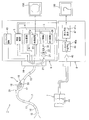
- FIG. 1 is a diagram showing an overall configuration of an endoscope apparatus according to a first embodiment of the present invention.
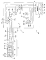
- FIG. 2 is a diagram illustrating a configuration of an endoscope and a bending control device.
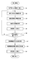
- FIG. 3 is a flowchart showing a processing procedure when an insertion portion is inserted into the large intestine.
- FIG. 4 is a flowchart showing a processing procedure for determining a bending drive direction in the case of a predetermined region.
- FIG. 5 is an explanatory view showing a state where the insertion portion is inserted to the transverse colon side through the splenic curvature in the large intestine.
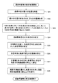
- FIG. 6 is a flowchart showing a processing procedure for estimating a bending plane and the like in the state of FIG. FIG.
- FIG. 7A is a diagram showing a first principal component direction and a second principal component direction calculated for five points set on the bending plane by principal component analysis.
- FIG. 7B is a diagram showing a first principal component direction and a third principal component direction perpendicular to the second principal component direction with respect to five points set on the bending plane by principal component analysis.
- FIG. 8 is an explanatory diagram illustrating a direction in which the bending portion is driven to bend from the current bending position on the pulley angle coordinate system.
- FIG. 9 shows a configuration of a bending control apparatus according to the second embodiment of the present invention.
- FIG. 10 is an explanatory diagram when the second bending portion is driven to bend.
- FIG. 11 is a flowchart illustrating a procedure of bending driving processing according to the second embodiment.
- FIG. 12 is an explanatory diagram when the distal end side of the insertion portion in the second embodiment is inserted into the large intestine.
- FIG. 13 shows the configuration of a bending control apparatus according to the third embodiment of the present invention.
- FIG. 14 is a flowchart illustrating a procedure of bending driving processing according to the third embodiment.
- FIG. 15 is an explanatory diagram when the distal end side of the insertion portion according to the third embodiment is inserted into the large intestine.
- FIG. 16 shows the configuration of a bending control apparatus according to the fourth embodiment of the present invention.
- FIG. 17 is an explanatory diagram when the first and second bending portions are driven to bend.
- FIG. 18 is an explanatory diagram when the distal end side of the insertion portion according to the fourth embodiment is inserted into the large intestine.
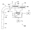
- an endoscope apparatus 1 includes an endoscope 2 that is inserted into a body cavity and the like, and a light source unit that supplies illumination light to the endoscope 2. 3.
- a video processor 6 including a signal processing unit 4 that performs signal processing on an imaging unit built in the endoscope 2, a bending control unit 5 that performs bending control of the bending unit of the endoscope 2, and the like.
- the endoscope apparatus 1 further includes a sense coil unit 7 that detects the position of a position detection source coil provided in the endoscope 2, and a detection signal from the sense coil unit 7.
- An insertion shape detection device 8 that detects an insertion shape of the insertion unit 11 and generates an image thereof; a monitor 10A that displays an endoscopic image captured by an imaging unit and an insertion shape detection image obtained by the insertion shape detection device 8; 10B.
- the endoscope 2 includes an elongated insertion portion 11 to be inserted into a body cavity, an operation portion 12 provided at the rear end of the insertion portion 11, and a universal cord 13 extending from the operation portion 12.
- the connector 14 at the rear end of the universal cord 13 is detachably connected to the video processor 6.
- the insertion portion 11 includes a hard distal end portion 15 provided at the distal end thereof, a bending portion 16 provided so as to be freely bent adjacent to the rear end of the distal end portion 15, and a rear end of the bending portion 16. And a long flexible tube portion 17 extending to the front end of the operation portion 12.
- the operation unit 12 includes a bending joystick 18 as a bending instruction operating means for instructing a bending direction and a bending angle of the bending unit 16, and selection of an automatic bending (automatic insertion) mode and a manual bending (manual insertion) mode.
- a mode selection switch 19 and a scope switch 20 for giving a still image display instruction and the like.
- the bending control unit 5 automatically determines the bending driving direction of the bending unit 16, and the operator simply pushes the insertion unit 11 into the deep side.
- the manual bending mode the surgeon operates the joystick 18 to instruct the bending driving direction of the bending portion 16, and the bending driving portion 5 changes the bending driving direction according to the instruction operation. Is determined as the bending drive direction with respect to. Then, the surgeon performs an operation of pushing the insertion portion 11 into the deep side.
- a light guide 21 that transmits illumination light is inserted into the insertion portion 11 of the endoscope 2, and the rear end of the light guide 21 protrudes from the connector 14 and becomes an incident end surface.
- Illumination light from the lamp 22 built in the light source unit 3 is incident on the incident end face through the diaphragm 23 and the condenser lens 24.
- the lamp 22 is lit by a lamp driving power source supplied from the lamp driving circuit 25 and generates illumination light.
- the aperture 23 is controlled by an aperture control circuit 26 so that an aperture amount (aperture amount) through which illumination light passes is controlled.
- the illumination light transmitted by the light guide 21 is emitted from the light guide distal end surface fixed to the distal end portion 15 of the insertion portion 11 to the outside via an illumination lens 27 (see FIG. 2) attached to the illumination window. Illuminate the subject such as the affected area.
- the distal end portion 15 is provided with an observation window (adjacent to the illumination window), and an imaging unit 31 is attached to the observation window.
- the image pickup unit 31 is attached to a lens frame (not shown), an objective lens 32 for forming an optical image of a subject, and a charge coupled device as an image pickup device in which the image pickup surface is arranged at an image formation position by the objective lens 32. (Abbreviated as CCD) 33.
- the cable connected to the CCD 33 is inserted through the insertion portion 11 and the like, and the rear end side thereof is connected to the CCD drive circuit 36 constituting the signal processing portion 4 via the electrical contacts of the connector 14 as shown in FIG. Connected to circuit 37.
- the CCD drive circuit 36 generates a CCD drive signal and applies the CCD drive signal to the CCD 33.
- the CCD 33 photoelectrically converts an optical image formed on the imaging surface by applying a CCD drive signal and outputs it as a CCD output signal.
- the CCD output signal is input to the video processing circuit 37.
- the video processing circuit 37 generates a video signal for displaying an optical image of the imaging surface of the CCD 33 as an endoscopic image, and outputs the video signal to the monitor 10A. An endoscope image is displayed on the display screen of 10A.
- the CCD 33 is disposed so as to have a predetermined relationship with the bending direction of the bending portion 16 in the distal end portion 15. Specifically, the upward direction of the imaging surface of the CCD 33 is the upward direction of the bending direction of the bending portion 16 in the vertical and horizontal directions.
- the video signal is input to the aperture control circuit 26, and the aperture control circuit 26 calculates the average brightness by, for example, integrating the luminance signal component of the video signal at a predetermined period.
- the opening amount of the diaphragm 23 is adjusted using a difference signal obtained by subtracting a reference value corresponding to appropriate brightness from the average brightness signal as a diaphragm control signal. Then, automatic light control is performed so that the amount of illumination light passing through the aperture 23 becomes a reference value.
- the video processing circuit 37 includes a dark part detection circuit 37a that detects the presence or absence of a dark part in the endoscopic image by image processing. Information on the detection (determination) of the presence or absence of dark parts by the dark part detection circuit 37 a is sent to the bending control unit 5.
- the bending control unit 5 When the automatic bending mode for automatically bending the insertion portion 11 is selected, the bending control unit 5 normally aims (directs) the tip portion 15 in the direction of the dark portion as a target position when the dark portion is inserted. Thus, the bending drive direction and the bending amount (bending angle) of the bending portion 16 are controlled. Further, in the manual insertion mode, the surgeon operates the joystick 18 so that the distal end portion 15 points in the direction of the dark portion as a target position when the dark portion is inserted, and the bending drive direction and the bending amount of the bending portion 16. Set (bending angle).
- a treatment instrument channel (not shown) is provided in the insertion section 11, and the rear end side of the treatment instrument channel communicates with a treatment instrument insertion port 39 provided near the front end of the operation section 12.
- a bending portion 16 is provided adjacent to the rear end of the distal end portion 15 of the insertion portion 11, and the bending control portion 5 provided in the video processor 6 is an electric bending driving mechanism 50 as shown in FIG. It is the structure which performs control.
- the bending control device 40 is configured by the bending drive mechanism 50 and the bending control unit 5 of FIG.
- portions adjacent to each other in the longitudinal direction of the bending portion 16 are rotatably connected by rivets 52.
- each bending piece 51 is determined by the position where the rivet 52 is provided, and the rivets 52 are alternately arranged in the left and right positions and the vertical position or at appropriate intervals, and the bending portion 16 is arbitrary in addition to the vertical direction and the horizontal direction. It can be bent in the direction of.
- angle wires (bending wires) 53u, 53d and 53l, 53r that are bent in the vertical direction and the horizontal direction are inserted into the insertion portion 11, and the tips of these angle wires 53u, 53d, 53l, and 53r are the leading ends. It is fixed to the part 15.
- the rear ends of the angle wires 53u, 53d and 53l, 53r are fixed to a vertical bending pulley 54a and a left / right bending pulley 54b disposed in the operation unit 12.
- the pulleys 54a and 54b are rotated in the forward and reverse directions by electric motors 55a and 55b that constitute a bending drive means for electrically bending the bending portion 16.
- the electric motors 55 a and 55 b are driven by a motor drive signal from the motor drive unit 56.
- the motor driving unit 56 is controlled by the bending control unit 5.
- FIG. 1 shows a configuration example in which the bending control unit 5 is provided inside the video processor 6, the bending control unit 5 is provided inside the endoscope 2 such as the inside of the operation unit 12. Also good.
- the electric motors 55a and 55b driven by the motor drive signal from the motor drive unit 56 rotate the pulleys 54a and 54b, and pull the angle wires 53u, 53d, 53l, and 53r by the rotation of the pulleys 54a and 54b, and the bending unit 16 Drive the curve.
- the pulling amounts of the angle wires 53u, 53d, 53l, and 53r are determined corresponding to the rotation angles of the pulleys 54a and 54b, and the bending portion 16 is bent corresponding to the pulling amounts. Therefore, the bending angle of the bending portion 16 can be detected by detecting the rotation angle of the electric motors 55a, 55b or the pulleys 54a, 54b or the pulling amount (movement amount) of the angle wires 53u, 53d, 53l, 53r. .
- encoders rotary encoders
- the rotation angle of the pulleys 54a and 54b in other words, the bending angle of the bending portion 16 corresponding to the rotation angle of the pulleys 54a and 54b can be detected.
- the encoders 57a and 57b form a curved shape detecting means for detecting the curved shape of the bending portion 16.
- a pulley angle or bending angle detection signal (detection value) based on the output signals of the encoders 57 a and 57 b is input to the motor drive unit 56.
- the motor drive unit 56 receives an instruction value of a bending drive direction and a bending angle by the joystick 18 as a bending instruction operation unit via the bending control unit 5.
- the motor driving unit 56 drives the electric motors 55a and 55b to rotate so that the detection values of the encoders 57a and 57b follow (match) the instruction values.
- the bending control section 5 gives an instruction value from the bending instruction operating means to the motor driving section 56, and the motor driving section 56 drives the electric motors 55a and 55b to bend so that the detected value of the bending angle becomes the instruction value.
- the portion 16 is bent to a specified bending angle.
- the operator performs an operation of tilting in an arbitrary bending direction, up and down, left and right, with the joystick 18 provided in the operation unit 12, so that the tilted direction becomes an instruction value for the bending drive direction, and the tilt angle is curved. It becomes the indicated value of the corner.
- the up and down joystick motor 58a and the left and right joystick motor 58b rotate in accordance with the tilted direction.
- the rotation angles are detected by the encoders 59a and 59b, and the detection signals of the encoders 59a and 59b are input to the bending control unit 5 as instruction values for the bending drive direction and the bending angle.
- the joystick motors 58 a and 58 b are controlled by the bending control unit 5, and detection signals from the encoders 59 a and 59 b are also input to the bending control unit 5.
- the bending control unit 5 outputs the instruction values for the bending driving direction and the bending angle as detection signals of the encoders 59a and 59b to the motor driving unit 56, and controls the operation thereof.
- source coils 41 are arranged along the longitudinal direction thereof at a predetermined interval, for example, and signal lines connected to the source coils 41 are electrical contacts of the connector 14 as shown in FIG. And is connected to a source coil drive circuit 43 provided in the video processor 6.
- the source coil drive circuit 43 sequentially applies an AC drive signal to each source coil 41 via a signal line, and generates an AC magnetic field around each source coil 41.
- a sense coil unit 7 including a plurality of sense coils 44 is disposed at a predetermined position in a peripheral portion of a bed on which a patient (not shown) on which the insertion portion 11 is inserted lies, and a plurality of sense coils are inserted. 44 detects the magnetic field generated by the source coil 41 arranged in the insertion portion 11.
- the detection signal from the sense coil 44 is amplified by the amplifier 45 in the insertion shape detection device 8 and then input to the source coil position calculation circuit 46, and is detected by the sense coil 44 by the source coil position calculation circuit 46.
- the position of each source coil 41 is calculated from the amplitude value and phase value in the obtained signal.
- the position information calculated by the source coil position calculation circuit 46 is input to the insertion shape calculation circuit 47.
- the insertion shape calculation circuit 47 detects an insertion shape (such as a bent shape) of the insertion portion 11 to be inserted into the body cavity from the shape obtained by connecting the calculated positions of the source coils 41, and detects the detected insertion shape.
- the insertion shape calculation circuit 47 has a function of an insertion shape detection unit 47a that detects an insertion shape including at least a bent shape on the distal end side of the insertion portion 11.
- the insertion shape image signal generated by the insertion shape calculation circuit 47 is input to the monitor 10B, and an insertion shape image when the distal end side of the insertion portion 15 is bent is displayed on the display screen. Further, information on the coordinates of the insertion shape including the case of the bent shape on the distal end side of the insertion portion 11 calculated by the insertion shape calculation circuit 47 is acquired by the bending control unit 5. As will be described later, when performing control for driving the bending portion 16 to bend, the bending control unit 5 uses information on the bending coordinates (as information on the coordinates of the insertion shape), particularly in a bent state on the distal end side of the insertion portion 11. To do. As shown in FIG.
- the source coil 41 is also installed in the distal end portion 15, and the source coil position calculation circuit 46 determines the position of the distal end portion 15 from the positions of the plurality of source coils 41 attached to the distal end portion 15. In addition to the position, a specific direction in the direction such as up and down, left and right in the circumferential direction of the tip 15 is calculated.
- the plurality of source coils 41 are arranged in an arrangement relationship deviating from a straight line so that the circumferential direction of the distal end portion 15 can be detected.
- the arrangement of the plurality of source coils 41 in the distal end portion 15 makes it possible to detect the reference orientation around the axis of the distal end portion 15 in addition to the position and longitudinal direction (also referred to as the distal end portion direction) of the distal end portion 15.
- the CCD 33 is disposed in a fixed state in the front end portion 15 and can detect the upward direction of the imaging surface (this coincides with the 12 o'clock direction of the watch facing upward from the downward direction of the curve). . That is, the source coil position calculation circuit 46 has a function of a position / orientation detection unit 46a that detects the position of the tip 15 and its reference orientation.
- the position / orientation detection unit 46 a has a function of an azimuth detection unit that detects the reference azimuth of the bending unit 16. Then, the source coil position calculation circuit 46 outputs information on the position of the distal end portion 15 and the reference orientation to the bending control unit 5.
- the bending control unit 5 includes, for example, a CPU 5a, and the CPU 5a performs control for driving the bending unit 16 to bend using the input information on the position and reference orientation of the distal end portion 15. Further, the bending control unit 5 in this embodiment determines whether or not the position of the distal end portion 15 in the body cavity has reached a predetermined region. For this determination, the bending control unit 5 detects the insertion length from the insertion shape from the position where the distal end portion 15 is set at the position of the insertion port in the body cavity to the position of the distal end portion 15 inserted into the body cavity. .
- the insertion length of the distal end portion 15 inserted into the large intestine can be calculated. It becomes possible to detect.
- the bending control unit 5 as the bending control means is smoothly inserted into the deep side of the transverse colon in the large intestine as a tubular body cavity, so that it is a plane suitable for jumping up (described later).
- the bending plane) is estimated, and the bending portion 16 is controlled to be bent.
- the CPU 5a that constitutes the bending control unit 5 determines the bent plane of the bending portion 16 or the flexible tube portion 17 portion in the insertion portion 11 inserted into the transverse colon that has been bent through splenic bending, It has the function of a bending plane estimation unit 5b that estimates (generates) a bending plane.
- the CPU 5a determines the bending direction for bending the bending portion 16 along the bending plane (in a broader sense, a plane parallel to the bending plane). It has a function of a virtual plane setting unit 5c for temporarily setting a virtual plane whose normal direction is the tip direction.
- the CPU 5a obtains an intersection line between the bending plane and the virtual plane, and an angle formed by the reference direction and the intersection line with a specific bending direction of the tip portion 15 or the bending portion 16 as a reference direction. It has the function of the angle calculation part 5d which performs the process which calculates.
- the CPU 5a has a function of a bending drive direction determination unit 5e that determines the direction along the intersection line as the bending drive direction.
- the CPU 5a of the bending control unit 5 acquires information on the insertion shape of the insertion unit 11 by the insertion shape detection device 8 as shown in step S2.
- the CPU 5 a acquires information on the bending coordinates of the bending portion 16.
- step S4 the CPU 5a acquires information on the dark part from the endoscopic image by the dark part detection circuit 37a. And as shown to step S5, the position of a dark part is made into an insertion target direction, and the front end side of the insertion part 11 is inserted in the deep part side of a large intestine. Further, as shown in step S6, the CPU 5a monitors the insertion length and determines whether or not the distal end portion 15 has passed through the splenic curve as a predetermined region and has reached the transverse colon.
- the CPU 5a monitors not only the insertion length but also the information on the bending angle of the bending portion 16 and uses the information on the presence or absence of the bending beyond a predetermined angle. Thus, it may be determined whether or not a predetermined area has been reached.
- the CPU 5a When determining that the predetermined area has not been reached, the CPU 5a returns to the process of step S2 and repeats the processes of steps S2 to S6.
- the CPU 5a performs the curvature of step S7.
- a drive direction determination process is performed, and the bending drive target position in the bending drive direction determined in the next step S8 is determined, and the bending portion 16 is controlled to be bent. That is, when the distal end side of the insertion portion 11 reaches a predetermined region, the CPU 5a performs control to drive the bending portion 16 by a bending drive control method described with reference to FIGS.
- the bending portion 16 is driven to bend to the bending drive target position, and the distal end side is inserted into the deep side of the transverse colon. And it inserts until the front-end
- FIG. 4 shows the procedure of the bending drive direction determination process in step S7.
- the substantial bending drive direction determination processing is steps S16 to S18 surrounded by a frame F in FIG.
- Steps S16 to S18 are the main processing procedure of the drive drive control method for driving the bending portion 16 to bend.
- the CPU 5a acquires information on the insertion shape of the insertion portion 11 by the insertion shape detection device 8.
- the CPU 5 a acquires information on the bending coordinates of the bending portion 16.
- steps S11 and S12 are the same processing as steps S2 and S3 in FIG. 3, and if the state of the distal end side of the insertion portion 11 has not changed or the amount of change is small, the information of steps S2 and S3 is obtained. You may divert.
- the CPU 5a determines whether or not the automatic bending mode is set. If it is not the automatic bending mode (that is, the manual bending mode), in step S14, the CPU 5a acquires information corresponding to the bending instruction via the encoders 59a and 59b in response to the bending instruction by the joystick 18. In the next step S15, the CPU 5a determines the bending drive direction in accordance with the bending instruction from the joystick 18, and proceeds to the process of step S19. On the other hand, in the case of the determination result that the automatic bending mode is selected in step S13, the process proceeds to step S16 that constitutes a substantial bending driving direction determination process as one form of the automatic bending driving process, and this step S16. The CPU 5a performs a bending plane estimation (generation) process.
- the CPU 5a performs a virtual plane generation (setting) process. Furthermore, in the next step S18, the CPU 5a performs a bending drive direction determination process based on the intersection line between the bending plane and the virtual plane, and proceeds to a determination process of a bending drive target position in the next step S19.
- a virtual plane generation (setting) process As will be described later, after estimating the bent plane, in the next step S17, the CPU 5a performs a virtual plane generation (setting) process. Furthermore, in the next step S18, the CPU 5a performs a bending drive direction determination process based on the intersection line between the bending plane and the virtual plane, and proceeds to a determination process of a bending drive target position in the next step S19.
- the CPU 5a of the bending control portion 5 (the bending portion 16 or possible on the distal end side of the insertion portion 11).
- the position P3 having the smallest curvature radius is specified.
- the bending angle of the insertion portion 11 is the largest in the splenic curve 62 portion (which is steeply bent). Therefore, by specifying the position P3 having the smallest curvature radius, The reference position in the bent insertion portion 11 can be specified.
- the CPU 5a sets the position P3 having the smallest curvature radius in the insertion shape portion of the bent insertion portion 11 as a reference position, and appropriately before and after that position P3 (that is, before and after the longitudinal direction of the insertion portion 11).
- the coordinates of the positions P1, P2, and P4, P5 of the two points adjacent to each other at the interval are acquired, and the coordinates of a total of five points are acquired. Note that O in FIG.
- 5 indicates the origin of the coordinate system.
- the coordinates of the source coil 41 arranged at a predetermined interval in the longitudinal direction of the insertion portion 11 may be used.
- pieces are one typical example, Comprising: It is not limited to this number.
- the CPU 5a performs principal component analysis (PCA) on the acquired coordinates of the five positions P1 to P5, and becomes the first orthogonal coordinate axes corresponding to the coordinate distribution of the five points.
- the principal component direction Pc1, the second principal component direction Pc2, and the third principal component direction Pc3 are estimated (derived).
- the first principal component direction Pc1 is the direction in which the degree of dispersion (dispersion) of the coordinate data of the five points on the insertion portion 11 becomes the largest
- the second principal component direction Pc2 is the first principal component direction Pc1.
- the directions are orthogonal and then the dispersion increases.
- the third principal component direction Pc3 is a direction orthogonal to the first principal component direction Pc1 and the second principal component direction Pc2 (including a plane).
- FIG. 7A shows the estimated first principal component direction Pc1 and the second principal component direction Pc2, and the plane including the first principal component direction Pc1 and the second principal component direction Pc2 is the estimated bent plane 64.
- FIG. 7B shows the estimated third principal component direction Pc3, and this third principal component direction Pc3 is in the bent bending plane 64 in a state where the distal end portion of the insertion portion 11 is bent by the spleen curve 62.
- the vertical direction is normal. In other words, it is possible to estimate the bent plane 64 with higher accuracy by estimating not only the bent plane 64 but also the normal direction perpendicular thereto.
- steps S21 to S23 are bending plane estimation processing for estimating the bending plane 64.
- the CPU 5a determines that the bent insertion portion 11 in the case of tracing along the bent shape of the insertion portion 11 from the proximal end side to the distal end side of the insertion portion 11 in the estimated bending plane 64 is the spleen curve 62.
- the direction of rotation (bending direction) of the rotation (bending) in the clockwise direction (clockwise direction) or the counterclockwise direction (counterclockwise direction) (with respect to the axis perpendicular to the bending plane 64) sets the direction opposite to the rotation direction as the target direction of the bending drive direction.
- clockwise or counterclockwise is distinguished by the sign of the outer product of two vectors as the rotation direction or the reverse rotation direction.
- the target direction of the bending drive direction is used.
- the target direction of the bending drive direction is set (estimated) by vector outer product processing.
- the opposite clockwise direction is set as the target direction of the bending drive direction.
- the CPU 5a sets the virtual plane in step S17 of FIG.
- the CPU 5a sets a virtual plane 65 whose normal direction is the tip direction (vector V in FIG. 5) at the position of the tip 15 (C0 in FIG. 5).
- a reference direction such as the upward direction of the curve (which coincides with the upward direction of the imaging surface of the CCD 33 and is a vector R in FIG. 5) is set as the reference direction of the virtual plane 65.
- the reference direction in the virtual plane 65 is associated with the reference orientation so as to coincide with or have a predetermined relationship.
- the CPU 5a calculates an intersection line L between the virtual plane 65 and the bent plane 64 (estimated by performing principal component analysis).
- FIG. 5 On the left side of FIG. 5, an intersecting line L in the virtual plane 65 in a state associated with the vertical and horizontal directions (of the bending portion 16 or the imaging surface) is shown.
- the CPU 5a calculates (estimates) an angle ⁇ formed by the intersection line L and the left and right directions as the bending drive direction.
- the CPU 5a drives the bending portion 16 in the direction of the angle ⁇ from the current bending position, thereby appropriately controlling the transverse colon 63 in a relaxed state. Can be accurately raised.
- FIG. 6 ends.
- the CPU 5a controls the driving of the electric motors 55a and 55b via the motor driving unit 56, and the electric motors 55a and 55b drive the bending unit 16 to bend in the direction of the angle ⁇ from the current bending position W. Bounce up from the 15th side. By flipping up the loosened transverse colon 63 from the distal end portion 15 side, the transverse colon 63 can be set to a state close to a straight line, and the operator can easily insert the insertion portion 11 smoothly.
- the bent shape is used in which the transverse colon 63 in a relaxed state is inserted by bending the distal end side of the insertion portion 11 through the splenic curve 62 to the transverse colon 63 side.
- the bent plane 64 on which the bent shape is placed can be estimated with high accuracy.
- the bending portion 16 is driven to bend in a direction opposite to the direction of bending estimated on the bending plane 64 to set the transverse colon 63 in a state close to a straight line with high accuracy. Smooth insertion is facilitated.
- the bending portion 16 may be driven to bend along a plane parallel to the bending plane 64, not only when the bending portion 16 is driven to bend on the bending plane 64.
- this embodiment is not limited to the case where the distal end side of the insertion portion 11 is inserted from the splenic curve 62 to the transverse colon 63 side, but is applied to the case where the insertion portion 11 is inserted into another part. May be.
- the method of estimating the bending plane 64 in this embodiment can be widely applied when the insertion portion 11 is inserted into a bent tubular body cavity.
- the insertion portion 11 of the endoscope 2 is provided with one bending portion 16 at the rear end of the distal end portion 15.
- the insertion portion 11 includes a first bending portion 16A corresponding to the bending portion 16 in the first embodiment, and the first bending portion 16A.
- a two-stage bending endoscope is further provided with a second bending portion 16B at the rear end.
- FIG. 9 shows the configuration of the periphery of the bending control device 40B in the second embodiment.
- the first bending portion 16A and the second bending portion 16B are angle wires 53A (53A are 53u, 53d, 53D shown in FIG. 2) for driving the bending of the first bending portion 16A and the second bending portion 16B, respectively.
- 53l and 53r are representative
- 53B 53B is also configured in the same manner as 53A), and is connected to the first bending drive mechanism 50A and the second bending drive mechanism 50B, respectively.
- the first bending drive mechanism 50A and the second bending drive mechanism 50B are respectively connected to the bending control unit 5 configured by the CPU 5a, and the CPU 5a includes the first bending drive mechanism 50A and the second bending drive mechanism 50B.
- the first bending drive mechanism 50A and the second bending drive mechanism 50B are provided with joysticks 18a and 18b, respectively. In the present embodiment, the joystick 18b is not indispensable.
- An insertion mode selection switch 19 is connected to the bending control unit 5. Note that the up and down, left and right bending directions in the first bending portion 16A and the up and down, left and right bending directions in the second bending portion 16B are interference of both angle wires 53A and 53B inserted through the insertion portion 11. In order to avoid this, it is assembled slightly off.
- first bending portion 16A and the second bending portion 16B are passively bent (bent) by an external force due to contact with the wall surface of the intestinal tract, a pulley corresponding to the bending angle of the first bending portion 16A.
- the bending drive direction detected from the rotation angle of the pulley and the rotation angle of the pulley corresponding to the bending angle of the second bending portion 16B may deviate from the actual bending drive direction.
- the present embodiment has a function of controlling the bending drive of the second bending portion 16B so as to be subordinate to the bending drive control state of the first bending portion 16A.
- the present embodiment has a function of performing bending drive control for determining the bending drive direction with respect to the second bending portion 16B from the bending driving direction of the first bending portion 16A.
- the CPU 5a has a function of the setting unit 71 that sets the bending driving range of the first bending portion 16A in the bending driving possible range of the first bending portion 16A to the first bending driving range.
- the setting switch 71a By operating the setting switch 71a, the operator sets the first bending drive range to the instructed value.
- the bending control unit 5 controls to drive the second bending portion 16B.
- FIG. 10 shows the bending boundary 72 set in the bendable driving range in the first bending portion 16 ⁇ / b> A and the current bending position in the first bending portion 16 ⁇ / b> A reaching the bending boundary 72.
- a region indicated by diagonal lines inside the curved boundary 72 is a first curved driving range 73 set by the setting unit 71.
- FIG. 11 shows the procedure of the bending driving process in the automatic bending mode in the present embodiment.
- the CPU 5a controls the first bending drive mechanism 50A, and the first bending drive mechanism 50A drives the first bending portion 16A to bend in the first bending drive direction.
- the CPU 5a monitors the bending driving range in which the first bending portion 16A is driven to bend, and whether or not the bending driving range is outside the first bending driving range 73, that is, exceeds the bending boundary 72. Judgment is made. If this determination result is satisfied, in the next step S33, the CPU 5a holds the first bending portion 16A at the bending boundary 72 and sets the bending driving direction with respect to the second bending portion 16B as the second bending driving direction. decide.
- step S32 the determination result in step S32 is not applicable, the process in FIG. 11 is terminated.
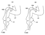
- FIG. 12 shows an operation explanatory diagram when the insertion portion 11 of the endoscope 2 ⁇ / b> B according to the present embodiment is inserted into the large intestine 61.
- movement at the time of inserting from the splenic curve 62 to the transverse colon 63 side is substantially the same as 1st Embodiment, it demonstrates in a site
- the state of FIG. 12A shows a state where the first bending portion 16A is inserted from the vicinity of the rectum to the sigmoid colon 67 side, and the first bending portion 16A is driven to bend in the first bending drive direction.
- a state in which the bending boundary 72 of one bending driving range 73 is reached is shown.
- the CPU 5a determines the first bending drive direction that exceeds the bending boundary 72
- the second bending portion 16B is held with the first bending portion 16A holding the bending driving state of the bending boundary 72. Drive the curve.
- the distal end side of the insertion portion 11 is as shown in FIG. 12B, and smooth insertion is facilitated.
- the bending drive range of the first bending portion 16A is not restricted as in the present embodiment, the bending angle of the first bending portion 16A is (with a small radius of curvature) as shown in FIG. It may be bent too much, making smooth insertion difficult. And this embodiment can eliminate that.
- Other operational effects are the same as those in the first embodiment. As described above, this embodiment can solve the problem of the first bending portion 16A being excessively curved and difficult to insert in addition to the effects of the first embodiment.
- FIG. 13 shows a configuration of a bending control device 40C in the present embodiment.
- This bending control device 40C has a configuration in which a bending activation switch 74 is further provided in the bending control device 40B in the second embodiment shown in FIG. Then, the setting unit 71 and the setting switch 71a are removed.
- the bending control unit 5 when the first bending portion 16 ⁇ / b> A exceeds the bending boundary 72, the bending control unit 5 holds the first bending portion 16 ⁇ / b> A on the bending boundary 72 and maintains the second bending.
- the part 16B was controlled to be driven to bend.
- the bending controller 5 drives the second bending portion 16B in the first bending driving direction with respect to the first bending portion 16A only during the period when the bending activation switch 74 is ON. Take control.
- the bending driving amount for the second bending portion 16B may be adjusted according to the operation of a lever or the like that can be input with an analog amount.
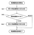
- the bending driving process in the automatic bending mode in the present embodiment will be described with reference to FIG.
- the CPU 5a determines the bending driving direction with respect to the first bending portion 16A as the first bending driving direction as in the first embodiment. Then, the CPU 5a controls the first bending drive mechanism 50A, and the first bending drive mechanism 50A drives the first bending portion 16A to bend in the first bending drive direction.
- the CPU 5a determines whether or not the bending activation switch is turned on.
- the CPU 5a holds the first bending portion 16A in the bending driving state immediately before the bending activation switch is turned on, and the first and subsequent times thereafter.
- the bending driving direction with respect to the bending portion 16A is determined as the second bending driving direction with respect to the second bending portion 16B.
- the CPU 5a controls the second bending drive mechanism 50B, and the second bending drive mechanism 50B drives the second bending portion 16B to bend in the second bending drive direction.
- the process of FIG. 13 ends. Also, if the determination result in step S42 is not applicable, the process in FIG. 13 is terminated.
- This embodiment has an effect similar to that of the second embodiment.
- the bending activation switch is turned on. By doing so, the bending drive can be performed without the curvature radius becoming too small.
- Other effects are the same as those of the first embodiment.
- a configuration having the functions of the second embodiment and the third embodiment may be used.
- the setting unit 71 and the setting switch 71 a may be provided, and a selection switch for selecting (switching) the function between the second embodiment and the third embodiment may be provided. In this case, it has the effect of 2nd Embodiment and 3rd Embodiment.
- FIG. 15 is an operation explanatory diagram according to the second modification.
- FIG. 15A shows a bending state when the bending activation switch 74 is turned on.
- the tip portion direction of the tip portion 15 is, for example, the right direction.
- the CPU 5a of the bending control unit 5 enters the bending state shown in FIG. 15C through the intermediate stage shown in FIG. 15B, and ends the operation of the second modification. According to this modification, the bending state of the bending portions 16A and 16B can be changed while the tip portion direction of the tip portion 15 is maintained.
- FIG. 16 shows a configuration of a bending control device 40D in the present embodiment.
- the bending control device 40D further includes an adjusting unit 75 that adjusts (sets) a driving ratio when the first bending portion 16A and the second bending portion 16B are simultaneously driven to be bent in the configuration of FIG.
- the adjustment unit 75 is realized by the processing function of the CPU 5a.
- the drive ratio can be selected by a selection operation using the switch 75a.
- the bending activation switch 74 when the bending activation switch 74 is OFF, the same operation as that of the third embodiment is performed.
- the bending activation switch 74 is ON, the adjusting unit 75 by the CPU 5a simultaneously drives the first bending unit 16A and the second bending unit 16B to be bent at the drive ratio selected by the switch 75a.
- the drive ratio by the switch 75a is set to a drive ratio of 1 as a default value.
- the operator can adjust the instruction value of the drive ratio when the first bending portion 16A and the second bending portion 16B are driven to be bent by the adjustment unit 75.
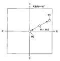
- FIG. 17 is an explanatory diagram of the contents of control by the CPU 5a of the bending control unit 5 in the present embodiment.
- FIG. 17 shows the current first bending position W1 and the current second bending position W2 with respect to the first bending portion 16A and the second bending portion 16B.
- the CPU 5a sets the target bending position, for example, at the center position on the line connecting the current first bending position W1 and the current second bending position W2.
- the first bending position Wt1 and the target second bending position Wt2 are determined.
- the case where the drive ratio is 1 is described.
- the CPU 5a performs control to drive the first bending portion 16A and the second bending portion 16B to the target first bending position Wt1 and the target second bending position Wt2, respectively.
- the positions of the target first bending position Wt1 and the target second bending position Wt2 can be changed.
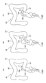
- the curved shape of the first curved portion 16A and the second curved portion 16B will be described as shown in FIGS. 18A and 18B.
- FIG. 18A when the bending drive is performed only by the first bending portion 16A, the first bending portion 16A may be excessively driven for bending. In this state, insertion into the deep side of the sigmoid colon 67 becomes difficult.
- the first bending portion 16A and the second bending portion 16B have the same bending radius (bending radius) as the target bending position (FIG. 18). It can be driven to bend as shown in B).
- the state shown in FIG. 18B is set, it becomes easy to insert the sigmoid colon 67 into the deep side.
- the first bending portion 16A and the second bending portion 16B are driven to be bent at the same time, and the drive ratio at that time can be variably set.
- bending driving suitable for the insertion site can be performed as compared with a case where bending driving is performed only by the first bending portion 16A.
- embodiments configured by partially combining the above-described embodiments belong to the present invention.
Abstract
内視鏡装置は、先端側に湾曲部が設けられた挿入部と、湾曲部を電気的に湾曲駆動する湾曲駆動部と、挿入部の先端側の挿入形状を検出する挿入形状検出部と、挿入部の先端側の屈曲情報に基づいて、屈曲した管状の体腔内に挿入された状態の挿入部の先端側が含まれる屈曲した屈曲平面を推定し、推定した屈曲平面の情報を利用して湾曲部を湾曲駆動する制御を行う湾曲制御部と、を具備する。
Description
本発明は、内視鏡の湾曲部を電気的に湾曲駆動する内視鏡装置及び湾曲駆動制御方法に関する。
挿入部の先端側に撮像手段と、湾曲自在の湾曲部を設けた内視鏡は体腔内の検査、診断等に広く用いられるようになっている。
また、大腸等の複雑に屈曲した体腔内に挿入部を円滑に挿入する場合には、熟練を要する場合がある。例えば、大腸内における横行結腸は、撓んでいるためにそのままの状態で深部側の肝湾曲側に挿入しずらいため、横行結腸のたわみを取り除き、直線化する挿入手技としての所謂、跳ね上げが一般に行われる。
しかし、内視鏡画像からどの方向に横行結腸が走行している面であるか等が分かりづらいため、湾曲させるべき方向を決定することが困難であると共に、円滑な挿入を行うことが困難であった。
また、大腸等の複雑に屈曲した体腔内に挿入部を円滑に挿入する場合には、熟練を要する場合がある。例えば、大腸内における横行結腸は、撓んでいるためにそのままの状態で深部側の肝湾曲側に挿入しずらいため、横行結腸のたわみを取り除き、直線化する挿入手技としての所謂、跳ね上げが一般に行われる。
しかし、内視鏡画像からどの方向に横行結腸が走行している面であるか等が分かりづらいため、湾曲させるべき方向を決定することが困難であると共に、円滑な挿入を行うことが困難であった。
一方、例えば特開2006-116289号公報においては、挿入部を円滑に挿入し易くするために、挿入部の先端部に設けた撮像手段により得られた撮像画像に加えて、挿入部の長手方向に配置した位置検出コイルの位置検出に基づいて算出した挿入部の先端側の挿入形状(屈曲形状)の情報を利用する内視鏡装置が開示されている。
しかしながら、上記公報の従来例による挿入形状のみでは、例えば大腸内における横行結腸におけるたわみを取り除くような適切な方向に精度良く湾曲駆動するように跳ね上げる湾曲制御ができない。
このため、挿入部の先端側の挿入形状から、横行結腸におけるたわみを取り除く方向に跳ね上げるように湾曲駆動する等、適切な方向に精度良く湾曲部を湾曲駆動することが望まれる。この場合、上記従来例における内視鏡画像を必要としないで、湾曲部を湾曲駆動することができると、より有効となる。
本発明は、上記問題点に鑑みてなされたものであり、挿入部の先端側の屈曲した挿入形状に基づいて湾曲部を適切な方向に精度良く湾曲駆動することができる内視鏡装置及び湾曲駆動制御方法を提供することを目的とする。
このため、挿入部の先端側の挿入形状から、横行結腸におけるたわみを取り除く方向に跳ね上げるように湾曲駆動する等、適切な方向に精度良く湾曲部を湾曲駆動することが望まれる。この場合、上記従来例における内視鏡画像を必要としないで、湾曲部を湾曲駆動することができると、より有効となる。
本発明は、上記問題点に鑑みてなされたものであり、挿入部の先端側の屈曲した挿入形状に基づいて湾曲部を適切な方向に精度良く湾曲駆動することができる内視鏡装置及び湾曲駆動制御方法を提供することを目的とする。
本発明の内視鏡装置は、先端側に湾曲自在の湾曲部が設けられた挿入部と、
前記湾曲部を電気的に湾曲駆動する湾曲駆動部と、
前記挿入部の先端側の挿入形状を検出する挿入形状検出部と、
前記挿入形状検出部による前記挿入部の先端側の挿入形状の情報に基づいて、屈曲した管状体腔内に挿入された状態の前記挿入部の先端側が含まれる屈曲した屈曲平面を推定し、推定した屈曲平面の情報を利用して前記湾曲部を湾曲駆動する制御を行う湾曲制御部と、
を具備することを特徴とする。
前記湾曲部を電気的に湾曲駆動する湾曲駆動部と、
前記挿入部の先端側の挿入形状を検出する挿入形状検出部と、
前記挿入形状検出部による前記挿入部の先端側の挿入形状の情報に基づいて、屈曲した管状体腔内に挿入された状態の前記挿入部の先端側が含まれる屈曲した屈曲平面を推定し、推定した屈曲平面の情報を利用して前記湾曲部を湾曲駆動する制御を行う湾曲制御部と、
を具備することを特徴とする。
本発明の湾曲駆動制御方法は、湾曲自在の湾曲部が設けられた挿入部の先端側が管状体腔内における屈曲した屈曲形状に沿って挿入された際の前記挿入部の先端側を含む屈曲平面を推定する屈曲平面推定ステップと、
前記挿入部の先端付近に、前記挿入部の先端側の軸方向を法線方向とした仮想平面を設定する仮想平面設定ステップと、
前記屈曲平面及び前記仮想平面との交差線に基づき、前記湾曲部を湾曲駆動する湾曲駆動方向を決定する湾曲駆動方向決定ステップと、
を具備することを特徴とする。
前記挿入部の先端付近に、前記挿入部の先端側の軸方向を法線方向とした仮想平面を設定する仮想平面設定ステップと、
前記屈曲平面及び前記仮想平面との交差線に基づき、前記湾曲部を湾曲駆動する湾曲駆動方向を決定する湾曲駆動方向決定ステップと、
を具備することを特徴とする。
以下、図面を参照して本発明の実施形態を説明する。
(第1の実施形態)
図1に示すように、本発明の第1の実施形態に係る内視鏡装置1は、体腔内等に挿入される内視鏡2と、この内視鏡2に照明光を供給する光源部3、内視鏡2に内蔵された撮像手段に対する信号処理を行う信号処理部4、内視鏡2の湾曲部の湾曲制御を行う湾曲制御部5等を内蔵したビデオプロセッサ6とを有する。
この内視鏡装置1は、さらに内視鏡2に設けられた位置検出用のソースコイルの位置検出を行うセンスコイルユニット7と、このセンスコイルユニット7からの検出信号により、内視鏡2の挿入部11の挿入形状を検出し、その画像を生成する挿入形状検出装置8と、撮像手段により撮像した内視鏡画像と挿入形状検出装置8による挿入形状検出画像とをそれぞれ表示するモニタ10A及び10Bとを有する。
内視鏡2は、体腔内に挿入される細長の挿入部11と、この挿入部11の後端に設けられた操作部12と、この操作部12から延出されたユニバーサルコード13とを有し、このユニバーサルコード13の後端のコネクタ14は、ビデオプロセッサ6に着脱自在に接続される。
また、挿入部11は、その先端に設けられた硬質の先端部15と、この先端部15の後端に隣接して湾曲自在に設けられた湾曲部16と、この湾曲部16の後端から操作部12の前端にまで延びる長尺の可撓性を有する可撓管部17とを有する。
操作部12には、前記湾曲部16を湾曲方向及び湾曲角度の指示操作を行う湾曲指示操作手段としての湾曲用ジョイスティック18と、自動湾曲(自動挿入)モードと手動湾曲(手動挿入)モードの選択を行うモード選択スイッチ19と、静止画の表示指示などを行うスコープスイッチ20とが設けてある。
また、挿入部11は、その先端に設けられた硬質の先端部15と、この先端部15の後端に隣接して湾曲自在に設けられた湾曲部16と、この湾曲部16の後端から操作部12の前端にまで延びる長尺の可撓性を有する可撓管部17とを有する。
操作部12には、前記湾曲部16を湾曲方向及び湾曲角度の指示操作を行う湾曲指示操作手段としての湾曲用ジョイスティック18と、自動湾曲(自動挿入)モードと手動湾曲(手動挿入)モードの選択を行うモード選択スイッチ19と、静止画の表示指示などを行うスコープスイッチ20とが設けてある。
なお、自動湾曲モードが選択された場合においては、湾曲制御部5は、湾曲部16の湾曲駆動方向を自動的に決定し、術者は単に挿入部11を深部側に押し込む作業を行う。手動湾曲モードが選択された場合においては、術者がジョイスティック18を操作して湾曲部16の湾曲駆動方向の指示操作し、湾曲駆動部5は指示操作に従った湾曲駆動方向を、湾曲部16に対する湾曲駆動方向として決定する。そして、術者は、挿入部11を深部側に押し込む作業を行う。
この内視鏡2の挿入部11内等には、照明光を伝送するライトガイド21が挿通されており、このライトガイド21の後端は、コネクタ14から突出して入射端面となる。
この入射端面には、光源部3に内蔵されたランプ22による照明光が絞り23及び集光レンズ24を経て入射される。なお、ランプ22はランプ駆動回路25から供給されるランプ駆動電源により点灯して、照明光を発生する。
この内視鏡2の挿入部11内等には、照明光を伝送するライトガイド21が挿通されており、このライトガイド21の後端は、コネクタ14から突出して入射端面となる。
この入射端面には、光源部3に内蔵されたランプ22による照明光が絞り23及び集光レンズ24を経て入射される。なお、ランプ22はランプ駆動回路25から供給されるランプ駆動電源により点灯して、照明光を発生する。
また、絞り23は、絞り制御回路26により、照明光を通過する開口量(絞り量)が制御される。
ライトガイド21により伝送された照明光は、挿入部11の先端部15に固定されたライトガイド先端面からさらに照明窓に取り付けられた照明レンズ27(図2参照)を経て外部に出射され、体腔内の患部等の被写体を照明する。
図2に示すように先端部15には、(照明窓に隣接して)観察窓が設けてあり、この観察窓には、撮像ユニット31が取り付けられている。
この撮像ユニット31は、図示しないレンズ枠に取り付けられ、被写体の光学像を結像する対物レンズ32と、この対物レンズ32による結像位置にその撮像面が配置された撮像素子としての電荷結合素子(CCDと略記)33とを有する。
ライトガイド21により伝送された照明光は、挿入部11の先端部15に固定されたライトガイド先端面からさらに照明窓に取り付けられた照明レンズ27(図2参照)を経て外部に出射され、体腔内の患部等の被写体を照明する。
図2に示すように先端部15には、(照明窓に隣接して)観察窓が設けてあり、この観察窓には、撮像ユニット31が取り付けられている。
この撮像ユニット31は、図示しないレンズ枠に取り付けられ、被写体の光学像を結像する対物レンズ32と、この対物レンズ32による結像位置にその撮像面が配置された撮像素子としての電荷結合素子(CCDと略記)33とを有する。
そして、CCD33に接続されたケーブルは、挿入部11内等を挿通され、その後端側は図1に示すようにコネクタ14の電気接点を経て信号処理部4を構成するCCD駆動回路36及び映像処理回路37に接続される。
CCD駆動回路36は、CCD駆動信号を発生し、このCCD駆動信号をCCD33に印加する。CCD33は、CCD駆動信号の印加により、撮像面に結像された光学像を光電変換して、CCD出力信号として出力する。
このCCD出力信号は、映像処理回路37に入力され、映像処理回路37は、CCD33の撮像面の光学像を内視鏡画像として表示する映像信号を生成し、モニタ10Aに出力することにより、モニタ10Aの表示画面には内視鏡画像が表示される。
CCD駆動回路36は、CCD駆動信号を発生し、このCCD駆動信号をCCD33に印加する。CCD33は、CCD駆動信号の印加により、撮像面に結像された光学像を光電変換して、CCD出力信号として出力する。
このCCD出力信号は、映像処理回路37に入力され、映像処理回路37は、CCD33の撮像面の光学像を内視鏡画像として表示する映像信号を生成し、モニタ10Aに出力することにより、モニタ10Aの表示画面には内視鏡画像が表示される。
なお、CCD33は、先端部15内における湾曲部16の湾曲方向と所定の関係を持つように配置されている。具体的には、CCD33の撮像面の上方向が湾曲部16の上下左右の湾曲方向における上方向としている。
また、映像信号は、絞り制御回路26に入力され、この絞り制御回路26はこの映像信号の輝度信号成分を所定周期で積分する等して平均の明るさを算出する。この平均の明るさの信号から適切な明るさに相当する基準値を引き算した差分の信号を絞り制御信号として絞り23の開口量を調整する。そして、絞り23を通過する照明光量が基準値となるように自動調光する。
また、映像処理回路37は、内視鏡画像中における暗部の有無を、画像処理により検出する暗部検出回路37aを有する。この暗部検出回路37aによる暗部の有無の検出(判定)情報は、湾曲制御部5に送られる。
また、映像信号は、絞り制御回路26に入力され、この絞り制御回路26はこの映像信号の輝度信号成分を所定周期で積分する等して平均の明るさを算出する。この平均の明るさの信号から適切な明るさに相当する基準値を引き算した差分の信号を絞り制御信号として絞り23の開口量を調整する。そして、絞り23を通過する照明光量が基準値となるように自動調光する。
また、映像処理回路37は、内視鏡画像中における暗部の有無を、画像処理により検出する暗部検出回路37aを有する。この暗部検出回路37aによる暗部の有無の検出(判定)情報は、湾曲制御部5に送られる。
湾曲制御部5は、挿入部11を自動湾曲する自動湾曲モードが選択されている場合においては、通常は暗部を挿入する場合の目標位置として、先端部15が暗部の方向を目指す(指向する)ように湾曲部16の湾曲駆動方向及び湾曲量(湾曲角)を制御する。
また、手動挿入モードにおいては、術者は、暗部を挿入する場合の目標位置として、先端部15が暗部の方向を目指すようにジョイスティック18を操作して、湾曲部16の湾曲駆動方向及び湾曲量(湾曲角)を設定する。
挿入部11内には図示しない処置具用チャンネルが設けてあり、この処置具用チャンネルの後端側は、操作部12の前端付近に設けられた処置具挿入口39と連通している。
また、手動挿入モードにおいては、術者は、暗部を挿入する場合の目標位置として、先端部15が暗部の方向を目指すようにジョイスティック18を操作して、湾曲部16の湾曲駆動方向及び湾曲量(湾曲角)を設定する。
挿入部11内には図示しない処置具用チャンネルが設けてあり、この処置具用チャンネルの後端側は、操作部12の前端付近に設けられた処置具挿入口39と連通している。
また、挿入部11の先端部15の後端に隣接して湾曲部16が設けてあり、ビデオプロセッサ6内部に設けた湾曲制御部5は、図2に示すような電動方式の湾曲駆動機構50の制御を行う構成となっている。図2の湾曲駆動機構50及び湾曲制御部5により、湾曲制御装置40が構成される。
湾曲部16を構成する複数の湾曲駒51は、湾曲部16の長手方向にそれぞれ隣接する部分がリベット52により回動自在に連結されている。
各湾曲駒51は、リベット52を設ける位置によって湾曲する方向が定まり、リベット52は、左右位置と上下位置に交互または適宜周期毎に配置され、湾曲部16は上下方向、左右方向の他に任意の方向に湾曲可能になっている。
湾曲部16を構成する複数の湾曲駒51は、湾曲部16の長手方向にそれぞれ隣接する部分がリベット52により回動自在に連結されている。
各湾曲駒51は、リベット52を設ける位置によって湾曲する方向が定まり、リベット52は、左右位置と上下位置に交互または適宜周期毎に配置され、湾曲部16は上下方向、左右方向の他に任意の方向に湾曲可能になっている。
なお、図2においては、簡略化して上下方向に湾曲させるリベット52のみで示している。また、挿入部11内には、上下方向と左右方向に湾曲させるアングルワイヤ(湾曲ワイヤ)53u、53dと53l、53rとが挿通され、これらのアングルワイヤ53u、53dと53l、53rの先端は先端部15に固着されている。
また、アングルワイヤ53u、53dと53l、53rの後端は、操作部12内に配置された上下湾曲用プーリ54aと、左右湾曲用プーリ54bに固定されている。
プーリ54a,54bは、湾曲部16を電気的に湾曲駆動する湾曲駆動手段を構成する電動モータ55a,55bにより正逆自在に回転される。電動モータ55a,55bは、モータ駆動部56によるモータ駆動信号により駆動される。モータ駆動部56は、湾曲制御部5により制御される。
また、アングルワイヤ53u、53dと53l、53rの後端は、操作部12内に配置された上下湾曲用プーリ54aと、左右湾曲用プーリ54bに固定されている。
プーリ54a,54bは、湾曲部16を電気的に湾曲駆動する湾曲駆動手段を構成する電動モータ55a,55bにより正逆自在に回転される。電動モータ55a,55bは、モータ駆動部56によるモータ駆動信号により駆動される。モータ駆動部56は、湾曲制御部5により制御される。
なお、図1においては湾曲制御部5を、ビデオプロセッサ6の内部に設けた構成例で示しているが、湾曲制御部5を、操作部12内部など内視鏡2の内部に設けるようにしても良い。
モータ駆動部56によるモータ駆動信号で駆動される電動モータ55a,55bは、プーリ54a,54bを回転し、プーリ54a,54bの回転によりアングルワイヤ53u、53d、53l、53rを牽引させて湾曲部16を湾曲駆動する。
プーリ54a,54bを回転させた場合、プーリ54a,54bの回転角に対応してアングルワイヤ53u、53d、53l、53rの牽引量が決まると共に、牽引量に対応して湾曲部16は湾曲する。従って、電動モータ55a,55b又はプーリ54a,54bの回転角又はアングルワイヤ53u、53d、53l、53rの牽引量(移動量)を検出することにより、湾曲部16の湾曲角を検出することができる。
モータ駆動部56によるモータ駆動信号で駆動される電動モータ55a,55bは、プーリ54a,54bを回転し、プーリ54a,54bの回転によりアングルワイヤ53u、53d、53l、53rを牽引させて湾曲部16を湾曲駆動する。
プーリ54a,54bを回転させた場合、プーリ54a,54bの回転角に対応してアングルワイヤ53u、53d、53l、53rの牽引量が決まると共に、牽引量に対応して湾曲部16は湾曲する。従って、電動モータ55a,55b又はプーリ54a,54bの回転角又はアングルワイヤ53u、53d、53l、53rの牽引量(移動量)を検出することにより、湾曲部16の湾曲角を検出することができる。
本実施形態においては、例えば電動モータ55a,55bのシャフト部に取り付けられているロータリエンコーダ(以下、エンコーダと略記)57a,57bによって、プーリ54a、54bの回転角を介して湾曲部16の湾曲角を検出する構成にしている。
つまり、エンコーダ57a,57bの出力信号を基に、プーリ54a、54bの回転角、換言するとプーリ54a、54bの回転角に対応する湾曲部16の湾曲角を検出することができるようになっている。従って、エンコーダ57a,57bは、湾曲部16の湾曲形状を検出する湾曲形状検出手段を形成する。
エンコーダ57a,57bの出力信号に基づくプーリ角又は湾曲角の検出信号(検出値)は、モータ駆動部56に入力される。このモータ駆動部56は、湾曲指示操作手段としてのジョイスティック18による湾曲駆動方向及び湾曲角の指示値が湾曲制御部5を介して入力される。
つまり、エンコーダ57a,57bの出力信号を基に、プーリ54a、54bの回転角、換言するとプーリ54a、54bの回転角に対応する湾曲部16の湾曲角を検出することができるようになっている。従って、エンコーダ57a,57bは、湾曲部16の湾曲形状を検出する湾曲形状検出手段を形成する。
エンコーダ57a,57bの出力信号に基づくプーリ角又は湾曲角の検出信号(検出値)は、モータ駆動部56に入力される。このモータ駆動部56は、湾曲指示操作手段としてのジョイスティック18による湾曲駆動方向及び湾曲角の指示値が湾曲制御部5を介して入力される。
そして、このモータ駆動部56は、指示値に対して、エンコーダ57a,57bによる検出値が追従(一致)するように電動モータ55a、55bを回転駆動させる。
湾曲制御部5は、湾曲指示操作手段による指示値をモータ駆動部56に与え、モータ駆動部56は、湾曲角の検出値が指示値となるように電動モータ55a、55bを回転駆動して湾曲部16を指示された所定の湾曲角度まで湾曲させるようになっている。
操作部12に設けられたジョイスティック18によって術者は、上下、左右の任意の湾曲方向に傾動する操作を行うことにより、傾動した方向が湾曲駆動方向の指示値になると共に、その傾動角が湾曲角の指示値となる。
湾曲制御部5は、湾曲指示操作手段による指示値をモータ駆動部56に与え、モータ駆動部56は、湾曲角の検出値が指示値となるように電動モータ55a、55bを回転駆動して湾曲部16を指示された所定の湾曲角度まで湾曲させるようになっている。
操作部12に設けられたジョイスティック18によって術者は、上下、左右の任意の湾曲方向に傾動する操作を行うことにより、傾動した方向が湾曲駆動方向の指示値になると共に、その傾動角が湾曲角の指示値となる。
術者がジョイスティック18を上下、左右の任意の方向に傾動する指示操作を行うことにより、傾動した方向に対応して上下方向ジョイスティックモータ58a及び左右方向ジョイスティックモータ58bが回転する。
その回転角は、エンコーダ59a,59bが検出し、エンコーダ59a,59bの検出信号は、湾曲制御部5に湾曲駆動方向及び湾曲角の指示値として入力される。なお、ジョイスティックモータ58a、58bは、湾曲制御部5により制御されると共に、エンコーダ59a,59bの検出信号も湾曲制御部5に入力される。
そして、湾曲制御部5は、エンコーダ59a,59bの検出信号としての湾曲駆動方向及び湾曲角の指示値をモータ駆動部56に出力し、その動作を制御する。
その回転角は、エンコーダ59a,59bが検出し、エンコーダ59a,59bの検出信号は、湾曲制御部5に湾曲駆動方向及び湾曲角の指示値として入力される。なお、ジョイスティックモータ58a、58bは、湾曲制御部5により制御されると共に、エンコーダ59a,59bの検出信号も湾曲制御部5に入力される。
そして、湾曲制御部5は、エンコーダ59a,59bの検出信号としての湾曲駆動方向及び湾曲角の指示値をモータ駆動部56に出力し、その動作を制御する。
また、挿入部11内には、その長手方向に沿ってソースコイル41が例えば所定間隔で配置されており、ソースコイル41に接続された信号線は、図1に示すようにコネクタ14の電気接点を経てビデオプロセッサ6内に設けたソースコイル駆動回路43と接続されている。
このソースコイル駆動回路43は、信号線を経て各ソースコイル41に交流の駆動信号を順次印加し、各ソースコイル41の周囲に交流磁場を発生する。
また、挿入部11が挿入される図示しない患者が横たわるベッドの周辺部などにおける所定位置には、図1に示すように複数のセンスコイル44からなるセンスコイルユニット7が配置され、複数のセンスコイル44により、挿入部11内に配置されたソースコイル41により発生される磁場を検出する。
このソースコイル駆動回路43は、信号線を経て各ソースコイル41に交流の駆動信号を順次印加し、各ソースコイル41の周囲に交流磁場を発生する。
また、挿入部11が挿入される図示しない患者が横たわるベッドの周辺部などにおける所定位置には、図1に示すように複数のセンスコイル44からなるセンスコイルユニット7が配置され、複数のセンスコイル44により、挿入部11内に配置されたソースコイル41により発生される磁場を検出する。
そして、センスコイル44による検出信号は、挿入形状検出装置8内のアンプ45により増幅された後、ソースコイル位置算出回路46に入力され、このソースコイル位置算出回路46により、センスコイル44により検出された信号における振幅値及び位相値から各ソースコイル41の位置を算出する。
このソースコイル位置算出回路46により算出された位置情報は、挿入形状算出回路47に入力される。この挿入形状算出回路47は、算出された各ソースコイル41の位置を連結した形状から体腔内に挿入される挿入部11の(屈曲した屈曲形状等の)挿入形状を検出し、検出した挿入形状をモデル化して挿入形状画像信号を生成する。
つまり、挿入形状算出回路47は、少なくとも挿入部11の先端側の屈曲形状の場合を含む挿入形状を検出する挿入形状検出部47aの機能を持つ。
このソースコイル位置算出回路46により算出された位置情報は、挿入形状算出回路47に入力される。この挿入形状算出回路47は、算出された各ソースコイル41の位置を連結した形状から体腔内に挿入される挿入部11の(屈曲した屈曲形状等の)挿入形状を検出し、検出した挿入形状をモデル化して挿入形状画像信号を生成する。
つまり、挿入形状算出回路47は、少なくとも挿入部11の先端側の屈曲形状の場合を含む挿入形状を検出する挿入形状検出部47aの機能を持つ。
挿入形状算出回路47により生成された挿入形状画像信号は、モニタ10Bに入力され、その表示画面に挿入部15の先端側の屈曲した場合等の挿入形状画像が表示される。
また、挿入形状算出回路47により算出された挿入部11の先端側の屈曲形状の場合を含む挿入形状の座標の情報は、湾曲制御部5により取得される。後述するように湾曲制御部5は、湾曲部16を湾曲駆動する制御を行う場合、特に挿入部11の先端側の屈曲した状態における(挿入形状の座標の情報としての)屈曲座標の情報を利用する。
なお、図2に示すように、先端部15内にも、ソースコイル41が取り付けてあり、ソースコイル位置算出回路46は、先端部15に取り付けた複数のソースコイル41の位置から先端部15の位置の他に、先端部15の周方向における上下、左右などの方向における特定の方向を算出する。先端部15内では、複数のソースコイル41が、先端部15の周方向を検出できるように、直線から外れた配置関係で配置されている。
先端部15内の複数のソースコイル41の配置により、先端部15の位置及び長手方向(先端部方向とも言う)の他に、先端部15の軸周りの基準方位を検出可能となる。
この先端部15内にはCCD33が固定された状態で配置されており、その撮像面の上方向(これは湾曲の下方向から上方向に向く時計の12時方向と一致)も検出可能になる。つまり、ソースコイル位置算出回路46は、先端部15の位置及びその基準方位を検出する位置・方位検出部46aの機能を有する。なお、位置・方位検出部46aは、湾曲部16の基準方位を検出する方位検出手段の機能を持つ。
そして、ソースコイル位置算出回路46は、先端部15の位置及び基準方位の情報を湾曲制御部5に出力する。
この先端部15内にはCCD33が固定された状態で配置されており、その撮像面の上方向(これは湾曲の下方向から上方向に向く時計の12時方向と一致)も検出可能になる。つまり、ソースコイル位置算出回路46は、先端部15の位置及びその基準方位を検出する位置・方位検出部46aの機能を有する。なお、位置・方位検出部46aは、湾曲部16の基準方位を検出する方位検出手段の機能を持つ。
そして、ソースコイル位置算出回路46は、先端部15の位置及び基準方位の情報を湾曲制御部5に出力する。
湾曲制御部5は、例えばCPU5aにより構成され、CPU5aは、入力された先端部15の位置及び基準方位の情報を利用して、湾曲部16を湾曲駆動する制御を行う。
また、本実施形態における湾曲制御部5は、体腔内における先端部15の位置が所定領域に達したか否かを判定する。その判定のために、湾曲制御部5は、先端部15が体腔内の挿入口の位置にセットされた位置から体腔内部に挿入された先端部15の位置までの挿入形状から挿入長を検出する。
例えば、先端部15が肛門の位置にセットされた場合における先端部15内部に配置されているソースコイル41の位置を記憶しておくことにより、先端部15が大腸内部に挿入された挿入長を検出することが可能になる。
また、本実施形態における湾曲制御部5は、体腔内における先端部15の位置が所定領域に達したか否かを判定する。その判定のために、湾曲制御部5は、先端部15が体腔内の挿入口の位置にセットされた位置から体腔内部に挿入された先端部15の位置までの挿入形状から挿入長を検出する。
例えば、先端部15が肛門の位置にセットされた場合における先端部15内部に配置されているソースコイル41の位置を記憶しておくことにより、先端部15が大腸内部に挿入された挿入長を検出することが可能になる。
また、本実施形態においては、湾曲制御手段としての湾曲制御部5は、管状体腔内としての大腸内における横行結腸の深部側に円滑に挿入するため、跳ね上げを行うのに適した平面(後述する屈曲平面)を推定して、湾曲部16を湾曲駆動する制御を行う。
より具体的には、湾曲制御部5を構成するCPU5aは、脾湾曲を経て撓んだ横行結腸内に挿入された挿入部11における湾曲部16ないしは可撓管部17部分の屈曲した平面を、屈曲平面として推定(生成)する屈曲平面推定部5bの機能を持つ。また、CPU5aは、上記屈曲平面(より広義には、屈曲平面に平行な平面)に沿って湾曲部16を湾曲する湾曲方向を決定するために、先端部15の位置において、その先端部15の先端部方向を法線方向とする仮想平面を一時的に設定する仮想平面設定部5cの機能を持つ。
より具体的には、湾曲制御部5を構成するCPU5aは、脾湾曲を経て撓んだ横行結腸内に挿入された挿入部11における湾曲部16ないしは可撓管部17部分の屈曲した平面を、屈曲平面として推定(生成)する屈曲平面推定部5bの機能を持つ。また、CPU5aは、上記屈曲平面(より広義には、屈曲平面に平行な平面)に沿って湾曲部16を湾曲する湾曲方向を決定するために、先端部15の位置において、その先端部15の先端部方向を法線方向とする仮想平面を一時的に設定する仮想平面設定部5cの機能を持つ。
また、CPU5aは、後述するように上記屈曲平面とこの仮想平面との交差線を求めると共に、先端部15又は湾曲部16の特定の湾曲方向を基準方位として、この基準方位と交差線のなす角度を算出する処理を行う角度算出部5dの機能を持つ。そして、CPU5aは、その交差線に沿った方向を湾曲駆動方向に決定する湾曲駆動方向決定部5eの機能を持つ。
次に本実施形態による作用を図3のフローチャートを参照して説明する。
図1に示す内視鏡装置1の電源が投入されると、内視鏡装置1の各部が動作する。術者は、図3のステップS1に示すように内視鏡2の挿入部11の先端側を内視鏡検査を行う検査対象となる大腸内に肛門から挿入する。
次に本実施形態による作用を図3のフローチャートを参照して説明する。
図1に示す内視鏡装置1の電源が投入されると、内視鏡装置1の各部が動作する。術者は、図3のステップS1に示すように内視鏡2の挿入部11の先端側を内視鏡検査を行う検査対象となる大腸内に肛門から挿入する。
大腸内部への挿入を開始すると、湾曲制御部5のCPU5aは、ステップS2に示すように挿入形状検出装置8による挿入部11の挿入形状の情報を取得する。また、次のステップS3においてCPU5aは、湾曲部16の湾曲座標の情報を取得する。
また、次のステップS4においてCPU5aは、暗部検出回路37aによる内視鏡画像からの暗部の情報を取得する。そして、ステップS5に示すように暗部の位置を挿入目標方向として、挿入部11の先端側を大腸の深部側に挿入する。
また、ステップS6に示すようにCPU5aは、挿入長をモニタして、先端部15が所定の領域としての脾湾曲を通過して横行結腸内に達したか否かの判定を行う。この場合、大腸における脾湾曲の部位は急峻に屈曲しているので、CPU5aは挿入長だけでなく、湾曲部16の湾曲角度の情報をモニタして所定角度以上の湾曲の有無の情報を利用して、所定の領域に達したか否かを判定しても良い。
また、ステップS6に示すようにCPU5aは、挿入長をモニタして、先端部15が所定の領域としての脾湾曲を通過して横行結腸内に達したか否かの判定を行う。この場合、大腸における脾湾曲の部位は急峻に屈曲しているので、CPU5aは挿入長だけでなく、湾曲部16の湾曲角度の情報をモニタして所定角度以上の湾曲の有無の情報を利用して、所定の領域に達したか否かを判定しても良い。
CPU5aは、所定領域に達していないと判定した場合には、ステップS2の処理に戻り、ステップS2~S6の処理を繰り返す。
一方、先端部15が脾湾曲を通過して横行結腸内に達した場合(つまり、挿入部11の先端側が脾湾曲で屈曲している状態となった場合)には、CPU5aはステップS7の湾曲駆動方向決定処理を行い、次のステップS8において決定された湾曲駆動方向における湾曲駆動目標位置を決定して湾曲部16を湾曲駆動する制御を行う。つまり、CPU5aは、挿入部11の先端側が所定領域に達した場合には、後述する図4及び図6にて説明する湾曲駆動制御方法により湾曲部16を湾曲駆動する制御を行う。
一方、先端部15が脾湾曲を通過して横行結腸内に達した場合(つまり、挿入部11の先端側が脾湾曲で屈曲している状態となった場合)には、CPU5aはステップS7の湾曲駆動方向決定処理を行い、次のステップS8において決定された湾曲駆動方向における湾曲駆動目標位置を決定して湾曲部16を湾曲駆動する制御を行う。つまり、CPU5aは、挿入部11の先端側が所定領域に達した場合には、後述する図4及び図6にて説明する湾曲駆動制御方法により湾曲部16を湾曲駆動する制御を行う。
次のステップS9において湾曲駆動目標位置まで湾曲部16を湾曲駆動した状態にして横行結腸の深部側に先端部側を挿入する。
そして、先端部15が肝湾曲を経て上行結腸又は盲腸付近に達するまで挿入して、この挿入部11を挿入する手技を終了する。そして、術者は例えば、挿入部11を引き抜きながら、内視鏡検査を行う。
そして、先端部15が肝湾曲を経て上行結腸又は盲腸付近に達するまで挿入して、この挿入部11を挿入する手技を終了する。そして、術者は例えば、挿入部11を引き抜きながら、内視鏡検査を行う。
図4はステップS7の湾曲駆動方向決定処理の手順を示す。以下の説明から分かるように、実質的な湾曲駆動方向決定処理は、図4における枠Fで囲ったステップS16-S18である。そして、ステップS16-S18が湾曲部16を湾曲駆動する駆動駆動制御方法の主要な処理手順となる。
湾曲駆動方向決定処理が開始すると、最初のステップS11においてCPU5aは、挿入形状検出装置8による挿入部11の挿入形状の情報を取得する。また、次のステップS12においてCPU5aは、湾曲部16の湾曲座標の情報を取得する。
なお、ステップS11及びS12は、図3のステップS2及びS3と同じ処理であり、挿入部11の先端側の状態が変化していない又は変化量が小さい場合には、ステップS2及びS3の情報を流用しても良い。
湾曲駆動方向決定処理が開始すると、最初のステップS11においてCPU5aは、挿入形状検出装置8による挿入部11の挿入形状の情報を取得する。また、次のステップS12においてCPU5aは、湾曲部16の湾曲座標の情報を取得する。
なお、ステップS11及びS12は、図3のステップS2及びS3と同じ処理であり、挿入部11の先端側の状態が変化していない又は変化量が小さい場合には、ステップS2及びS3の情報を流用しても良い。
次のステップS13においてCPU5aは、自動湾曲モードであるか否かの判定を行う。自動湾曲モードでない(つまり、手動湾曲モードの)場合には、ステップS14においてCPU5aは、ジョイスティック18による湾曲指示に対して、その湾曲指示に対応した情報をエンコーダ59a、59bを介して取得する。
そして、次のステップS15においてCPU5aは、ジョイスティック18による湾曲指示に従って湾曲駆動方向を決定し、ステップS19の処理に進む。
一方、ステップS13において自動湾曲モードが選択されている判定結果の場合には、自動湾曲駆動処理の1形態としての実質的な湾曲駆動方向決定処理を構成するステップS16の処理に進み、このステップS16においてCPU5aは、屈曲平面の推定(生成)処理を行う。
そして、次のステップS15においてCPU5aは、ジョイスティック18による湾曲指示に従って湾曲駆動方向を決定し、ステップS19の処理に進む。
一方、ステップS13において自動湾曲モードが選択されている判定結果の場合には、自動湾曲駆動処理の1形態としての実質的な湾曲駆動方向決定処理を構成するステップS16の処理に進み、このステップS16においてCPU5aは、屈曲平面の推定(生成)処理を行う。
後述するようにして、この屈曲平面を推定した後、次のステップS17においてCPU5aは、仮想平面の生成(設定)処理を行う。さらに次のステップS18においてCPU5aは、屈曲平面と仮想平面の交差線に基づく湾曲駆動方向の決定処理を行い、次のステップS19の湾曲駆動目標位置の決定処理に進む。
次に図5及び図6を参照して、上記湾曲駆動方向決定処理における屈曲平面等を推定する詳細な処理手順を説明する。図5は内視鏡2の挿入部11の先端側が所定領域としての大腸61における脾湾曲62を経て横行結腸63側まで挿入された状態を示す。
このように挿入部11の先端側が所定領域内に挿入された状態において、図6のステップS21に示すように、湾曲制御部5のCPU5aは、(挿入部11の先端側の湾曲部16ないしは可撓管部17の)挿入形状部分の位置情報のうち、曲率半径が最も小さい位置P3を特定する。
次に図5及び図6を参照して、上記湾曲駆動方向決定処理における屈曲平面等を推定する詳細な処理手順を説明する。図5は内視鏡2の挿入部11の先端側が所定領域としての大腸61における脾湾曲62を経て横行結腸63側まで挿入された状態を示す。
このように挿入部11の先端側が所定領域内に挿入された状態において、図6のステップS21に示すように、湾曲制御部5のCPU5aは、(挿入部11の先端側の湾曲部16ないしは可撓管部17の)挿入形状部分の位置情報のうち、曲率半径が最も小さい位置P3を特定する。
図5に示すように挿入部11の屈曲角度は、(急峻に屈曲している)脾湾曲62部分において最も大きくなるため、曲率半径が最も小さい位置P3を特定することにより脾湾曲62内側での屈曲した挿入部11における基準位置を特定することができる。
次のステップS22においてCPU5aは、屈曲した挿入部11の挿入形状部分における曲率半径が最も小さい位置P3を基準位置として、その位置P3の前後(つまり、挿入部11の長手方向に関しての前後)に適宜の間隔で隣接する2点の位置P1、P2及びP4,P5の座標を取得して、計5点の座標を取得する。なお、図5のOは座標系の原点を示している。
この場合、挿入部11の長手方向に所定間隔で配置したソースコイル41の座標を利用しても良い。なお、5点は、1つの代表例であって、この数に限定されるものでない。
次のステップS22においてCPU5aは、屈曲した挿入部11の挿入形状部分における曲率半径が最も小さい位置P3を基準位置として、その位置P3の前後(つまり、挿入部11の長手方向に関しての前後)に適宜の間隔で隣接する2点の位置P1、P2及びP4,P5の座標を取得して、計5点の座標を取得する。なお、図5のOは座標系の原点を示している。
この場合、挿入部11の長手方向に所定間隔で配置したソースコイル41の座標を利用しても良い。なお、5点は、1つの代表例であって、この数に限定されるものでない。
次のステップS23においてCPU5aは、取得した5点の位置P1~P5の座標に対して主成分分析(PCA)を実施して、5点の座標分布に応じた、互いに直交する座標軸となる第1主成分方向Pc1、第2主成分方向Pc2、第3主成分方向Pc3を推定(導出)する。
この場合、第1主成分方向Pc1は、挿入部11上の5点の座標データの散らばり具合(分散)が最も大きくなる方向となり、第2主成分方向Pc2は、この第1主成分方向Pc1に直交し、次に分散が大きくなる方向となる。そして、第3主成分方向Pc3が、第1主成分方向Pc1及び第2主成分方向Pc2(を含む平面)に直交する方向となる。
この場合、第1主成分方向Pc1は、挿入部11上の5点の座標データの散らばり具合(分散)が最も大きくなる方向となり、第2主成分方向Pc2は、この第1主成分方向Pc1に直交し、次に分散が大きくなる方向となる。そして、第3主成分方向Pc3が、第1主成分方向Pc1及び第2主成分方向Pc2(を含む平面)に直交する方向となる。
図7Aは推定された第1主成分方向Pc1及び第2主成分方向Pc2を示し、該第1主成分方向Pc1及び第2主成分方向Pc2を含む平面が推定された屈曲平面64となる。
また、図7Bは推定された第3主成分方向Pc3を示し、この第3主成分方向Pc3が挿入部11の先端側部分が脾湾曲62で屈曲している状態のその屈曲した屈曲平面64に垂直な法線方向となる。換言すると、屈曲平面64のみを推定するのでなく、これに垂直な法線方向も推定することによって、より精度の高い屈曲平面64を推定することができる。
また、図7Bは推定された第3主成分方向Pc3を示し、この第3主成分方向Pc3が挿入部11の先端側部分が脾湾曲62で屈曲している状態のその屈曲した屈曲平面64に垂直な法線方向となる。換言すると、屈曲平面64のみを推定するのでなく、これに垂直な法線方向も推定することによって、より精度の高い屈曲平面64を推定することができる。
従って、ステップS21~S23が屈曲平面64を推定する屈曲平面推定処理となる。
次のステップS24においてCPU5aは、推定した屈曲平面64における挿入部11の基端側から先端側へと挿入部11の屈曲形状に沿ってトレースした場合における屈曲した挿入部11が脾湾曲62で、(この屈曲平面64に垂直な軸に対して)時計回り方向(右回り方向)、又は反時計回り方向(左回り方向)のいずれの方向に回転(屈曲)しているかの回転方向(屈曲方向)を調べる。そして、CPU5aは、その回転方向と逆方向を、湾曲駆動方向の目標方向と設定する。
次のステップS24においてCPU5aは、推定した屈曲平面64における挿入部11の基端側から先端側へと挿入部11の屈曲形状に沿ってトレースした場合における屈曲した挿入部11が脾湾曲62で、(この屈曲平面64に垂直な軸に対して)時計回り方向(右回り方向)、又は反時計回り方向(左回り方向)のいずれの方向に回転(屈曲)しているかの回転方向(屈曲方向)を調べる。そして、CPU5aは、その回転方向と逆方向を、湾曲駆動方向の目標方向と設定する。
この場合の回転方向又は逆の回転方向として、2つのベクトルの外積の符号により、右回り/左回りを区別する。具体的には、挿入部11の挿入形状に沿って、脾湾曲62を挟むようにその基端側に設定した第1のベクトルと、先端側に設定した第2のベクトルとの外積の符号により、湾曲駆動方向の目標方向とする。ベクトルの外積処理により、湾曲駆動方向の目標方向の設定(推定)を行う。
図5の屈曲した挿入形状の場合を左回りとすると、その逆の右回りとする方向を湾曲駆動方向の目標方向とする。
図5の屈曲した挿入形状の場合を左回りとすると、その逆の右回りとする方向を湾曲駆動方向の目標方向とする。
次のステップS25においてCPU5aは、図4のステップS17の仮想平面の設定を行う。このために、CPU5aは、先端部15の位置(図5においてC0)において、先端部方向(図5においてベクトルV)を法線方向とする仮想平面65を設定する。
この場合、湾曲の上方向(CCD33の撮像面の上方向に一致し、図5ではベクトルR)等の基準方位を、仮想平面65の基準方向に設定する。換言すると、仮想平面65における基準の方向を基準方位と一致又は所定の関係となるように対応付ける。
次のステップS26においてCPU5aは、この仮想平面65と(主成分分析を実施して推定した)屈曲平面64との交差線Lを算出する。
この場合、湾曲の上方向(CCD33の撮像面の上方向に一致し、図5ではベクトルR)等の基準方位を、仮想平面65の基準方向に設定する。換言すると、仮想平面65における基準の方向を基準方位と一致又は所定の関係となるように対応付ける。
次のステップS26においてCPU5aは、この仮想平面65と(主成分分析を実施して推定した)屈曲平面64との交差線Lを算出する。
図5の左側には、(湾曲部16又は撮像面の)上下、左右の方向に対応付けた状態での仮想平面65における交差線Lを示す。
次のステップS27においてCPU5aは、交差線Lと左右の方向とのなす角度θを湾曲駆動方向として算出(推定)する。
このようにして湾曲駆動方向として算出した次のステップS28においてCPU5aは、現在の湾曲位置から角度θの方向に湾曲部16を湾曲駆動させることにより、弛んだ状態の横行結腸63に対して、適切な跳ね上げを精度良く行うことができる。そして、図6の処理を終了する。
図8は、プーリ角による座標系における湾曲部16の現在の湾曲位置(湾曲駆動位置)W等を示す。CPU5aは、モータ駆動部56を介して電動モータ55a、55bを駆動制御し、電動モータ55a、55bは、現在の湾曲位置Wから上記角度θの方向に湾曲部16を湾曲駆動して、先端部15側により跳ね上げを行う。
上記弛んだ状態の横行結腸63を、先端部15側により跳ね上げることにより、横行結腸63を直線に近い状態に設定でき、術者は挿入部11の円滑な挿入がし易くなる。
このような作用を有する本実施形態によれば、弛んだ状態の横行結腸63を挿入部11の先端側が脾湾曲62を経て横行結腸63側に屈曲して挿入された屈曲形状の情報を利用して、その屈曲形状が載る屈曲平面64を精度良く推定することができる。
そして、推定したこの屈曲平面64上で屈曲している方向と逆方向に湾曲部16を湾曲駆動して横行結腸63を直線に近い状態に設定する跳ね上げを高精度にでき、挿入部11の円滑な挿入が行い易くなる。
なお、屈曲平面64上で湾曲部16を湾曲駆動する場合に限らず、屈曲平面64に平行な平面に沿って湾曲部16を湾曲駆動するようにしても良い。
また、本実施形態は、挿入部11の先端側を脾湾曲62から横行結腸63側に挿入した場合の跳ね上げを行う場合に限定されるものでなく、他の部位に挿入した場合に適用しても良い。また、本実施形態における屈曲平面64を推定する方法等は、挿入部11を屈曲した管状体腔内へ挿入した場合に広く適用できる。
(第2の実施形態)
次に本発明の第2の実施形態を説明する。第1の実施形態においては、内視鏡2の挿入部11には先端部15の後端に1つの湾曲部16が設けられていた。
これに対して、本実施形態に係る内視鏡2Bは、その挿入部11が、第1の実施形態における湾曲部16に相当する第1の湾曲部16Aと、この第1の湾曲部16Aの後端にさらに第2の湾曲部16Bを設けた2段湾曲内視鏡にしている。
図9は第2の実施形態における湾曲制御装置40B周辺部の構成を示す。
第1の湾曲部16A及び第2の湾曲部16Bは、第1の湾曲部16A及び第2の湾曲部16Bをそれぞれ湾曲駆動するためのアングルワイヤ53A(53Aは図2に示した53u,53d,53l,53rを代表)、53B(53Bも53Aと同様な構成)を介してそれぞれ第1の湾曲駆動機構50A、第2の湾曲駆動機構50Bに接続される。
また、第1の湾曲駆動機構50A、第2の湾曲駆動機構50Bは、CPU5aにより構成される湾曲制御部5にそれぞれ接続され、CPU5aは第1の湾曲駆動機構50A、第2の湾曲駆動機構50Bの動作を制御する。
第1の湾曲駆動機構50A、第2の湾曲駆動機構50Bには、それぞれジョイスティック18a、18bが設けられている。なお、本実施形態においては、ジョイスティック18bは、必要不可欠なものでない。
また、湾曲制御部5には挿入モード選択スイッチ19が接続されている。
なお、第1の湾曲部16Aにおける上下、左右の湾曲方向と、第2の湾曲部16Bにおける上下、左右の湾曲方向とは、挿入部11内で挿通される両方のアングルワイヤ53A、53Bの干渉を避けるために、若干ずれて組み付けられている。
第1の湾曲駆動機構50A、第2の湾曲駆動機構50Bには、それぞれジョイスティック18a、18bが設けられている。なお、本実施形態においては、ジョイスティック18bは、必要不可欠なものでない。
また、湾曲制御部5には挿入モード選択スイッチ19が接続されている。
なお、第1の湾曲部16Aにおける上下、左右の湾曲方向と、第2の湾曲部16Bにおける上下、左右の湾曲方向とは、挿入部11内で挿通される両方のアングルワイヤ53A、53Bの干渉を避けるために、若干ずれて組み付けられている。
また、腸管の壁面との接触による外力により、第1の湾曲部16A及び第2の湾曲部16Bは、受動的に湾曲(屈曲)するため、第1の湾曲部16Aの湾曲角に対応するプーリの回転角及び第2の湾曲部16Bの湾曲角に対応するプーリの回転角から検出される湾曲駆動方向と、実際の湾曲駆動方向とがずれる場合がある。
本実施形態においては、第1の湾曲部16Aの湾曲駆動の制御状態に従属させるようにして第2の湾曲部16Bの湾曲駆動を制御する機能を有する。
換言すると、本実施形態においては、第1の湾曲部16Aの湾曲駆動方向から第2の湾曲部16Bに対する湾曲駆動方向を決定する湾曲駆動制御を行う機能を持つ。
本実施形態においては、第1の湾曲部16Aの湾曲駆動の制御状態に従属させるようにして第2の湾曲部16Bの湾曲駆動を制御する機能を有する。
換言すると、本実施形態においては、第1の湾曲部16Aの湾曲駆動方向から第2の湾曲部16Bに対する湾曲駆動方向を決定する湾曲駆動制御を行う機能を持つ。
このため、例えばCPU5aは、第1の湾曲部16Aの湾曲駆動可能範囲におけるこの第1の湾曲部16Aの湾曲駆動範囲を第1の湾曲駆動範囲に設定する設定部71の機能を有する。
術者は、この設定スイッチ71aを操作することにより、設定部71は指示された値に第1の湾曲駆動範囲に設定する。
そして、この第1の湾曲部16Aがこの第1の湾曲駆動範囲の境界(湾曲境界と略記)に達した場合には、湾曲制御部5は第2の湾曲部16Bを湾曲駆動するように制御する。
図10は、第1の湾曲部16Aにおける湾曲駆動可能範囲に設定された湾曲境界72と、第1の湾曲部16Aにおける現在の湾曲位置が湾曲境界72に達した様子を示している。なお、湾曲境界72の内側の斜線で示す領域が設定部71により設定された第1の湾曲駆動範囲73となる。
術者は、この設定スイッチ71aを操作することにより、設定部71は指示された値に第1の湾曲駆動範囲に設定する。
そして、この第1の湾曲部16Aがこの第1の湾曲駆動範囲の境界(湾曲境界と略記)に達した場合には、湾曲制御部5は第2の湾曲部16Bを湾曲駆動するように制御する。
図10は、第1の湾曲部16Aにおける湾曲駆動可能範囲に設定された湾曲境界72と、第1の湾曲部16Aにおける現在の湾曲位置が湾曲境界72に達した様子を示している。なお、湾曲境界72の内側の斜線で示す領域が設定部71により設定された第1の湾曲駆動範囲73となる。
本実施形態における湾曲制御部5が第2の湾曲部16Bを湾曲駆動する湾曲駆動方向としては、第1の実施形態と同様に、第1の湾曲部16Aがなす平面と平行に動かすか、又は第1の湾曲部16Aの湾曲駆動方向と同一方向に動かす(この場合には、上述したように若干のずれが発生する)。
その他の構成は第1の実施形態とほぼ同様である。なお、図9における点線で示す湾曲起動スイッチ74は、第3の実施形態で用いる。
図11は本実施形態における自動湾曲モードにおける湾曲駆動処理の手順を示す。湾曲駆動処理が開始すると、最初のステップS31においてCPU5aは、第1の実施形態と同様に第1の湾曲部16Aに対する湾曲駆動方向を、第1の湾曲駆動方向として決定する。
その他の構成は第1の実施形態とほぼ同様である。なお、図9における点線で示す湾曲起動スイッチ74は、第3の実施形態で用いる。
図11は本実施形態における自動湾曲モードにおける湾曲駆動処理の手順を示す。湾曲駆動処理が開始すると、最初のステップS31においてCPU5aは、第1の実施形態と同様に第1の湾曲部16Aに対する湾曲駆動方向を、第1の湾曲駆動方向として決定する。
そして、CPU5aは、第1の湾曲駆動機構50Aを制御し、第1の湾曲駆動機構50Aは第1の湾曲部16Aを第1の湾曲駆動方向に湾曲駆動する。
次のステップS32においてCPU5aは、第1の湾曲部16Aが湾曲駆動された湾曲駆動範囲を監視し、その湾曲駆動範囲が第1の湾曲駆動範囲73の外か、つまり湾曲境界72を超えたか否かの判定を行う。
この判定結果に該当する場合には、次のステップS33においてCPU5aは、第1の湾曲部16Aを湾曲境界72に保持し、第2の湾曲部16Bに対する湾曲駆動方向を第2の湾曲駆動方向として決定する。
そして、CPU5aは、第2の湾曲駆動機構50Bを制御し、第2の湾曲駆動機構50Bは第2の湾曲部16Bを第2の湾曲駆動方向に湾曲駆動する。そして、図11の処理を終了する。また、ステップS32の判定結果に該当しない場合も、図11の処理を終了する。
図12は、本実施形態に係る内視鏡2Bの挿入部11を大腸61内部に挿入する場合の動作説明図を示す。なお、脾湾曲62から横行結腸63側に挿入する場合の動作は第1の実施形態とほぼ同様であるので、第1の実施形態の場合の脾湾曲62周辺部とは異なる部位で説明する。
図12(A)の状態は、第1の湾曲部16Aを直腸付近からS状結腸67側に挿入する様子を示し、第1の湾曲部16Aが第1の湾曲駆動方向に湾曲駆動されて第1の湾曲駆動範囲73の湾曲境界72に達した状態を示す。
そして、CPU5aがこの湾曲境界72を超える第1の湾曲駆動方向を決定した場合には、第1の湾曲部16Aをその湾曲境界72の湾曲駆動状態を保持した状態で、第2の湾曲部16Bを湾曲駆動する。
図12(A)の状態は、第1の湾曲部16Aを直腸付近からS状結腸67側に挿入する様子を示し、第1の湾曲部16Aが第1の湾曲駆動方向に湾曲駆動されて第1の湾曲駆動範囲73の湾曲境界72に達した状態を示す。
そして、CPU5aがこの湾曲境界72を超える第1の湾曲駆動方向を決定した場合には、第1の湾曲部16Aをその湾曲境界72の湾曲駆動状態を保持した状態で、第2の湾曲部16Bを湾曲駆動する。
この場合には、挿入部11の先端側は図12(B)のようになり、円滑な挿入がし易くなる。なお、本実施形態のように第1の湾曲部16Aの湾曲駆動範囲の規制を行わないと、図12(C)に示すように第1の湾曲部16Aの湾曲角が(小さな曲率半径で)大きく屈曲しすぎて、円滑な挿入がし難くなる場合がある。そして、本実施形態は、そのようになることを解消できる。
その他の作用効果としては、第1の実施形態と同様である。このように本実施形態は、第1の実施形態の効果の他に、第1の湾曲部16Aが湾曲し過ぎて、挿入し難くなることを解消できる。
その他の作用効果としては、第1の実施形態と同様である。このように本実施形態は、第1の実施形態の効果の他に、第1の湾曲部16Aが湾曲し過ぎて、挿入し難くなることを解消できる。
(第3の実施形態)
次に本発明の第3の実施形態を説明する。図13は本実施形態における湾曲制御装置40Cの構成を示す。この湾曲制御装置40Cは、図9に示す第2の実施形態における湾曲制御装置40Bにおいて、さらに湾曲起動スイッチ74を設けた構成である。そして、設定部71及び設定スイッチ71aを除去している。
第2の実施形態においては湾曲制御部5は、第1の湾曲部16Aが湾曲境界72を超えた場合には、第1の湾曲部16Aを湾曲境界72に保持した状態で、第2の湾曲部16Bを湾曲駆動させるように制御していた。
本実施形態においては、湾曲起動スイッチ74がONにされている期間のみ、湾曲制御部5は、第2の湾曲部16Bを、第1の湾曲部16Aに対する第1の湾曲駆動方向に湾曲駆動する制御を行う。
なお、湾曲起動スイッチ74の代わりに、アナログ量で指示入力することができるレバー等の操作に応じて、第2の湾曲部16Bに対する湾曲駆動量を調整する構成にしても良い。
次に図14を参照して本実施形態における自動湾曲モードにおける湾曲駆動処理を説明する。
湾曲駆動処理が開始すると、最初のステップS41においてCPU5aは、第1の実施形態と同様に第1の湾曲部16Aに対する湾曲駆動方向を、第1の湾曲駆動方向として決定する。
そして、CPU5aは、第1の湾曲駆動機構50Aを制御し、第1の湾曲駆動機構50Aは第1の湾曲部16Aを第1の湾曲駆動方向に湾曲駆動する。
次に図14を参照して本実施形態における自動湾曲モードにおける湾曲駆動処理を説明する。
湾曲駆動処理が開始すると、最初のステップS41においてCPU5aは、第1の実施形態と同様に第1の湾曲部16Aに対する湾曲駆動方向を、第1の湾曲駆動方向として決定する。
そして、CPU5aは、第1の湾曲駆動機構50Aを制御し、第1の湾曲駆動機構50Aは第1の湾曲部16Aを第1の湾曲駆動方向に湾曲駆動する。
次のステップS42においてCPU5aは、湾曲起動スイッチがONにされたか否かの判定をする。湾曲起動スイッチがONにされている場合には、次のステップS43においてCPU5aは、第1の湾曲部16Aを湾曲起動スイッチがONにされた直前の湾曲駆動状態に保持し、その時以降の第1の湾曲部16Aに対する湾曲駆動方向を第2の湾曲部16Bに対する第2の湾曲駆動方向として決定する。
そして、CPU5aは、第2の湾曲駆動機構50Bを制御し、第2の湾曲駆動機構50Bは第2の湾曲部16Bを第2の湾曲駆動方向に湾曲駆動する。そして、図13の処理を終了する。また、ステップS42の判定結果に該当しない場合も、図13の処理を終了する。
そして、CPU5aは、第2の湾曲駆動機構50Bを制御し、第2の湾曲駆動機構50Bは第2の湾曲部16Bを第2の湾曲駆動方向に湾曲駆動する。そして、図13の処理を終了する。また、ステップS42の判定結果に該当しない場合も、図13の処理を終了する。
本実施形態は、第2の実施形態と類似した効果を有する。本実施形態は術者が第1の湾曲部16Aを湾曲駆動した場合、この第1の湾曲部16Aのみでは湾曲した場合の曲率半径が小さくなりすぎるような場合には、湾曲起動スイッチをONにすることにより、曲率半径が小さくなりすぎることなく湾曲駆動することができる。その他、第1の実施形態と同様の効果を有する。
なお、本実施形態の第1変形例として、第2の実施形態と第3の実施形態との機能を持つ構成にしても良い。例えば、図13の構成において、設定部71及び設定スイッチ71aを設けると共に、第2の実施形態と第3の実施形態との機能を選択(切替)する選択スイッチを設けるようにすれば良い。
この場合には、第2の実施形態と第3の実施形態の作用効果を有する。
なお、本実施形態の第1変形例として、第2の実施形態と第3の実施形態との機能を持つ構成にしても良い。例えば、図13の構成において、設定部71及び設定スイッチ71aを設けると共に、第2の実施形態と第3の実施形態との機能を選択(切替)する選択スイッチを設けるようにすれば良い。
この場合には、第2の実施形態と第3の実施形態の作用効果を有する。
また、第2の変形例として、湾曲起動スイッチ74がONにされた場合、先端部15の先端部方向を維持した状態で、第1の湾曲部16Aの湾曲駆動状態から第2の湾曲部16Bの湾曲駆動状態に遷移させるようにしても良い。
この場合、湾曲制御部5のCPu5aは、先端部15の先端部方向を維持するために、第1湾曲部16Aを中立位置(無湾曲の位置)に戻しながら、第2の湾曲部16Bを(湾曲可能な最大角度までの範囲内で)湾曲させるように制御する。
図15は第2変形例による動作説明図を示す。図15(A)は、湾曲起動スイッチ74がONにされた時の湾曲状態を示す。この状態においては、第1の湾曲部16Aのみが湾曲駆動されている。図15(A)においては先端部15の先端部方向は、例えば右方向となっている。
湾曲制御部5のCPU5aは、図15(B)に示す途中段階を経て図15(C)に示す湾曲状態にして、この第2変形例の動作を終了する。本変形例によれば、先端部15の先端部方向を維持した状態で湾曲部16A、16Bの湾曲状態を変更できる。
(第4の実施形態)
次に本発明の第4の実施形態を説明する。図16は本実施形態における湾曲制御装置40Dの構成を示す。
この湾曲制御装置40Dは、図13の構成において、さらに第1の湾曲部16Aと第2の湾曲部16Bを同時に湾曲駆動する場合の駆動比率を調整(設定)する調整部75を備えている。なお、調整部75は、CPU5aの処理機能で実現される。また、駆動比率の選択はスイッチ75aによる選択操作で行うことができる。
本実施形態においては、湾曲起動スイッチ74がOFFの場合には、第3の実施形態と同様の動作を行う。一方、湾曲起動スイッチ74がONの場合には、CPU5aによる調整部75は、スイッチ75aにより選択された駆動比率で第1の湾曲部16Aと第2の湾曲部16Bを同時に湾曲駆動する。
なお、スイッチ75aによる駆動比率は、デフォルト値として、1の駆動比率に設定されている。
術者は、調整部75により、第1の湾曲部16Aと第2の湾曲部16Bを湾曲駆動する場合の駆動比率の指示値を調整できる。
図17は本実施形態における湾曲制御部5のCPU5aによる制御内容の説明図を示す。
図17は第1の湾曲部16Aと第2の湾曲部16Bに対する現在の第1の湾曲位置W1,現在の第2の湾曲位置W2を示す。この状態において、湾曲起動スイッチ74がONにされると、CPU5aは、現在の第1の湾曲位置W1及び現在の第2の湾曲位置W2とを結ぶ線上における例えば中央位置を目標湾曲位置とした目標第1の湾曲位置Wt1及び目標第2の湾曲位置Wt2として決定する。なお、ここでは駆動比率を1とした場合で説明している。
そして、CPU5aは、第1の湾曲部16Aと第2の湾曲部16Bをそれぞれ目標第1の湾曲位置Wt1及び目標第2の湾曲位置Wt2に湾曲駆動する制御を行う。 なお、スイッチ75aにより駆動比率を変更すると、目標第1の湾曲位置Wt1及び目標第2の湾曲位置Wt2の位置を変更できる。
第1の湾曲部16Aと第2の湾曲部16Bの湾曲形状で説明すると、図18(A)及び図18(B)のようになる。
例えば、図18(A)に示すように第1の湾曲部16Aのみで湾曲駆動した場合には、第1の湾曲部16Aを湾曲駆動させ過ぎてしまう場合がある。この状態では、S状結腸67の深部側への挿入が困難になる。
第1の湾曲部16Aと第2の湾曲部16Bの湾曲形状で説明すると、図18(A)及び図18(B)のようになる。
例えば、図18(A)に示すように第1の湾曲部16Aのみで湾曲駆動した場合には、第1の湾曲部16Aを湾曲駆動させ過ぎてしまう場合がある。この状態では、S状結腸67の深部側への挿入が困難になる。
このような場合には、湾曲起動スイッチ74をONにすることにより、第1の湾曲部16Aと第2の湾曲部16Bとを同じ目標湾曲位置としての湾曲半径(屈曲半径)となる図18(B)に示すように湾曲駆動することができる。
図18(B)に示す状態に設定すると、S状結腸67の深部側への挿入がし易い状態になる。
このように、本実施形態によれば、第1の湾曲部16Aと第2の湾曲部16Bを同時に湾曲駆動し、その際の駆動比率を可変設定することができるようにしているので、特開2006-116289号公報で、第1の湾曲部16Aのみで湾曲駆動するような場合よりも、挿入部位に適した湾曲駆動ができる。
また、上述した実施形態を部分的に組み合わせる等して構成される実施形態等も本発明に属する。
図18(B)に示す状態に設定すると、S状結腸67の深部側への挿入がし易い状態になる。
このように、本実施形態によれば、第1の湾曲部16Aと第2の湾曲部16Bを同時に湾曲駆動し、その際の駆動比率を可変設定することができるようにしているので、特開2006-116289号公報で、第1の湾曲部16Aのみで湾曲駆動するような場合よりも、挿入部位に適した湾曲駆動ができる。
また、上述した実施形態を部分的に組み合わせる等して構成される実施形態等も本発明に属する。
本出願は、2009年9月30日に日本国に出願された特願2009-228025号を優先権主張の基礎として出願するものであり、上記の開示内容は、本願明細書、請求の範囲、図面に引用されたものとする。
Claims (14)
- 先端側に湾曲自在の湾曲部が設けられた挿入部と、
前記湾曲部を電気的に湾曲駆動する湾曲駆動部と、
前記挿入部の先端側の挿入形状を検出する挿入形状検出部と、
前記挿入形状検出部による前記挿入部の先端側の屈曲情報に基づいて、屈曲した管状体腔内に挿入された状態の前記挿入部の先端側が含まれる屈曲した屈曲平面を推定し、推定した屈曲平面の情報を利用して前記湾曲部を湾曲駆動する制御を行う湾曲制御部と、
を具備することを特徴とする内視鏡装置。 - 前記湾曲制御部は、前記屈曲平面の情報を利用して前記湾曲部を前記屈曲平面に平行に湾曲駆動する制御を行うことを特徴とする請求項1に記載の内視鏡装置。
- さらに、前記湾曲部における所定の湾曲方向を基準方位として検出する方位検出部を有し、
前記湾曲制御部は、推定した前記屈曲平面の情報と前記基準方位の情報に基づいて前記湾曲部を前記屈曲平面に平行に湾曲駆動する制御を行うことを特徴とする請求項2に記載の内視鏡装置。 - 前記湾曲制御部は、さらに前記挿入部の先端付近に、前記挿入部の軸方向を法線方向とする仮想平面を設定し、該仮想平面と前記屈曲平面との交差点を算出すると共に、該交差線が前記基準方位となす角度を算出することを特徴とする請求項3に記載の内視鏡装置。
- 前記湾曲制御部は、前記湾曲部における現在の湾曲位置から前記角度の方向を、前記湾曲部を湾曲駆動する湾曲駆動方向に決定し、前記角度の方向に前記湾曲部を湾曲駆動する制御を行うことを特徴とする請求項4に記載の内視鏡装置。
- 前記湾曲制御部は、前記屈曲平面における前記挿入部の先端側の屈曲した屈曲方向と逆方向に前記湾曲部を湾曲駆動することを特徴とする請求項5に記載の内視鏡装置。
- 前記湾曲制御部は、前記屈曲平面が含まれる前記挿入部の先端側における該挿入部の長手方向に沿って取得した複数の座標に対しての主成分分析を実施して前記屈曲平面を推定することを特徴とする請求項1に記載の内視鏡装置。
- 前記湾曲制御部は、前記屈曲平面が含まれる前記挿入部の先端側における該挿入部の長手方向に沿って取得した複数の座標に対しての主成分分析を実施して前記屈曲平面を推定することを特徴とする請求項2に記載の内視鏡装置。
- 前記湾曲制御部は、前記屈曲平面が含まれる前記挿入部の先端側における該挿入部の長手方向に沿って取得した複数の座標に対しての主成分分析を実施して前記屈曲平面を推定することを特徴とする請求項3に記載の内視鏡装置。
- 前記湾曲制御部は、前記屈曲平面における前記挿入部の先端側の屈曲した屈曲方向と逆方向に前記湾曲部を湾曲駆動することを特徴とする請求項9に記載の内視鏡装置。
- 前記挿入部の先端側には前記湾曲部の基端に第2の湾曲部が設けられていることを特徴とする請求項7に記載の内視鏡装置。
- 前記湾曲制御部は、前記湾曲部の湾曲駆動の制御状態に追従するように前記第2の湾曲部を湾曲駆動する制御を行うことを特徴とする請求項11に記載の内視鏡装置。
- 湾曲自在の湾曲部が設けられた挿入部の先端側が管状体腔内における屈曲した屈曲形状に沿って挿入された際の前記挿入部の先端側を含む屈曲平面を推定する屈曲平面推定ステップと、
前記挿入部の先端付近に、前記挿入部の先端側の軸方向を法線方向とした仮想平面を設定する仮想平面設定ステップと、
前記屈曲平面及び前記仮想平面との交差線に基づき、前記湾曲部を湾曲駆動する湾曲駆動方向を決定する湾曲駆動方向決定ステップと、
を具備することを特徴とする湾曲駆動制御方法。 - 前記屈曲平面推定ステップは、前記屈曲形状に沿って挿入された前記挿入部の先端側における複数の座標位置に対する主成分分析を用いて互いに直交する3つの主成分方向を推定した推定結果から、前記屈曲平面を推定することを特徴とする請求項13に記載の湾曲駆動制御方法。
Priority Applications (4)
| Application Number | Priority Date | Filing Date | Title |
|---|---|---|---|
| EP10820224.3A EP2484268B1 (en) | 2009-09-30 | 2010-07-08 | Endoscope apparatus |
| CN201080032708.5A CN102469914B (zh) | 2009-09-30 | 2010-07-08 | 内窥镜装置以及弯曲驱动控制方法 |
| JP2011505315A JP4804594B2 (ja) | 2009-09-30 | 2010-07-08 | 内視鏡装置及び湾曲駆動制御方法 |
| US13/026,784 US8454497B2 (en) | 2009-09-30 | 2011-02-14 | Endoscope apparatus and bending drive control method |
Applications Claiming Priority (2)
| Application Number | Priority Date | Filing Date | Title |
|---|---|---|---|
| JP2009228025 | 2009-09-30 | ||
| JP2009-228025 | 2009-09-30 |
Related Child Applications (1)
| Application Number | Title | Priority Date | Filing Date |
|---|---|---|---|
| US13/026,784 Continuation US8454497B2 (en) | 2009-09-30 | 2011-02-14 | Endoscope apparatus and bending drive control method |
Publications (1)
| Publication Number | Publication Date |
|---|---|
| WO2011040104A1 true WO2011040104A1 (ja) | 2011-04-07 |
Family
ID=43825939
Family Applications (1)
| Application Number | Title | Priority Date | Filing Date |
|---|---|---|---|
| PCT/JP2010/061590 WO2011040104A1 (ja) | 2009-09-30 | 2010-07-08 | 内視鏡装置及び湾曲駆動制御方法 |
Country Status (5)
| Country | Link |
|---|---|
| US (1) | US8454497B2 (ja) |
| EP (1) | EP2484268B1 (ja) |
| JP (1) | JP4804594B2 (ja) |
| CN (1) | CN102469914B (ja) |
| WO (1) | WO2011040104A1 (ja) |
Cited By (9)
| Publication number | Priority date | Publication date | Assignee | Title |
|---|---|---|---|---|
| WO2012132636A1 (ja) * | 2011-03-29 | 2012-10-04 | オリンパスメディカルシステムズ株式会社 | 内視鏡 |
| WO2012132637A1 (ja) * | 2011-03-29 | 2012-10-04 | オリンパスメディカルシステムズ株式会社 | 内視鏡 |
| JP2013017785A (ja) * | 2011-07-14 | 2013-01-31 | Olympus Medical Systems Corp | 医療装置 |
| WO2015194317A1 (ja) * | 2014-06-19 | 2015-12-23 | オリンパス株式会社 | 内視鏡装置 |
| WO2016098255A1 (ja) * | 2014-12-19 | 2016-06-23 | オリンパス株式会社 | 挿抜支援装置及び挿抜支援方法 |
| WO2016098254A1 (ja) * | 2014-12-19 | 2016-06-23 | オリンパス株式会社 | 挿抜支援装置及び挿抜支援方法 |
| JP2018500079A (ja) * | 2014-12-01 | 2018-01-11 | コーニンクレッカ フィリップス エヌ ヴェKoninklijke Philips N.V. | カテーテルベースの操縦のための仮想的に方向づけられた電磁追跡コイル |
| CN112752533A (zh) * | 2018-09-19 | 2021-05-04 | 奥林巴斯株式会社 | 内窥镜插入形状观测装置 |
| WO2021145410A1 (ja) * | 2020-01-16 | 2021-07-22 | オリンパス株式会社 | 医療システム |
Families Citing this family (16)
| Publication number | Priority date | Publication date | Assignee | Title |
|---|---|---|---|---|
| JP6012950B2 (ja) * | 2011-10-14 | 2016-10-25 | オリンパス株式会社 | 湾曲動作システム |
| CN104125795B (zh) * | 2012-05-23 | 2016-08-24 | 奥林巴斯株式会社 | 电子内窥镜系统 |
| JP5425354B1 (ja) * | 2012-08-14 | 2014-02-26 | オリンパスメディカルシステムズ株式会社 | 内視鏡 |
| JP6221166B2 (ja) * | 2012-10-22 | 2017-11-01 | ジーイー・メディカル・システムズ・グローバル・テクノロジー・カンパニー・エルエルシー | 表示装置、医用装置、およびプログラム |
| JP2015154814A (ja) * | 2014-02-20 | 2015-08-27 | オリンパス株式会社 | マニピュレータシステムとその制御方法 |
| JP6307333B2 (ja) * | 2014-04-22 | 2018-04-04 | オリンパス株式会社 | 内視鏡装置 |
| WO2016024414A1 (ja) * | 2014-08-11 | 2016-02-18 | オリンパス株式会社 | 内視鏡システム |
| WO2016079789A1 (ja) * | 2014-11-17 | 2016-05-26 | オリンパス株式会社 | 内視鏡装置 |
| JP6356623B2 (ja) * | 2015-03-18 | 2018-07-11 | 富士フイルム株式会社 | 画像処理装置、方法、及びプログラム |
| WO2017161564A1 (zh) | 2016-03-25 | 2017-09-28 | 深圳市亚泰光电技术有限公司 | 内窥镜锁定方法 |
| WO2018116446A1 (ja) * | 2016-12-22 | 2018-06-28 | オリンパス株式会社 | 可撓管挿入装置 |
| JP6624705B2 (ja) * | 2017-01-17 | 2019-12-25 | オリンパス株式会社 | 内視鏡挿入形状観測装置 |
| CN110740674B (zh) * | 2017-06-12 | 2022-04-01 | 奥林巴斯株式会社 | 插入辅助系统和插入辅助方法 |
| CN112351722A (zh) * | 2018-07-11 | 2021-02-09 | 奥林巴斯株式会社 | 内窥镜系统、内窥镜的校准方法以及内窥镜的控制装置 |
| US11426055B2 (en) * | 2020-02-21 | 2022-08-30 | Ambu A/S | Medical visualisation system including a monitor and a graphical user interface therefore |
| CN115553689B (zh) * | 2022-10-25 | 2023-09-26 | 深圳市星辰海医疗科技有限公司 | 内窥镜手柄 |
Citations (6)
| Publication number | Priority date | Publication date | Assignee | Title |
|---|---|---|---|---|
| JPH08542A (ja) * | 1994-04-21 | 1996-01-09 | Olympus Optical Co Ltd | 内視鏡位置検出装置 |
| JP2005287969A (ja) * | 2004-04-02 | 2005-10-20 | Olympus Corp | 内視鏡 |
| WO2006035693A1 (ja) * | 2004-09-27 | 2006-04-06 | Olympus Corporation | 湾曲制御装置 |
| JP2007151862A (ja) * | 2005-12-06 | 2007-06-21 | Olympus Corp | 内視鏡装置 |
| JP2009136618A (ja) * | 2007-12-10 | 2009-06-25 | Olympus Medical Systems Corp | 内視鏡システム |
| JP2009228025A (ja) | 2008-03-19 | 2009-10-08 | Ykk Corp | 前駆体及び発泡金属成形体、並びにそれらの製造方法 |
Family Cites Families (11)
| Publication number | Priority date | Publication date | Assignee | Title |
|---|---|---|---|---|
| US5469840A (en) * | 1991-12-10 | 1995-11-28 | Olympus Optical, Ltd. | Electromotive warping type endoscope with velocity control |
| US6511417B1 (en) * | 1998-09-03 | 2003-01-28 | Olympus Optical Co., Ltd. | System for detecting the shape of an endoscope using source coils and sense coils |
| JP2002323661A (ja) * | 2001-04-24 | 2002-11-08 | Olympus Optical Co Ltd | 電動湾曲内視鏡のセンタリング機構 |
| EP1504712B1 (en) * | 2002-10-29 | 2009-12-02 | Olympus Corporation | Endoscope information processor and processing method |
| JP4025621B2 (ja) * | 2002-10-29 | 2007-12-26 | オリンパス株式会社 | 画像処理装置及び内視鏡画像処理装置 |
| WO2005094664A1 (ja) | 2004-04-02 | 2005-10-13 | Olympus Corporation | 内視鏡 |
| CN100525699C (zh) * | 2004-09-27 | 2009-08-12 | 奥林巴斯株式会社 | 弯曲控制装置 |
| JP4679241B2 (ja) * | 2005-05-24 | 2011-04-27 | オリンパスメディカルシステムズ株式会社 | 内視鏡 |
| JP5153787B2 (ja) * | 2007-11-29 | 2013-02-27 | オリンパスメディカルシステムズ株式会社 | 内視鏡湾曲制御装置及び内視鏡システム |
| JP5085662B2 (ja) * | 2007-11-29 | 2012-11-28 | オリンパスメディカルシステムズ株式会社 | 内視鏡システム |
| EP2347694B1 (en) * | 2009-09-30 | 2014-08-27 | Olympus Medical Systems Corp. | Endoscope apparatus |
-
2010
- 2010-07-08 WO PCT/JP2010/061590 patent/WO2011040104A1/ja active Application Filing
- 2010-07-08 EP EP10820224.3A patent/EP2484268B1/en not_active Not-in-force
- 2010-07-08 CN CN201080032708.5A patent/CN102469914B/zh active Active
- 2010-07-08 JP JP2011505315A patent/JP4804594B2/ja active Active
-
2011
- 2011-02-14 US US13/026,784 patent/US8454497B2/en active Active
Patent Citations (7)
| Publication number | Priority date | Publication date | Assignee | Title |
|---|---|---|---|---|
| JPH08542A (ja) * | 1994-04-21 | 1996-01-09 | Olympus Optical Co Ltd | 内視鏡位置検出装置 |
| JP2005287969A (ja) * | 2004-04-02 | 2005-10-20 | Olympus Corp | 内視鏡 |
| WO2006035693A1 (ja) * | 2004-09-27 | 2006-04-06 | Olympus Corporation | 湾曲制御装置 |
| JP2006116289A (ja) | 2004-09-27 | 2006-05-11 | Olympus Corp | 湾曲制御装置 |
| JP2007151862A (ja) * | 2005-12-06 | 2007-06-21 | Olympus Corp | 内視鏡装置 |
| JP2009136618A (ja) * | 2007-12-10 | 2009-06-25 | Olympus Medical Systems Corp | 内視鏡システム |
| JP2009228025A (ja) | 2008-03-19 | 2009-10-08 | Ykk Corp | 前駆体及び発泡金属成形体、並びにそれらの製造方法 |
Non-Patent Citations (1)
| Title |
|---|
| See also references of EP2484268A4 |
Cited By (15)
| Publication number | Priority date | Publication date | Assignee | Title |
|---|---|---|---|---|
| US8708892B2 (en) | 2011-03-29 | 2014-04-29 | Olympus Medical Systems Corp. | Endoscope with controlled bending sections |
| WO2012132636A1 (ja) * | 2011-03-29 | 2012-10-04 | オリンパスメディカルシステムズ株式会社 | 内視鏡 |
| JP5165162B2 (ja) * | 2011-03-29 | 2013-03-21 | オリンパスメディカルシステムズ株式会社 | 内視鏡 |
| JP5210465B2 (ja) * | 2011-03-29 | 2013-06-12 | オリンパスメディカルシステムズ株式会社 | 内視鏡 |
| US8540625B2 (en) | 2011-03-29 | 2013-09-24 | Olympus Medical Systems Corporation | Endoscope |
| WO2012132637A1 (ja) * | 2011-03-29 | 2012-10-04 | オリンパスメディカルシステムズ株式会社 | 内視鏡 |
| JP2013017785A (ja) * | 2011-07-14 | 2013-01-31 | Olympus Medical Systems Corp | 医療装置 |
| JP5985104B2 (ja) * | 2014-06-19 | 2016-09-06 | オリンパス株式会社 | 内視鏡装置 |
| WO2015194317A1 (ja) * | 2014-06-19 | 2015-12-23 | オリンパス株式会社 | 内視鏡装置 |
| US9955857B2 (en) | 2014-06-19 | 2018-05-01 | Olympus Corporation | Endoscope device |
| JP2018500079A (ja) * | 2014-12-01 | 2018-01-11 | コーニンクレッカ フィリップス エヌ ヴェKoninklijke Philips N.V. | カテーテルベースの操縦のための仮想的に方向づけられた電磁追跡コイル |
| WO2016098255A1 (ja) * | 2014-12-19 | 2016-06-23 | オリンパス株式会社 | 挿抜支援装置及び挿抜支援方法 |
| WO2016098254A1 (ja) * | 2014-12-19 | 2016-06-23 | オリンパス株式会社 | 挿抜支援装置及び挿抜支援方法 |
| CN112752533A (zh) * | 2018-09-19 | 2021-05-04 | 奥林巴斯株式会社 | 内窥镜插入形状观测装置 |
| WO2021145410A1 (ja) * | 2020-01-16 | 2021-07-22 | オリンパス株式会社 | 医療システム |
Also Published As
| Publication number | Publication date |
|---|---|
| JPWO2011040104A1 (ja) | 2013-02-21 |
| EP2484268A1 (en) | 2012-08-08 |
| CN102469914A (zh) | 2012-05-23 |
| US20110275896A1 (en) | 2011-11-10 |
| US8454497B2 (en) | 2013-06-04 |
| EP2484268A4 (en) | 2013-08-21 |
| EP2484268B1 (en) | 2018-04-25 |
| CN102469914B (zh) | 2014-11-05 |
| JP4804594B2 (ja) | 2011-11-02 |
Similar Documents
| Publication | Publication Date | Title |
|---|---|---|
| JP4804594B2 (ja) | 内視鏡装置及び湾曲駆動制御方法 | |
| JP4896264B2 (ja) | 内視鏡装置 | |
| US9161682B2 (en) | Medical system and control method | |
| JP4914574B2 (ja) | 内視鏡形状検出装置 | |
| US8187169B2 (en) | Medical apparatus | |
| EP2425760B1 (en) | Endoscope system | |
| JP5165162B2 (ja) | 内視鏡 | |
| JP5384869B2 (ja) | 内視鏡処置システム | |
| JP4724262B2 (ja) | 内視鏡装置 | |
| JP5193401B2 (ja) | 医療用制御装置 | |
| US20070173694A1 (en) | Bending control device | |
| JP5281827B2 (ja) | 内視鏡 | |
| JP2009090087A (ja) | 内視鏡 | |
| JP4789490B2 (ja) | 内視鏡装置 | |
| JP3485190B2 (ja) | 内視鏡装置 | |
| JP2015000292A (ja) | 内視鏡装置 |
Legal Events
| Date | Code | Title | Description |
|---|---|---|---|
| WWE | Wipo information: entry into national phase |
Ref document number: 201080032708.5 Country of ref document: CN |
|
| WWE | Wipo information: entry into national phase |
Ref document number: 2011505315 Country of ref document: JP |
|
| 121 | Ep: the epo has been informed by wipo that ep was designated in this application |
Ref document number: 10820224 Country of ref document: EP Kind code of ref document: A1 |
|
| WWE | Wipo information: entry into national phase |
Ref document number: 2010820224 Country of ref document: EP |
|
| NENP | Non-entry into the national phase |
Ref country code: DE |