WO2012132637A1 - 内視鏡 - Google Patents
内視鏡 Download PDFInfo
- Publication number
- WO2012132637A1 WO2012132637A1 PCT/JP2012/054088 JP2012054088W WO2012132637A1 WO 2012132637 A1 WO2012132637 A1 WO 2012132637A1 JP 2012054088 W JP2012054088 W JP 2012054088W WO 2012132637 A1 WO2012132637 A1 WO 2012132637A1
- Authority
- WO
- WIPO (PCT)
- Prior art keywords
- bending
- unit
- amount
- bending portion
- angle
- Prior art date
Links
Images


Classifications
-
- A—HUMAN NECESSITIES
- A61—MEDICAL OR VETERINARY SCIENCE; HYGIENE
- A61B—DIAGNOSIS; SURGERY; IDENTIFICATION
- A61B1/00—Instruments for performing medical examinations of the interior of cavities or tubes of the body by visual or photographical inspection, e.g. endoscopes; Illuminating arrangements therefor
- A61B1/005—Flexible endoscopes
- A61B1/009—Flexible endoscopes with bending or curvature detection of the insertion part
-
- A—HUMAN NECESSITIES
- A61—MEDICAL OR VETERINARY SCIENCE; HYGIENE
- A61B—DIAGNOSIS; SURGERY; IDENTIFICATION
- A61B1/00—Instruments for performing medical examinations of the interior of cavities or tubes of the body by visual or photographical inspection, e.g. endoscopes; Illuminating arrangements therefor
- A61B1/005—Flexible endoscopes
- A61B1/0051—Flexible endoscopes with controlled bending of insertion part
-
- A—HUMAN NECESSITIES
- A61—MEDICAL OR VETERINARY SCIENCE; HYGIENE
- A61B—DIAGNOSIS; SURGERY; IDENTIFICATION
- A61B1/00—Instruments for performing medical examinations of the interior of cavities or tubes of the body by visual or photographical inspection, e.g. endoscopes; Illuminating arrangements therefor
- A61B1/00002—Operational features of endoscopes
- A61B1/00004—Operational features of endoscopes characterised by electronic signal processing
- A61B1/00006—Operational features of endoscopes characterised by electronic signal processing of control signals
-
- A—HUMAN NECESSITIES
- A61—MEDICAL OR VETERINARY SCIENCE; HYGIENE
- A61B—DIAGNOSIS; SURGERY; IDENTIFICATION
- A61B1/00—Instruments for performing medical examinations of the interior of cavities or tubes of the body by visual or photographical inspection, e.g. endoscopes; Illuminating arrangements therefor
- A61B1/00064—Constructional details of the endoscope body
- A61B1/00071—Insertion part of the endoscope body
-
- A—HUMAN NECESSITIES
- A61—MEDICAL OR VETERINARY SCIENCE; HYGIENE
- A61B—DIAGNOSIS; SURGERY; IDENTIFICATION
- A61B1/00—Instruments for performing medical examinations of the interior of cavities or tubes of the body by visual or photographical inspection, e.g. endoscopes; Illuminating arrangements therefor
- A61B1/00131—Accessories for endoscopes
- A61B1/00133—Drive units for endoscopic tools inserted through or with the endoscope
-
- A—HUMAN NECESSITIES
- A61—MEDICAL OR VETERINARY SCIENCE; HYGIENE
- A61B—DIAGNOSIS; SURGERY; IDENTIFICATION
- A61B1/00—Instruments for performing medical examinations of the interior of cavities or tubes of the body by visual or photographical inspection, e.g. endoscopes; Illuminating arrangements therefor
- A61B1/00147—Holding or positioning arrangements
- A61B1/0016—Holding or positioning arrangements using motor drive units
-
- A—HUMAN NECESSITIES
- A61—MEDICAL OR VETERINARY SCIENCE; HYGIENE
- A61B—DIAGNOSIS; SURGERY; IDENTIFICATION
- A61B1/00—Instruments for performing medical examinations of the interior of cavities or tubes of the body by visual or photographical inspection, e.g. endoscopes; Illuminating arrangements therefor
- A61B1/005—Flexible endoscopes
- A61B1/0051—Flexible endoscopes with controlled bending of insertion part
- A61B1/0052—Constructional details of control elements, e.g. handles
-
- A—HUMAN NECESSITIES
- A61—MEDICAL OR VETERINARY SCIENCE; HYGIENE
- A61B—DIAGNOSIS; SURGERY; IDENTIFICATION
- A61B1/00—Instruments for performing medical examinations of the interior of cavities or tubes of the body by visual or photographical inspection, e.g. endoscopes; Illuminating arrangements therefor
- A61B1/005—Flexible endoscopes
- A61B1/0051—Flexible endoscopes with controlled bending of insertion part
- A61B1/0057—Constructional details of force transmission elements, e.g. control wires
-
- A—HUMAN NECESSITIES
- A61—MEDICAL OR VETERINARY SCIENCE; HYGIENE
- A61B—DIAGNOSIS; SURGERY; IDENTIFICATION
- A61B1/00—Instruments for performing medical examinations of the interior of cavities or tubes of the body by visual or photographical inspection, e.g. endoscopes; Illuminating arrangements therefor
- A61B1/005—Flexible endoscopes
- A61B1/01—Guiding arrangements therefore
-
- A—HUMAN NECESSITIES
- A61—MEDICAL OR VETERINARY SCIENCE; HYGIENE
- A61B—DIAGNOSIS; SURGERY; IDENTIFICATION
- A61B34/00—Computer-aided surgery; Manipulators or robots specially adapted for use in surgery
- A61B34/20—Surgical navigation systems; Devices for tracking or guiding surgical instruments, e.g. for frameless stereotaxis
-
- G—PHYSICS
- G02—OPTICS
- G02B—OPTICAL ELEMENTS, SYSTEMS OR APPARATUS
- G02B23/00—Telescopes, e.g. binoculars; Periscopes; Instruments for viewing the inside of hollow bodies; Viewfinders; Optical aiming or sighting devices
- G02B23/24—Instruments or systems for viewing the inside of hollow bodies, e.g. fibrescopes
- G02B23/2476—Non-optical details, e.g. housings, mountings, supports
-
- A—HUMAN NECESSITIES
- A61—MEDICAL OR VETERINARY SCIENCE; HYGIENE
- A61B—DIAGNOSIS; SURGERY; IDENTIFICATION
- A61B1/00—Instruments for performing medical examinations of the interior of cavities or tubes of the body by visual or photographical inspection, e.g. endoscopes; Illuminating arrangements therefor
- A61B1/00002—Operational features of endoscopes
- A61B1/0002—Operational features of endoscopes provided with data storages
-
- A—HUMAN NECESSITIES
- A61—MEDICAL OR VETERINARY SCIENCE; HYGIENE
- A61M—DEVICES FOR INTRODUCING MEDIA INTO, OR ONTO, THE BODY; DEVICES FOR TRANSDUCING BODY MEDIA OR FOR TAKING MEDIA FROM THE BODY; DEVICES FOR PRODUCING OR ENDING SLEEP OR STUPOR
- A61M25/00—Catheters; Hollow probes
- A61M25/01—Introducing, guiding, advancing, emplacing or holding catheters
- A61M25/0105—Steering means as part of the catheter or advancing means; Markers for positioning
- A61M25/0133—Tip steering devices
- A61M25/0147—Tip steering devices with movable mechanical means, e.g. pull wires
Definitions
- This invention relates to an endoscope having two curved portions.
- Japanese Patent Laid-Open No. 6-217929 discloses an endoscope having two curved portions, a first curved portion and a second curved portion.
- the endoscope operates a switch to store the shape of the first bending portion, and operates the second bending portion so that the second bending portion has the same shape as the shape stored in the first bending portion. Can do.
- the shape of the first bending portion is stored, and the operator continues to insert the insertion portion, and at the same time, the shape of the second bending portion is controlled to be the same as the shape of the first bending portion stored, and the bent portion is moved upward. It is disclosed that it is not thrust.
- the second bending portion has the same shape as the first bending portion unless the operator determines that the portion bent by the insertion portion is stretched upward. There is a problem that the control cannot be started and the bent portion cannot be stretched upward.
- An object of the present invention is to provide an endoscope that can be inserted more reliably when the insertion portion is inserted into a tube hole having a bent portion such as the large intestine.
- an insertion portion having a first bending portion, a second bending portion provided on a proximal end side of the first bending portion, and a bending operation for bending the first bending portion are performed.
- a first bending operation input unit is provided, and an operation unit provided on a proximal end side of the insertion unit and the bending operation input to the first bending operation input unit are detected as a bending operation input amount.
- An input amount detection unit that performs bending of the first bending unit to a bending amount corresponding to the bending operation input amount, and the first bending unit that is driven to bend by the first bending drive mechanism.
- a bending amount calculation unit that calculates a bending amount, a second bending driving mechanism that bends the second bending portion, and a driving force that is connected to the second bending driving mechanism and drives the second bending driving mechanism.
- a setting unit configured to set a threshold;
- a determination unit that determines whether or not a bending amount of the first bending unit calculated by the bending amount calculation unit is greater than the first threshold; and
- the second bending drive mechanism is driven to cause the second bending portion to bend in the same direction as the bending direction of the first bending portion.
- a control unit that continues to output a drive signal to the drive unit.
- FIG. 1 is a schematic diagram showing an endoscope system according to the first to third embodiments.
- FIG. 2 shows the relationship between the first bending portion of the insertion portion of the endoscope and the first and second drums of the operation portion of the endoscope system according to the first to third embodiments, and the second bending portion and the operation portion. It is the schematic which shows the relationship with the 3rd drum.
- FIG. 3A is a schematic diagram illustrating a state in which the first bending portion is bent when the first drum of the operation unit of the endoscope of the endoscope system according to the first to third embodiments is rotated.
- FIG. 1 is a schematic diagram showing an endoscope system according to the first to third embodiments.
- FIG. 2 shows the relationship between the first bending portion of the insertion portion of the endoscope and the first and second drums of the operation portion of the endoscope system according to the first to third embodiments, and the second bending portion and the operation portion. It is the schematic which shows the relationship with the 3rd
- FIG. 3B is a schematic diagram illustrating a state where the second bending portion is bent when the third drum of the operation unit of the endoscope of the endoscope system according to the first to third embodiments is rotated.
- FIG. 4A is arranged between the second bending portion and the operation portion to bend the second bending portion of the insertion portion of the endoscope of the endoscope system according to the first to second embodiments. It is the schematic at the time of setting a curved part to the straight state.
- FIG. 4B is arranged between the second bending portion and the operation portion to bend the second bending portion of the insertion portion of the endoscope of the endoscope system according to the first to second embodiments. It is the schematic at the time of making the curved part bent in the U direction.
- FIG. 4A is arranged between the second bending portion and the operation portion to bend the second bending portion of the insertion portion of the endoscope of the endoscope system according to the first to second embodiments. It is the schematic at the time of making the
- FIG. 5 is a schematic block diagram showing a relationship with members controlled by the control microcomputer of the endoscope system according to the first and second embodiments.
- FIG. 6 is a flowchart when inserting the distal end of the insertion portion into the back side of the winding tube with the endoscope system according to the first embodiment.
- FIG. 7A shows the operation of the insertion portion when the insertion portion of the endoscope is inserted toward the back side of the large intestine (small intestine or stomach side) using the endoscope system according to the first to third embodiments. It is the schematic which shows the state which inserted the front-end
- FIG. 7B shows the operation of the insertion section when the insertion section of the endoscope is inserted toward the back side of the large intestine (small intestine or stomach side) using the endoscope system according to the first to third embodiments. It is the schematic which shows the state which started bending the 1st bending part of an insertion part in the U direction from the state which has the front-end
- FIG. 7C shows the operation of the insertion portion when the insertion portion of the endoscope is inserted toward the back side of the large intestine (small intestine or stomach side) using the endoscope system according to the first to third embodiments.
- FIG. 7D shows the operation of the insertion portion when the insertion portion of the endoscope is inserted toward the back side of the large intestine (small intestine or stomach side) using the endoscope system according to the first to third embodiments.
- FIG. 7E shows the operation of the insertion portion when the insertion portion of the endoscope is inserted toward the back side of the large intestine (small intestine or stomach side) using the endoscope system according to the first to third embodiments.
- the first bending portion of the insertion portion is bent at an angle exceeding 90 degrees in the U direction from the state where the distal end of the insertion portion is in the position shown in FIG. 7C or 7D, and the second bending portion is made the first bending portion.
- FIG. 7F shows the operation of the insertion portion when the insertion portion of the endoscope is inserted toward the back side of the large intestine (small intestine or stomach side) using the endoscope system according to the first to third embodiments.
- the bending amount of the first bending portion is reduced from the state where the distal end of the insertion portion is at the position shown in FIG. 7E, and the bending amount of the first bending portion 34 becomes an appropriate threshold angle (for example, less than 25 degrees).
- FIG. 7G shows the operation of the insertion section when inserting the insertion section of the endoscope toward the back side of the large intestine (small intestine or stomach side) using the endoscope system according to the first to third embodiments.
- the distal end of the insertion portion is moved from the position shown in FIG. 7F toward the bent portion on the back side of the large intestine, and the flexible tubular portion of the insertion portion is moved to the bent portion on the near side of the large intestine.
- FIG. 8 shows a motor that uses the endoscope system according to the second embodiment to bend the second bending portion of the endoscope in a straight state (initial state) in the U direction with no external force.
- the relationship between the torque and the estimated bending angle of the second bending portion when the torque is slowly increased and Equation (1) derived from the relationship are shown, and the solid line indicates the equation ( It is the schematic which shows the line segment drawn based on Formula (2) which set the inclination the same so that a torque smaller than the torque of 1) may be calculated.
- FIG. 9 is a flowchart when inserting the distal end of the insertion portion into the back side of the winding hole using the endoscope system according to the second embodiment.
- FIG. 10 is a schematic block diagram showing a relationship with members controlled by the control microcomputer of the endoscope system according to the third embodiment.
- FIG. 11 is a flowchart when the endoscope system according to the third embodiment is inserted into the back side of a tortuous tube hole by the same operation as in the first embodiment.
- FIG. 12 is a flowchart when the endoscope system according to the third embodiment is inserted into the back side of a tortuous tube hole by the same operation as in the second embodiment.
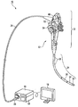
- an endoscope system 10 includes an endoscope (endoscope) including an observation optical system (imaging unit) and an illumination optical system (illumination unit) (not shown).
- Main body) 12 is detachably connected to the endoscope 12, and a light source device 14 that supplies illumination light to the endoscope 12, and an observation optical system of the endoscope 12 that is detachably connected to the endoscope 12.
- a video processor 16 for processing a signal obtained from the observation optical system and outputting a standard video signal, and a monitor 18 for displaying an endoscopic image obtained by the signal processing by the video processor 16.
- An image recording device (not shown) or the like can be connected to the video processor 16. Note that a small light source such as an LED may be built in the endoscope 12 instead of the light source device 14.
- the endoscope 12 is extended from the operation unit 22 and observed by an operation unit (endoscope body) 22 that can be held by an operator and can perform bending operations of first and second bending units 34 and 36 described later.
- a connector portion 28 is provided at an end portion of the universal cord 26 and is detachably connected to the light source device 14 and the video processor 16.
- the operation portion 22 is provided at the proximal end portion of the insertion portion 24.
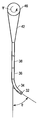
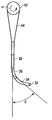
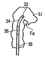
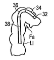
- the insertion portion 24 includes a distal end hard portion 32 provided at the distal end thereof, a bendable first bending portion 34 provided at the rear end side of the distal end hard portion 32, and a rear end side of the first bending portion 34.
- the distal end hard portion 32 includes an imaging unit in which a solid-state imaging device (not shown) such as a CCD or CMOS and a circuit board for driving the solid-state imaging device are incorporated as an observation optical system, or an observation inside a body cavity as an illumination optical system.
- a light guide (not shown) for transmitting illumination light for illuminating the target part is incorporated. For this reason, it is possible to irradiate the subject with illumination light from the distal end surface of the distal end hard portion 32, capture the illuminated subject with the imaging unit, and display the subject image on the monitor 18.
- the insertion portion 24 of the endoscope 12 includes two parts, the first bending portion 34 that is close to the distal end hard portion 32 and the second bending portion 36 that is close to the tubular portion 38. It has curved portions 34 and 36.
- the first bending portion 34 and the second bending portion 36 shown in FIG. 2 are respectively provided with bending tubes (first and second bending drive mechanisms) 34a and 36a formed of a plurality of known bending pieces, and outside the bending tube.
- a blade disposed and a skin disposed outside the blade For example, four angle wires (first bending drive mechanisms) 42 (U, D, R, L) corresponding to each bending direction of the first bending portion 34 are provided at the distal end of the bending tube 34a of the first bending portion 34. Is fixed. Further, for example, two angle wires (second bending drive mechanisms) 44 (U ′, D ′) are also fixed to the distal end of the bending tube 36 a of the second bending portion 36. Therefore, the first bending portion 34 is bent in the up / down (UP / DOWN) direction (indicated by U and D in FIG. 2) and in the left / right (RIGHT / LEFT) direction (indicated by R and L in FIG. 2). The second bending portion 36 can be bent in the vertical direction.
- first bending drive mechanisms 42 U, D, R, L
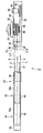
- the two angle wires 42 (U, D) for bending the first bending portion 34 in the vertical direction are wound around the first drum (first bending drive mechanism) 46 inside the operation portion 22.
- Two angle wires 42 (R, L) that bend the first bending portion 34 in the left-right direction are wound around and fixed to a second drum 48 inside the operation portion 22.
- the first and second drums 46 and 48 are arranged on the same axis.
- a first angle knob (bending operation input unit) 52 that rotates the first drum 46 and a second angle knob 54 that rotates the second drum 48 are disposed. Yes.
- the first and second angle knobs 52 and 54 are disposed on the same axis.
- the first and second drums 46 and 48 and the first and second angle knobs 52 and 54 are arranged on the same axis.
- the first angle knob 52 is rotated about its axis
- the first drum 46 is rotated about the same axis by the same angle as the first angle knob 52
- the second angle knob 54 is rotated about its axis.
- the second drum 48 rotates about the same axis by the same angle as the second angle knob 54.
- the bending tube 34a, the wire 42, and the first drum 46 form a first bending drive mechanism that bends the first bending portion 34.
- the position where the first bending portion 34 is straight is defined as the initial position of the first angle knob 52
- the position where the second bending portion 36 is straight is the initial position of the motor 64.
- the rotatable angle in the U direction (plus direction) and the D direction (minus direction) of the first angle knob 52 and the bendable angle ⁇ in the U direction and D direction of the first and second bending portions 34 and 36 are symmetrical. Preferably there is.
- the rotatable angle ⁇ of the first angle knob 52 and the bendable angle ⁇ of the first bending portion 34 are, for example, from the state (initial state) ⁇ 0 where the first bending portion 34 is straight in both the U direction and the D direction. It is preferably about 180 degrees.
- the rotatable angle of the second angle knob 54 and the bendable angle of the first bending portion 36 are each about 160 degrees, for example, from the straight state (initial state) of the first bending portion 34 in both the R direction and the L direction. Is preferred.
- the bendable angle ⁇ of the second bending portion 36 is preferably about 120 degrees, for example, from the state (initial state) ⁇ 0 where the second bending portion 36 is straight in both the U direction and the D direction.
- a knob position detecting potentiometer (input amount detecting unit) 56 for detecting the rotational position of the first drum 46 is attached to the first drum 46.
- the potentiometer 56 is disposed inside the operation unit 22. By setting the potentiometer 56 in accordance with the initial position of the first angle knob 52 (the position where the first bending portion 34 is straight), the potentiometer 56 can rotate the first drum 46, that is, the first angle knob 52. Can be detected. Therefore, the potentiometer 56 detects the bending operation amount input to the first angle knob (first bending operation input unit) 52 as the bending operation input amount.
- the two angle wires 44 (U ′, D ′) for bending the second bending portion 36 in the UD direction are connected to the third drum (second bending drive mechanism) 62 inside the operation portion 22. It is wound and fixed.
- the third drum 62 is provided with a motor (drive unit) 64 and an encoder (rotation position detection unit) 66 that detects the rotation amount (rotation angle) ⁇ (see FIG. 3B) of the motor (second bending drive mechanism) 64. ing.
- the motor 64 generates a driving force for bending the second bending portion 36. Therefore, the bending tube 36a, the wire 44, the third drum 62, and the motor 64 form a second bending drive mechanism that bends the second bending portion 36.
- the motor 64 and the encoder 66 are drawn so as to partially protrude outside the operation unit 22, but it is also preferable that they are arranged inside the operation unit 22. In addition, it is also preferable that the motor 64 is disposed not in the operation unit 22 but in the insertion unit 24.
- the second angle wires 44 (U ′, D ′) have slacks 44 a, 44 b in advance.
- the amount of sagging of the wire 44 is determined by rotating the motor 64 as shown in FIG. 4B from the state where the third drum 62 and the motor 64 shown in FIG. 4A are in the neutral position (the second bending portion 36 is straight). It is preferable that the slacks 44a and 44b remain slightly in the wires 44 (U ′, D ′) even when the second bending portion 36 is bent to the maximum bending angle in the U direction.
- the wires 44 (U ′, D ′) have sufficient slack 44a, 44b, so that the slack 44a, 44b is the first slack. 2 Since the bending portion 36 can be further bent in the U direction, or the amount of bending in the U direction can be reduced, there is play even in a state where the second bending portion 36 is bent, and the second bending portion 36 is forced. It does not curve in the opposite direction. Therefore, a large force is not applied to the inner wall of the tube hole. Although not shown, such a structure is preferably the same for the first bending portion 34 and the wire 42.
- the motor power source 72 shown in FIG. 5 A control microcomputer 74 shown in FIG. 5 for controlling the potentiometer 56, the motor 64, the encoder 66, and the motor power source 72 is disposed inside the operation unit 22.
- the motor power source 72 and the control microcomputer 74 are not limited to the inside of the operation unit 22 of the endoscope 12, and are preferably provided in any one of the light source device 14, the video processor 16, and the monitor 18, for example. .
- the motor power source 72 and the control microcomputer 74 are disposed in any one of the light source device 14, the video processor 16, and the monitor 18, for example, the motor power source 72 and the control microcomputer 74 are connected to the potentiometer 56, the motor via the universal cord 26. 64 and the encoder 66 are electrically connected. That is, the endoscope 12 itself may include a control microcomputer (control unit) 74, or the control microcomputer 74 may be disposed outside the endoscope 12 (the endoscope system 10 is a control microcomputer). 74).
- control microcomputer 74 control unit
- the control microcomputer 74 may be arranged in any of the endoscope 12 itself and devices of the endoscope system 10 other than the endoscope 12.
- the control microcomputer 74 when the control microcomputer 74 is connected to the endoscope 12, the case where the endoscope 12 itself has the control microcomputer 74 and the case where the control microcomputer 74 is disposed outside the endoscope 12.
- the endoscope 12 itself may be provided with a motor power source 72, or the motor power source 72 may be provided outside the endoscope 12 (the endoscope system 10 includes a motor power source 72. Just do it).
- the motor power source 72 may be disposed in any of the endoscope 12 itself and devices of the endoscope system 10 other than the endoscope 12.
- the motor power source 72 is connected to the endoscope 12
- the endoscope 12 itself has the motor power source 72
- the motor power source 72 is disposed outside the endoscope 12.
- the motor power source 72 includes a current measuring unit 82 that measures the current I that flows through the motor 64 and a voltage setting unit 84 that sets a voltage to be applied to the motor 64.
- the control microcomputer 74 calculates a CPU (control unit) 90, a resistance value measuring unit 92 that measures the resistance value of the potentiometer 56, a count processing unit 94 that counts the pulses of the encoder 66, and a torque T generated by the motor 64.
- a torque calculation unit (torque amount detection unit) 96, a threshold value input unit (setting unit) 98, and a storage unit 100 are included.
- the resistance value measurement unit 92, the count processing unit 94, the torque calculation unit 96, the threshold value input unit 98, and the storage unit 100 are electrically connected to the CPU 90 and controlled.
- the motor 64 is controlled by being electrically connected to the CPU 90. Therefore, by measuring the resistance value of the potentiometer 56 with the resistance value measuring unit 92 of the control microcomputer 74, the operation amount in the UD direction of the first angle knob 52, that is, the input amount (rotation angle) ⁇ can be obtained. The amount of bending of the first bending portion 34 in the UD direction can be estimated.
- the resistance value measuring unit 92 of the control microcomputer 74 functions as a bending amount calculating unit that calculates the bending amount of the first bending unit 34 that is driven to be bent by the first bending driving mechanism (the angle wire 42 and the first drum 46). To do. Further, the count processing unit 94 of the control microcomputer 74 can process the encoder pulse count of the encoder 66 to obtain the rotational position information (rotation angle) ⁇ of the motor 64.
- the control microcomputer 74 can calculate the torque T generated by the motor 64 by controlling the current I flowing through the motor 64. That is, the control microcomputer 74 can calculate the torque based on the current I measured by the current measuring unit 82 of the motor power source 72 and obtain the torque T generated by the motor 64.
- a threshold value input unit (threshold setting unit) 98 is used to set threshold angles ⁇ 0 , ⁇ 1 , ⁇ 2 , ⁇ 3 , ⁇ 4 to be described later.
- the storage unit 100 is used to store these threshold angles ⁇ 0 , ⁇ 1 , ⁇ 2 , ⁇ 3 , ⁇ 4, and the operation amount (rotation angle) ⁇ in the UD direction of the first angle knob 52, Rotational position information (rotational angle) ⁇ and the like can be stored.
- the rotation angle ⁇ of the first angle knob 52 corresponds to the bending angle ⁇ of the first bending portion 34.
- the rotation angle ⁇ of the motor 64 corresponds to the bending angle ⁇ of the second bending portion 36.
- the rotation angle ⁇ of the first angle knob 52 and the bending angle ⁇ of the first bending portion 34 will be described as being the same or substantially the same.
- the rotation angle ⁇ of the first angle knob 52 is rotated from 0 degree (straight state) to, for example, 90 degrees
- the first bending portion 34 also bends 90 degrees from the straight state (0 degree).
- the fulcrum of bending of the first bending portion 34 is the base end of the bending tube 34a of the first bending portion 34.
- the rotation angle ⁇ of the motor 64 and the bending angle ⁇ of the second bending portion 36 match or substantially match.
- the motor 64 is controlled to rotate the rotation angle ⁇ of the third drum 62 from 0 degrees to, for example, 90 degrees
- the second bending portion 36 also bends 90 degrees from a straight state.
- the fulcrum of bending of the second bending portion 36 is the base end of the bending tube 36a of the second bending portion 36.
- the rotational position of the motor 64 of the endoscope 12 in the linear state (neutral state) ⁇ 0 in which the second bending portion 36 is straight with no external force is measured, and this is set as the neutral position ⁇ 0 .
- the torque Tu 0 required to bend the second bending portion 36 in a straight state with no external force in the U direction by an angle ⁇ 1 (for example, 15 degrees) with respect to the neutral state (angle ⁇ 0 ) is measured.
- a torque Td 0 necessary for bending in the D direction by an angle ⁇ 2 (for example, ⁇ 15 degrees) is measured.
- the torques Tu 0 and Td 0 measured at this time are stored in the storage unit 100 of the control microcomputer 74.
- the angles ⁇ 1 (15 degrees) and ⁇ 2 ( ⁇ 15 degrees) are examples, and can be appropriately set by the threshold value input unit 98 within the range of the rotatable angle of the second bending section 36.
- the voltage of the motor power source 72 is set in order to cause the motor 64 to generate a torque Tu 0 , for example.
- PID control is a kind of feedback control, and is a method in which control of an input value is performed by three elements: a deviation between an output value and a target value, its integration, and differentiation.
- voltage information of the motor power source 72 is used as an input value
- torque information generated by the motor 64 is used as an output value
- PID control is applied using torque information derived in the control microcomputer 74 as a target value.
- the voltage information given to the motor power source 72 is derived.
- the generation of the target torque T of the motor 64 is realized by controlling the voltage of the motor power source 72.
- an input value voltage information of the motor power supply 72 is obtained from the rotation position information of the motor 64
- the rotation speed of the motor 64 uses a value calculated from the time difference of the rotation position information of the motor 64.
- Motor rotation speed V X (t2) ⁇ X (t1), t2> t1.
- X (t2) is the rotational position of the motor 64 at time t2
- X (t1) is the rotational position of the motor 64 at time t1.
- the second bending portion 36 is moved in the same direction as the bending direction of the first bending portion 34.
- the bending operation is performed using the motor 64, the third drum 62, the wire 44, and the bending tube 36a which are bending driving mechanisms will be described with reference to the flowchart shown in FIG.
- an example in which the first and second bending portions 34 and 36 are moved upward (U direction) will be mainly described.
- the threshold angle ⁇ 0 (for example, 5 degrees), ⁇ 1 (for example, 90 degrees), ⁇ 2 (for example, 25 degrees), ⁇ 3 (for example, ⁇ 90 degrees), ⁇ 4 (for example, ⁇ 25 degrees) is input by the threshold value input unit 98 Set.
- the threshold angle ⁇ 0 is preferably an arbitrary value between 0 degrees and 10 degrees, for example.
- the threshold angle ⁇ 1 of the angle ⁇ in the U direction of the first angle knob 52 detected by the potentiometer 56 is described as 90 degrees, but the threshold angle ⁇ 1 is not limited to 90 degrees. It can be set appropriately such as 80 degrees or 120 degrees.
- the threshold angle ⁇ 2 is not limited to 25 degrees, and can be set as appropriate, such as 20 degrees or 30 degrees.
- the threshold angles ⁇ 3 and ⁇ 4 can also be set as appropriate.
- the threshold angle ⁇ 1 is an angle larger than the threshold angle ⁇ 2
- the threshold angle ⁇ 3 is an angle smaller than the threshold angle ⁇ 4 . Since threshold angle [psi 3, [psi 4 is a negative value, the absolute value of the threshold angle [psi 3 is greater than the absolute value of the threshold angle [psi 4.
- the rotation angle ⁇ of the first angle knob 52 can be obtained by the potentiometer 56.
- ) of the rotation angle ⁇ of the first angle knob 52 becomes a predetermined threshold angle (for example, 5 degrees) ⁇ 0 or more, That is, the processing is started when an operation for bending the first bending portion 34 is started (S1).
- the determination of the start of such processing is performed by the CPU 90 and the storage unit 100 functioning as a determination unit.
- the determinations (S2, S3, S6, S7, S3 ′, S6 ′) described below are also performed by the CPU 90 and the storage unit 100 functioning as a determination unit.
- the rotation angle ⁇ is a positive value, it can be determined that the first angle knob 52 has started to rotate in the U direction, and if the rotation angle ⁇ is a negative value, it can be determined (S2).
- the rotation angle ⁇ is a positive value
- the rotation angle ⁇ is a negative value
- the potentiometer 56 While rotating the first angle knob 52 in the U direction, the potentiometer 56 obtains a rotation angle ⁇ in the U direction of the first angle knob 52.
- the rotation angle [psi in the U direction of the first angle knob 52 is threshold angle [psi 1 (for example, 90 degrees) or more, it is determined whether or less than the threshold angle [psi 1 (S3), is less than the angle [psi 1, the even when the second bending section 36 is subjected to an external force, by controlling the motor 64 (by outputting a bending driving signals from the CPU90 to the motor 64), is curved second curved portion 36 at a velocity V 0 in ( That is, with the torque Tu 1 added, the second bending portion 36 tries to maintain the neutral state (S4).
- the torque Tu 1 does not have to be constant, and the torque Tu 1 can prevent the second bending portion 36 from being bent in the U direction and can also be prevented from being bent in the D direction. Therefore, when the rotation angle in the U direction of the first angle knob 52 is larger than 0 degree, for example, smaller than the angle ⁇ 1 (for example, 90 degrees), even if the second bending portion 36 is curved by receiving an external force, The two bending portions 36 try to maintain a straight state.
- the CPU 90 When the rotation angle ⁇ of the first angle knob 52 obtained by the potentiometer 56 is equal to or larger than the angle ⁇ 1 (for example, 90 degrees), the CPU 90 outputs a bending drive signal to the motor 64 and causes the motor 64 to move the second bending portion 36.
- a constant torque (torque for bending the second bending portion 36 by 15 degrees in the U direction) Tu 0 is continuously generated to bend in the U direction (S5). That is, when the first bending portion 34 is bent by a predetermined angle (90 degrees), the predetermined torque Tu 0 is continuously applied to the second bending portion 36. For this reason, the second bending portion 36 is bent in the same U direction as the first bending portion 34 via the third drum 62 and the wire 44 with a constant torque Tu 0 .
- the rotation angle ⁇ of the first angle knob 52 becomes equal to or greater than the angle ⁇ 1 (for example, 90 degrees), even if the rotation angle ⁇ of the first angle knob 52 is decreased, the rotation angle ⁇ is still the angle ⁇ 2 (for example, 25). If it is degrees) or more (S6), continue to generate a certain amount of torque Tu 0 in motor 64. For this reason, the 2nd bending part 36 is maintained in the predetermined
- the rotation angle ⁇ of the first angle knob 52 becomes equal to or larger than the angle ⁇ 1 (for example, 90 degrees), the rotation angle ⁇ of the first angle knob 52 is decreased to be less than the angle ⁇ 2 (for example, 25 degrees) (S6). ), Controlling the motor 64 (outputting a bending drive signal from the CPU 90 to the motor 64), the amount of bending ( ⁇ ) is reduced toward the neutral position ⁇ 0 at the speed V 0 (S4). .
- the motor 64 is controlled.
- the bending amount ⁇ of the second bending portion 36 is reduced by an arbitrary torque Tu 2 (which does not need to be constant) so as to maintain the speed V 0 , and the second bending portion 36 is in a straight state (neutral position) ⁇ 0. (S4).
- is the case where the predetermined angle [psi 0 or continue processing described above. That is, when the rotation angle ⁇ of the first bending portion 34 is set to an angle ⁇ 1 (for example, 90 degrees) or more again (S3), a constant torque Tu 0 for causing the motor 64 to bend the second bending portion 36 in the U direction. Is generated (S5).
- the motor 64 is controlled to bend the second bending portion 36 at a constant speed ( ⁇ V 0 (speed opposite to the above-described speed V 0 )).
- the second bending portion 36 is maintained in the neutral state (ie, with the torque Td 1 applied) (S4 ′).
- the torque Td 1 does not need to be constant, and the torque Td 1 can prevent the second bending portion 36 from being bent in the UD direction, and the second bending portion 36 tries to maintain a straight state.
- the rotation angle ⁇ of the first angle knob 52 becomes equal to or smaller than the angle ⁇ 3 (for example, ⁇ 90 degrees), even if the rotation angle ⁇ of the first angle knob 52 is increased, the rotation angle ⁇ is still the angle ⁇ 4 (for example, If it is -25 degrees) or less (S6 '), continuing to generate torque Td 0 a certain amount by the motor 64. For this reason, the 2nd bending part 36 is maintained in the predetermined
- the rotation angle ⁇ of the first angle knob 52 becomes less than the angle ⁇ 3 (for example, ⁇ 90 degrees)
- the rotation angle ⁇ of the first angle knob 52 is increased to be larger than the angle ⁇ 4 (for example, ⁇ 25 degrees).
- the motor 64 is controlled to reduce the bending amount of the second bending portion 36 toward the neutral position ⁇ 0 at the speed ( ⁇ V 0) (S4 ′).
- the second bending portion 36 maintains a straight state before the first angle knob 52 is rotated to bend the first bending portion 34 by a predetermined bending amount ⁇ 1 (for example, 90 degrees).
- a predetermined bending angle ⁇ 1 for example, 90 degrees
- the second bending portion 36 can be bent in the same direction as the first bending portion 34.
- pre-bending angle eta of the first bending portion 34 is greater than the predetermined bending angle eta 1 (e.g. 90 degrees), or, after exceeding a predetermined bending angle eta 1 (e.g. 90 degrees), a predetermined bending angle eta When it becomes less than 2 (for example, 25 degrees), the 2nd bending part 36 can be made into a straight state.
- the rotation angle ⁇ of the first angle knob 52 detected by the potentiometer 56 is set by the threshold value input portion 98 in any case.
- the threshold value (first threshold value) ⁇ 1 , ⁇ 3 is larger than the absolute value, the second bending portion 36 is bent from the initial position ⁇ 0 to the predetermined bending amounts ⁇ 1 , ⁇ 2 , and the second Torques Tu 0 and Td 0 for maintaining the state where the bending portion 36 is bent to the predetermined bending amounts ⁇ 1 and ⁇ 2 are continuously applied to the motor 64.
- the second bending portion 36 is moved from the initial position ⁇ 0 to a predetermined bending amount ⁇ 1 in the same direction as the first bending portion 34 that is bent according to the rotation amount of the first angle knob 52.
- ⁇ 2 and the torques Tu 0 , Td 0 for maintaining the second bending portion 36 to be bent to the bending amounts ⁇ 1 , ⁇ 2 are continuously applied to the motor 64.
- the second bending portion 36 can be automatically bent in the same direction following the first bending portion 34 by the absolute values of the first threshold angles ⁇ 1 , ⁇ 3 set by the threshold input portion 98. . Therefore, by defining the bending direction of the second bending portion 36 in the same direction as that of the first bending portion 34, the state where the first bending portion 34 is hooked on a tube hole such as the large intestine is released unintentionally. Can be prevented, and the insertion property when the distal end of the insertion portion 24 is inserted into the back side can be improved.
- the motor 64 When the first bending portion 34 is bent, the motor 64 has torques Tu 0 , Td 0 , Tu 1 that prevent the second bending portion 36 from bending in a direction opposite to the bending direction of the first bending portion 34. , Td 1 , Tu 2 , Td 2 are added to the wire 44. For this reason, it can prevent more reliably that the state which bent the 1st bending part 34, for example, was hooked on the pipe hole, for example, is not intended unintentionally. Further, the motor 64 has a threshold value ⁇ 1 , after the rotation angle ⁇ of the first angle knob 52 by the potentiometer 56 exceeds the absolute values of the threshold values (first threshold values) ⁇ 1 and ⁇ 3 set by the threshold value input unit 98.
- the second bending portion 36 is maintained in a state of predetermined bending amounts ⁇ 1 , ⁇ 2 , and the threshold value (
- the second threshold value is smaller than the absolute values of ⁇ 2 , ⁇ 4 , torques Tu 2 , Td 2 for returning the second bending portion 36 to the initial position ⁇ 0 are added.
- the amount of bending of the first bending portion 34 is reduced, the amount of bending of the second bending portion 36 can be reduced following the amount of bending, so that the bending state of the two bending portions 34 and 36 can be simplified. Can be adjusted.
- the operation when the distal end of the insertion portion 24 of the endoscope 12 operating in this way is inserted toward the back side (for example, the small intestine or the stomach side) of the large intestine LI will be described.
- the operator holds the flexible tubular portion 38 of the insertion portion 24 with the right hand while holding the operation portion 22 of the endoscope 12 with the left hand.
- the tip of the insertion portion 24 is inserted toward the back side.
- the insertion portion 24 of the endoscope 12 when the distal end of the insertion portion 24 of the endoscope 12 is inserted into the back side of the sigmoid colon having the bent portions Fa and Fb of the large intestine LI shown in FIG. 7A, the insertion portion 24 is inserted into the bent portion Fa on the near side. Place the tip.
- the first angle knob 52 when the distal end of the insertion portion 24 is at the bent portion Fa of the large intestine LI, the first angle knob 52 is rotated, for example, in the U direction (see S1 and S2 in FIG. 6).
- the first bending portion 34 is gradually bent in the U direction (S3 in FIG. 6).
- the second bending portion 36 tries to maintain a straight state (S3 and S4 in FIG. 6). That is, the second bending portion 36 is prevented from being bent in the D direction, and the two bending portions 34 and 36 are prevented from being S-shaped as a whole.
- the distal end of the insertion portion 24 is moved to the back side while the first bending portion 34 in the bending portion Fa of the large intestine LI is bent to exceed 90 degrees in the U direction (FIG. 6).
- the second bending portion 36 maintains a straight state.
- the bending part Fa of large intestine LI will be pushed up. For this reason, the surgeon performs the procedure slowly and carefully so as not to apply a load to the large intestine LI.
- the first bending portion 34 is bent 90 degrees or more in the U direction (S3 in FIG. 6).
- the intent of bending the first bending portion 34 in the U direction by 90 degrees is to ensure that the first bending portion 34 is hooked on the bending portion Fa and to observe the back side of the bending portion Fa.
- the second bending portion 36 is bent in the same U direction as the first bending portion 34 (S5 in FIG. 6). Therefore, the distal end of the insertion portion 24 of the endoscope 12 moves toward the bent portion Fb on the back side of the bent portion Fa.
- the first bending portion 36 moves toward the bending portion Fb on the back side of the bending portion Fa, so that the bending portion Fa of the large intestine LI is pushed up by the first bending portion 34. Is alleviated. For this reason, the distal end of the insertion portion 24 automatically moves toward the back side of the large intestine LI.
- the bent portion Fa is firmly held by the first and second bending portions 34, 36, the large intestine LI can be pulled by pulling the insertion portion 24 toward the front side.
- the bending amount of the first bending portion 34 is 90 degrees or more, the inner wall near the bent portion Fa on the near side is observed rather than observing the bent portion Fb on the back side of the large intestine LI. For this reason, in order to observe the bending part Fb of the back
- the amount of bending of the first bending portion 34 is reduced, if the first bending portion 34 is 25 degrees or more, the second bending portion 36 has the distal end of the insertion portion 24 of the endoscope 12 at the back of the bending portion Fa. The same curved state as when moving toward the bent portion Fb on the side is maintained (S6 in FIG. 6).
- the bending amount of the first bending portion 34 is less than 25 degrees, as shown in FIG. 7F, the distal end of the insertion portion 24 of the endoscope 12 is moved toward the bending portion Fb on the back side of the bending portion Fa.
- the bending amount of the second bending portion 36 decreases at the speed V 0 (S6, S7 in FIG. 6).
- the 1st bending part 34 and the 2nd bending part 36 approach a straight state, and can easily move the front-end
- the flexible tubular portion 38 is bent because it passes through the bent portion Fa of the large intestine LI.
- the first and second angle knobs 52 and 54 are operated to move the first bending portion 34 in four directions, and the operation of causing the second bending portion 36 to follow the first bending portion 34 appropriately is repeated.
- the distal end of the insertion portion 24 of the endoscope 12 is gradually moved to the back side of the large intestine LI.
- the bending angle of the first bending portion 34 exceeds the threshold angle ⁇ 1 (for example, 90 degrees). Since the second bending portion 36 is automatically bent following the first bending portion 34 as shown in 7E, it is possible to prevent the insertion portion 24 of the endoscope 12 from applying a load to the large intestine LI as much as possible. .
- the endoscope system 10 can assist the insertion when inserting the distal end of the insertion portion 24 of the endoscope 12 into the back side of the winding tube. Therefore, when the endoscope system 10 according to the present embodiment is used, the second bending portion 36 is automatically moved following the operation of the first angle knob 52 of the operator, that is, the bending operation of the first bending portion 34. Since it operates so as to bend or keep straight, it is possible to assist an operator to insert the insertion portion 24 of the endoscope 12 into the deep side of the tube hole. For this reason, for example, even when performing a procedure that is difficult to insert into the inner side of the tube hole, such as the large intestine LI, the operator (operator) can easily operate the endoscope 12.
- the operator can perform the insertion operation of the insertion portion 24 more easily, so that from the anal side to the stomach or the small intestine side.
- the time it takes for the distal end of the insertion portion 24 to be inserted can be shortened, and the pain given to the patient is reduced.
- the second bending portion 36 can be maintained as a straight state or a bent state in the U direction, and the second bending portion 36 is bent in the D direction. It is preventing. Therefore, in order to insert the distal end of the insertion portion 24 into the back side of the large intestine LI, for example, the first bending portion 34 is bent nearly 180 degrees in the U direction, and the first bending portion 34 is hooked on the bending portion Fa of the large intestine LI. In this state, it is possible to prevent the second bending portion 36 from unintentionally bending in the D direction and releasing the state where the first bending portion 34 is hooked on the bent portion Fa.
- the second bending portion 36 has been described as being bent only in two directions of the U direction and the D direction.
- the second bending portion 36 may be configured to be bent in four directions.
- the first bending portion 34 is bent between the U direction and the R direction
- the second bending can be achieved by extending the flowchart shown in FIG. 6 to the case where the first bending portion 34 is bent in the R direction or the L direction.
- the portion 36 can be curved between the U direction and the R direction.
- This embodiment is a modification of the first embodiment, and the same members or members having the same functions as those described in the first embodiment are denoted by the same reference numerals, and detailed description thereof is omitted.
- the case of bending in the U direction is described as in the first embodiment, and the description of the case of bending in the D direction is omitted.
- the motor In the second bending portion 36 of the insertion portion 24 of the endoscope 12 in a straight state (rotational angle ⁇ 0 of the motor 64 and bending angle ⁇ 0 of the second bending portion 36) with no external force in advance, the motor The relationship between the rotation amount of 64 and the bending angle ⁇ of the second bending portion 36 is acquired in advance.
- the reason for acquiring the relationship between the rotation amount of the motor 64 and the bending angle ⁇ of the second bending portion 36 is that the rotation amount of the motor 64 and the bending angle ⁇ of the second bending portion 36 are not a simple proportional relationship. Because there is.
- the bending angle ⁇ of the second bending portion 36 can be estimated from the rotation amount of the motor 64, and this can be calculated as the estimated bending angle.
- ⁇ The rotation amount of the motor 64 can be acquired by the encoder 66 disposed in the motor 64 and is calculated by the encoder pulse count processing unit 94 of the control microcomputer 74.
- a relationship with the estimated bending angle ⁇ of 36 is acquired.
- the torque T of the motor 64 is calculated using the current I flowing through the motor 64.
- ⁇ is the inclination of the bending angle ⁇ of the second bending portion 36 with respect to the actual torque T of the motor 64
- Tr (real) is an intercept when the estimated bending angle ⁇ of the second bending portion 36 is 0 degrees.
- Tu ⁇ ⁇ ⁇ + Ti.
- the slopes ⁇ and ⁇ are preferably the same value so that the formulas (1) and (2) are parallel, and the intercept Tr is slightly larger than Ti (imaginary). That is, the intercept Ti in the formula (2) is set slightly smaller than the intercept Tr in the formula (1).
- the second bending portion 36 is bent in the same direction as the bending direction of the first bending portion 34.
- the case of performing the operation will be described with reference to the flowchart shown in FIG.
- an example in which the first and second bending portions 34 and 36 are moved upward (U direction) will be mainly described.
- the motor 64 causes the second bending portion 36 to be bent in the U direction.
- a constant torque (torque for bending the second bending portion 36 in the U direction by 15 degrees) Tu 0 is continuously generated (S5). For this reason, the second bending portion 36 is bent in the same U direction as the first bending portion 34 via the third drum 62 and the wire 44 with a constant torque Tu 0 .
- the estimated bending angle ⁇ of the second bending portion 36 is acquired by the rotation amount of the motor 64 when the second bending portion 36 is bent in the U direction, and this is substituted into the equation (2) to obtain the torque Tu. calculate.
- the torque Tu 0 is continuously applied to the third drum 62 by the motor 64 (S 5b ).
- the bending angle of the bending portion 36 in the U direction is increased.
- the estimated bending angle ⁇ of the second bending portion 36 is ⁇ 1 (for example, 15 degrees)
- the bending angle ⁇ of the second bending portion 36 is ⁇ when no external force is applied to the second bending portion 36. Stop at 1 (for example, 15 degrees). Up to this point, the process is the same as that described in the first embodiment.
- the estimated bending angle ⁇ increases.
- the motor 64 applies torque Tu to the third drum 62 based on the formula (2) (S 5c ).
- the estimated bending angle ⁇ is increased by the external force. Therefore, the torque 64 is continuously applied to the third drum 62 by the motor 64 based on the equation (2).
- the second bending portion 36 maintains the curved state when the external force is removed.
- the difference in torque between Equation (1) and Equation (2) is reduced, and the second curve is applied when an external force exceeding the difference between Equation (1) and Equation (2) is applied.
- the portion 36 can be bent in the U direction, and when the external force that is less than the difference between the equations (1) and (2) is applied, the bending state of the second bending portion 36 can be maintained. Therefore, when the external force exceeding the difference torque between Expression (1) and Expression (2) continues to work, the second bending portion 36 continues to bend to the maximum bending amount.
- the rotation angle ⁇ of the first angle knob 52 may be reduced.
- the rotation angle ⁇ is equal to or greater than ⁇ 2 (for example, 25 degrees) (S6)
- the motor 64 continues to generate a certain amount of torque Tu 0 .
- the rotation angle ⁇ of the first angle knob 52 becomes, for example, ⁇ 1 (for example, 90 degrees) or more
- the rotation angle ⁇ of the first angle knob 52 is decreased to, for example, less than ⁇ 2 (for example, 25 degrees).
- S6 controls the motor 64, reducing the bending amount at the speed V 0 toward the second curved portion 36 to the neutral position ⁇ 0 (S4).
- the motor 64 is driven with a large torque Tu in accordance with the bending amount ⁇ of the second bending portion 36, so that an external force is applied to the second bending portion 36.
- the external torque is applied to the second bending portion 36 by reducing the differential torque for maintaining the bending state of the second bending portion 36 (the difference between the formula (1) and the formula (2)). It can quickly demonstrate resistance to external forces. Therefore, for example, the first and second bending portions 34 and 36 can be bent along the shape of the tube hole, so that the operator of the endoscope 12 can insert the first bending portion 34 into the tube hole. Can be made easier.
- the second bending portion 36 tries to maintain a straight state (S4). That is, the second bending portion 36 is prevented from being bent in the D direction, and the two bending portions 34 and 36 are prevented from being S-shaped as a whole.
- S4 a straight state
- FIG. 7C when the distal end of the insertion portion 24 is moved backward while the first bending portion 34 in the bent portion F of the large intestine LI is bent 90 degrees in the U direction, as shown in FIG. 7D.
- the bent part Fa of the large intestine LI is pushed up. For this reason, the surgeon performs the procedure slowly and carefully so as not to apply a load to the large intestine LI. As shown in FIG.
- the second bending portion 36 is an endoscope.
- the same bending state as when the distal ends of the twelve insertion portions 24 move to the back side of the bent portion Fa is maintained.
- the second bending portion is moved while moving the distal end of the insertion portion 24 of the endoscope 12 to the back side of the bending portion Fa as shown in FIG. 7F.
- bending amount of 36 is reduced at the speed V 0. For this reason, as shown to FIG.
- the 1st bending part 34 and the 2nd bending part 36 approach a straight state, and the front-end
- the flexible tubular portion 38 is bent because it passes through the bent portion Fa of the large intestine LI.
- the second bending portion 36 In the case where an external force is applied to the second bending portion 36, when the first bending portion 34 is bent in the U direction, the second bending portion 36 is adjusted to be straight or bent in the U direction.
- the wire 44 When an external force is received from the U direction of the second bending portion 36, the wire 44 has the slacks (sag) 44a and 44b, so that a large force can be prevented from being applied to the second bending portion 36 abruptly.
- This embodiment is a modification of the first and second embodiments, and the same members or members having the same functions as those of the first and second embodiments are denoted by the same reference numerals and detailed description thereof is omitted. .
- the torque Tu 0 in the flowchart shown in FIG. 6 of the first embodiment can be replaced with the tension Fu 0, and the torque Td 0 can be replaced with the tension Fd 0 (see FIG. 11).
- the torque Tu 1 can be replaced with the tension Fu 1
- the torque Td 1 can be replaced with the tension Fd 1
- the torque Tu 2 can be replaced with the tension Fu 2
- the torque Td 2 can be replaced with the tension Fd 2 .
- the torque T of the motor 64 is calculated and various controls are performed.
- the tension F of the wire 44 is used.
- a tension sensor (not shown) may be used, or control using both the torque T of the motor 64 and the tension F of the wire 44 may be performed.
- the first angle knob 52 the first bending portion 34 may be operated (inputting the operation amount) using a joystick or the like. In this case, the first drum 46 is rotated by a motor (not shown).
- the endoscope has an insertion portion having a first bending portion and a second bending portion provided on the proximal end side of the first bending portion, and a bending operation for bending the first bending portion is input. And an input amount detection for detecting the bending operation input to the first bending operation input unit as a bending operation input amount.
- a bending amount calculation unit that performs bending, a second bending driving mechanism that bends the second bending unit, a driving unit that is coupled to the second bending driving mechanism and generates a driving force that drives the second bending driving mechanism,
- a first threshold value stored in advance and compared with the bending amount of the first bending portion is set.
- a setting unit; a determination unit that determines whether or not the bending amount of the first bending unit calculated by the bending amount calculation unit is greater than the first threshold; and the bending amount of the first bending unit by the determination unit Driving the second bending drive mechanism to cause the second bending portion to bend in the same direction as the bending direction of the first bending portion when it is determined that is greater than the first threshold.
- a control unit that continues to output to the unit.
- the first bending portion when the first bending portion is bent by a predetermined amount, it is determined that the first bending portion is hooked on the bent portion, and the second bending portion is bent, so that the first bending portion is bent.
- the distal end is inserted into the inner side of the tube hole, that is, moved to the inner side, and as a result, the insertion property when the distal end of the insertion portion is inserted into the inner side can be improved. That is, this endoscope can be more reliably inserted when the insertion portion is inserted into a tube hole having a bent portion such as the large intestine.
- the second bending drive mechanism includes a wire that connects the driving unit and the second bending unit, and the driving unit is configured to perform the second bending in a direction opposite to a direction in which the first bending unit is bent. It is preferable that a torque for preventing the portion from bending is applied to the wire. For this reason, it can prevent more reliably that the state which hooked the 1st bending part, for example in tube holes, such as large intestine, is not intended unintentionally.
- the second bending drive mechanism includes a wire that connects the driving unit and the second bending unit, and the driving unit is configured so that an input amount of the input amount detection unit exceeds an absolute value of the first threshold value.
- the absolute value of the second threshold value is smaller than the absolute value of the first threshold value, a torque for returning the second bending portion to the initial position is applied to the wire. .
- the amount of bending of the first bending portion is decreased, the amount of bending of the second bending portion can be tracked and decreased, so that the bending state of the two bending portions can be easily adjusted.
- the drive unit is connected to a torque amount detection unit that is provided in the drive unit and detects a torque amount applied to the drive unit, and the storage unit includes the second bending unit in an unloaded state at an initial position.
- the relationship between the torque added to the driving unit when the amount of bending is increased and detected by the torque amount detecting unit and the amount of bending of the second bending unit is stored, and the driving unit stores the second amount It is preferable to increase the bending amount of the bending portion and to apply a torque smaller than the torque with respect to the bending amount of the second bending portion stored in the storage portion to the driving portion. . For this reason, when the second bending portion is bent, the driving portion is driven with a large torque according to the bending amount of the second bending portion. Therefore, when an external force is applied to the second bending portion, The differential torque for maintaining the curved state can be reduced, and the resistance to external force can be improved.
- second angle knob 56 ... knob position detection potentiometer (operation input amount detection part), 62 ... drum (second bending drive mechanism), 64 ... motor (drive part, first bending drive mechanism) , 66 ... Encoder ( Position information detection unit) 72, motor power (torque amount detection unit, tension detection unit), 74 ... control microcomputer (control unit), 82 ... current measurement unit (torque amount detection unit, tension detection unit), 84 ... Voltage setting unit (torque amount detection unit, tension detection unit), 90 ... CPU, 92 ... resistance value measurement unit, 94 ... count processing unit, 96 ... torque calculation unit (torque amount detection unit), 98 ... threshold input unit (Threshold setting unit), 100... Storage unit.
Abstract
Description
上述したように、特開平6-217929号公報では、挿入部を押し込んだ際に曲がった部位が上方へ突張り挿入部を前進させることができない、となった場合に操作者のスイッチ操作により第1湾曲部の形状が記憶され、操作者が挿入部の挿入を継続すると同時に第2湾曲部の形状が記憶した第1湾曲部の形状と同じ形状となるように制御され、曲がった部位を上方へ突張らせないようにすることが開示されている。
しかし、特開平6-217929号公報では、挿入部により曲がった部位を上方に突っ張らせていると操作者が判断してからでなければ、第2湾曲部を第1湾曲部の形状と同じ形状とする制御を開始できず、曲がった部位を上方へ突張らせないようにすることができないという問題がある。
第1の実施の形態について図1から図7Gを用いて説明する。
先端硬質部32には、観察光学系としてCCDやCMOSなどの図示しない固体撮像素子及びこの固体撮像素子を駆動するための回路基板などが組み込まれた撮像部や、照明光学系として体腔内の観察対象部位を照明するための照明光を伝達する図示しないライトガイドなどが内蔵されている。このため、先端硬質部32の先端面から被写体に照明光を照射して、照明した被写体を撮像部で撮像して、モニタ18に被写体の像を表示させることができる。
図2に示す第1湾曲部34及び第2湾曲部36は、それぞれ公知の複数の湾曲駒で形成された湾曲管(第1及び第2湾曲駆動機構)34a,36aと、湾曲管の外側に配設されたブレードと、ブレードの外側に配設された外皮とを有する。第1湾曲部34の湾曲管34aの先端には、第1湾曲部34の各湾曲方向に対応して例えば4本のアングルワイヤ(第1湾曲駆動機構)42(U,D,R,L)が固定されている。また、第2湾曲部36の湾曲管36aの先端にも例えば2本のアングルワイヤ(第2湾曲駆動機構)44(U’,D’)が固定されている。このため、第1湾曲部34を上下(UP/DOWN)方向(図2中にU,Dで示す)及び左右(RIGHT/LEFT)方向(図2中にR,Lで示す)に湾曲させることが可能であり、第2湾曲部36を上下方向に湾曲させることが可能である。
なお、この実施形態では、第1湾曲部34が真っ直ぐの状態となる位置を第1アングルノブ52の初期位置として規定するとともに、第2湾曲部36が真っ直ぐの状態となる位置をモータ64の初期位置として規定する。そして、第1アングルノブ52のU方向(プラス方向)及びD方向(マイナス方向)の回転可能角度、第1及び第2湾曲部34,36のU方向及びD方向の湾曲可能角度ψは対称であることが好ましい。特に、第1アングルノブ52の回転可能角度ψ及び第1湾曲部34の湾曲可能角度ηは、U方向及びD方向ともに、第1湾曲部34が真っ直ぐの状態(初期状態)η0から例えばそれぞれ180度程度であることが好ましい。第2アングルノブ54の回転可能角度及び第1湾曲部36の湾曲可能角度は、R方向及びL方向ともに、第1湾曲部34が真っ直ぐの状態(初期状態)から例えばそれぞれ160度程度であることが好ましい。また、第2湾曲部36の湾曲可能角度θは、U方向及びD方向ともに、第2湾曲部36が真っ直ぐの状態(初期状態)θ0から例えばそれぞれ120度程度であることが好ましい。
なお、図1及び図2では、モータ64及びエンコーダ66は操作部22の外部に一部が突出するように描いたが、操作部22の内部に配置されていることも好ましい。また、モータ64は操作部22の内部ではなく、挿入部24の内部に配置されていることも好ましい。
なお、これらモータ電源72や制御マイコン74は、内視鏡12の操作部22の内部に限らず、例えば光源装置14、ビデオプロセッサ16、モニタ18のいずれかに設けられていることも好適である。モータ電源72や制御マイコン74が例えば光源装置14、ビデオプロセッサ16、モニタ18のいずれかに配設されている場合、これらモータ電源72及び制御マイコン74は、ユニバーサルコード26を介してポテンショメータ56、モータ64及びエンコーダ66に対して電気的に接続される。
すなわち、内視鏡12自体が制御マイコン(制御部)74を備えていても良いし、内視鏡12の外部に制御マイコン74が配設されていても良い(内視鏡システム10が制御マイコン74を備えていれば良い)。以下、本実施形態では、内視鏡12自体、及び、内視鏡12以外の内視鏡システム10の機器のいずれに制御マイコン(制御部)74が配置されていても良いものとして説明する。そして、内視鏡12に制御マイコン74が接続されている場合とは、内視鏡12自体が制御マイコン74を有する場合と、内視鏡12の外部に制御マイコン74が配設されている場合とを含む。
同様に、内視鏡12自体がモータ電源72を備えていても良いし、内視鏡12の外部にモータ電源72が配設されていても良い(内視鏡システム10がモータ電源72を備えていれば良い)。以下、本実施形態では、内視鏡12自体、及び、内視鏡12以外の内視鏡システム10の機器のいずれにモータ電源72が配置されていても良いものとして説明する。そして、内視鏡12にモータ電源72が接続されている場合とは、内視鏡12自体がモータ電源72を有する場合と、内視鏡12の外部にモータ電源72が配設されている場合とを含む。
制御マイコン74は、CPU(制御部)90と、ポテンショメータ56の抵抗値を測定する抵抗値測定部92と、エンコーダ66のパルスをカウントするカウント処理部94と、モータ64の発生トルクTを算出するトルク算出部(トルク量検知部)96と、閾値入力部(設定部)98と、記憶部100とを有する。
抵抗値測定部92、カウント処理部94、トルク算出部96、閾値入力部98及び記憶部100はCPU90に電気的に接続されて制御される。また、モータ64はCPU90に電気的に接続されて制御される。
このため、制御マイコン74の抵抗値測定部92で、ポテンショメータ56の抵抗値を測定することによって、第1アングルノブ52のUD方向の操作量、すなわち入力量(回転角度)ψを得ることができ、第1湾曲部34のUD方向の湾曲量を推定することができる。このため、制御マイコン74の抵抗値測定部92は第1湾曲駆動機構(アングルワイヤ42及び第1ドラム46)によって湾曲駆動された第1湾曲部34の湾曲量を算出する湾曲量算出部として機能する。また、制御マイコン74のカウント処理部94で、エンコーダ66のエンコーダパルスのカウントを処理してモータ64の回転位置情報(回転角度)ωを得ることができる。
この実施形態では、第1アングルノブ52の回転角度ψと、第1湾曲部34の湾曲角度ηとは一致又は略一致するものとして説明する。第1アングルノブ52の回転角度ψを0度(真っ直ぐの状態)から例えば90度に回転させた場合、第1湾曲部34も真っ直ぐの状態(0度)から90度湾曲する。なお、第1湾曲部34の湾曲の支点は第1湾曲部34の湾曲管34aの基端である。
モータ64の回転角度ωと第2湾曲部36の湾曲角度θとは一致又は略一致するものとする。モータ64を制御して第3ドラム62の回転角度ωを0度から例えば90度に回転させた場合、第2湾曲部36もまっすぐの状態から90度湾曲する。なお、第2湾曲部36の湾曲の支点は第2湾曲部36の湾曲管36aの基端である。
また、後述するように、速度V0で第2湾曲部36を中立位置(初期位置)θ0に向かわせる場合、モータ電源72の電圧情報を入力値とし、モータ64の回転位置情報から得られるモータ64の回転速度を出力値とし、制御マイコン74内で導出された速度情報を目標値として、PID制御を適用し、モータ電源72に与える電圧情報を導出することにより実現する。
なお、モータ64の回転速度は、モータ64の回転位置情報の時間差分により算出した値を利用する。モータ回転速度V=X(t2)-X(t1),t2>t1である。ここで、X(t2)は時刻t2でのモータ64の回転位置、X(t1)は時刻t1でのモータ64の回転位置である。
まず、閾値入力部98で閾値角度ψ0(例えば5度),ψ1(例えば90度),ψ2(例えば25度),ψ3(例えば-90度),ψ4(例えば-25度)を設定する。閾値角度ψ0は例えば0度から例えば10度の間の任意の値であることが好ましい。
なお、本実施形態では、ポテンショメータ56で検出される第1アングルノブ52のU方向の角度ψの閾値角度ψ1を90度として説明するが、閾値角度ψ1は90度に限ることはなく、80度や120度等、適宜に設定できる。また、閾値角度ψ2は25度に限ることはなく、20度や30度等、適宜に設定できる。閾値角度ψ3,ψ4も適宜に設定できる。ただし、閾値角度ψ1は閾値角度ψ2よりも大きい角度とし、閾値角度ψ3は閾値角度ψ4よりも小さい角度とする。なお、閾値角度ψ3,ψ4はマイナスの値であるため、閾値角度ψ3の絶対値は、閾値角度ψ4の絶対値よりも大きい。
第1アングルノブ52のD方向の回転角度ψが角度ψ3(例えば-90度)以下であるか、角度ψ3よりも大きいか判断し(S3’)、角度ψ3よりも大きい場合、第2湾曲部36が外力を受けた場合であっても、モータ64を制御して、一定の速度(-V0(上述した速度V0と逆方向の速度))で第2湾曲部36を湾曲させて(すなわち、トルクTd1を付加して)第2湾曲部36がニュートラル状態を維持する(S4’)。トルクTd1は、一定である必要はなく、トルクTd1によって第2湾曲部36がUD方向に湾曲させられるのを防止でき、第2湾曲部36は真っ直ぐの状態を維持しようとする。
このように、ポテンショメータ56によって検出された第1アングルノブ52の回転量(第1湾曲部34を湾曲させる湾曲量)が閾値入力部(設定部)98で設定した第1閾値角度ψ1,ψ3の絶対値よりも大きくなる場合に、第1アングルノブ52の回転量に応じて湾曲した第1湾曲部34と同じ方向に第2湾曲部36を初期位置θ0から所定の湾曲量θ1,θ2まで湾曲させてその第2湾曲部36を湾曲量θ1,θ2まで湾曲させた状態を維持するためのトルクTu0,Td0をモータ64に付加し続ける。このため、閾値入力部98で設定した第1閾値角度ψ1,ψ3の絶対値によって、第1湾曲部34に追従して第2湾曲部36を自動的に同じ方向に湾曲させることができる。したがって、第2湾曲部36の湾曲方向を第1湾曲部34と必ず同じ方向に規定することによって、第1湾曲部34を例えば大腸等の管孔に引っ掛けた状態が意図せず解除されるのを防止でき、挿入部24の先端を奥側に挿入する際の挿入性を向上させることができる。
また、モータ64には、ポテンショメータ56による第1アングルノブ52の回転角度ψが閾値入力部98で設定した閾値(第1閾値)ψ1,ψ3の絶対値を越えた後、閾値ψ1,ψ3の絶対値よりも小さい閾値(第2閾値)ψ2,ψ4の絶対値よりも大きい場合は第2湾曲部36を所定の湾曲量θ1,θ2の状態に維持し、閾値(第2閾値)ψ2,ψ4の絶対値よりも小さくした場合に、第2湾曲部36を初期位置θ0まで戻すトルクTu2,Td2を付加する。このため、第1湾曲部34の湾曲量を減少させたときに、第2湾曲部36の湾曲量を追従して減少させることができるので、2つの湾曲部34,36の湾曲状態を簡単に調整できる。
術者は内視鏡12の操作部22を左手で把持しながら、右手で挿入部24の可撓性を有する管状部38を保持する。この状態で、モニタ18の画面でいわゆる内視鏡画像を確認しつつ、第1及び第2アングルノブ52,54を左手で操作しながら、大腸LIの管腔(管孔)内を肛門側から奥側に向かって挿入部24の先端を挿入していく。
図7Bに示すように、挿入部24の先端が大腸LIの屈曲部Faにあるときに第1アングルノブ52を例えばU方向に回転させ(図6中のS1,S2参照)、挿入部24の第1湾曲部34をU方向に徐々に湾曲させる(図6中のS3)。このとき、第2湾曲部36に大腸LIの内壁が当たっても第2湾曲部36は真っ直ぐの状態を維持しようとする(図6中のS3,S4)。すなわち、第2湾曲部36がD方向に湾曲するのが防止され、2つの湾曲部34,36が全体としてS字状となるのが防止されている。
この実施形態においても、第1実施形態と同様にU方向に湾曲させる場合について説明し、D方向に湾曲させる場合については説明を省略する。
なお、モータ64の回転量は、モータ64に配設されたエンコーダ66で取得でき、制御マイコン74のエンコーダパルスのカウント処理部94で算出される。
なお、第2湾曲部36の推定湾曲角度θが小さい場合、モータ64のトルク量は大きく変化する。この範囲のモータ64のトルク量は、モータ64の起動抵抗やワイヤ44の摩擦等に使われる。このため、式(1)のTrは実際には推定値である。そして、式(1)により、第2湾曲部36が任意の角度θだけ湾曲させるために必要なトルクTを算出することができる。
このとき、外力が加えられ続けていれば、外力により推定湾曲角度θが増大する。このため、モータ64で第3ドラム62に式(2)に基づいてトルクTuを与え続ける。一方、外力が除去されると、第2湾曲部36は外力が除去されたときの湾曲状態が維持される。
なお、図9に示すフローチャートで第1湾曲部34をD方向に湾曲させる場合については角度をマイナス側に設定するだけであり、同様に動作させるので、説明を省略する。
図7Aに示す大腸LIのいわゆるS状結腸の奥側に内視鏡12の挿入部24の先端を挿入していく場合、手前側の屈曲部Faに挿入部24の先端を配置する。
図7Bに示すように、挿入部24の先端が大腸LIの屈曲部Fにあるときに第1アングルノブ52を例えばU方向に回転させ、挿入部24の第1湾曲部34をU方向に徐々に湾曲させる(S1-S3)。このとき、第2湾曲部36に大腸LIの内壁が当たっても第2湾曲部36は真っ直ぐの状態を維持しようとする(S4)。すなわち、第2湾曲部36がD方向に湾曲するのが防止され、2つの湾曲部34,36が全体としてS字状となるのが防止されている。
図7Cに示すように、大腸LIの屈曲部Fにある第1湾曲部34をU方向に90度湾曲させながら挿入部24の先端を奥側に移動させようとすると、図7Dに示すように、大腸LIの屈曲部Faを押し上げてしまう。このため、術者は大腸LIに負荷を与えないようにゆっくりと慎重に手技を行う。
図7Eに示すように、第1湾曲部34をU方向に90度以上湾曲させると、第2湾曲部36が第1湾曲部34と同じU方向に湾曲する。このため、内視鏡12の挿入部24の先端が屈曲部Faの奥側に移動する。第2湾曲部36の例えばD方向側の面が大腸LIの内周面に当接すると、第2湾曲部36は大腸LIの内周面から外力を受ける。そして、第2湾曲部36の推定湾曲角度θが所定の角度θ1(例えば15度)以上となったときモータ64はトルクTu0よりも高いトルクTuを第3ドラム62に与える。このため、第1湾曲部34及び第2湾曲部36で大腸LIを押し上げそうになると、第2湾曲部36に次第に大きなトルクが加えられて大腸LIの内壁から離れるように第2湾曲部36の湾曲角度を増大させる。一方、第2湾曲部36のD方向側の面が大腸LIの内壁から離れると、第2湾曲部36の湾曲状態が維持される。すなわち、第1湾曲部34を第1アングルノブ52を操作してU方向に湾曲させ、挿入部24を奥側に押し込む動作と組み合わせることによって、第2湾曲部36のD方向側の面に外力が加えられるので、大腸LIの形状に沿って挿入部24の先端を挿入していくことができる。
また、第1アングルノブ52の代わりに、ジョイスティック等を用いて第1湾曲部34を操作(操作量を入力)しても良い。この場合、図示しないモータで第1ドラム46を回転させる。
内視鏡は、第1湾曲部と、前記第1湾曲部の基端側に設けられた第2湾曲部とを有する挿入部と、前記第1湾曲部を湾曲させる湾曲操作が入力される第1の湾曲操作入力部を有し、前記挿入部の基端側に設けられた操作部と、前記第1湾曲操作入力部に入力された前記湾曲操作を湾曲操作入力量として検出する入力量検出部と、前記湾曲操作入力量に応じた湾曲量に前記第1湾曲部を湾曲させる第1湾曲駆動機構と、前記第1湾曲駆動機構によって湾曲駆動された前記第1湾曲部の湾曲量を算出する湾曲量算出部と、前記第2湾曲部を湾曲させる第2湾曲駆動機構と、前記第2湾曲駆動機構に連結され、前記第2湾曲駆動機構を駆動させる駆動力を発生する駆動部と、予め記憶され、前記第1湾曲部の湾曲量と比較される第1閾値が設定される設定部と、前記湾曲量算出部で算出される第1湾曲部の湾曲量が前記第1閾値よりも大きいか否かを判定する判定部と、前記判定部により前記第1湾曲部の湾曲量が前記第1閾値よりも大きいと判定された場合に前記第2湾曲駆動機構を駆動させて前記第2湾曲部が前記第1湾曲部の湾曲方向と同じ方向へ湾曲させる湾曲駆動信号を前記駆動部に対して出力し続ける制御部とを有することを特徴とする。
このように、第1湾曲部が所定量湾曲された場合に第1湾曲部が曲がった部位に引掛けられたものと判断し、第2の湾曲部を湾曲させることで、第1湾曲部の先端は管孔の奥側に挿入、すなわち奥側に移動することになり、結果、挿入部の先端を奥側に挿入する際の挿入性を向上させることができる。
すなわち、この内視鏡は、例えば大腸等、曲がった部位を有する管孔に挿入部を挿入していく際により確実に挿入することができる。
このため、第1湾曲部を例えば大腸等の管孔に引っ掛けた状態が意図せず解除されるのをより確実に防止できる。
前記第2湾曲駆動機構は、前記駆動部と前記第2湾曲部とを接続するワイヤを備え、前記駆動部は、前記入力量検出部の入力量が前記第1閾値の絶対値を越えた後、前記第1閾値の絶対値よりも小さい第2閾値の絶対値よりも小さくした場合に、前記第2湾曲部を前記初期位置まで戻すトルクを前記ワイヤに付加するようにしたことが好適である。
このため、第1湾曲部の湾曲量を減少させたときに、第2湾曲部の湾曲量を追従して減少させることができるので、2つの湾曲部の湾曲状態を簡単に調整できる。
このため、第2湾曲部を湾曲させる際、第2湾曲部の湾曲量に応じて大きなトルクで駆動部を駆動させるので、第2湾曲部に外力が加えられたときに、第2湾曲部の湾曲状態を維持するための差分トルクを少なくして、外力に対する耐性を良好にすることができる。
Claims (9)
- 第1湾曲部と、前記第1湾曲部の基端側に設けられた第2湾曲部とを有する挿入部と、
前記第1湾曲部を湾曲させる湾曲操作が入力される第1の湾曲操作入力部を有し、前記挿入部の基端側に設けられた操作部と、
前記第1の湾曲操作入力部に入力された前記湾曲操作を湾曲操作入力量として検出する入力量検出部と、
前記湾曲操作入力量に応じた湾曲量に前記第1湾曲部を湾曲させる第1湾曲駆動機構と、
前記第1湾曲駆動機構によって湾曲駆動された前記第1湾曲部の湾曲量を算出する湾曲量算出部と、
前記第2湾曲部を湾曲させる第2湾曲駆動機構と、
前記第2湾曲駆動機構に連結され、前記第2湾曲駆動機構を駆動させる駆動力を発生する駆動部と、
予め記憶され、前記第1湾曲部の湾曲量と比較される第1閾値が設定される設定部と、
前記湾曲量算出部で算出される第1湾曲部の湾曲量が前記第1閾値よりも大きいか否かを判定する判定部と、
前記判定部により前記第1湾曲部の湾曲量が前記第1閾値よりも大きいと判定された場合に前記第2湾曲駆動機構を駆動させて前記第2湾曲部が前記第1湾曲部の湾曲方向と同じ方向へ湾曲させる湾曲駆動信号を前記駆動部に対して出力し続ける制御部と、
を有する、内視鏡。 - 前記駆動部は、前記制御部からの湾曲駆動信号により第2湾曲部を湾曲させるためのトルクを発生させるようにした、請求項1に記載の内視鏡。
- 前記第2湾曲駆動機構は、前記駆動部と前記第2湾曲部とを接続するワイヤを備え、
前記駆動部は、前記制御部により前記第1湾曲部が湾曲している方向と反対の方向に前記第2湾曲部が湾曲するのを防止するトルクを前記ワイヤに付加するようにした、請求項1に記載の内視鏡。 - 前記第2湾曲部には初期位置が設定され、
前記第2湾曲駆動機構は、前記駆動部と前記第2湾曲部とを接続するワイヤを備え、
前記駆動部は、前記入力量検出部の入力量が前記第1閾値の絶対値を越えた後、前記第1閾値の絶対値よりも小さい第2閾値の絶対値よりも小さくした場合に、前記第2湾曲部を前記初期位置まで戻すトルクを前記ワイヤに付加するようにした、請求項1に記載の内視鏡。 - 前記第2湾曲部には初期位置が設定され、
前記制御部は記憶部を有し、
前記駆動部には、前記駆動部に設けられ前記駆動部に付加されるトルク量を検知するトルク量検知部が接続され、
前記記憶部には、無負荷状態の前記第2湾曲部を初期位置から湾曲量を増大させたときに前記駆動部に付加され前記トルク量検知部により検知されるトルクと、前記第2湾曲部の湾曲量との関係が記憶され、
前記駆動部は、前記第2湾曲部の湾曲量が大きくなるにつれて増大させ、かつ、前記記憶部に記憶された前記第2湾曲部の湾曲量に対するトルクよりも小さいトルクを前記駆動部に付加するようにした、請求項1に記載の内視鏡。 - 前記第2湾曲駆動機構は、前記駆動部と前記第2湾曲部とを接続するワイヤを備え、
前記駆動部は、前記第1湾曲部が湾曲している方向と反対の方向に前記第2湾曲部が湾曲するのを防止する張力を前記ワイヤに付加するようにした、請求項1に記載の内視鏡。 - 前記第2湾曲駆動機構は、前記駆動部と前記第2湾曲部とを接続するワイヤを備え、
前記駆動部は、前記入力量検出部の入力量が前記第1閾値の絶対値を越えた後、前記第1閾値の絶対値よりも小さい第2閾値の絶対値よりも小さくした場合に、前記第2湾曲部を前記初期位置まで戻す張力を前記ワイヤに付加するようにした、請求項1に記載の内視鏡。 - 前記制御部は記憶部を有し、
前記第2湾曲駆動機構は、前記第2湾曲部と前記駆動部とを連結するワイヤと、前記ワイヤに付加される張力を検知する張力検知部とをさらに有し、
前記記憶部には、無負荷状態の前記第2湾曲部を初期位置から湾曲量を増大させたときに前記駆動部を介して前記ワイヤに付加され前記張力検知部により検知される張力と、前記第2湾曲部の湾曲量との関係が記憶され、
前記駆動部は、前記第2湾曲部の湾曲量が大きくなるにつれて増大させ、かつ、前記記憶部に記憶された前記第2湾曲部の湾曲量に対する張力よりも小さい張力を前記ワイヤに付加するようにした、請求項1に記載の内視鏡。 - 前記第1閾値は、その絶対値が90度である、請求項1に記載の内視鏡。
Priority Applications (4)
| Application Number | Priority Date | Filing Date | Title |
|---|---|---|---|
| EP12763890.6A EP2583616B1 (en) | 2011-03-29 | 2012-02-21 | Endoscope |
| CN201280002478.7A CN103079451B (zh) | 2011-03-29 | 2012-02-21 | 内窥镜 |
| JP2012543834A JP5165162B2 (ja) | 2011-03-29 | 2012-02-21 | 内視鏡 |
| US13/626,559 US8708892B2 (en) | 2011-03-29 | 2012-09-25 | Endoscope with controlled bending sections |
Applications Claiming Priority (2)
| Application Number | Priority Date | Filing Date | Title |
|---|---|---|---|
| JP2011-073039 | 2011-03-29 | ||
| JP2011073039 | 2011-03-29 |
Related Child Applications (1)
| Application Number | Title | Priority Date | Filing Date |
|---|---|---|---|
| US13/626,559 Continuation US8708892B2 (en) | 2011-03-29 | 2012-09-25 | Endoscope with controlled bending sections |
Publications (1)
| Publication Number | Publication Date |
|---|---|
| WO2012132637A1 true WO2012132637A1 (ja) | 2012-10-04 |
Family
ID=46930398
Family Applications (1)
| Application Number | Title | Priority Date | Filing Date |
|---|---|---|---|
| PCT/JP2012/054088 WO2012132637A1 (ja) | 2011-03-29 | 2012-02-21 | 内視鏡 |
Country Status (5)
| Country | Link |
|---|---|
| US (1) | US8708892B2 (ja) |
| EP (1) | EP2583616B1 (ja) |
| JP (1) | JP5165162B2 (ja) |
| CN (1) | CN103079451B (ja) |
| WO (1) | WO2012132637A1 (ja) |
Cited By (3)
| Publication number | Priority date | Publication date | Assignee | Title |
|---|---|---|---|---|
| WO2015129368A1 (ja) * | 2014-02-26 | 2015-09-03 | オリンパス株式会社 | 医療用システムの制御方法 |
| WO2019239545A1 (ja) * | 2018-06-14 | 2019-12-19 | オリンパス株式会社 | 内視鏡システムおよび挿入部の推進方法 |
| WO2021201081A1 (ja) * | 2020-03-31 | 2021-10-07 | 東レ株式会社 | 湾曲検出機能付き基部材、湾曲検出システム、湾曲検出機能付き基部材を備えた機器及びバルーンカテーテル |
Families Citing this family (31)
| Publication number | Priority date | Publication date | Assignee | Title |
|---|---|---|---|---|
| US9955994B2 (en) | 2002-08-02 | 2018-05-01 | Flowcardia, Inc. | Ultrasound catheter having protective feature against breakage |
| US7335180B2 (en) | 2003-11-24 | 2008-02-26 | Flowcardia, Inc. | Steerable ultrasound catheter |
| US7604608B2 (en) * | 2003-01-14 | 2009-10-20 | Flowcardia, Inc. | Ultrasound catheter and methods for making and using same |
| US7758510B2 (en) | 2003-09-19 | 2010-07-20 | Flowcardia, Inc. | Connector for securing ultrasound catheter to transducer |
| CN104114074B (zh) * | 2012-07-09 | 2016-11-02 | 奥林巴斯株式会社 | 导入装置系统 |
| JP6293145B2 (ja) | 2012-08-02 | 2018-03-14 | バード・ペリフェラル・バスキュラー・インコーポレーテッド | 超音波カテーテルシステム |
| EP2908733B1 (en) | 2012-10-17 | 2020-07-29 | Worcester Polytechnic Institute | System for underactuated control of insertion path for asymmetric tip needles |
| US9549666B2 (en) | 2012-11-10 | 2017-01-24 | Curvo Medical, Inc. | Coaxial micro-endoscope |
| JP6132585B2 (ja) * | 2013-02-21 | 2017-05-24 | オリンパス株式会社 | 被検体挿入システム |
| US20140275779A1 (en) * | 2013-03-12 | 2014-09-18 | Covidien Lp | Flexible Shaft with Multiple Flexible Portions |
| CN103330544B (zh) * | 2013-06-18 | 2015-01-21 | 深圳市亚泰光电技术有限公司 | 内窥镜弯曲控制机构及内窥镜 |
| JP5830628B2 (ja) | 2013-07-08 | 2015-12-09 | オリンパス株式会社 | 導入装置 |
| US10118021B2 (en) | 2013-09-30 | 2018-11-06 | St. Jude Medical, Cardiology Division, Inc. | Catheter having an active return-to-straight mechanism |
| WO2015072233A1 (ja) * | 2013-11-14 | 2015-05-21 | オリンパスメディカルシステムズ株式会社 | 挿入機器、回転ユニット及び挿入装置 |
| CN106102632B (zh) * | 2014-03-17 | 2019-06-14 | 直观外科手术操作公司 | 在程序中重启期间修复器械控制输入方位/定向 |
| WO2015194317A1 (ja) * | 2014-06-19 | 2015-12-23 | オリンパス株式会社 | 内視鏡装置 |
| EP3209192A4 (en) | 2014-10-20 | 2019-01-16 | Research Development International Corporation | STEERING MICROENDOSCOPE |
| CN107405045B (zh) * | 2015-03-26 | 2021-02-09 | 奥林巴斯株式会社 | 挠性管插入装置 |
| AU2017214552B2 (en) | 2016-02-05 | 2020-08-27 | Board Of Regents Of The University Of Texas System | Surgical apparatus |
| CA3004201C (en) | 2016-02-05 | 2023-01-10 | Board Of Regents Of The University Of Texas System | Steerable intra-luminal medical device |
| DE112016006985T5 (de) * | 2016-06-20 | 2019-02-28 | Olympus Corporation | Einführvorrichtung für einen flexiblen Tubus |
| US20180140321A1 (en) | 2016-11-23 | 2018-05-24 | C. R. Bard, Inc. | Catheter With Retractable Sheath And Methods Thereof |
| US20180147014A1 (en) * | 2016-11-30 | 2018-05-31 | Wipro Limited | Ureteroscope and a method for dusting stones in a body cavity |
| US11596726B2 (en) | 2016-12-17 | 2023-03-07 | C.R. Bard, Inc. | Ultrasound devices for removing clots from catheters and related methods |
| US10582983B2 (en) | 2017-02-06 | 2020-03-10 | C. R. Bard, Inc. | Ultrasonic endovascular catheter with a controllable sheath |
| DE102017103819A1 (de) * | 2017-02-24 | 2018-08-30 | Hoya Corporation | Endoskop mit mehreren Biegeabschnitten |
| KR102391591B1 (ko) * | 2017-05-16 | 2022-04-27 | 박연호 | 가요성 연성부 형태 추정 장치 및 이를 포함하는 내시경 시스템 |
| US11918762B2 (en) | 2018-10-03 | 2024-03-05 | St. Jude Medical, Cardiology Division, Inc. | Reduced actuation force electrophysiology catheter handle |
| DE112019006478B4 (de) * | 2018-12-28 | 2023-11-16 | Hoya Corporation | Endoskop und Endoskopsystem |
| US11872357B2 (en) | 2020-11-09 | 2024-01-16 | Agile Devices, Inc. | Devices for steering catheters |
| CN117100197B (zh) * | 2023-10-23 | 2024-02-20 | 杭州堃博生物科技有限公司 | 鞘管调弯方法、装置、非易失性存储介质及电子设备 |
Citations (8)
| Publication number | Priority date | Publication date | Assignee | Title |
|---|---|---|---|---|
| JPS62292134A (ja) * | 1986-06-12 | 1987-12-18 | 旭光学工業株式会社 | 内視鏡の湾曲部 |
| JPH04246322A (ja) * | 1991-02-01 | 1992-09-02 | Olympus Optical Co Ltd | 内視鏡装置 |
| JPH06217929A (ja) | 1993-01-29 | 1994-08-09 | Olympus Optical Co Ltd | 可撓管 |
| JP2004230189A (ja) * | 2004-04-30 | 2004-08-19 | Olympus Corp | 内視鏡装置 |
| JP2009279405A (ja) * | 2008-05-19 | 2009-12-03 | Olympus Medical Systems Corp | 湾曲管及び医療機器 |
| JP2010000201A (ja) * | 2008-06-19 | 2010-01-07 | Olympus Medical Systems Corp | 内視鏡 |
| JP2010220961A (ja) * | 2009-03-25 | 2010-10-07 | Fujifilm Corp | 内視鏡システムの湾曲部調整装置および湾曲部調整方法 |
| WO2011040104A1 (ja) * | 2009-09-30 | 2011-04-07 | オリンパスメディカルシステムズ株式会社 | 内視鏡装置及び湾曲駆動制御方法 |
Family Cites Families (10)
| Publication number | Priority date | Publication date | Assignee | Title |
|---|---|---|---|---|
| JPH06217919A (ja) | 1993-01-28 | 1994-08-09 | Matsushita Electric Works Ltd | 食器洗浄機 |
| US5876325A (en) * | 1993-11-02 | 1999-03-02 | Olympus Optical Co., Ltd. | Surgical manipulation system |
| US6468203B2 (en) * | 2000-04-03 | 2002-10-22 | Neoguide Systems, Inc. | Steerable endoscope and improved method of insertion |
| JP3600194B2 (ja) * | 2000-10-02 | 2004-12-08 | オリンパス株式会社 | 内視鏡 |
| JP4323441B2 (ja) * | 2005-02-14 | 2009-09-02 | オリンパス株式会社 | 内視鏡 |
| WO2006134881A1 (ja) * | 2005-06-14 | 2006-12-21 | Olympus Medical Systems Corp. | 内視鏡処置具及び内視鏡用処置具装置 |
| JP2007054125A (ja) * | 2005-08-22 | 2007-03-08 | Olympus Medical Systems Corp | 内視鏡 |
| JP2009160211A (ja) * | 2008-01-07 | 2009-07-23 | Fujifilm Corp | 内視鏡湾曲操作装置及び内視鏡 |
| US8409079B2 (en) * | 2008-05-14 | 2013-04-02 | Olympus Medical Systems Corp. | Electric bending operation device and medical treatment system including electric bending operation device |
| DE102008047776B4 (de) | 2008-09-17 | 2012-11-22 | Richard Wolf Gmbh | Endoskopisches Instrument |
-
2012
- 2012-02-21 EP EP12763890.6A patent/EP2583616B1/en not_active Not-in-force
- 2012-02-21 JP JP2012543834A patent/JP5165162B2/ja active Active
- 2012-02-21 CN CN201280002478.7A patent/CN103079451B/zh active Active
- 2012-02-21 WO PCT/JP2012/054088 patent/WO2012132637A1/ja active Application Filing
- 2012-09-25 US US13/626,559 patent/US8708892B2/en active Active
Patent Citations (8)
| Publication number | Priority date | Publication date | Assignee | Title |
|---|---|---|---|---|
| JPS62292134A (ja) * | 1986-06-12 | 1987-12-18 | 旭光学工業株式会社 | 内視鏡の湾曲部 |
| JPH04246322A (ja) * | 1991-02-01 | 1992-09-02 | Olympus Optical Co Ltd | 内視鏡装置 |
| JPH06217929A (ja) | 1993-01-29 | 1994-08-09 | Olympus Optical Co Ltd | 可撓管 |
| JP2004230189A (ja) * | 2004-04-30 | 2004-08-19 | Olympus Corp | 内視鏡装置 |
| JP2009279405A (ja) * | 2008-05-19 | 2009-12-03 | Olympus Medical Systems Corp | 湾曲管及び医療機器 |
| JP2010000201A (ja) * | 2008-06-19 | 2010-01-07 | Olympus Medical Systems Corp | 内視鏡 |
| JP2010220961A (ja) * | 2009-03-25 | 2010-10-07 | Fujifilm Corp | 内視鏡システムの湾曲部調整装置および湾曲部調整方法 |
| WO2011040104A1 (ja) * | 2009-09-30 | 2011-04-07 | オリンパスメディカルシステムズ株式会社 | 内視鏡装置及び湾曲駆動制御方法 |
Non-Patent Citations (1)
| Title |
|---|
| See also references of EP2583616A4 |
Cited By (7)
| Publication number | Priority date | Publication date | Assignee | Title |
|---|---|---|---|---|
| WO2015129368A1 (ja) * | 2014-02-26 | 2015-09-03 | オリンパス株式会社 | 医療用システムの制御方法 |
| JP2015159891A (ja) * | 2014-02-26 | 2015-09-07 | オリンパス株式会社 | 医療用システムの制御方法 |
| CN106028902A (zh) * | 2014-02-26 | 2016-10-12 | 奥林巴斯株式会社 | 医疗用系统的控制方法 |
| US10588485B2 (en) | 2014-02-26 | 2020-03-17 | Olympus Corporation | Medical-system control method |
| WO2019239545A1 (ja) * | 2018-06-14 | 2019-12-19 | オリンパス株式会社 | 内視鏡システムおよび挿入部の推進方法 |
| US11931007B2 (en) | 2018-06-14 | 2024-03-19 | Olympus Corporation | Endoscope system and propulsion method for insertion section |
| WO2021201081A1 (ja) * | 2020-03-31 | 2021-10-07 | 東レ株式会社 | 湾曲検出機能付き基部材、湾曲検出システム、湾曲検出機能付き基部材を備えた機器及びバルーンカテーテル |
Also Published As
| Publication number | Publication date |
|---|---|
| EP2583616B1 (en) | 2015-04-01 |
| JPWO2012132637A1 (ja) | 2014-07-24 |
| CN103079451B (zh) | 2015-07-15 |
| US8708892B2 (en) | 2014-04-29 |
| EP2583616A4 (en) | 2013-06-26 |
| EP2583616A1 (en) | 2013-04-24 |
| CN103079451A (zh) | 2013-05-01 |
| JP5165162B2 (ja) | 2013-03-21 |
| US20130109919A1 (en) | 2013-05-02 |
Similar Documents
| Publication | Publication Date | Title |
|---|---|---|
| JP5165162B2 (ja) | 内視鏡 | |
| JP5301867B2 (ja) | 医療用マニピュレータシステム | |
| US8454497B2 (en) | Endoscope apparatus and bending drive control method | |
| US9161682B2 (en) | Medical system and control method | |
| JP5000503B2 (ja) | 内視鏡処置具 | |
| JP4896264B2 (ja) | 内視鏡装置 | |
| JP5193401B2 (ja) | 医療用制御装置 | |
| US8597178B2 (en) | Active drive type medical apparatus and drive control method | |
| US8403833B2 (en) | Medical apparatus | |
| JP5559996B2 (ja) | 内視鏡装置及び内視鏡システム並びに内視鏡装置の作動方法 | |
| JP5851139B2 (ja) | 医療装置 | |
| US8974376B2 (en) | Introducing device system with bending control | |
| JP2006230620A (ja) | 内視鏡装置 | |
| JP5841366B2 (ja) | 医療装置 | |
| JP5324953B2 (ja) | 内視鏡 | |
| WO2019003272A1 (ja) | 可撓管挿入装置、挿入制御装置及び挿入制御プログラム | |
| JP5232679B2 (ja) | 内視鏡 | |
| JP4520485B2 (ja) | 電動湾曲内視鏡 | |
| JP5049824B2 (ja) | 内視鏡 | |
| JP2011019549A (ja) | 内視鏡装置及び内視鏡システム並びに内視鏡装置の制御方法 |
Legal Events
| Date | Code | Title | Description |
|---|---|---|---|
| WWE | Wipo information: entry into national phase |
Ref document number: 201280002478.7 Country of ref document: CN |
|
| ENP | Entry into the national phase |
Ref document number: 2012543834 Country of ref document: JP Kind code of ref document: A |
|
| 121 | Ep: the epo has been informed by wipo that ep was designated in this application |
Ref document number: 12763890 Country of ref document: EP Kind code of ref document: A1 |
|
| WWE | Wipo information: entry into national phase |
Ref document number: 2012763890 Country of ref document: EP |
|
| NENP | Non-entry into the national phase |
Ref country code: DE |