WO2011036890A1 - トルクロッド - Google Patents
トルクロッド Download PDFInfo
- Publication number
- WO2011036890A1 WO2011036890A1 PCT/JP2010/005772 JP2010005772W WO2011036890A1 WO 2011036890 A1 WO2011036890 A1 WO 2011036890A1 JP 2010005772 W JP2010005772 W JP 2010005772W WO 2011036890 A1 WO2011036890 A1 WO 2011036890A1
- Authority
- WO
- WIPO (PCT)
- Prior art keywords
- outer cylinder
- torque rod
- bush
- diameter bush
- diameter
- Prior art date
- Legal status (The legal status is an assumption and is not a legal conclusion. Google has not performed a legal analysis and makes no representation as to the accuracy of the status listed.)
- Ceased
Links
Images


Classifications
-
- F—MECHANICAL ENGINEERING; LIGHTING; HEATING; WEAPONS; BLASTING
- F16—ENGINEERING ELEMENTS AND UNITS; GENERAL MEASURES FOR PRODUCING AND MAINTAINING EFFECTIVE FUNCTIONING OF MACHINES OR INSTALLATIONS; THERMAL INSULATION IN GENERAL
- F16F—SPRINGS; SHOCK-ABSORBERS; MEANS FOR DAMPING VIBRATION
- F16F1/00—Springs
- F16F1/36—Springs made of rubber or other material having high internal friction, e.g. thermoplastic elastomers
- F16F1/38—Springs made of rubber or other material having high internal friction, e.g. thermoplastic elastomers with a sleeve of elastic material between a rigid outer sleeve and a rigid inner sleeve or pin, i.e. bushing-type
- F16F1/3842—Method of assembly, production or treatment; Mounting thereof
- F16F1/3849—Mounting brackets therefor, e.g. stamped steel brackets; Restraining links
-
- Y—GENERAL TAGGING OF NEW TECHNOLOGICAL DEVELOPMENTS; GENERAL TAGGING OF CROSS-SECTIONAL TECHNOLOGIES SPANNING OVER SEVERAL SECTIONS OF THE IPC; TECHNICAL SUBJECTS COVERED BY FORMER USPC CROSS-REFERENCE ART COLLECTIONS [XRACs] AND DIGESTS
- Y10—TECHNICAL SUBJECTS COVERED BY FORMER USPC
- Y10T—TECHNICAL SUBJECTS COVERED BY FORMER US CLASSIFICATION
- Y10T74/00—Machine element or mechanism
- Y10T74/21—Elements
- Y10T74/2142—Pitmans and connecting rods
Definitions
- the present invention relates to a torque rod for automobiles, and more particularly to a torque rod excellent in durability and easy to manufacture.
- a bush including a pair of metal inner cylinders and an outer cylinder connected to an outer peripheral surface thereof via a rubber member is integrally interconnected by a connecting member.
- the outer cylinder of the large bush and the outer cylinder and the connecting portion of the small bush are formed by press-molding a single annular metal plate.
- a technique has been proposed in which the outer cylinder and the connecting portion are integrally formed and joined by spot welding at the connecting portion in which two plates are overlapped.
- the present invention is to provide a torque rod having a pair of bushes whose axial directions are perpendicular to each other, particularly a torque rod capable of increasing the strength of an outer cylinder of a large-diameter bush.
- the torque rod according to the present invention includes an inner cylinder and an outer cylinder, each of which has a large-diameter bush and a small-diameter bush that are perpendicular to each other in the axial direction. Is formed by a combined joined body by plastic working of two metal plates, and a protrusion protruding from the outer peripheral side of the outer cylinder of the large-diameter bush is formed.
- the outer cylinder of the large-diameter bush is more preferably formed by bending a metal plate.
- the outer cylinder of the small-diameter bush is formed by drawing on each metal plate.
- a gap is formed along the longitudinal direction of the connecting member.
- each of the connecting members is constituted by a combined joined body by plastic processing of two metal plates, and a protrusion protruding on the outer peripheral side of the outer cylinder of the large-diameter bush is formed.
- the strength of the outer cylinder can be increased, and the rigidity can be improved in the direction in which the diameter of the outer cylinder is increased due to vibration such as torque from the vibration generating side member.
- FIG. 1 is a side view showing an embodiment of a torque rod of the present invention
- FIG. 2 is a cross-sectional perspective view showing a part of each bush.
- the torque rod 1 shown in the figure has a bush having a pair of cylindrical inner cylinders 2, a rubber member 3 surrounding the inner cylinders 2, and an outer cylinder made of a metal material.
- the bush is interconnected by a connecting member 4.
- the pair of bushes includes a large-diameter bush 5 and a small-diameter bush 6 having different diameters, and the axial directions of the bushes 5 and 6 are connected perpendicularly to each other.
- the large-diameter bush 5 is configured such that the rubber member 3 is directly fixed to the entire surface of the inner cylinder 2 and the upper cylinder 7 by the vulcanization adhesion or the rubber member 3 is press-fitted into the outer cylinder 7. Can be formed.
- the outer cylinder 7 is formed with a bent portion 7a that holds the rubber member 3 between the upper and lower positions in the figure, and the bent portion 7a can prevent the rubber member from falling off.
- the strength in the extending direction of the connecting member 4 as shown in FIG. 3 can be increased, and in particular, deformation of the storage dimension of the outer cylinder 8 that stores the rubber member 3 can be prevented.
- the small-diameter bush 6 directly fixes the rubber member 3 to the inner cylinder 2 and the outer cylinder 8 by vulcanization adhesion.
- Such a torque rod 1 can absorb, mitigate, or the like, transmission of vibration or the like during rotational driving from the inner cylinder side to the outer cylinder side, for example, by the rubber member 3.
- the outer cylinder can exert a resistance against the force in the separation direction and the force in the proximity direction with respect to the inner cylinders.
- the torque rod 1 is preferably formed by combining the connecting member 4 and the outer cylinders 7 and 8 into a desired shape by plastic working of two metal plates, and welding them together in a combined joined body. Since it comprises, it is not necessary to connect each outer cylinder and a connection member, Therefore It is not necessary to perform operations, such as positioning, reducing a number of parts, and can achieve cost reduction.
- a projection 9 is formed on the outer diameter side of the outer cylinder 7 of the large-diameter bush 5, that is, at a position facing the connecting member 4 in the drawing.
- the outer cylinder 7 of the large-diameter bush 5 is bent in the drawing to form a step by bending the metal plate.
- the bent portion 7a can be formed by bending in the axial direction.
- the amount of the metal plate drawn into the outer cylinder 7 of the large-diameter bush 5 is less than that of the outer cylinder of the large-diameter bush formed by the conventional drawing process, and the yield of the members is improved. Can be reduced.
- the outer cylinder 8 of the small-diameter bush 6 is formed by drawing, and this configuration improves the yield and also prevents the large-diameter bush 5 from rotating off the shaft and preventing the axial bush from coming off.
- the rigidity between the large diameter bush 5 and the small diameter bush 6 can be improved.
- the drawing process can be performed by, for example, forming a seamless container with a bottom by tightening the outer periphery of a flat metal plate.
- FIG. 4 is a side view showing another embodiment of the torque rod of the present invention.
- the gap portion 10 is formed as large as possible in consideration of the strength of the connection member 4 along the longitudinal direction of the connection member 4. Can be reduced in weight.
- the torque rod 1 is formed by simultaneously forming two outer metal plates by press forming, by pressing, an outer cylinder of a predetermined small-diameter bush, and an outer cylinder of a predetermined large-diameter bush by bending. While welding them at a position where they face each other, each bush can be obtained by press-fitting the inner cylinder and the rubber member into the narrowed portion and the bent portion of the 2-press weld bracket.
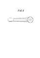
- FIG. 5 is a side view showing another embodiment of the torque rod of the present invention.
- ribs 11 projecting from the outer cylinder 7 to the outer peripheral side over the connecting member 4 are formed, and the connecting member 4 is provided with four ribs 11 at intervals of about 90 ° in the circumferential direction thereof.
- the rigidity of the metal plate can be increased by increasing the section modulus of the metal plate located at the connecting portion.
Landscapes
- Engineering & Computer Science (AREA)
- General Engineering & Computer Science (AREA)
- Manufacturing & Machinery (AREA)
- Mechanical Engineering (AREA)
- Vibration Prevention Devices (AREA)
- Springs (AREA)
- Vibration Dampers (AREA)
Priority Applications (3)
| Application Number | Priority Date | Filing Date | Title |
|---|---|---|---|
| US13/497,728 US20120255395A1 (en) | 2009-09-25 | 2010-09-24 | Torque rod |
| CN2010800426466A CN102575743A (zh) | 2009-09-25 | 2010-09-24 | 转矩杆 |
| IN2573DEN2012 IN2012DN02573A (https=) | 2009-09-25 | 2010-09-24 |
Applications Claiming Priority (2)
| Application Number | Priority Date | Filing Date | Title |
|---|---|---|---|
| JP2009221162A JP5595702B2 (ja) | 2009-09-25 | 2009-09-25 | トルクロッド |
| JP2009-221162 | 2009-09-25 |
Publications (1)
| Publication Number | Publication Date |
|---|---|
| WO2011036890A1 true WO2011036890A1 (ja) | 2011-03-31 |
Family
ID=43795657
Family Applications (1)
| Application Number | Title | Priority Date | Filing Date |
|---|---|---|---|
| PCT/JP2010/005772 Ceased WO2011036890A1 (ja) | 2009-09-25 | 2010-09-24 | トルクロッド |
Country Status (5)
| Country | Link |
|---|---|
| US (1) | US20120255395A1 (https=) |
| JP (1) | JP5595702B2 (https=) |
| CN (1) | CN102575743A (https=) |
| IN (1) | IN2012DN02573A (https=) |
| WO (1) | WO2011036890A1 (https=) |
Families Citing this family (4)
| Publication number | Priority date | Publication date | Assignee | Title |
|---|---|---|---|---|
| JP5986464B2 (ja) * | 2012-09-18 | 2016-09-06 | 住友理工株式会社 | トルクロッド |
| JP6113501B2 (ja) * | 2012-12-28 | 2017-04-12 | 東洋ゴム工業株式会社 | 防振連結ロッド |
| JP5986521B2 (ja) * | 2013-02-26 | 2016-09-06 | 住友理工株式会社 | 防振装置 |
| US9694637B2 (en) * | 2015-02-13 | 2017-07-04 | Douglas H. Powell | Flexible joint for a suspension link with a threaded insert |
Citations (3)
| Publication number | Priority date | Publication date | Assignee | Title |
|---|---|---|---|---|
| JP2005291448A (ja) * | 2004-04-02 | 2005-10-20 | Tokai Rubber Ind Ltd | 流体封入式の防振連結ロッド |
| JP2006283870A (ja) * | 2005-03-31 | 2006-10-19 | Tokai Rubber Ind Ltd | トルクロッド |
| JP2008249113A (ja) * | 2007-03-30 | 2008-10-16 | Tokai Rubber Ind Ltd | トルクロッド及びその製造方法 |
Family Cites Families (11)
| Publication number | Priority date | Publication date | Assignee | Title |
|---|---|---|---|---|
| US1839680A (en) * | 1929-06-24 | 1932-01-05 | Irene Hudson | Connecting rod |
| US4360284A (en) * | 1980-10-08 | 1982-11-23 | General Motors Corporation | Ball-joint assembly |
| US5165306A (en) * | 1990-10-04 | 1992-11-24 | Maclean-Fogg Company | Vehicle stabilizer bar end link |
| DE4441219C2 (de) * | 1994-11-19 | 2001-12-06 | Zf Lemfoerder Metallwaren Ag | Pendelstütze für das Einsetzen von die Lagerstellen bildenden Lagerhüben für die gelenkige Verbindung von Fahrwerksteilen in Kraftfahrzeugen |
| JPH08152034A (ja) * | 1994-11-28 | 1996-06-11 | Tokai Rubber Ind Ltd | エンジンマウント取付部材 |
| JPH09291928A (ja) * | 1996-02-29 | 1997-11-11 | Ntn Corp | 鋼板製連接棒 |
| JP3716750B2 (ja) * | 2001-02-23 | 2005-11-16 | 東海ゴム工業株式会社 | 防振ブッシュ付スタビライザーバー |
| JP4436103B2 (ja) * | 2003-10-03 | 2010-03-24 | 株式会社ブリヂストン | トルクロッド構造 |
| JP2008002615A (ja) * | 2006-06-23 | 2008-01-10 | Hosei Brake Ind Ltd | トルクロッド |
| CN201236912Y (zh) * | 2008-07-11 | 2009-05-13 | 奇瑞汽车股份有限公司 | 一种汽车用橡胶衬套 |
| EP2502764B1 (en) * | 2011-03-22 | 2014-01-15 | Edai Technical Unit, A.I.E. | Stabilizer link for a vehicle suspension and method for obtaining it |
-
2009
- 2009-09-25 JP JP2009221162A patent/JP5595702B2/ja active Active
-
2010
- 2010-09-24 WO PCT/JP2010/005772 patent/WO2011036890A1/ja not_active Ceased
- 2010-09-24 IN IN2573DEN2012 patent/IN2012DN02573A/en unknown
- 2010-09-24 US US13/497,728 patent/US20120255395A1/en not_active Abandoned
- 2010-09-24 CN CN2010800426466A patent/CN102575743A/zh active Pending
Patent Citations (3)
| Publication number | Priority date | Publication date | Assignee | Title |
|---|---|---|---|---|
| JP2005291448A (ja) * | 2004-04-02 | 2005-10-20 | Tokai Rubber Ind Ltd | 流体封入式の防振連結ロッド |
| JP2006283870A (ja) * | 2005-03-31 | 2006-10-19 | Tokai Rubber Ind Ltd | トルクロッド |
| JP2008249113A (ja) * | 2007-03-30 | 2008-10-16 | Tokai Rubber Ind Ltd | トルクロッド及びその製造方法 |
Also Published As
| Publication number | Publication date |
|---|---|
| US20120255395A1 (en) | 2012-10-11 |
| CN102575743A (zh) | 2012-07-11 |
| JP2011069440A (ja) | 2011-04-07 |
| IN2012DN02573A (https=) | 2015-08-28 |
| JP5595702B2 (ja) | 2014-09-24 |
Similar Documents
| Publication | Publication Date | Title |
|---|---|---|
| EP2540534B1 (en) | Suspension structure, bush structure and suspension characteristic adjusting method | |
| JP6343535B2 (ja) | 筒型防振装置 | |
| JP5780638B2 (ja) | 防振ブッシュおよびその製造方法 | |
| WO2014192081A1 (ja) | 車両用リンク部品およびその製造方法 | |
| JP5595702B2 (ja) | トルクロッド | |
| JP2010023713A (ja) | 金属製アーム部材及びその製造方法 | |
| CN103661632A (zh) | 由复合材料的两个管道和支柱构成的机动车辆的仪表盘横梁 | |
| JP2010031926A (ja) | ダイナミックダンパ | |
| JP2005282701A (ja) | 防振ゴムブッシュとその製造方法 | |
| JP2016161049A (ja) | リンクブラケット | |
| JP5959918B2 (ja) | ブラケット及び防振連結ロッド | |
| JP2008095861A (ja) | 防振ブッシュ及びリンク部材 | |
| WO2014057779A1 (ja) | ボールジョイント用ダストカバー | |
| JP2004028267A (ja) | 防振ブッシュ | |
| JP2010023714A (ja) | 車両用サスペンションアーム | |
| CN213206399U (zh) | 组合式衬套 | |
| KR101254050B1 (ko) | 현가부재 및 그 제조방법 | |
| JP2018161989A (ja) | 自動車の後部サスペンション構造 | |
| JP2010038195A (ja) | トルクロッド及びその製造方法 | |
| JP2007192240A (ja) | 連結ロッド | |
| JP4699294B2 (ja) | 防振装置 | |
| JP7044469B2 (ja) | 防振装置 | |
| JP2013221595A (ja) | 軸受構造体および製造方法 | |
| JP7673952B2 (ja) | ラックピニオン式ステアリングギヤユニット | |
| JP4511422B2 (ja) | ブッシュ組立体 |
Legal Events
| Date | Code | Title | Description |
|---|---|---|---|
| WWE | Wipo information: entry into national phase |
Ref document number: 201080042646.6 Country of ref document: CN |
|
| 121 | Ep: the epo has been informed by wipo that ep was designated in this application |
Ref document number: 10818567 Country of ref document: EP Kind code of ref document: A1 |
|
| WWE | Wipo information: entry into national phase |
Ref document number: 2573/DELNP/2012 Country of ref document: IN |
|
| NENP | Non-entry into the national phase |
Ref country code: DE |
|
| WWE | Wipo information: entry into national phase |
Ref document number: 13497728 Country of ref document: US |
|
| 122 | Ep: pct application non-entry in european phase |
Ref document number: 10818567 Country of ref document: EP Kind code of ref document: A1 |