WO2011036801A1 - 電子ビーム記録装置 - Google Patents
電子ビーム記録装置 Download PDFInfo
- Publication number
- WO2011036801A1 WO2011036801A1 PCT/JP2009/066791 JP2009066791W WO2011036801A1 WO 2011036801 A1 WO2011036801 A1 WO 2011036801A1 JP 2009066791 W JP2009066791 W JP 2009066791W WO 2011036801 A1 WO2011036801 A1 WO 2011036801A1
- Authority
- WO
- WIPO (PCT)
- Prior art keywords
- turntable
- electron beam
- displacement
- rotational shake
- recording apparatus
- Prior art date
- Legal status (The legal status is an assumption and is not a legal conclusion. Google has not performed a legal analysis and makes no representation as to the accuracy of the status listed.)
- Ceased
Links
Images





Classifications
-
- G—PHYSICS
- G11—INFORMATION STORAGE
- G11B—INFORMATION STORAGE BASED ON RELATIVE MOVEMENT BETWEEN RECORD CARRIER AND TRANSDUCER
- G11B7/00—Recording or reproducing by optical means, e.g. recording using a thermal beam of optical radiation by modifying optical properties or the physical structure, reproducing using an optical beam at lower power by sensing optical properties; Record carriers therefor
- G11B7/24—Record carriers characterised by shape, structure or physical properties, or by the selection of the material
- G11B7/26—Apparatus or processes specially adapted for the manufacture of record carriers
-
- G—PHYSICS
- G11—INFORMATION STORAGE
- G11B—INFORMATION STORAGE BASED ON RELATIVE MOVEMENT BETWEEN RECORD CARRIER AND TRANSDUCER
- G11B5/00—Recording by magnetisation or demagnetisation of a record carrier; Reproducing by magnetic means; Record carriers therefor
- G11B5/84—Processes or apparatus specially adapted for manufacturing record carriers
-
- G—PHYSICS
- G11—INFORMATION STORAGE
- G11B—INFORMATION STORAGE BASED ON RELATIVE MOVEMENT BETWEEN RECORD CARRIER AND TRANSDUCER
- G11B7/00—Recording or reproducing by optical means, e.g. recording using a thermal beam of optical radiation by modifying optical properties or the physical structure, reproducing using an optical beam at lower power by sensing optical properties; Record carriers therefor
- G11B7/08—Disposition or mounting of heads or light sources relatively to record carriers
- G11B7/09—Disposition or mounting of heads or light sources relatively to record carriers with provision for moving the light beam or focus plane for the purpose of maintaining alignment of the light beam relative to the record carrier during transducing operation, e.g. to compensate for surface irregularities of the latter or for track following
- G11B7/095—Disposition or mounting of heads or light sources relatively to record carriers with provision for moving the light beam or focus plane for the purpose of maintaining alignment of the light beam relative to the record carrier during transducing operation, e.g. to compensate for surface irregularities of the latter or for track following specially adapted for discs, e.g. for compensation of eccentricity or wobble
- G11B7/0953—Disposition or mounting of heads or light sources relatively to record carriers with provision for moving the light beam or focus plane for the purpose of maintaining alignment of the light beam relative to the record carrier during transducing operation, e.g. to compensate for surface irregularities of the latter or for track following specially adapted for discs, e.g. for compensation of eccentricity or wobble to compensate for eccentricity of the disc or disc tracks
-
- G—PHYSICS
- G11—INFORMATION STORAGE
- G11B—INFORMATION STORAGE BASED ON RELATIVE MOVEMENT BETWEEN RECORD CARRIER AND TRANSDUCER
- G11B9/00—Recording or reproducing using a method not covered by one of the main groups G11B3/00 - G11B7/00; Record carriers therefor
- G11B9/10—Recording or reproducing using a method not covered by one of the main groups G11B3/00 - G11B7/00; Record carriers therefor using electron beam; Record carriers therefor
Definitions
- the present invention relates to an electron beam recording apparatus, and more particularly to an electron beam recording apparatus that manufactures a master disk of a high-speed rotating recording medium such as a magnetic disk using an electron beam.
- Beam recording devices that perform lithography using exposure beams such as electron beams and laser beams are digital versatile discs (DVD: Digital Versatile Disc), optical discs such as Blu-ray discs, and large-capacity discs such as hard discs for magnetic recording. It is widely applied to the master production equipment.
- DVD Digital Versatile Disc
- optical discs such as Blu-ray discs
- large-capacity discs such as hard discs for magnetic recording. It is widely applied to the master production equipment.
- a resist layer is formed on the recording surface of a substrate that becomes a master in manufacturing the above-described disc, and the substrate is rotated and translated to move the beam spot relative to the substrate recording surface.
- control is performed so that a spiral or concentric track locus is drawn on the substrate recording surface to form a latent image on the resist.
- rotational shake occurs due to mechanical accuracy such as a feed motor and a spindle motor that rotate and translate the substrate, and the track formation accuracy is lowered. Therefore, it is necessary to perform beam exposure while correcting the rotational shake by some method.
- the rotational vibration of the disk substrate does not depend on the synchronous vibration (synchronous rotational vibration), which is a vibration component synchronized with the rotational frequency of the turntable (substrate), and the rotational frequency of the turntable (substrate).
- synchronous rotational vibration a vibration component synchronized with the rotational frequency of the turntable (substrate), and the rotational frequency of the turntable (substrate).
- asynchronous runout asynchronous runout
- Patent Document 1 discloses a technique for correcting asynchronous rotational shake for the purpose of improving track pitch accuracy (relative positional accuracy with adjacent tracks) in an optical disc master exposure apparatus.
- the hard disk has a high rotational speed during recording and reproduction, and the control band of the swing arm type control mechanism for performing the track control of the recording and reproduction head is narrow, so the track roundness accuracy required for the disk medium is severe. Therefore, a master exposure apparatus for producing such a disk medium needs to correct not only asynchronous rotational shake but also synchronous rotational shake with high accuracy.
- a radial displacement (hereinafter also referred to as a radial displacement) of the turntable measured at a predetermined number of revolutions or less is used as a reference displacement, and a difference of the radial displacement measured in real time during beam exposure with respect to the reference displacement is calculated.
- the irradiation position control (correction) of the recording beam is performed based on the calculation result (see, for example, Patent Document 2).
- JP-A-9-190651 page 4, FIG. 1
- Japanese Patent Laid-Open No. 2003-317285 page 7-8, FIG. 3
- An example of the present invention is to provide a high-accuracy electron beam recording apparatus capable of correcting rotational shake on the order of sub-nanometers to nanometers.
- An electron beam recording apparatus is an electron that forms a latent image on a resist layer by irradiating the resist layer formed on the substrate with an electron beam according to a recording signal while rotating the turntable on which the substrate is placed.
- a beam recording apparatus comprising a displacement detector having at least three displacement sensors arranged at different angles in the radial direction of the turntable and detecting the displacement of the rotating side surface of the turntable in the radial direction, and a perfect circle of the turntable Based on the shape calculator that calculates the shape data based on the degree error and the eccentric component of the turntable, the memory that stores the shape data, the detected displacement from the displacement sensor when the turntable is rotated, and the shape data,
- a rotational runout calculator that calculates rotational runout that does not include the eccentric component of the turntable, and the above rotation It is characterized by having a beam irradiation position adjuster for adjusting the irradiation position of the electron beam on the basis of the record.
- An electron beam recording apparatus is an electron beam recording apparatus that performs recording by irradiating an electron beam on a substrate according to a recording signal while rotating a turntable on which the substrate is mounted.
- a displacement sensor for detecting displacement information in a direction
- an eccentric component acquisition means for acquiring an eccentric component due to eccentricity of the turntable based on the displacement information
- rotational shake information by subtracting the eccentric component from the displacement information
- a beam irradiation position adjuster that adjusts the irradiation position of the electron beam based on the rotation vibration information.
- An electron beam recording apparatus is an electron beam recording apparatus that performs recording by irradiating an electron beam on a substrate in accordance with a recording signal while rotating a turntable on which the substrate is mounted.
- Displacement data acquisition means for acquiring displacement data that is displacement in a direction
- eccentric component acquisition means for acquiring an eccentric component due to eccentricity of the turntable
- rotational shake information obtained by removing the eccentric component from the displacement data
- a beam irradiation position adjuster that adjusts the irradiation position of the electron beam based on the rotation shake information.
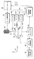
- FIG. 1 is a block diagram schematically showing a configuration of an electron beam recording apparatus that is an embodiment of the present invention. It is a figure shown about the structure which detects and calculates rotational shake, and adjusts the irradiation position of an electron beam (EB) based on the said calculation result. It is a top view which shows typically arrangement
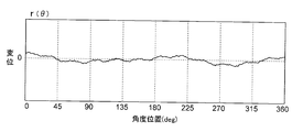
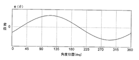
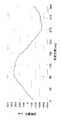
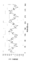
- FIG. 5 is a diagram illustrating a waveform example of roundness error data r ( ⁇ ). It is a figure which shows the example of a waveform of eccentric data e ((theta)). It is a figure which shows the example of a waveform of the calculated shape data f ((theta)).
- FIG. 6 is a block diagram showing a configuration in a case where exposure beam irradiation position correction is performed while updating shape data f ( ⁇ ) during exposure.
- FIG. 1 is a block diagram schematically showing the configuration of an electron beam recording apparatus 10 that is an embodiment of the present invention.
- the electron beam recording apparatus 10 is a disk mastering apparatus that creates an original disk for manufacturing a hard disk using an electron beam.
- the electron beam recording apparatus 10 includes a vacuum chamber 11, a driving device that places, rotates, and translates the substrate 15 disposed in the vacuum chamber 11, an electron beam column 20 attached to the vacuum chamber 11, and a substrate Various circuits and control systems for driving control and electron beam control are provided.
- the substrate 15 for the master disc is coated on the surface with a resist and placed on the turntable 16.
- the turntable 16 is rotationally driven with respect to the vertical axis of the main surface of the disk substrate by a spindle motor 17 which is a rotational drive device that rotationally drives the substrate 15.
- the spindle motor 17 is provided on a feed stage (hereinafter also referred to as X stage) 18.
- the X stage 18 is coupled to a feed motor 19 which is a transfer (translation drive) device, and can move the spindle motor 17 and the turntable 16 in a predetermined direction (x direction) in a plane parallel to the main surface of the substrate 15. It can be done. Therefore, the X ⁇ stage is constituted by the X stage 18, the spindle motor 17 and the turntable 16.
- the spindle motor 17 and the X stage 18 are driven by a stage drive unit 37, and the feed amount of the X stage 18 that is the drive amount and the rotation angle of the turntable 16 (that is, the substrate 15) are controlled by the controller 30.
- the turntable 16 is made of a dielectric material, for example, ceramic, and has a chucking mechanism such as an electrostatic chucking mechanism (not shown) for holding the substrate 15. By such a chucking mechanism, the substrate 15 placed on the turntable 16 is securely fixed to the turntable 16.
- a chucking mechanism such as an electrostatic chucking mechanism (not shown) for holding the substrate 15.
- a reflecting mirror 35A that is a part of the laser interferometer 35 is disposed on the X stage 18.
- the vacuum chamber 11 is installed via an anti-vibration table (not shown) such as an air damper, and vibration transmission from the outside is suppressed.
- the vacuum chamber 11 is connected to a vacuum pump (not shown), and the interior of the vacuum chamber 11 is set to a vacuum atmosphere at a predetermined pressure by evacuating the chamber.
- an electron gun (emitter) 21 for emitting an electron beam a converging lens 22, a blanking electrode 23, an aperture 24, a beam deflection electrode 25, a focus lens 27, and an objective lens 28 are arranged in this order. ing.
- the electron gun 21 emits, for example, an electron beam (EB) accelerated to several tens of KeV by a cathode (not shown) to which a high voltage supplied from an acceleration high-voltage power supply (not shown) is applied.
- the converging lens 22 converges the emitted electron beam.
- the blanking electrode 23 performs on / off switching (ON / OFF) of the electron beam based on the modulation signal from the blanking control unit 31. That is, by applying a voltage between the blanking electrodes 23 to greatly deflect the passing electron beam, the electron beam can be prevented from passing through the aperture 24 and the electron beam can be turned off.
- the beam deflection electrode 25 can perform deflection control of the electron beam at high speed based on a control signal from the beam deflection unit 33. With this deflection control, the position of the electron beam spot relative to the substrate 15 is controlled.
- the focus lens 28 is driven based on a drive signal from the focus control unit 34, and electron beam focus control is performed.
- the vacuum chamber 11 is provided with a height detection unit 36 for detecting the height of the surface of the substrate 15.
- the photodetector 36B includes, for example, a position sensor, a CCD (Charge Coupled Device), etc., receives a light beam emitted from the light source 36A and reflected by the surface of the substrate 15, and receives the received light signal as a height detector 36. To supply.
- the height detection unit 36 detects the height of the surface of the substrate 15 based on the light reception signal, and generates a detection signal.
- a detection signal indicating the height of the surface of the substrate 15 is supplied to the focus control unit 34, and the focus control unit 34 performs focus control of the electron beam based on the detection signal.
- the laser interferometer 35 measures the displacement of the X stage 18 using the laser light emitted from the light source in the laser interferometer 35, and obtains the measured data, that is, the feed (X direction) position data of the X stage 18. This is sent to the stage drive unit 37.
- the rotation signal of the spindle motor 17 is also supplied to the stage drive unit 37. More specifically, the rotation signal includes an origin signal indicating the reference rotation position of the substrate 15 and a pulse signal (rotary encoder signal) for each predetermined rotation angle from the reference rotation position.
- the stage drive unit 37 obtains the rotation angle, rotation speed, and the like of the turntable 16 (substrate 15) from the rotation signal.
- the stage drive unit 37 generates position data representing the position of the electron beam spot on the substrate based on the feed position data from the X stage 18 and the rotation signal from the spindle motor 17, and supplies the position data to the controller 30. Further, the stage drive unit 37 drives the spindle motor 17 and the feed motor 19 based on a control signal from the controller 30 to perform rotation and feed drive.
- the controller 30 is supplied with track pattern data, such as discrete track media and patterned media, and data (record data) RD to be recorded (exposed).
- track pattern data such as discrete track media and patterned media
- data (record data) RD to be recorded (exposed).
- the controller 30 sends a blanking control signal CB, a deflection control signal CD, and a focus control signal CF to the blanking control unit 31, the beam deflection unit 33, and the focus control unit 34, respectively, and records data based on the recording data RD ( (Exposure or drawing) control. That is, the resist on the substrate 15 is irradiated with an electron beam (EB) based on the recording data RD, and a latent image is formed only at a portion exposed by the electron beam irradiation to perform recording (exposure).
- EB electron beam
- the electron beam recording apparatus 10 is provided with a displacement detection device 41 that detects displacement in the radial direction (hereinafter referred to as the radial direction) when the turntable 16 rotates. More specifically, the turntable 16 has a cylindrical shape, and a substrate is placed on the main surface (main plane). The turntable 16 is rotationally driven with respect to its central axis, and the displacement detection device 41 detects the displacement of the side surface of the turntable 16 in the radial direction (radial direction). As will be described later, the displacement detection device 41 includes at least three displacement sensors.
- the displacement (detected displacement) detected by the displacement detector 41 is supplied to the rotational shake calculator 43.
- an amplification device 42 that amplifies the detection signal may be provided, and the amplified detection signal may be supplied from the amplification device 42 to the rotation shake calculator 43.
- Rotational shake calculator 43 performs a predetermined calculation on the detected displacement to calculate rotational shake. Then, the calculated rotational shake is supplied to the controller 30. The controller 30 controls the beam deflection unit 33 based on the calculated rotational shake and adjusts (corrects) the irradiation position of the electron beam.
- Such recording control is performed based on the above-mentioned feed position data and rotation position data.
- the main signal lines related to the blanking control unit 31, the beam deflection unit 33, the focus control unit 34, and the stage drive unit 37 have been shown, but these components are connected to the controller 30 in both directions to transmit and receive necessary signals. It is configured to be able to.
- FIG. 2 is a diagram showing a configuration for detecting and calculating rotational shake and adjusting the irradiation position of the electron beam (EB) based on the calculation result.
- a substrate 15 (not shown) is placed on the main surface (xy plane) of the turntable 16, and the center axis (z direction: shown as a rotation center axis RA) is set by a spindle motor 17 as shown in FIG. Rotated around.
- the side surface 16A of the turntable 16 has a cylindrical shape.
- the rotation of the spindle motor 17 that rotates the turntable 16 is controlled by a motor control circuit 45.
- the motor control circuit 45 operates based on the reference signal from the reference signal generator 44 and the rotary encoder signal from the rotary encoder 46.
- the rotary encoder signal from the rotary encoder 46 is supplied to the rotational shake calculator 43.
- Rotational shake calculator 43 operates using the rotary encoder signal as a reference clock. That is, the rotational shake calculator 43 operates at the timing based on the rotation angle of the turntable 16 based on the rotary encoder signal.
- the rotational shake calculator 43 calculates a roundness error representing an error from a perfect circle of the side shape of the turntable 16 that is a measured cylindrical surface in advance.
- a method for calculating the roundness error for example, there is an arithmetic method based on the principle of three-point roundness measurement.
- a displacement sensor and a rotational shake calculation for measuring the roundness error r ( ⁇ ) will be described.
- the first to third displacement sensors 41A, 41B, and 41C are provided for displacement of a turntable side surface (cylindrical surface) 16A (hereinafter also simply referred to as a cylindrical surface 16A) during rotation, that is, in the radial direction of the turntable during rotation. Displacement (hereinafter also referred to as radial displacement) is detected.
- the signals detected by the displacement sensors 41A, 41B, 41C are amplified by the first to third amplifiers 42A, 42B, 42C constituting the amplifying device 42, respectively, and then the first to third displacement detection signals S, respectively.
- a, S B is supplied to the calculator 43 shake rotated S C.
- the displacement sensors 41A, 41B, 41C detect the radial displacement of the turntable side surface 16A by an optical method, an electrical method, or the like.
- the displacement sensors 41A, 41B, and 41C are configured as laser interferometers and have sufficient detection accuracy (for example, detection accuracy of sub-nanometer (ie, 1 nm or less)) compared to the accuracy of beam exposure.
- the displacement may be detected not only by an optical method such as a laser interferometer but also by other methods.
- a capacitance displacement meter that detects radial displacement based on a change in capacitance can be used.
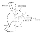
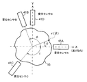
- FIG. 3 is a top view schematically showing the arrangement of the turntable 16 and the displacement sensors 41A, 41B, 41C.
- the displacement sensor 41A is arranged in the X direction, and the displacement sensors 41B and 41C are arranged to make an angle ⁇ , (2 ⁇ ) with respect to the displacement sensor 41A ( ⁇ , ⁇ > 0).
- the roundness error of the measurement target cylindrical surface 16A can be expressed as r ( ⁇ ) using a polar coordinate system.
- the roundness error (hereinafter also referred to as roundness error data) r ( ⁇ ) can be expressed as an error from a perfect circle having a reference radius r 0 .
- the spindle motor 17 is rotated, and the radial displacement of the measured cylindrical surface (side surface of the turntable) 16A is measured.
- Radial displacement data S A ( ⁇ ), S B ( ⁇ ), and S C ( ⁇ ) from the displacement sensors 41A, 41B, and 41C (the direction away from the sensor is positive) are sent to the rotational shake calculator 43.
- the pulse from the rotary encoder 46 is sampled and converted into digital / analog (D / A). At this time, processing such as filtering and averaging may be performed as necessary.
- X and Y rotational vibration data x ( ⁇ ) and y ( ⁇ ) are obtained by the following calculation.
- the roundness error data r ( ⁇ ) does not include the first-order Fourier component, that is, the eccentric component of the turntable side surface 16A.
- the calculated rotational runouts x ( ⁇ ) and y ( ⁇ ) include the eccentric component of the turntable side surface 16A. ing.
- the eccentricity of the turntable side surface 16A does not correspond to the eccentricity of the substrate to be drawn, but is merely the eccentricity of the cylindrical surface to be measured. A concentric circle eccentric to the center of rotation is recorded.
- the eccentricity of the side surface of the turntable is usually in the sub-micrometer to micrometer even if precise mounting adjustment is performed. It is about a level. Therefore, when the recording position correction is performed using the above-described rotational shakes x ( ⁇ ) and y ( ⁇ ), the exposure beam is made larger than necessary to correct the recording position of the eccentric component on the side surface of the turntable that is not necessary. Will be deflected. Such a large deflection of the electron beam causes an increase in the aberration of the electron beam, which is disadvantageous for forming a fine pattern.
- the beam irradiation position adjustment device also has a wide beam deflection range on the micrometer level in order to correct the nanometer level rotational shake, which is the original purpose, and the S / N ratio of the beam deflection signal. Is not preferable.
- the rotational shake correction system in the present invention has a configuration that reduces the amplitude of rotational shake correction by using rotational shake data that does not include an eccentric component.
- FIG. 4 shows a flow chart for calculating shape data in the recording apparatus which is Embodiment 1 of the present invention.
- radial displacement data S A ( ⁇ ), S B ( ⁇ ), S C ( ⁇ ) of the turntable side surface 16A are taken in by the displacement sensors 41A, 41B, 41C, respectively.
- the rotational shake calculator 43 calculates the roundness from the radial displacement data S A ( ⁇ ), S B ( ⁇ ), S C ( ⁇ ) by the three-point roundness measurement method, and calculates roundness error data r. ( ⁇ ) is set (step S22).
- the roundness error data r ( ⁇ ) obtained by the three-point roundness measurement does not include a first-order Fourier component, that is, an eccentric component.
- eccentricity data e ( ⁇ ) is calculated (step S22).
- the eccentricity data e ( ⁇ ) is obtained, for example, by performing Fourier analysis on radial shake data of the displacement sensor.
- the eccentric data e ( ⁇ ) can be obtained by performing Fourier transform on the sampled radial shake data S A ( ⁇ ), extracting only the primary component, and performing inverse Fourier transform.
- the eccentricity data e ( ⁇ ) is added to the calculated roundness error data r ( ⁇ ) to calculate the shape data f ( ⁇ ) (step S23).
- 5, 6 and 7 show waveform examples of roundness error data r ( ⁇ ), eccentricity data e ( ⁇ ) and calculated shape data f ( ⁇ ), respectively.
- the shape data f ( ⁇ ) obtained in this way is stored in a memory such as a RAM provided in the rotational shake calculator 43 or the like.
- the shape data f ( ⁇ ) is stored in a memory (RAM) 48.
- the data is supplied to the subtracter 49 and the shape data f ( ⁇ ) is subtracted.
- the rotational shake calculator 43 performs the above-described calculation such as subtraction by high-speed processing means such as a DSP (Digital Signal Processor).
- high-speed processing means such as a DSP (Digital Signal Processor).
- the two-dimensional rotational shake components x f ( ⁇ ) and y f ( ⁇ ) in the X and Y directions are calculated at high speed in real time.
- the waveform data x f ( ⁇ ), y f ( ⁇ ) obtained in this way is supplied to the controller 30.
- the controller 30 controls the beam deflection unit 33 based on the calculated rotational shake data x f ( ⁇ ), y f ( ⁇ ), and adjusts (corrects) the irradiation position of the electron beam (EB) in real time. That is, the recording position is corrected by displacing the irradiation position of the exposure beam (electron beam) according to the rotational shake signal.
- the rotational shake data x f ( ⁇ ), y f ( ⁇ ) does not include an eccentric component. Therefore, the deflection range of the beam irradiation position adjusting device can be reduced. As a result, highly accurate concentric and spiral pattern recording can be realized while suppressing the influence of rotational shake without causing deterioration of the drawing pattern due to beam deflection aberration or deflection noise.
- the installation angle of one of the displacement sensors (referred to as sensor A) coincide with the feed direction of the feed stage (X stage) (see FIG. 3). That is, when the disc master is exposed, it is the rotational shake in the radial direction of the turntable and the feed direction of the stage that actually affects the track roundness error. Therefore, by installing one of the three displacement sensors (sensor A) in the stage feed direction, the rotational shake in the stage feed direction can be obtained by simple subtraction as shown in the following equation. There is an advantage that the processing becomes simple and correction in real time becomes easy.
- FIG. 9 shows an example of measured radial displacement data (for example, S A ( ⁇ )).
- the measured radial displacement amplitude is on the order of sub-micrometers to micrometers (see FIG. 8).
- the amplitude of the rotational shake that does not include such an eccentric component is on the order of several tens of nanometers, and it can be seen that the deflection range for beam irradiation position correction can be extremely small by using the rotational shake data.
- the shape data f is obtained by adding the eccentricity data e ( ⁇ ) to the roundness error data r ( ⁇ ) calculated based on the principle of the three-point method roundness measurement. ( ⁇ ). Then, rotational shake data is calculated by calculating each real-time radial displacement data to be measured and the shape data f ( ⁇ ). Since the beam irradiation position adjustment is performed based on the rotational shake data that does not include the eccentric component, the deflection range of the position adjustment correction can be reduced, and highly accurate concentric circle and spiral pattern recording can be realized.
- the displacement sensors 41A to 41C having sub-nanometer measurement sensitivity are used.
- the displacement sensors 41A to 41C are arranged so as not to cause an error in the sensor mounting height (radial displacement measurement height).
- An adjustment mechanism for adjusting the position (height) may be added. For example, when the controller 30 acquires the shape data f ( ⁇ ) by the controller 30, the height adjusting mechanism positions (displaces) the displacement sensors 41A to 41C so that the error of the shape data f ( ⁇ ) is within a predetermined range. Adjust.
- the arrangement direction of the displacement sensor is not limited to that shown in FIG. 3 and may be any direction. However, depending on the combination of the relative angles ⁇ and ⁇ of the displacement sensors 41A to 41C, the calculation diverges and a Fourier series component that cannot be detected appears. Therefore, it is set at a relative angle that can detect all Fourier components up to the highest order. It is desirable to do.
- the rotational shake component in the X direction that is the radial direction of the turntable 16 (substrate 15) and the feed direction of the stage that actually affects the track roundness error. It is. Therefore, as described above, it is desirable that one of the three displacement sensors 41A to 41C be installed in the X direction (feed direction). In this case, since simple subtraction is sufficient for the X direction, there is an advantage that the arithmetic processing at the time of correction is simplified.
- four displacement sensors 41A to 41D may be used, and two of them may be installed in the X direction (displacement sensor 41A) and the Y direction (displacement sensor 41D).
- the remaining two units are arranged at an angle at which the calculation does not diverge in the range up to the required Fourier order in the calculation of the three-point roundness measurement.
- the shape data f ( ⁇ ) acquired in advance and stored in the memory (RAM) 48 is used to obtain rotational shake data x f ( ⁇ ), y f ( ⁇ ) to obtain an exposure beam.
- shape data may be calculated in real time (real time), and the irradiation position may be adjusted in real time (real time). That is, the shape data f ( ⁇ ) at the time of recording (exposure) when the substrate is irradiated with an electron beam is calculated, and the rotational shake data x f ( ⁇ ), y f ( ⁇ ) is calculated using the shape waveform data r ( ⁇ ). ) May be calculated in real time (real time) to adjust the irradiation position of the electron beam.
- the shape data f ( ⁇ ) may be updated while calculating the shape data in real time (real time). That is, for example, as shown in FIG. 12, the shape data calculation unit 43A calculates shape data f ( ⁇ ) in real time during exposure and supplies it to the averaging processing unit 50.
- the averaging processing unit 50 sequentially updates the shape data f ( ⁇ ). For example, the moving average calculation of the shape data f ( ⁇ ) for a plurality of rotations is performed, and the shape data f ( ⁇ ) stored in the memory (RAM) 48 is appropriately updated with the moving average shape waveform data. For example, the averaging processing unit 50 controls to update the stored shape data f ( ⁇ ) every rotation.
- the rotational shake calculator 43 calculates rotational shake data x f ( ⁇ ), y f ( ⁇ ) using the updated average shape data f ( ⁇ ) in real time during exposure. And supplied to the controller 30.
- the shape data f ( ⁇ ) By configuring the shape data f ( ⁇ ) to be updated in real time in this way, the measurement height position changes due to the thermal expansion of the turntable or spindle, etc., and the measurement table shape waveform of the turntable changes. Since no error occurs in the shake calculation result, it is possible to cope with long-time exposure.
Landscapes
- Engineering & Computer Science (AREA)
- Physics & Mathematics (AREA)
- Plasma & Fusion (AREA)
- Manufacturing & Machinery (AREA)
- Manufacturing Optical Record Carriers (AREA)
- Manufacturing Of Magnetic Record Carriers (AREA)
- Electron Beam Exposure (AREA)
Abstract
Description
図1は、本発明の実施例である電子ビーム記録装置10の構成を模式的に示すブロック図である。電子ビーム記録装置10は、電子ビームを用い、ハードディスク製造用の原盤を作成するディスクマスタリング装置である。
次に、かかる電子ビーム記録装置10において、回転振れを検知・演算し、当該回転振れに基づいてビーム照射位置を調整する構成及び動作について、図面を参照して詳細に説明する。
y(θ)=-r(θ)-SA(θ)
xf(θ)= [{SB(θ)+f(θ-φ)}cosτ-{ Sc(θ)+ f(θ+τ)}cosφ]/sin(θ+τ) (1)
yf(θ)= -f(θ)-SA(θ) (2)
と表される。
15 基板
16 ターンテーブル
17 スピンドルモータ
18 送りステージ
25 ビーム偏向電極
30 コントローラ
33 ビーム偏向部
37 ステージ駆動部
41 変位検知装置
41A,41B,41C,41D 変位センサ
43 回転振れ演算器
43A 形状データ演算部
45 モータ制御回路
46 ロータリーエンコーダ
48 メモリ
49 減算器
50 平均化処理部
Claims (17)
- 基板を載置したターンテーブルを回転させつつ基板上に形成されたレジスト層に記録信号に応じて電子ビームを照射することにより前記レジスト層に潜像を形成する電子ビーム記録装置であって、
前記ターンテーブルのラジアル方向に互いに異なる角度で配され、前記ターンテーブルの回転側面のラジアル方向における変位を検知する少なくとも3つの変位センサを有する変位検知器と、
前記ターンテーブルの真円度誤差及び前記ターンテーブルの偏心成分に基づいて形状データを算出する形状算出器と、
前記形状データを格納するメモリと、
前記ターンテーブルの回転時における前記変位センサからの検知変位及び前記形状データに基づいて、前記ターンテーブルの偏心成分を含まない回転振れを算出する回転振れ演算器と、
前記回転振れに基づいて前記電子ビームの照射位置を調整するビーム照射位置調整器と、を有することを特徴とする電子ビーム記録装置。 - 前記ターンテーブルの偏心成分は、前記変位センサのラジアル方向における変位に基づいて算出することを特徴とする請求項1に記載の電子ビーム記録装置。
- 前記真円度誤差は、前記変位検知器の検出する検知変位に基づいて、3点法真円度測定法により算出されることを特徴とする請求項1に記載の電子ビーム記録装置。
- 前記形状算出器は、前記変位センサの検知変位に基づいて、前記ターンテーブルの回転角度に対する前記ターンテーブル側面の前記偏心成分を算出する偏心算出器を有することを特徴とする請求項1ないし3のいずれか1に記載の電子ビーム記録装置。
- 前記形状算出器は、前記真円度誤差算出器で算出した真円度誤差と、前記偏心算出器で算出したターンテーブル側面の偏心成分とを加算して前記形状データを算出することを特徴とする請求項1ないし4のいずれか1に記載の電子ビーム記録装置。
- 前記回転振れ演算器は、前記形状データ及び前記ターンテーブルの回転時における前記前記変位センサからの検知変位と、に基づいて前記ターンテーブルの回転振れを算出することを特徴とする請求項1に記載の電子ビーム記録装置。
- 前記回転振れ演算器は、前記変位センサからの検知変位から、あらかじめ前記偏心算出器で算出したターンテーブル側面の偏心成分をそれぞれ減算した変位データ及び前記真円度誤差に基づいて、前記ターンテーブルの回転振れを算出することを特徴とする請求項1ないし4のいずれか1に記載の電子ビーム記録装置。
- 前記回転振れ演算器は、前記変位センサからの検知変位及び前記真円度誤差に基づいて算出された前記ターンテーブルの回転振れから、前記偏心算出器で算出したターンテーブル側面の偏心成分を減算して回転振れを算出することを特徴とする請求項1ないし4のいずれか1に記載の電子ビーム記録装置。
- 前記ターンテーブルを前記ターンテーブルのラジアル方向に移送する送りステージを有し、前記変位センサのうち1つは当該移送方向に配されていることを特徴とする請求項1ないし8のいずれか1に記載の電子ビーム記録装置。
- 前記変位検知器は4つの変位センサを有し、前記4つの変位センサのうちの1つは前記移送方向に配された変位センサと直交する方向に配されていることを特徴とする請求項9に記載の電子ビーム記録装置。
- 前記回転振れ演算器は、前記基板への電子ビーム記録に先立って算出された既算出形状データに基づいて前記回転振れを算出することを特徴とする請求項1ないし10のいずれか1に記載の電子ビーム記録装置。
- 前記ターンテーブルを複数回回転させて前記形状データを平均化する平均化処理部を有し、前記回転振れ算出部は当該平均化された形状データに基づいて前記回転振れデータを算出することを特徴とする請求項1ないし11のいずれか1に記載の電子ビーム記録装置。
- 前記形状データを更新する形状データ更新部をさらに有することを特徴とする請求項1ないし12のいずれか1に記載の電子ビーム記録装置。
- 基板を載置したターンテーブルを回転させつつ基板上に記録信号に応じて電子ビームを照射することにより記録をなす電子ビーム記録装置であって、
前記ターンテーブルのラジアル方向への変位情報を検知する変位センサと、
前記変位情報に基づいて前記ターンテーブルの偏心に起因する偏心成分を取得する偏心成分取得手段と、
前記変位情報から前記偏心成分を減算して回転振れ情報を生成する回転振れ情報生成手段と、
前記回転振れ情報に基づいて前記電子ビームの照射位置を調整するビーム照射位置調整器と、を有することを特徴とする電子ビーム記録装置。 - 前記回転振れ情報生成手段は、前記ターンテーブルの形状成分と前記偏心成分とに基づいて前記回転振れ情報を生成することを特徴とする請求項14に記載の電子ビーム記録装置。
- 前記ターンテーブルの真円度誤差情報を取得する誤差情報手段を有し、
前記回転振れ情報生成手段は、前記真円度誤差情報及び前記偏心成分に基づいて前記回転振れ情報を生成することを特徴とする請求項15に記載の電子ビーム記録装置。 - 基板を載置したターンテーブルを回転させつつ基板上に記録信号に応じて電子ビームを照射することにより記録をなす電子ビーム記録装置であって、
前記ターンテーブルのラジアル方向への変位である変位データを取得する変位データ取得手段と、
前記ターンテーブルの偏心に起因する偏心成分を取得する偏心成分取得手段と、
前記変位データから前記偏心成分を取り除いた回転振れ情報を取得する回転振れ情報取得手段と、
前記回転振れ情報に基づいて前記電子ビームの照射位置を調整するビーム照射位置調整器と、を有することを特徴とする電子ビーム記録装置。
Priority Applications (3)
| Application Number | Priority Date | Filing Date | Title |
|---|---|---|---|
| US13/498,544 US20120181445A1 (en) | 2009-09-28 | 2009-09-28 | Electron beam recording apparatus |
| JP2011532877A JP5433011B2 (ja) | 2009-09-28 | 2009-09-28 | 電子ビーム記録装置 |
| PCT/JP2009/066791 WO2011036801A1 (ja) | 2009-09-28 | 2009-09-28 | 電子ビーム記録装置 |
Applications Claiming Priority (1)
| Application Number | Priority Date | Filing Date | Title |
|---|---|---|---|
| PCT/JP2009/066791 WO2011036801A1 (ja) | 2009-09-28 | 2009-09-28 | 電子ビーム記録装置 |
Publications (1)
| Publication Number | Publication Date |
|---|---|
| WO2011036801A1 true WO2011036801A1 (ja) | 2011-03-31 |
Family
ID=43795571
Family Applications (1)
| Application Number | Title | Priority Date | Filing Date |
|---|---|---|---|
| PCT/JP2009/066791 Ceased WO2011036801A1 (ja) | 2009-09-28 | 2009-09-28 | 電子ビーム記録装置 |
Country Status (3)
| Country | Link |
|---|---|
| US (1) | US20120181445A1 (ja) |
| JP (1) | JP5433011B2 (ja) |
| WO (1) | WO2011036801A1 (ja) |
Families Citing this family (2)
| Publication number | Priority date | Publication date | Assignee | Title |
|---|---|---|---|---|
| JP6876470B2 (ja) * | 2017-03-07 | 2021-05-26 | 東京エレクトロン株式会社 | ワーク加工装置、ワーク加工方法、プログラム及びコンピュータ記憶媒体 |
| CN112186976B (zh) * | 2020-08-07 | 2022-01-28 | 山东大学 | 一种无轴承磁悬浮电机转子径向位置检测装置及控制方法 |
Citations (5)
| Publication number | Priority date | Publication date | Assignee | Title |
|---|---|---|---|---|
| JPH09190651A (ja) * | 1995-03-10 | 1997-07-22 | Toshiba Corp | 光ディスク原盤露光装置及び非同期振れ量補正装置 |
| JP2003059120A (ja) * | 2001-08-08 | 2003-02-28 | Tosoh Corp | レジスト原盤の偏芯除去方法及びレジスト原盤露光装置 |
| JP2003272248A (ja) * | 2002-03-19 | 2003-09-26 | Ricoh Co Ltd | 光ディスク原盤露光装置および非同期回転振れ量検出方法 |
| JP2007095302A (ja) * | 2006-11-20 | 2007-04-12 | Ricoh Co Ltd | 光ディスク原盤露光装置および光ディスク原盤露光方法、並びに回転振れ量検出方法 |
| WO2007111260A1 (ja) * | 2006-03-24 | 2007-10-04 | Pioneer Corporation | ビーム記録装置及びビーム調整方法 |
Family Cites Families (6)
| Publication number | Priority date | Publication date | Assignee | Title |
|---|---|---|---|---|
| US6225012B1 (en) * | 1994-02-22 | 2001-05-01 | Nikon Corporation | Method for positioning substrate |
| JP2002342988A (ja) * | 2001-05-18 | 2002-11-29 | Ricoh Co Ltd | 光ディスク原盤露光装置 |
| JP2003317285A (ja) * | 2002-04-25 | 2003-11-07 | Ricoh Co Ltd | 光ディスク原盤露光装置および光ディスク原盤露光方法、並びに回転振れ検出方法 |
| JP2004079056A (ja) * | 2002-08-14 | 2004-03-11 | Ricoh Co Ltd | 光ディスク原盤露光装置 |
| JP4559984B2 (ja) * | 2006-03-10 | 2010-10-13 | 株式会社リコー | 光ディスク原盤露光装置 |
| JP2010072180A (ja) * | 2008-09-17 | 2010-04-02 | Ricoh Co Ltd | 補正システム及び電子線描画装置 |
-
2009
- 2009-09-28 US US13/498,544 patent/US20120181445A1/en not_active Abandoned
- 2009-09-28 JP JP2011532877A patent/JP5433011B2/ja not_active Expired - Fee Related
- 2009-09-28 WO PCT/JP2009/066791 patent/WO2011036801A1/ja not_active Ceased
Patent Citations (5)
| Publication number | Priority date | Publication date | Assignee | Title |
|---|---|---|---|---|
| JPH09190651A (ja) * | 1995-03-10 | 1997-07-22 | Toshiba Corp | 光ディスク原盤露光装置及び非同期振れ量補正装置 |
| JP2003059120A (ja) * | 2001-08-08 | 2003-02-28 | Tosoh Corp | レジスト原盤の偏芯除去方法及びレジスト原盤露光装置 |
| JP2003272248A (ja) * | 2002-03-19 | 2003-09-26 | Ricoh Co Ltd | 光ディスク原盤露光装置および非同期回転振れ量検出方法 |
| WO2007111260A1 (ja) * | 2006-03-24 | 2007-10-04 | Pioneer Corporation | ビーム記録装置及びビーム調整方法 |
| JP2007095302A (ja) * | 2006-11-20 | 2007-04-12 | Ricoh Co Ltd | 光ディスク原盤露光装置および光ディスク原盤露光方法、並びに回転振れ量検出方法 |
Also Published As
| Publication number | Publication date |
|---|---|
| JP5433011B2 (ja) | 2014-03-05 |
| JPWO2011036801A1 (ja) | 2013-02-14 |
| US20120181445A1 (en) | 2012-07-19 |
Similar Documents
| Publication | Publication Date | Title |
|---|---|---|
| US7875866B2 (en) | Beam recording apparatus and beam adjustment method | |
| US6650611B1 (en) | Master disc manufacturing apparatus | |
| JP5433011B2 (ja) | 電子ビーム記録装置 | |
| WO2006070555A1 (ja) | ビーム記録方法及び装置 | |
| JP4216313B2 (ja) | 電子ビーム位置変動測定方法、電子ビーム位置変動測定装置、電子ビーム記録装置 | |
| JP5087679B2 (ja) | 電子ビーム装置 | |
| US7298678B2 (en) | Rotating recorder with dual encoder arrangement having eccentricity compensation | |
| JPWO2007111261A1 (ja) | 電子ビーム記録装置及びビーム調整方法 | |
| JP2010072180A (ja) | 補正システム及び電子線描画装置 | |
| JP5166400B2 (ja) | ビーム描画装置 | |
| JP4580592B2 (ja) | 光ディスク原盤露光装置 | |
| JP2008140419A (ja) | 電子ビームマスタリング装置及び回転ムラ補正方法 | |
| US7280935B2 (en) | Dual sensor assemblies for positional output feedback | |
| Kitahara et al. | Electron beam recorder for patterned media mastering | |
| JP3986867B2 (ja) | ディスク原盤製造装置 | |
| JP2010117507A (ja) | 電子ビーム記録装置 | |
| US20100102254A1 (en) | Electron beam apparatus | |
| JP4081878B2 (ja) | 光ディスク原盤記録装置および光ディスク原盤の位置決め方法 | |
| JP2009164323A (ja) | 電子線描画装置及び電子線描画方法 | |
| JP2008203555A (ja) | 露光ビーム照射装置 | |
| JP2010205326A (ja) | 電子線描画装置、ステージ位置偏差算出方法及びパターン描画方法 | |
| JP2006078591A (ja) | 電子ビーム露光装置 | |
| JP2009175302A (ja) | 電子線描画装置、移動ステージ変動量算出方法及びパターン描画方法 | |
| JP2011238603A (ja) | パターン検査装置およびパターン検査方法 | |
| JP2009151845A (ja) | 電子線描画装置及びトレイ |
Legal Events
| Date | Code | Title | Description |
|---|---|---|---|
| 121 | Ep: the epo has been informed by wipo that ep was designated in this application |
Ref document number: 09849832 Country of ref document: EP Kind code of ref document: A1 |
|
| WWE | Wipo information: entry into national phase |
Ref document number: 2011532877 Country of ref document: JP |
|
| WWE | Wipo information: entry into national phase |
Ref document number: 13498544 Country of ref document: US |
|
| NENP | Non-entry into the national phase |
Ref country code: DE |
|
| 122 | Ep: pct application non-entry in european phase |
Ref document number: 09849832 Country of ref document: EP Kind code of ref document: A1 |