WO2011027766A1 - Joint de tuyau - Google Patents
Joint de tuyau Download PDFInfo
- Publication number
- WO2011027766A1 WO2011027766A1 PCT/JP2010/064887 JP2010064887W WO2011027766A1 WO 2011027766 A1 WO2011027766 A1 WO 2011027766A1 JP 2010064887 W JP2010064887 W JP 2010064887W WO 2011027766 A1 WO2011027766 A1 WO 2011027766A1
- Authority
- WO
- WIPO (PCT)
- Prior art keywords
- hose
- diameter
- peripheral surface
- nipple
- sleeve
- Prior art date
Links
Images

Classifications
-
- F—MECHANICAL ENGINEERING; LIGHTING; HEATING; WEAPONS; BLASTING
- F16—ENGINEERING ELEMENTS AND UNITS; GENERAL MEASURES FOR PRODUCING AND MAINTAINING EFFECTIVE FUNCTIONING OF MACHINES OR INSTALLATIONS; THERMAL INSULATION IN GENERAL
- F16L—PIPES; JOINTS OR FITTINGS FOR PIPES; SUPPORTS FOR PIPES, CABLES OR PROTECTIVE TUBING; MEANS FOR THERMAL INSULATION IN GENERAL
- F16L33/00—Arrangements for connecting hoses to rigid members; Rigid hose connectors, i.e. single members engaging both hoses
- F16L33/22—Arrangements for connecting hoses to rigid members; Rigid hose connectors, i.e. single members engaging both hoses with means not mentioned in the preceding groups for gripping the hose between inner and outer parts
- F16L33/223—Arrangements for connecting hoses to rigid members; Rigid hose connectors, i.e. single members engaging both hoses with means not mentioned in the preceding groups for gripping the hose between inner and outer parts the sealing surfaces being pressed together by means of a member, e.g. a swivel nut, screwed on or into one of the joint parts
- F16L33/224—Arrangements for connecting hoses to rigid members; Rigid hose connectors, i.e. single members engaging both hoses with means not mentioned in the preceding groups for gripping the hose between inner and outer parts the sealing surfaces being pressed together by means of a member, e.g. a swivel nut, screwed on or into one of the joint parts a clamping ring being arranged between the threaded member and the connecting member
Definitions
- the present invention relates to a hose coupling used for piping connection of a soft and deformable hose such as silicone rubber. More specifically, the present invention relates to a hose joint in which a hose is inserted along the outer peripheral surface of a nipple and the inner peripheral surface of the hose is in close contact with the outer peripheral surface of the nipple by axial movement of a fastener provided on the outer side.
- a front connected between a nut connected to a second joint configured as a nipple and an inner peripheral surface of a female screw of the nut and an outer peripheral surface of a hose tip The inner side of the hose end in a state of being connected to the ring, the back ring interposed between the rear end inner peripheral surface of the nut and the outer peripheral surface of the hose spaced apart from the front ring by a predetermined distance, and the second joint
- an insert sleeve which is fitted into a circumferential surface and which holds an inner and outer peripheral surface on the end of the hose together with a front ring or a buckling (see, for example, Patent Document 1).
- the buckling is drawn to the front ring side, and the outer periphery of the hose externally fitted on the annular convex portion of the insert sleeve or the both curved slopes is the front ring.
- a portion which is radially expanded and deformed by the annular convex portion is clamped in the axial direction by the front ring or the buckling.
- the fitting cylinder outer periphery of the insert sleeve is fluid-tightly fitted to the large diameter stepped fitting hole of the second joint via the O ring,
- the fluid that has entered the gap between the communication hole of the insert sleeve and the communication hole of the second joint is also in contact with (is in contact with) the O-ring, which tends to be unsanitary, resulting in a problem that the application is limited. Therefore, the insert sleeve and the second joint are integrated in advance, the hose is inserted along the annular convex portion of the insert sleeve, and the end portion of the hose is inserted into the front ring which stands by at the fixed position.
- An object of the present invention is to address such problems, and to stabilize the pressing position of the tip of the hose to enhance the sealing performance and the detachment strength between the outer peripheral surface of the nipple and the hose, and the outer periphery of the nipple.
- the object of the invention is to further improve the sealing property and removal strength between the surface and the hose, to reliably clamp the hose in the axial direction and the radial direction, and to reliably insert the hose to a fixed position.
- the hose is inserted along the outer peripheral surface of the nipple, and the inner peripheral surface of the hose is the outer periphery of the nipple by the axial movement of the clamp provided on the outer side.
- a radially expandable resiliently contracting sleeve which is provided opposite to the diameter reducing surface of the bulged portion, and which is formed on the inner side of the fastener against the outer peripheral surface of the expandable sleeve, and which is used for the nipple
- the expansion sleeve is formed so as to gradually increase in diameter in the direction opposite to the hose insertion direction, and the axially extending slot is cut out to be elastically deformable in the radial direction
- an annular convex portion is formed opposite to the outer peripheral surface of the hose, and the inner diameter of the annular convex portion is reduced on the diameter reducing surface of the bulging portion when the hose is inserted.
- the diameter reducing surface of the bulging portion It is set to be smaller than the outer diameter of the hose inserted along the.
- the inner peripheral surface of the clamp is a separate body or a pressing cylinder formed to face the enlarged diameter surface of the bulging part as the clamp moves in the axial direction. Integrally provided, facing an annular space formed between a hose insertion direction side end surface of the pressing cylinder and an opposite hose insertion direction side end surface of the expansion / contraction sleeve in a tightening state by axial movement of the tightening tool.
- the present invention is characterized in that the engaging recess is formed.
- annular flange portion facing the tip end surface of the hose is formed at the end portion in the hose insertion direction of the expansion and contraction sleeve so as to face the back side outer peripheral surface of the nipple.
- the present invention having the features described above sets the inner diameter of the inlet facing the diameter reducing surface of the expansion sleeve larger than the outer diameter of the hose inserted along the diameter reducing surface of the bulging portion when the hose is inserted.
- the tip end of the hose can be smoothly inserted between the expansion and contraction sleeve and the reduced diameter surface without inserting into the inlet of the expansion and contraction sleeve and can be inserted to a fixed position.
- the inner diameter of the inlet of the expansion sleeve is set smaller than the outer diameter of the hose inserted along the reduced diameter surface of the bulge.
- the hose is sandwiched between the inlet of the expansion sleeve and the reduced diameter surface of the nipple, so the push-in position of the hose tip is stabilized to improve the sealing performance and removal strength between the outer peripheral surface of the nipple and the hose. it can.
- the workability of the hose connection is improved, and the hose connection operation can be performed easily and in a short time and reliably for anyone.
- no liquid pool or liquid contact with the O-ring occurs in the middle of the communication passage formed along the inner circumferential surface of the nipple. Yes, regardless of the type and application of the fluid, the degree of freedom is increased and usability is good.
- the expansion sleeve is formed so as to gradually increase in diameter in the direction opposite to the hose insertion direction, and a slot extending in the axial direction is cut out to be elastically deformable in the radial direction, and the expansion and contraction
- An annular convex portion is formed at the inlet portion of the sleeve to face the outer peripheral surface of the hose, and the inner diameter of the annular convex portion is inserted along the diameter reducing surface of the bulging portion when the hose is inserted.
- the expansion sleeve is set to be larger than the outer diameter of the hose, and when the expansion sleeve is pressed by the pressing surface along with the axial movement of the fastener, the expansion sleeve is inserted along the reduced diameter surface of the bulging portion.
- the tip of the hose does not abut the annular convex portion which is the inlet of the expansion sleeve during insertion of the hose, and the inner periphery of the expansion sleeve Face and shrinkage
- the expansion and contraction sleeve is reduced in diameter and the inner peripheral surface and the back side outer periphery of the nipple
- the annular convex part bites into the outer peripheral surface of the hose and is further inserted between the diameter reducing surface of the nipple and the outer surface of the nipple. Sealability and pull-out strength can be further improved.
- a pressing cylindrical portion formed separately from or integrally with the inner peripheral surface of the clamp so as to face the enlarged diameter surface of the bulging portion along with the axial movement of the clamp is provided,
- the engagement concave portion is opposed to the annular space formed between the hose insertion direction side end surface of the pressing cylinder and the non-hose insertion direction side end surface of the expansion sleeve in a tightened state by axial movement of the tool.
- the hose is radially interposed between the enlarged diameter surface of the bulging portion and the pressing cylinder by axial movement of the fastener, and at the same time the outer peripheral surface of the hose is the pressing cylinder.
- the outer peripheral surface of the hose that has been bulgingly deformed toward the engagement recess through the annular space formed between the end face of the hose in the direction of insertion of the hose and the end face of the expansion sleeve in the direction of inserting the hose. Is in close contact and press-contact along the engagement recess. It is possible to reliably sandwich the scan in the axial and radial directions. As a result, even if the hose is particularly soft and easily deformed like, for example, a silicone hose, the deformation of the hose is used to improve the sealing performance and the removal strength, so that the hose can be reliably prevented from dropping off.
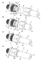
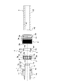
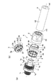
- the longitudinal cross-sectional view which shows the hose coupling which concerns on embodiment of this invention (a) shows the state before hose insertion, (b) shows the state after hose insertion, (c) is the time of a movement start of a fastener. (D) shows the state after the end of movement of the fastener. It is the same perspective view, (a) shows the state before hose insertion, (b) shows the state after hose insertion, (c) shows the state at the time of movement of a clamp, (d) shows the clamp It shows the state after the end of the movement of the tool. It is a vertical front view which shows the disassembled state of the hose coupling which concerns on embodiment of this invention. It is the same perspective view, (a) has shown the whole decomposition
- the nipple 1 into which the connecting end of the flexible hose H is inserted, and the axial reciprocation with respect to this nipple 1 A clamp 2 provided and an expansion / contraction sleeve 3 disposed on the outer peripheral surface of the nipple 1 via the connection end of the hose H, and after the connection end of the hose H is inserted into the outer peripheral surface of the nipple 1,
- the inner peripheral surface H1 of the connection end of the hose H is the nipple 1 by moving the clamp 2 in the axial direction, for example, the insertion direction of the hose H (hereinafter referred to as the hose insertion direction) to reduce the diameter of the expansion sleeve 3.
- the hose H is closely connected to the outer peripheral surface so as not to be pulled out.
- the nipple 1 is formed in a cylindrical shape having an outer diameter substantially the same as or slightly larger than the inner diameter of the hose H, for example, with a hard material such as a metal such as brass or hard synthetic resin Can be formed into a cylindrical shape with a thin wall thickness by pressing or other forming a plate material made of a rigid material, and the diameter is gradually enlarged in the hose insertion direction on the outer peripheral surface of the plate from the largest diameter portion An annular bulging portion 1a is formed to be gradually reduced in diameter.
- a hard material such as a metal such as brass or hard synthetic resin
- the annular bulging portion 1a has an enlarged diameter surface 1a1 which gradually expands in diameter in the hose insertion direction from the tip edge 1b in a direction opposite to the hose insertion direction of the nipple 1 (hereinafter referred to as reverse insertion direction)
- the diameter reducing surface 1a2 gradually decreasing in diameter from the diameter portion in the hose insertion direction is continuously disposed, and in the example shown in FIGS. As an example, it is also possible to incline in a curved surface.
- a back side outer peripheral surface 1c having the same diameter as the minimum diameter portion of the reduced diameter surface 1a is formed in a predetermined length in the hose insertion direction on the rear side of the reduced diameter surface 1a2 of the bulging portion 1a in the hose insertion direction.
- a reverse tapered surface 1d gradually expanding in diameter toward the tip, and in the example shown in FIG. 1 (d), the nipple 1 is tightened by the fastener 2 described later.
- the hose H is pushed inward by the pressing cylinder 4 by projecting the pressing cylinder 4 which will be described later than the tip edge 1 b of the second embodiment so that the inner end portion thereof is continuous with the reverse tapered surface 1 d of the nipple 1. It is preferable to arrange.
- an annular step 1e that protrudes substantially perpendicularly from the back side outer peripheral surface 1c is integrally formed.
- a slide means 1f is formed to support the clamp 2 to be described later reciprocably in the hose insertion direction and in the direction opposite to the hose insertion direction.
- flat portions on which tools etc. engage are made circumferentially on the outer peripheral surface of the nipple 1 at appropriate intervals as in the example shown in FIGS. It is preferable to form a plurality of projections, or to form an uneven portion such as a knurled.
- the fastener 2 is formed of a material similar to or different from the nipple 1 and formed in a substantially cylindrical shape having an inner diameter larger than the outer diameter of the hose H, and engaged with the slide means 1f of the nipple 1 on the inner peripheral surface thereof.
- a slide means 2a is formed to support reciprocably in the hose insertion direction and the counter insertion direction.
- a screw is used to relatively reciprocate in the hose insertion direction and the counter insertion direction by rotating the clamp 2 relative to the nipple 1. It is preferable to form.
- the sleeve diameter reducing means it is preferable to directly form on the inner peripheral surface of the fastener 2 a pressing surface portion 2b which is inclined in a tapered shape in which the inner diameter gradually decreases in the counter-insertion direction.
- a pressing sleeve is rotatably provided on the inner side (inner periphery) of the fastener 2 and the inner circumferential surface of the pressing sleeve is opposed to the outer circumferential surface of the cylindrical expansion / contraction portion 3e of the expansion sleeve 3 described later. It is also possible to use a tapered pressing surface portion whose inner diameter gradually decreases in diameter toward the opposite insertion direction.
- Another pressing cylinder 4 is formed to face the enlarged diameter surface 1a1 of the bulging portion 1a as the clamp 2 moves in the axial direction.
- non-slip means 2d for rotational operation on the outer peripheral surface of the clamp 2 for example, as in the examples shown in FIGS. It is preferable to form a plurality of projections, or to form an uneven portion such as a knurled.
- the expansion / contraction sleeve 3 is formed in a substantially cylindrical shape, for example, of an elastically deformable material such as polyacetal resin or a synthetic resin excellent in slipperiness and heat resistance of the other surface, and inserted into the annular step 1e of the nipple 1 Thus, it is disposed to face the reduced diameter surface 1a2 of the nipple 1 and the back side outer peripheral surface 1c, and in particular, a portion on the opposite side of the hose insertion direction opposite to the reduced diameter surface 1a2 is used as the inlet 3a. Furthermore, as shown in FIGS.
- the expansion / contraction sleeve 3 undergoes a diameter expansion deformation at the time and before the insertion of the hose H, and at least the inner diameter of the inlet 3a It is set to be larger than the outer diameter of the hose H inserted along the reduced diameter surface 1a2 of 1a, and as shown in FIG. 1 (d), the pressing surface 2b is moved along with the axial movement of the fastener 2. When pressed, the diameter is reduced and the inner diameter of the inlet 3a is set to be smaller than the outer diameter of the hose H inserted along the reduced diameter surface 1a2 of the bulging portion 1a.
- the pressing cylinder 4 is separately or integrally provided on the inner peripheral surface of the fastener 2, the diameter-increased surface 1a1 of the bulging part 1a and the pressing cylinder 4 by axial movement of the fastener 2.
- the outer peripheral surface H2 of the hose H is inserted into the hose insertion direction side end surface (back end surface) 4a of the pressing cylinder 4 and the non-hose insertion of the expansion sleeve 3
- the outer peripheral surface H2 of the hose H which is bulgingly deformed toward the engagement recess 2c through the annular space S formed between the end surface (inlet side end surface) 3b and the engagement side Close contact and press along 2c.
- the expansion / contraction sleeve 3 is formed so as to gradually expand in diameter in the counter-insertion direction, and the axially extending slit 3c is cut out to be elastically deformable in the radial direction, and
- An annular convex portion is formed in the inlet portion 3a opposite to the outer peripheral surface H2 of the hose H, and the inner diameter of the annular convex portion is formed on the diameter-reduced surface 1a2 of the bulging portion 1a before and during insertion of the hose H.
- the diameter is set to be smaller than the outer diameter of the hose H inserted along the reduced diameter surface 1a2 of the portion 1a. That is, the inner diameter of the expansion sleeve 3 at the back in the hose insertion direction is set substantially the same as the outer diameter of the hose H inserted along the reduced diameter surface 1b2 of the bulging portion 1b, and the axial movement of the fastener 2 is achieved.
- the diameter of the expansion and contraction sleeve 3 is deformed and the inner peripheral surface 3d and the back outer periphery of the nipple 1 are reduced.
- the annular convex portion serving as the inlet 3 a thereof bites into the outer peripheral surface H 2 of the hose H and is further strongly sandwiched between the reduced diameter surface 1 a 2 of the nipple 1.
- the first embodiment can be used as the slide means 1f of the nipple 1
- the screw part is engraved, the inner screw part is cut as the slide means 2a of the clamp 2 opposed to this, the outer screw part 1f and the inner screw part 2a are screwed together, and the clamp 2 is fixed to the nipple 1
- the pressing surface portion 2b integrally formed on the inner peripheral surface of the fastener 2 presses the inlet portion 3a of the expansion and contraction sleeve 3 so as to reduce the diameter thereof.
- this expansion / contraction sleeve 3 is a cylinder having an annular convex portion to be the inlet portion 3a, an end face (inlet side end face) 3b opposite to the hose insertion direction and an inner circumferential surface 3d.
- a ring-shaped portion 3f formed integrally from the other end of the cylindrical portion 3e in the hose insertion direction toward the back side outer peripheral surface 1c of the nipple 1; While being used as an abutment surface of the tip end surface (cut surface) H3 of the hose H, a plurality of slits 3c are formed in the circumferential direction.
- one grit 3c1 is continued over the cylindrical expansion / contraction portion 3e and the annular collar portion 3f, but the other grit 3c2 is partial to the cylindrical expansion / contraction portion 3e or the annular collar portion 3f It is formed in.
- a stopper 3g opposed to the tip end edge 1h of the external thread to be the sliding means 1f of the nipple 1 is integrally protruded.
- the axial dimension from the stopper 3g to the annular flange 3f and the axial dimension from the tip end edge 1h of the external thread portion 1f of the nipple 1 to the annular step 1e are set in advance.
- the annular collar portion 3f of the expansion / contraction sleeve 3 is positioned to abut against the annular step 1e of the nipple 1
- the annular collar 3f is brought into contact with the annular step 1e of the nipple 1 only by looking at the positional relationship between the stopper 3g and the tip edge 1h of the external thread 1f, for example, the looseness between them. It can be determined whether or not it is correctly assembled.
- the hose H reaches the target position with the backlash between the stopper 3g and the tip edge 1h of the external thread 1f. It can be easily detected that the insertion has been made reliably, and the expansion and contraction sleeve 3 can be prevented from being deformed and broken with the insertion of the hose H.
- the separate ring to be the pressing cylinder portion 4 is formed by cutting the slit 4b extending along its entire axial length so as to be elastically deformable in the radial direction.
- the tapered surfaces 4d and 2e are formed on the outer peripheral surface 4c and / or the inner peripheral surface of the clamp 2 opposed thereto so as to press the separate ring 4 so as to reduce its diameter.
- the inner diameter in the state is set to be smaller than the outer diameter of the hose H inserted along the enlarged diameter surface 1a1 of the bulging portion 1a.
- connection portion 1i for connecting to a pipe connection port (not shown) of another device is continuously provided on the back side in the hose insertion direction with respect to the external screw portion formed as the slide means 1f of the nipple 1 .
- the connection portion 1i is formed with an outer thread corresponding thereto, and When an external screw is engraved on the outer peripheral surface of the pipe connection port, an internal screw corresponding to this is engraved.
- the nipple 1 is a cut product obtained by shaving a cylindrical material, for example, by cutting, and an external thread is cut as the connection portion 1i.
- the hose H is made of a soft material such as silicone rubber and a soft synthetic resin such as vinyl chloride, and it is preferable that the inner peripheral surface H1 and the outer peripheral surface H2 be flat.
- a specific example thereof is a laminated hose in which a plurality or a single synthetic resin blade (reinforcing yarn) is spirally embedded as an intermediate layer between the transparent or opaque outer layer and the inner layer, or an intermediate layer
- a braided reinforced hose in which a material is braided on the outer peripheral surface of a hose, a spiral reinforced hose in which a metal wire or a hard synthetic resin wire is embedded in a spiral shape, a flexible synthetic resin hose having a single layer structure, or the like is used.
- the hose H is inserted into a separate ring that becomes the clamp 2 and the pressing cylinder 4, and then the tip of the hose H is directed to the insertion space of the hose H and inserted along the bulging portion 1 a of the nipple 1 Start.
- the annular convex portion to be the inlet portion 3a of the expansion / contraction sleeve 3 is expanded and deformed so as to be larger than the outer diameter of the hose H inserted along the reduced diameter surface 1a2 of the expanded portion 1a. Therefore, the tip end of the hose H is smoothly inserted between the inner peripheral surface 3 d of the expansion / contraction sleeve 3 and the outer peripheral surface 1 c of the nipple 1 and the reduced diameter surface 1 a 2 without abutting the tip of the hose H As shown in FIG. 1 (b) and FIG.
- the hose H has a tip end surface H3 butting against the annular step 1e of the nipple 1 via the annular flange 3f of the expansion / contraction sleeve 3, further hose H Can not be inserted.
- the pressing surface portion 2b abuts against the cylindrical expansion / contraction portion 3e of the expansion sleeve 3 by the movement of the fastening tool 2 in the hose insertion direction.
- the diameter of the cylindrical expansion and contraction part 3e of the expansion and contraction sleeve 3 is reduced and deformed, and the hose H is sandwiched between the annular convex part to be the inlet part 3a and the reduced diameter surface 1a2 of the expansion part 1a.
- the annular convex portion to be the inlet 3a bites into the outer peripheral surface H2 of the hose H, and the other inner peripheral surface 3d is in pressure contact with the outer peripheral surface H2 of the hose H.
- the hose insertion direction side end face (rear side end face) 4a of the separate ring which becomes the pressing cylinder 4 and the outer hose H direction end face (inlet side end face) of the expansion sleeve 3 The outer peripheral surface H2 of the hose H which is bulgingly deformed toward the engaging recess 2c through the annular space S formed between 3b and the squeezed deformed H is in close contact and pressure contact along the engaging recess 2c.
- the hose H is soft and easily deformed like, for example, a silicone hose, the bite and expansion / contraction of the inner peripheral surface 4e of the separate ring which becomes the annular convex portion and the pressing cylinder 4 which becomes the inlet 3a.
- the outer peripheral surface H2 of the hose H expands by an amount corresponding to the compression, and the hose insertion direction side end face (back side end face) 4a of the ring and the non-hose insertion direction side of the expansion sleeve 3
- the hose H is firmly clamped in the axial direction and the radial direction because it is strongly sandwiched between the end face (inlet side end face) 3b, and the seal between the outer peripheral face of the nipple 1 and the hose H while stabilizing the pushing position of the hose tip. Sex and pull-out strength can be increased.
- the outer screw portion and the inner screw portion screwed with each other are formed as the slide means 1f, 2a for moving the clamp 2 in the axial direction with respect to the nipple 1, it is not limited thereto. As long as the fastener 2 can be moved in the axial direction with respect to the sleeve 3, a structure other than a screw may be used.
Landscapes
- Engineering & Computer Science (AREA)
- General Engineering & Computer Science (AREA)
- Mechanical Engineering (AREA)
- Joints That Cut Off Fluids, And Hose Joints (AREA)
Abstract
Priority Applications (1)
| Application Number | Priority Date | Filing Date | Title |
|---|---|---|---|
| CN201080039029.0A CN102575801B (zh) | 2009-09-02 | 2010-09-01 | 软管连接器 |
Applications Claiming Priority (2)
| Application Number | Priority Date | Filing Date | Title |
|---|---|---|---|
| JP2009202862A JP4868371B2 (ja) | 2009-09-02 | 2009-09-02 | ホース継手 |
| JP2009-202862 | 2009-09-02 |
Publications (1)
| Publication Number | Publication Date |
|---|---|
| WO2011027766A1 true WO2011027766A1 (fr) | 2011-03-10 |
Family
ID=43649301
Family Applications (1)
| Application Number | Title | Priority Date | Filing Date |
|---|---|---|---|
| PCT/JP2010/064887 WO2011027766A1 (fr) | 2009-09-02 | 2010-09-01 | Joint de tuyau |
Country Status (4)
| Country | Link |
|---|---|
| JP (1) | JP4868371B2 (fr) |
| CN (1) | CN102575801B (fr) |
| MY (1) | MY162527A (fr) |
| WO (1) | WO2011027766A1 (fr) |
Cited By (7)
| Publication number | Priority date | Publication date | Assignee | Title |
|---|---|---|---|---|
| EP2447586A1 (fr) * | 2010-10-26 | 2012-05-02 | Michael Meier | Raccord pour tuyau |
| WO2015029815A1 (fr) * | 2013-08-30 | 2015-03-05 | 株式会社トヨックス | Raccord de tube |
| JP2015048887A (ja) * | 2013-08-30 | 2015-03-16 | 株式会社トヨックス | 管継手 |
| JP2015048888A (ja) * | 2013-08-30 | 2015-03-16 | 株式会社トヨックス | 管継手 |
| JP2016020743A (ja) * | 2015-08-27 | 2016-02-04 | 株式会社トヨックス | 管継手 |
| US10006570B2 (en) | 2013-07-05 | 2018-06-26 | Junkosha Inc. | Pipe joint |
| JP2019002462A (ja) * | 2017-06-14 | 2019-01-10 | 株式会社カネカ | チューブ用継手 |
Families Citing this family (6)
| Publication number | Priority date | Publication date | Assignee | Title |
|---|---|---|---|---|
| JP2015052344A (ja) * | 2013-09-06 | 2015-03-19 | 本田技研工業株式会社 | ホース取付構造 |
| US9657656B2 (en) * | 2014-08-27 | 2017-05-23 | Continental Automotive Systems, Inc. | Idle air control valve for use in a small engine and having a protective shroud with valve seat |
| CN106820530A (zh) * | 2016-12-30 | 2017-06-13 | 重庆鹏旭新能源有限公司 | 一种热水器一体式洗头盆 |
| CN107504304B (zh) * | 2017-09-01 | 2024-07-02 | 全球能源互联网研究院 | 一种换流阀模块用fep软管接头组件 |
| DK3706598T3 (da) * | 2017-11-09 | 2022-04-04 | Oelschlaeger Metalltechnik Gmbh | Teleskoperbar søjle, navnlig til møbler, såsom borde, og bord med en sådan søjle |
| WO2020211961A1 (fr) * | 2019-04-18 | 2020-10-22 | Husqvarna Ab | Raccord pour tuyau flexible |
Citations (3)
| Publication number | Priority date | Publication date | Assignee | Title |
|---|---|---|---|---|
| JPH0727273A (ja) * | 1993-06-28 | 1995-01-27 | Toyotsukusu:Kk | ホース継手 |
| JP2001041380A (ja) * | 1999-07-28 | 2001-02-13 | Nitta Moore Co | 管継手 |
| JP3088531U (ja) * | 2002-03-12 | 2002-09-20 | 株式会社リガルジョイント | ホースジョイントの接続構造 |
Family Cites Families (3)
| Publication number | Priority date | Publication date | Assignee | Title |
|---|---|---|---|---|
| US4900068A (en) * | 1988-12-19 | 1990-02-13 | Heyco Molded Products, Inc. | Liquid tight connector for flexible non-metallic conduit and flexible non-metallic tubing |
| JPH0431066Y2 (fr) * | 1989-12-28 | 1992-07-27 | ||
| KR980008820U (ko) * | 1996-07-10 | 1998-04-30 | 박강훈 | 합성수지 호오스 연결구 |
-
2009
- 2009-09-02 JP JP2009202862A patent/JP4868371B2/ja active Active
-
2010
- 2010-09-01 CN CN201080039029.0A patent/CN102575801B/zh not_active Expired - Fee Related
- 2010-09-01 MY MYPI2012000900A patent/MY162527A/en unknown
- 2010-09-01 WO PCT/JP2010/064887 patent/WO2011027766A1/fr active Application Filing
Patent Citations (3)
| Publication number | Priority date | Publication date | Assignee | Title |
|---|---|---|---|---|
| JPH0727273A (ja) * | 1993-06-28 | 1995-01-27 | Toyotsukusu:Kk | ホース継手 |
| JP2001041380A (ja) * | 1999-07-28 | 2001-02-13 | Nitta Moore Co | 管継手 |
| JP3088531U (ja) * | 2002-03-12 | 2002-09-20 | 株式会社リガルジョイント | ホースジョイントの接続構造 |
Cited By (8)
| Publication number | Priority date | Publication date | Assignee | Title |
|---|---|---|---|---|
| EP2447586A1 (fr) * | 2010-10-26 | 2012-05-02 | Michael Meier | Raccord pour tuyau |
| US10006570B2 (en) | 2013-07-05 | 2018-06-26 | Junkosha Inc. | Pipe joint |
| WO2015029815A1 (fr) * | 2013-08-30 | 2015-03-05 | 株式会社トヨックス | Raccord de tube |
| JP2015048887A (ja) * | 2013-08-30 | 2015-03-16 | 株式会社トヨックス | 管継手 |
| JP2015048888A (ja) * | 2013-08-30 | 2015-03-16 | 株式会社トヨックス | 管継手 |
| CN105593592A (zh) * | 2013-08-30 | 2016-05-18 | 东洋克斯株式会社 | 管接头 |
| JP2016020743A (ja) * | 2015-08-27 | 2016-02-04 | 株式会社トヨックス | 管継手 |
| JP2019002462A (ja) * | 2017-06-14 | 2019-01-10 | 株式会社カネカ | チューブ用継手 |
Also Published As
| Publication number | Publication date |
|---|---|
| JP2011052772A (ja) | 2011-03-17 |
| CN102575801A (zh) | 2012-07-11 |
| MY162527A (en) | 2017-06-15 |
| JP4868371B2 (ja) | 2012-02-01 |
| CN102575801B (zh) | 2014-07-23 |
Similar Documents
| Publication | Publication Date | Title |
|---|---|---|
| WO2011027766A1 (fr) | Joint de tuyau | |
| JP5311795B2 (ja) | 管継手 | |
| JP4174738B2 (ja) | ホース継手 | |
| TWI534382B (zh) | Resin pipe fittings | |
| WO2010064519A1 (fr) | Joint de tuyau en résine | |
| WO2013115044A1 (fr) | Joint de tuyau | |
| JP2008095765A (ja) | ホース継手 | |
| JP2008286260A (ja) | 管継手 | |
| JP2008286259A (ja) | 管継手 | |
| WO2011058877A1 (fr) | Raccord de tuyau | |
| JP2006242348A (ja) | 管継手 | |
| JP2011069484A (ja) | ホース継手 | |
| JP3386406B2 (ja) | 管継手 | |
| JP2008138694A (ja) | 管継手 | |
| JP5268100B2 (ja) | 管継手 | |
| JP4751920B2 (ja) | 樹脂管継手 | |
| JP4885201B2 (ja) | 樹脂管継手 | |
| JP6294986B1 (ja) | 直管パイプ用継手 | |
| JP5112216B2 (ja) | 樹脂管継手 | |
| JP5098101B2 (ja) | 管継手 | |
| JP2013029193A (ja) | 管継手 | |
| US9518689B2 (en) | Two piece male hose coupler and method for securing a garden hose to a coupler | |
| JP2017201195A (ja) | ホース継手金具 | |
| JP5934667B2 (ja) | 管継手 | |
| JP5690553B2 (ja) | 樹脂管継手の組付構造及び樹脂管継手の組付方法 |
Legal Events
| Date | Code | Title | Description |
|---|---|---|---|
| WWE | Wipo information: entry into national phase |
Ref document number: 201080039029.0 Country of ref document: CN |
|
| 121 | Ep: the epo has been informed by wipo that ep was designated in this application |
Ref document number: 10813715 Country of ref document: EP Kind code of ref document: A1 |
|
| NENP | Non-entry into the national phase |
Ref country code: DE |
|
| WWE | Wipo information: entry into national phase |
Ref document number: 1201000923 Country of ref document: TH |
|
| WWE | Wipo information: entry into national phase |
Ref document number: 794/KOLNP/2012 Country of ref document: IN |
|
| 122 | Ep: pct application non-entry in european phase |
Ref document number: 10813715 Country of ref document: EP Kind code of ref document: A1 |