JP2011069484A - ホース継手 - Google Patents
ホース継手 Download PDFInfo
- Publication number
- JP2011069484A JP2011069484A JP2009240840A JP2009240840A JP2011069484A JP 2011069484 A JP2011069484 A JP 2011069484A JP 2009240840 A JP2009240840 A JP 2009240840A JP 2009240840 A JP2009240840 A JP 2009240840A JP 2011069484 A JP2011069484 A JP 2011069484A
- Authority
- JP
- Japan
- Prior art keywords
- hose
- peripheral surface
- elastic body
- expansion
- outer peripheral
- Prior art date
- Legal status (The legal status is an assumption and is not a legal conclusion. Google has not performed a legal analysis and makes no representation as to the accuracy of the status listed.)
- Pending
Links
- 230000002093 peripheral effect Effects 0.000 claims abstract description 114
- 210000002445 nipple Anatomy 0.000 claims abstract description 54
- 230000008602 contraction Effects 0.000 claims description 58
- 238000003825 pressing Methods 0.000 claims description 21
- 230000008878 coupling Effects 0.000 claims description 5
- 238000010168 coupling process Methods 0.000 claims description 5
- 238000005859 coupling reaction Methods 0.000 claims description 5
- 230000007423 decrease Effects 0.000 abstract description 6
- 230000009467 reduction Effects 0.000 abstract description 4
- 230000002035 prolonged effect Effects 0.000 abstract 1
- 238000010008 shearing Methods 0.000 abstract 1
- 238000003780 insertion Methods 0.000 description 36
- 230000037431 insertion Effects 0.000 description 24
- 239000000463 material Substances 0.000 description 7
- 229920003002 synthetic resin Polymers 0.000 description 7
- 239000000057 synthetic resin Substances 0.000 description 7
- 230000000694 effects Effects 0.000 description 4
- 239000010410 layer Substances 0.000 description 4
- 230000002787 reinforcement Effects 0.000 description 4
- 230000008901 benefit Effects 0.000 description 3
- 239000002184 metal Substances 0.000 description 3
- XLYOFNOQVPJJNP-UHFFFAOYSA-N water Substances O XLYOFNOQVPJJNP-UHFFFAOYSA-N 0.000 description 3
- 230000008859 change Effects 0.000 description 2
- 229920001971 elastomer Polymers 0.000 description 2
- 239000000835 fiber Substances 0.000 description 2
- 239000012530 fluid Substances 0.000 description 2
- 230000007774 longterm Effects 0.000 description 2
- 238000000034 method Methods 0.000 description 2
- 239000012779 reinforcing material Substances 0.000 description 2
- RNFJDJUURJAICM-UHFFFAOYSA-N 2,2,4,4,6,6-hexaphenoxy-1,3,5-triaza-2$l^{5},4$l^{5},6$l^{5}-triphosphacyclohexa-1,3,5-triene Chemical compound N=1P(OC=2C=CC=CC=2)(OC=2C=CC=CC=2)=NP(OC=2C=CC=CC=2)(OC=2C=CC=CC=2)=NP=1(OC=1C=CC=CC=1)OC1=CC=CC=C1 RNFJDJUURJAICM-UHFFFAOYSA-N 0.000 description 1
- 229910001369 Brass Inorganic materials 0.000 description 1
- 229930182556 Polyacetal Natural products 0.000 description 1
- BZHJMEDXRYGGRV-UHFFFAOYSA-N Vinyl chloride Chemical compound ClC=C BZHJMEDXRYGGRV-UHFFFAOYSA-N 0.000 description 1
- 230000015572 biosynthetic process Effects 0.000 description 1
- 239000010951 brass Substances 0.000 description 1
- 230000006835 compression Effects 0.000 description 1
- 238000007906 compression Methods 0.000 description 1
- 238000000354 decomposition reaction Methods 0.000 description 1
- 239000003063 flame retardant Substances 0.000 description 1
- 239000003365 glass fiber Substances 0.000 description 1
- 238000012423 maintenance Methods 0.000 description 1
- 238000012856 packing Methods 0.000 description 1
- 229920006324 polyoxymethylene Polymers 0.000 description 1
- 238000002360 preparation method Methods 0.000 description 1
- 230000008569 process Effects 0.000 description 1
- 230000003014 reinforcing effect Effects 0.000 description 1
- 229920005989 resin Polymers 0.000 description 1
- 239000011347 resin Substances 0.000 description 1
- 238000007789 sealing Methods 0.000 description 1
- -1 silicone rubber Chemical compound 0.000 description 1
- 229920002379 silicone rubber Polymers 0.000 description 1
- 239000004945 silicone rubber Substances 0.000 description 1
- 239000002356 single layer Substances 0.000 description 1
- 239000007779 soft material Substances 0.000 description 1
- 229910001220 stainless steel Inorganic materials 0.000 description 1
- 239000010935 stainless steel Substances 0.000 description 1
- 230000000007 visual effect Effects 0.000 description 1
Images
Classifications
-
- F—MECHANICAL ENGINEERING; LIGHTING; HEATING; WEAPONS; BLASTING
- F16—ENGINEERING ELEMENTS AND UNITS; GENERAL MEASURES FOR PRODUCING AND MAINTAINING EFFECTIVE FUNCTIONING OF MACHINES OR INSTALLATIONS; THERMAL INSULATION IN GENERAL
- F16L—PIPES; JOINTS OR FITTINGS FOR PIPES; SUPPORTS FOR PIPES, CABLES OR PROTECTIVE TUBING; MEANS FOR THERMAL INSULATION IN GENERAL
- F16L33/00—Arrangements for connecting hoses to rigid members; Rigid hose-connectors, i.e. single members engaging both hoses
- F16L33/22—Arrangements for connecting hoses to rigid members; Rigid hose-connectors, i.e. single members engaging both hoses with means not mentioned in the preceding groups for gripping the hose between inner and outer parts
- F16L33/223—Arrangements for connecting hoses to rigid members; Rigid hose-connectors, i.e. single members engaging both hoses with means not mentioned in the preceding groups for gripping the hose between inner and outer parts the sealing surfaces being pressed together by means of a member, e.g. a swivel nut, screwed on or into one of the joint parts
- F16L33/224—Arrangements for connecting hoses to rigid members; Rigid hose-connectors, i.e. single members engaging both hoses with means not mentioned in the preceding groups for gripping the hose between inner and outer parts the sealing surfaces being pressed together by means of a member, e.g. a swivel nut, screwed on or into one of the joint parts a clamping ring being arranged between the threaded member and the connecting member
Landscapes
- Engineering & Computer Science (AREA)
- General Engineering & Computer Science (AREA)
- Mechanical Engineering (AREA)
- Joints That Cut Off Fluids, And Hose Joints (AREA)
Abstract
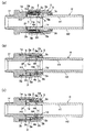
【解決手段】 拡縮スリーブ2の内周面2aとホースHの外周面H2との間に、該拡縮スリーブ2の縮径に伴って径方向へ圧縮変形する環状の弾性体4を設け、この弾性体4の反発力にて上記ホースHの外周面H2がニップル1の外周面1aへ向け押圧されるように上記拡縮スリーブ2を配置することにより、長時間の利用などでホースH自体の弾性力が減少し肉薄になっても、それに伴い弾性体4の反発力でその内周面4aが突出して、ホースHの内周面H1がニップル1の外周面1aに密着され、常にホースHのクランプ状態が保たれる。
【選択図】図1
Description
詳しくは、ニップルの外周面に沿ってホースが挿入され、その外周に拡縮スリーブを介して締め付け具が被せられ、これら拡縮スリーブと締め付け具の軸方向への相互移動により該拡縮スリーブを縮径して、ホースの内周面がニップルの外周面に密着されるホース継手に関する。
また、弾性体の取り付け位置が円筒ナットの内側なので、弾性体を定位置に取り付けることが難しく、弾性体の取り付け作業が面倒であり、しかも該弾性体の取り付け状態が円筒ナットに隠れて目視により有無を確認し難いため、弾性体の取り付けミスが発生し易いという問題もあった。
第二の発明は、第一の発明の目的に加えて、締め付け具の回転操作により拡縮スリーブを捻れることなくスムーズに縮径することを目的としたものである。
第三の発明は、第一の発明又は第二の発明の目的に加えて、ニップルに対するホースの挿入を容易にして確実にシールさせながらホースの抜け強度を高めることを目的としたものである。
第四の発明は、第一の発明、第二の発明又は第三の発明の目的に加えて、弾性体の圧縮変形量を大きく確保することを目的としたものである。
第二の発明は、第一の発明の構成に、前記ニップルに対し、前記締め付け具を軸方向へ移動自在に螺合させ、この締め付け具の内周に押圧スリーブを回転自在に設け、この押圧スリーブの内周を、前記拡縮スリーブの外周面が摺接するテーパー状の加圧内周面とした構成を加えたことを特徴とする。
第三の発明は、第一の発明又は第二の発明の構成に、前記ニップルの外周面に環状の凹部を、前記弾性体と対向して形成した構成を加えたことを特徴とする。
第四の発明は、第一の発明、第二の発明又は第三の発明の構成に、前記弾性体の表面に、該弾性体の圧縮変形に伴いその変形部分が入り込む凹溝部を形成した構成を加えたことを特徴とする。
したがって、弾性体に剪断応力が作用することなく長期間に亘りホースのクランプ状態を保つことができる。
その結果、円筒ナットの回転により弾性体に剪断応力がかかって捻れ易い従来のものに比べ、拡縮スリーブを縮径させるために締め付け具を回転操作しても、その回転が弾性体に直接作用して捻れ変形しないため、確実な回転締め付けができる。
従来は、長時間の利用などでホース自体の弾性力が減少し肉薄になった場合、その対応策として、締め付け具を更に回転して締め付ける、所謂増し締め作業を行っていたが、この増し締め作業が不要となり、メンテナンスの向上が図れる。
また、弾性体の取り付け作業が容易であり、しかも該弾性体の取り付け状態が目視により確認することが容易であるから、弾性体の取り付けミスをも防止できる。
したがって、締め付け具の回転操作により拡縮スリーブを捻れることなくスムーズに縮径することができる。
その結果、締め付け具の回転操作に抵抗感がなく、ホースの接続作業を容易に行える。
したがって、ニップルに対するホースの挿入を容易にして確実にシールさせながらホースの抜け強度を高めることができる。
したがって、弾性体の圧縮変形量を大きく確保することができる。
その結果、ホースの耐クリープ性能の更なる向上が図れる。
さらに、上記ニップル外周面1aの反挿入方向先端に位置する開口端部1dを、反挿入方向へ向けて徐々に大径となるテーパー状に傾斜させ、これと反対のホース挿入方向基端側外周面には、後述する締め付け具3をホース挿入方向及び反挿入方向へ往復動自在に支持するためのスライド手段1eが設けられる。
さらに、上記締め付け具3の外周面には、回転操作用の滑り止め手段3bとして、例えば図示例のように工具などが係合する平面部を周方向へ適宜間隔毎に複数形成したり、ローレットなどの凹凸部を形成することが好ましい。
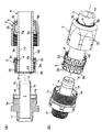
このスリーブ縮径手段としては、相互に対向当接する該締め付け具3の内周面及び拡縮スリーブ2の外周面2dのどちらか一方又は両方を、反挿入方向へ向けて内径が徐々に小径となるテーパー状に傾斜させることも可能であるが、その他の例として、上記締め付け具3の内周に押圧スリーブ5を回転自在に設け、この押圧スリーブ5の内周面を、上記拡縮スリーブ2の外周面2dと対向して、反挿入方向へ向けて内径が徐々に小径となるテーバー状に傾斜する加圧内周面5aとすることが好ましい。
さらに、この弾性体4は、図2(a)に示す如く、その内周面4aを断面略円弧状に湾曲形成し、また該弾性体4の表面には、該弾性体4が圧縮変形した際にその膨出変形した部分が入り込む凹溝部4bを形成することが好ましい。
その具体例としては、その透明又は不透明な外層と内層との間に中間層として、複数本か又は単数本の合成樹脂製ブレード(補強糸)が螺旋状に埋設される積層ホースや、中間層として合成樹脂製又は金属製の断面矩形などの帯状補強材と断面円形などの線状補強材を螺旋状に巻き付けて一体化した螺旋補強ホースや、例えばガラス繊維や難燃性繊維などの糸状補強材をホース外周面に編組した編組補強ホースや、金属製線材や硬質合成樹脂製線材を螺旋状に埋設した螺旋補強ホースや、単層構造の軟質合成樹脂製ホースなどが用いられる。
以下、本発明の一実施例を図面に基づいて説明する。
さらに、図示例では図2(b)に示す如く、前記拡縮スリーブ2のホース挿入方向基端部2eには、上記ニップル1の外周面1aに向けて突出する鍔部2fが形成されている。
その他の例として図示せぬが、凹溝部4bの形成位置を変更したり、凹溝部4bの形状を変更することも可能である。
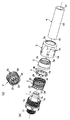
先ず、図2(a)に示すホース継手Aの分解状態から、図3(a)(b)に示す如く、上記ホースHを上記締め付け具3及び上記押圧スリーブ5に挿通し、このホースHの切断面H3に対して、上記拡縮スリーブ2のホース挿入方向基端部2eの鍔部2fを当接させ、ホースHの外周面H2に対し、該拡縮スリーブ2の内周面2aの取付部2cに嵌入された弾性体4の内周面4aを当接させて、押圧スリーブ5を仮止めする。
その際、このニップル1の外周面1aに環状の凹部1cが形成される場合には、ホースHを抵抗なくスムーズに挿入できるという利点がある。
また、この環状の凹部1cによる段差で、ホースHの抜け強度が高くなり、不意なホース抜けを防止できるという利点もある。
この状態で、上記締め付け具3を回転操作して、その内ネジ部3aを上記ニップル1の外ネジ部1eに螺合させる。
その後、長時間の利用などでクリープによりホースH自体の弾性力が減少して肉厚寸法が薄くなった場合には、図1(c)に示す如く、それに伴って上記弾性体4の反発力でその内周面4aが突出する。
その結果、長時間の利用などでクリープによりホースH自体の弾性力が減少して肉厚寸法が薄くなったとしても、締め付け具3を更に回転して締め付ける、所謂増し締め作業が不要となる。
それにより、該ホースHの挟まれた部分H4が押し曲げられて、その内周面H1がニップル1の凹部1cに密着するため、確実にシールさせながらホースの抜け強度を高めることができるという利点がある。
また、このような締め付け具3の軸方向移動による拡縮スリーブ2の縮径に代えて、ホースHを反挿入方向へ引き抜くことにより、それに伴い上記拡縮スリーブ2を締め付け具3の内周面又は押圧スリーブ5の加圧内周面5aに沿い反挿入方向へ移動して縮径されるようにしても良い。
1a 外周面 1b 突き当たり面
1c 凹部 1d 開口端部
1e スライド手段(外ネジ部) 1f 接続部
2 拡縮スリーブ 2a 内周面
2b すり割り 2c 取付部
2d 外周面 2e 基端部
2f 鍔部 3 締め付け具
3a スライド手段(内ネジ部) 3b 滑り止め手段
3c フランジ部 4 弾性体
4a 内周面 4b 凹溝部
5 押圧スリーブ 5a 加圧内周面
5b 係止段部 H ホース
H1 内周面 H2 外周面
H3 切断面 H4 挟まれた部分
Claims (4)
- ニップル(1)の外周面(1a)に沿ってホース(H)が挿入され、その外周に拡縮スリーブ(2)を介して締め付け具(3)が被せられ、これら拡縮スリーブ(2)と締め付け具(3)の軸方向への相互移動により該拡縮スリーブ(2)を縮径して、ホース(H)の内周面(H1)がニップル(1)の外周面(1a)に密着されるホース継手において、
前記拡縮スリーブ(2)の内周面(2a)と前記ホース(H)の外周面(H2)との間に、該拡縮スリーブ(2)の縮径に伴って径方向へ圧縮変形する環状の弾性体(4)を設け、この弾性体(4)の反発力にて上記ホース(H)の外周面(H2)が前記ニップル(1)の外周面(1a)へ向け押圧されるように上記拡縮スリーブ(2)を配置したことを特徴とするホース継手。 - 前記ニップル(1)に対し、前記締め付け具(3)を軸方向へ移動自在に螺合させ、この締め付け具(3)の内周に押圧スリーブ(5)を回転自在に設け、この押圧スリーブ(5)の内周を、前記拡縮スリーブ(2)の外周面(2b)が摺接するテーパー状の加圧内周面(5a)とした請求項1記載のホース継手。
- 前記ニップル(1)の外周面(1a)に環状の凹部(1c)を、前記弾性体(4)と対向して形成した請求項1又は2記載のホース継手。
- 前記弾性体(4)の表面に、該弾性体(4)の圧縮変形に伴いその変形部分が入り込む凹溝部(4b)を形成した請求項1、2又は3記載のホース継手。
Priority Applications (2)
| Application Number | Priority Date | Filing Date | Title |
|---|---|---|---|
| JP2009240840A JP2011069484A (ja) | 2009-09-25 | 2009-09-25 | ホース継手 |
| PCT/JP2010/067012 WO2011037267A1 (ja) | 2009-09-25 | 2010-09-22 | ホース継手 |
Applications Claiming Priority (1)
| Application Number | Priority Date | Filing Date | Title |
|---|---|---|---|
| JP2009240840A JP2011069484A (ja) | 2009-09-25 | 2009-09-25 | ホース継手 |
Publications (2)
| Publication Number | Publication Date |
|---|---|
| JP2011069484A true JP2011069484A (ja) | 2011-04-07 |
| JP2011069484A5 JP2011069484A5 (ja) | 2011-11-10 |
Family
ID=43796006
Family Applications (1)
| Application Number | Title | Priority Date | Filing Date |
|---|---|---|---|
| JP2009240840A Pending JP2011069484A (ja) | 2009-09-25 | 2009-09-25 | ホース継手 |
Country Status (2)
| Country | Link |
|---|---|
| JP (1) | JP2011069484A (ja) |
| WO (1) | WO2011037267A1 (ja) |
Cited By (4)
| Publication number | Priority date | Publication date | Assignee | Title |
|---|---|---|---|---|
| WO2015001993A1 (ja) * | 2013-07-05 | 2015-01-08 | 株式会社 潤工社 | 管継手 |
| WO2015029815A1 (ja) * | 2013-08-30 | 2015-03-05 | 株式会社トヨックス | 管継手 |
| JP2015048887A (ja) * | 2013-08-30 | 2015-03-16 | 株式会社トヨックス | 管継手 |
| JP2015048888A (ja) * | 2013-08-30 | 2015-03-16 | 株式会社トヨックス | 管継手 |
Families Citing this family (1)
| Publication number | Priority date | Publication date | Assignee | Title |
|---|---|---|---|---|
| DE102023129070A1 (de) * | 2023-10-23 | 2025-04-24 | Eisele Gmbh | Verbindungsvorrichtung |
Citations (3)
| Publication number | Priority date | Publication date | Assignee | Title |
|---|---|---|---|---|
| JPH0198995A (ja) * | 1987-10-13 | 1989-04-17 | Hitachi Ltd | 制御棒引抜監視方法、及び同監視装置 |
| JP2002250490A (ja) * | 2001-02-20 | 2002-09-06 | Motonori Ooi | 柔軟樹脂管メカニカル継手 |
| JP2007333176A (ja) * | 2006-06-19 | 2007-12-27 | Nippon Flex Kk | ホース接続用のコネクタ |
Family Cites Families (1)
| Publication number | Priority date | Publication date | Assignee | Title |
|---|---|---|---|---|
| JP2009036239A (ja) * | 2007-07-31 | 2009-02-19 | Nippon Flex Kk | ホース接続用のコネクタ |
-
2009
- 2009-09-25 JP JP2009240840A patent/JP2011069484A/ja active Pending
-
2010
- 2010-09-22 WO PCT/JP2010/067012 patent/WO2011037267A1/ja not_active Ceased
Patent Citations (3)
| Publication number | Priority date | Publication date | Assignee | Title |
|---|---|---|---|---|
| JPH0198995A (ja) * | 1987-10-13 | 1989-04-17 | Hitachi Ltd | 制御棒引抜監視方法、及び同監視装置 |
| JP2002250490A (ja) * | 2001-02-20 | 2002-09-06 | Motonori Ooi | 柔軟樹脂管メカニカル継手 |
| JP2007333176A (ja) * | 2006-06-19 | 2007-12-27 | Nippon Flex Kk | ホース接続用のコネクタ |
Cited By (7)
| Publication number | Priority date | Publication date | Assignee | Title |
|---|---|---|---|---|
| WO2015001993A1 (ja) * | 2013-07-05 | 2015-01-08 | 株式会社 潤工社 | 管継手 |
| JP2015028375A (ja) * | 2013-07-05 | 2015-02-12 | 株式会社潤工社 | 管継手 |
| CN105393037B (zh) * | 2013-07-05 | 2017-05-24 | 株式会社润工社 | 管接头 |
| US10006570B2 (en) | 2013-07-05 | 2018-06-26 | Junkosha Inc. | Pipe joint |
| WO2015029815A1 (ja) * | 2013-08-30 | 2015-03-05 | 株式会社トヨックス | 管継手 |
| JP2015048887A (ja) * | 2013-08-30 | 2015-03-16 | 株式会社トヨックス | 管継手 |
| JP2015048888A (ja) * | 2013-08-30 | 2015-03-16 | 株式会社トヨックス | 管継手 |
Also Published As
| Publication number | Publication date |
|---|---|
| WO2011037267A1 (ja) | 2011-03-31 |
Similar Documents
| Publication | Publication Date | Title |
|---|---|---|
| JP4868371B2 (ja) | ホース継手 | |
| EP2470817B1 (en) | Press-connect fitting with improved grab-ring function | |
| CN101542180B (zh) | 软管连接头 | |
| EP1851475B1 (en) | A coupling | |
| JP5641552B1 (ja) | 管締結構造 | |
| WO2013115044A1 (ja) | 管継手 | |
| WO2011058871A1 (ja) | ホース継手 | |
| JP2011069484A (ja) | ホース継手 | |
| JP2005257065A (ja) | ホース継手 | |
| JP2009144916A (ja) | チューブとチューブ継手との接続方法及びそのチューブ継手 | |
| JP2011102606A (ja) | ホース継手 | |
| JP5137195B2 (ja) | 管継手 | |
| EP2592321B1 (en) | A pipe coupling | |
| JP2018003980A (ja) | 管継手 | |
| JP7401936B1 (ja) | 管継手 | |
| JP5268100B2 (ja) | 管継手 | |
| JP4962849B2 (ja) | 管継手 | |
| JP6421993B2 (ja) | 管継手 | |
| JPH02236087A (ja) | 管をアダプタに回収可能かつ半取外し可能に連結する方法 | |
| JP4403460B2 (ja) | ホース継手 | |
| GB2471502A (en) | A universal compression-type pipe coupling | |
| JP7401937B1 (ja) | 管継手 | |
| JP2018017333A5 (ja) | ||
| JP4469472B2 (ja) | 接続装置 | |
| JP2006308083A (ja) | ホース継手 |
Legal Events
| Date | Code | Title | Description |
|---|---|---|---|
| A711 | Notification of change in applicant |
Free format text: JAPANESE INTERMEDIATE CODE: A711 Effective date: 20110725 |
|
| A521 | Written amendment |
Free format text: JAPANESE INTERMEDIATE CODE: A821 Effective date: 20110725 |
|
| A521 | Written amendment |
Free format text: JAPANESE INTERMEDIATE CODE: A523 Effective date: 20110927 |
|
| A621 | Written request for application examination |
Free format text: JAPANESE INTERMEDIATE CODE: A621 Effective date: 20110927 |
|
| A871 | Explanation of circumstances concerning accelerated examination |
Free format text: JAPANESE INTERMEDIATE CODE: A871 Effective date: 20110927 |
|
| A975 | Report on accelerated examination |
Free format text: JAPANESE INTERMEDIATE CODE: A971005 Effective date: 20111007 |
|
| A131 | Notification of reasons for refusal |
Free format text: JAPANESE INTERMEDIATE CODE: A131 Effective date: 20111018 |
|
| A521 | Written amendment |
Free format text: JAPANESE INTERMEDIATE CODE: A523 Effective date: 20111115 |
|
| A02 | Decision of refusal |
Free format text: JAPANESE INTERMEDIATE CODE: A02 Effective date: 20111206 |