JP2011069484A - Hose joint - Google Patents
Hose joint Download PDFInfo
- Publication number
- JP2011069484A JP2011069484A JP2009240840A JP2009240840A JP2011069484A JP 2011069484 A JP2011069484 A JP 2011069484A JP 2009240840 A JP2009240840 A JP 2009240840A JP 2009240840 A JP2009240840 A JP 2009240840A JP 2011069484 A JP2011069484 A JP 2011069484A
- Authority
- JP
- Japan
- Prior art keywords
- hose
- peripheral surface
- elastic body
- expansion
- outer peripheral
- Prior art date
- Legal status (The legal status is an assumption and is not a legal conclusion. Google has not performed a legal analysis and makes no representation as to the accuracy of the status listed.)
- Pending
Links
- 230000002093 peripheral effect Effects 0.000 claims abstract description 114
- 210000002445 nipple Anatomy 0.000 claims abstract description 54
- 230000008602 contraction Effects 0.000 claims description 58
- 238000003825 pressing Methods 0.000 claims description 21
- 230000008878 coupling Effects 0.000 claims description 5
- 238000010168 coupling process Methods 0.000 claims description 5
- 238000005859 coupling reaction Methods 0.000 claims description 5
- 230000007423 decrease Effects 0.000 abstract description 6
- 230000009467 reduction Effects 0.000 abstract description 4
- 230000002035 prolonged effect Effects 0.000 abstract 1
- 238000010008 shearing Methods 0.000 abstract 1
- 238000003780 insertion Methods 0.000 description 36
- 230000037431 insertion Effects 0.000 description 24
- 239000000463 material Substances 0.000 description 7
- 229920003002 synthetic resin Polymers 0.000 description 7
- 239000000057 synthetic resin Substances 0.000 description 7
- 230000000694 effects Effects 0.000 description 4
- 239000010410 layer Substances 0.000 description 4
- 230000002787 reinforcement Effects 0.000 description 4
- 230000008901 benefit Effects 0.000 description 3
- 239000002184 metal Substances 0.000 description 3
- XLYOFNOQVPJJNP-UHFFFAOYSA-N water Substances O XLYOFNOQVPJJNP-UHFFFAOYSA-N 0.000 description 3
- 230000008859 change Effects 0.000 description 2
- 229920001971 elastomer Polymers 0.000 description 2
- 239000000835 fiber Substances 0.000 description 2
- 239000012530 fluid Substances 0.000 description 2
- 230000007774 longterm Effects 0.000 description 2
- 238000000034 method Methods 0.000 description 2
- 239000012779 reinforcing material Substances 0.000 description 2
- RNFJDJUURJAICM-UHFFFAOYSA-N 2,2,4,4,6,6-hexaphenoxy-1,3,5-triaza-2$l^{5},4$l^{5},6$l^{5}-triphosphacyclohexa-1,3,5-triene Chemical compound N=1P(OC=2C=CC=CC=2)(OC=2C=CC=CC=2)=NP(OC=2C=CC=CC=2)(OC=2C=CC=CC=2)=NP=1(OC=1C=CC=CC=1)OC1=CC=CC=C1 RNFJDJUURJAICM-UHFFFAOYSA-N 0.000 description 1
- 229910001369 Brass Inorganic materials 0.000 description 1
- 229930182556 Polyacetal Natural products 0.000 description 1
- BZHJMEDXRYGGRV-UHFFFAOYSA-N Vinyl chloride Chemical compound ClC=C BZHJMEDXRYGGRV-UHFFFAOYSA-N 0.000 description 1
- 230000015572 biosynthetic process Effects 0.000 description 1
- 239000010951 brass Substances 0.000 description 1
- 230000006835 compression Effects 0.000 description 1
- 238000007906 compression Methods 0.000 description 1
- 238000000354 decomposition reaction Methods 0.000 description 1
- 239000003063 flame retardant Substances 0.000 description 1
- 239000003365 glass fiber Substances 0.000 description 1
- 238000012423 maintenance Methods 0.000 description 1
- 238000012856 packing Methods 0.000 description 1
- 229920006324 polyoxymethylene Polymers 0.000 description 1
- 238000002360 preparation method Methods 0.000 description 1
- 230000008569 process Effects 0.000 description 1
- 230000003014 reinforcing effect Effects 0.000 description 1
- 229920005989 resin Polymers 0.000 description 1
- 239000011347 resin Substances 0.000 description 1
- 238000007789 sealing Methods 0.000 description 1
- -1 silicone rubber Chemical compound 0.000 description 1
- 229920002379 silicone rubber Polymers 0.000 description 1
- 239000004945 silicone rubber Substances 0.000 description 1
- 239000002356 single layer Substances 0.000 description 1
- 239000007779 soft material Substances 0.000 description 1
- 229910001220 stainless steel Inorganic materials 0.000 description 1
- 239000010935 stainless steel Substances 0.000 description 1
- 230000000007 visual effect Effects 0.000 description 1
Images
Classifications
-
- F—MECHANICAL ENGINEERING; LIGHTING; HEATING; WEAPONS; BLASTING
- F16—ENGINEERING ELEMENTS AND UNITS; GENERAL MEASURES FOR PRODUCING AND MAINTAINING EFFECTIVE FUNCTIONING OF MACHINES OR INSTALLATIONS; THERMAL INSULATION IN GENERAL
- F16L—PIPES; JOINTS OR FITTINGS FOR PIPES; SUPPORTS FOR PIPES, CABLES OR PROTECTIVE TUBING; MEANS FOR THERMAL INSULATION IN GENERAL
- F16L33/00—Arrangements for connecting hoses to rigid members; Rigid hose-connectors, i.e. single members engaging both hoses
- F16L33/22—Arrangements for connecting hoses to rigid members; Rigid hose-connectors, i.e. single members engaging both hoses with means not mentioned in the preceding groups for gripping the hose between inner and outer parts
- F16L33/223—Arrangements for connecting hoses to rigid members; Rigid hose-connectors, i.e. single members engaging both hoses with means not mentioned in the preceding groups for gripping the hose between inner and outer parts the sealing surfaces being pressed together by means of a member, e.g. a swivel nut, screwed on or into one of the joint parts
- F16L33/224—Arrangements for connecting hoses to rigid members; Rigid hose-connectors, i.e. single members engaging both hoses with means not mentioned in the preceding groups for gripping the hose between inner and outer parts the sealing surfaces being pressed together by means of a member, e.g. a swivel nut, screwed on or into one of the joint parts a clamping ring being arranged between the threaded member and the connecting member
Landscapes
- Engineering & Computer Science (AREA)
- General Engineering & Computer Science (AREA)
- Mechanical Engineering (AREA)
- Joints That Cut Off Fluids, And Hose Joints (AREA)
Abstract
Description
本発明は、水・油などの液体や空気などの気体や粉体などの流体が通るホースを、配管接続するために用いるホース継手、特に熱湯などの高温な流体でも通すことができる耐熱性に優れたホース継手に関する。
詳しくは、ニップルの外周面に沿ってホースが挿入され、その外周に拡縮スリーブを介して締め付け具が被せられ、これら拡縮スリーブと締め付け具の軸方向への相互移動により該拡縮スリーブを縮径して、ホースの内周面がニップルの外周面に密着されるホース継手に関する。The present invention has a heat resistance that allows passage of a hose through which a fluid such as water or oil, a gas such as air or a fluid such as air passes, such as hot water, especially for hot water. Related to excellent hose fittings.
Specifically, a hose is inserted along the outer peripheral surface of the nipple, and a tightening tool is put on the outer periphery via an expansion / contraction sleeve, and the expansion / contraction sleeve is reduced in diameter by mutual movement of the expansion / contraction sleeve and the tightening tool in the axial direction. And a hose joint in which the inner peripheral surface of the hose is in close contact with the outer peripheral surface of the nipple.
従来、この種のホース継手として、ニップルの基部の外周に形成されたねじによって後退する円筒ナットと、ホースの外周側に位置する拡縮スリーブとの間に、テーパ状の内周面を有する押圧スリーブが設けられ、上記円筒ナットの内周側でその内周先端に形成されるフランジと上記押圧スリーブとの間には、ゴム平パッキンからなる弾性体が設けられ、円筒ナットの回転操作で軸方向後方へ後退させることにより、該円筒ナットのフランジで押された弾性体が押圧スリーブを軸方向後方へ押し、そのテーパ状内周面により拡縮スリーブが縮径されてホースをクランプし、長時間の利用などによりホース自体の弾性力がなくなっても、常にクランプ状態を保つことができるようにしたものがある(例えば、特許文献1参照)。 Conventionally, as this type of hose joint, a pressing sleeve having a tapered inner peripheral surface between a cylindrical nut that is retracted by a screw formed on the outer periphery of the base of the nipple and an expansion / contraction sleeve positioned on the outer peripheral side of the hose An elastic body made of rubber flat packing is provided between the flange formed on the inner peripheral side of the cylindrical nut on the inner peripheral side of the cylindrical nut and the pressing sleeve, and is axially operated by rotating the cylindrical nut. By retracting backward, the elastic body pushed by the flange of the cylindrical nut pushes the pressing sleeve axially rearward, the diameter of the expansion / contraction sleeve is reduced by its tapered inner peripheral surface, and the hose is clamped. There is one in which the clamped state can always be maintained even when the elastic force of the hose itself disappears due to use or the like (see, for example, Patent Document 1).
しかし乍ら、このような従来のホース継手では、円筒ナットのフランジに弾性体が軸方向に支持されているため、円筒ナットを後退させるために回転すると、そのフランジに圧接する弾性体に剪断応力がかかるため、該弾性体が捻れ変形し易く、その反発力により円筒ナットの回転抵抗が大きくなって強い締め付けができなくなるおそれがあるとともに、円筒ナットの回転操作を止めて手を離すと、弾性体の捻れ変形が復元して、円筒ナットによる締め付けが弱くなるという問題があった。
また、弾性体の取り付け位置が円筒ナットの内側なので、弾性体を定位置に取り付けることが難しく、弾性体の取り付け作業が面倒であり、しかも該弾性体の取り付け状態が円筒ナットに隠れて目視により有無を確認し難いため、弾性体の取り付けミスが発生し易いという問題もあった。However, in such a conventional hose joint, since the elastic body is axially supported by the flange of the cylindrical nut, when the cylindrical nut is rotated to retract, the elastic body pressed against the flange is subjected to shear stress. Therefore, the elastic body is easily twisted and deformed, and the rotational resistance of the cylindrical nut may increase due to the repulsive force, and strong tightening may not be possible. There was a problem that the torsional deformation of the body was restored and the tightening by the cylindrical nut was weakened.
In addition, since the elastic body is attached to the inside of the cylindrical nut, it is difficult to attach the elastic body to a fixed position, and the mounting work of the elastic body is troublesome. Since it is difficult to confirm the presence or absence, there is also a problem that an attachment error of the elastic body is likely to occur.
本発明のうち第一の発明は、弾性体に剪断応力が作用することなく長期間に亘りホースのクランプ状態を保つことを目的としたものである。
第二の発明は、第一の発明の目的に加えて、締め付け具の回転操作により拡縮スリーブを捻れることなくスムーズに縮径することを目的としたものである。
第三の発明は、第一の発明又は第二の発明の目的に加えて、ニップルに対するホースの挿入を容易にして確実にシールさせながらホースの抜け強度を高めることを目的としたものである。
第四の発明は、第一の発明、第二の発明又は第三の発明の目的に加えて、弾性体の圧縮変形量を大きく確保することを目的としたものである。The first invention of the present invention is intended to maintain the clamped state of the hose for a long period of time without shear stress acting on the elastic body.
In addition to the object of the first invention, the second invention is intended to smoothly reduce the diameter of the expansion / contraction sleeve without twisting by rotating the fastening tool.
In addition to the objects of the first invention or the second invention, the third invention aims to increase the pull-out strength of the hose while facilitating the insertion of the hose into the nipple and securely sealing.
In addition to the objects of the first invention, the second invention, or the third invention, the fourth invention aims to ensure a large amount of compressive deformation of the elastic body.
前述した目的を達成するために、本発明のうち第一の発明は、拡縮スリーブの内周面とホースの外周面との間に、該拡縮スリーブの縮径に伴って径方向へ圧縮変形する環状の弾性体を設け、この弾性体の反発力にて上記ホースの外周面がニップルの外周面へ向け押圧されるように上記拡縮スリーブを配置したことを特徴とするものである。
第二の発明は、第一の発明の構成に、前記ニップルに対し、前記締め付け具を軸方向へ移動自在に螺合させ、この締め付け具の内周に押圧スリーブを回転自在に設け、この押圧スリーブの内周を、前記拡縮スリーブの外周面が摺接するテーパー状の加圧内周面とした構成を加えたことを特徴とする。
第三の発明は、第一の発明又は第二の発明の構成に、前記ニップルの外周面に環状の凹部を、前記弾性体と対向して形成した構成を加えたことを特徴とする。
第四の発明は、第一の発明、第二の発明又は第三の発明の構成に、前記弾性体の表面に、該弾性体の圧縮変形に伴いその変形部分が入り込む凹溝部を形成した構成を加えたことを特徴とする。In order to achieve the above-described object, the first invention of the present invention is such that the first invention is compressed and deformed in the radial direction between the inner peripheral surface of the expansion / contraction sleeve and the outer peripheral surface of the hose in accordance with the diameter reduction of the expansion / contraction sleeve. An annular elastic body is provided, and the expansion / contraction sleeve is arranged so that the outer peripheral surface of the hose is pressed toward the outer peripheral surface of the nipple by the repulsive force of the elastic body.
According to a second aspect of the invention, in the configuration of the first aspect of the invention, the fastening tool is screwed to the nipple so as to be movable in the axial direction, and a pressing sleeve is rotatably provided on the inner periphery of the fastening tool. A configuration is provided in which the inner periphery of the sleeve is a tapered pressure inner peripheral surface in which the outer peripheral surface of the expansion / contraction sleeve is in sliding contact.
The third invention is characterized in that a configuration in which an annular recess is formed on the outer peripheral surface of the nipple so as to face the elastic body is added to the configuration of the first invention or the second invention.
According to a fourth aspect of the present invention, in the configuration of the first aspect of the invention, the second aspect of the invention, or the third aspect of the invention, a concave groove portion is formed on the surface of the elastic body so that the deformed portion enters along with the compression deformation of the elastic body. It is characterized by adding.
本発明のうち第一の発明は、拡縮スリーブの内周面とホースの外周面との間に、該拡縮スリーブの縮径に伴って径方向へ圧縮変形する環状の弾性体を設け、この弾性体の反発力にて上記ホースがニップルの外周面へ向け押圧されるように上記拡縮スリーブを配置することにより、長時間の利用などでホース自体の弾性力が減少し肉薄になっても、それに伴い弾性体の反発力でその内周面が突出して、ホースの内周面がニップルの外周面に密着され、常にホースのクランプ状態が保たれる。
したがって、弾性体に剪断応力が作用することなく長期間に亘りホースのクランプ状態を保つことができる。
その結果、円筒ナットの回転により弾性体に剪断応力がかかって捻れ易い従来のものに比べ、拡縮スリーブを縮径させるために締め付け具を回転操作しても、その回転が弾性体に直接作用して捻れ変形しないため、確実な回転締め付けができる。
従来は、長時間の利用などでホース自体の弾性力が減少し肉薄になった場合、その対応策として、締め付け具を更に回転して締め付ける、所謂増し締め作業を行っていたが、この増し締め作業が不要となり、メンテナンスの向上が図れる。
また、弾性体の取り付け作業が容易であり、しかも該弾性体の取り付け状態が目視により確認することが容易であるから、弾性体の取り付けミスをも防止できる。According to a first aspect of the present invention, an annular elastic body is provided between the inner peripheral surface of the expansion / contraction sleeve and the outer peripheral surface of the hose so as to be compressed and deformed in the radial direction in accordance with the diameter reduction of the expansion / contraction sleeve. By arranging the expansion and contraction sleeve so that the hose is pressed toward the outer peripheral surface of the nipple by the repulsive force of the body, even if the elastic force of the hose itself decreases and becomes thin due to long-term use, etc. Accordingly, the inner peripheral surface of the elastic body protrudes due to the repulsive force of the elastic body, the inner peripheral surface of the hose is brought into close contact with the outer peripheral surface of the nipple, and the clamp state of the hose is always maintained.
Therefore, the clamped state of the hose can be maintained for a long period without the shear stress acting on the elastic body.
As a result, even if the tightening tool is rotated to reduce the diameter of the expansion / contraction sleeve, the rotation acts directly on the elastic body, compared to the conventional one that is easily twisted due to the shear stress applied to the elastic body by the rotation of the cylindrical nut. Therefore, it can be securely tightened.
Conventionally, when the elastic force of the hose itself decreases and becomes thin due to use for a long time etc., as a countermeasure, so-called retightening work has been performed in which the tightening tool is further rotated and tightened. No work is required and maintenance can be improved.
Moreover, since the attaching operation of the elastic body is easy and the attaching state of the elastic body can be easily confirmed by visual observation, it is possible to prevent an error in attaching the elastic body.
第二の発明は、第一の発明の効果に加えて、ニップルに対し、締め付け具を軸方向へ移動自在に螺合させ、この締め付け具の内周に押圧スリーブを回転自在に設け、この押圧スリーブの内周を、拡縮スリーブの外周面が摺接するテーパー状の加圧内周面とすることにより、締め付け具の回転操作と関係なく、押圧スリーブが無回転で維持されるとともに、弾性体の反発力で拡縮スリーブが軸方向逆向きに押動され、その外周面が押圧スリーブのテーパー状の加圧内周面に沿って摺接して縮径される。
したがって、締め付け具の回転操作により拡縮スリーブを捻れることなくスムーズに縮径することができる。
その結果、締め付け具の回転操作に抵抗感がなく、ホースの接続作業を容易に行える。In the second invention, in addition to the effects of the first invention, a fastening tool is screwed to the nipple so as to be movable in the axial direction, and a pressing sleeve is rotatably provided on the inner periphery of the fastening tool. By making the inner periphery of the sleeve a tapered pressure inner peripheral surface in which the outer peripheral surface of the expansion / contraction sleeve is in sliding contact, the pressing sleeve can be maintained without rotation regardless of the rotation operation of the tightening tool, and the elastic body The expansion / contraction sleeve is pushed in the opposite axial direction by the repulsive force, and the outer peripheral surface thereof is slidably contacted along the tapered pressure inner peripheral surface of the pressing sleeve to reduce the diameter.
Therefore, the diameter of the expansion / contraction sleeve can be smoothly reduced without being twisted by rotating the tightening tool.
As a result, there is no resistance to the rotating operation of the fastening tool, and the hose connection work can be easily performed.
第三の発明は、第一の発明又は第二の発明の効果に加えて、ニップルの外周面に環状の凹部を、弾性体と対向して形成することにより、ニップルの外周面にホースが抵抗なくスムーズに挿入可能となるとともに、弾性体の反発力にてホースがニップルの外周面へ向け押し曲げられて、その内周面がニップルの凹部に密着する。
したがって、ニップルに対するホースの挿入を容易にして確実にシールさせながらホースの抜け強度を高めることができる。In the third invention, in addition to the effects of the first invention or the second invention, an annular recess is formed on the outer peripheral surface of the nipple so as to face the elastic body, so that the hose resists the outer peripheral surface of the nipple. The hose is pushed and bent toward the outer peripheral surface of the nipple by the repulsive force of the elastic body, and the inner peripheral surface is in close contact with the concave portion of the nipple.
Therefore, the hose pull-out strength can be increased while the hose can be easily inserted into the nipple and reliably sealed.
第四の発明は、第一の発明、第二の発明又は第三の発明の効果に加えて、弾性体の表面に凹溝部を形成することにより、該弾性体が圧縮変形した際にその変形部分が上記凹溝部に入り込む。
したがって、弾性体の圧縮変形量を大きく確保することができる。
その結果、ホースの耐クリープ性能の更なる向上が図れる。In addition to the effects of the first invention, the second invention, or the third invention, the fourth invention is formed by forming a concave groove on the surface of the elastic body so that the elastic body is deformed when it is compressively deformed. The portion enters the concave groove.
Therefore, a large amount of compressive deformation of the elastic body can be ensured.
As a result, the creep resistance of the hose can be further improved.
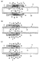
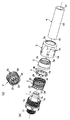
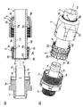
本発明のホース継手Aの実施形態は、図1〜図3に示す如く、可撓性ホースHの接続端部が挿入されるニップル1と、このニップル1の外周面1aにホースHの接続端部を介して配置される拡縮スリーブ2と、この拡縮スリーブ2を軸方向へ往復動自在に案内する締め付け具3とを備え、上記ニップル1の外周面1aにホースHの接続端部が挿入された後に、上記締め付け具3を軸方向、例えばホースHの挿入方向(以下ホース挿入方向という)に移動させて、該拡縮スリーブ2を縮径するか、又はホースHのホース挿入方向と逆方向(以下反挿入方向という)への引き抜き動作に伴い上記拡縮スリーブ2を反挿入方向へ移動させて、該拡縮スリーブ2を縮径することにより、このホースHの接続端部の内周面H1がニップル1の外周面1aに密着されて該ホースHを引き抜き不能に接続するものである。 As shown in FIGS. 1 to 3, the embodiment of the hose joint A of the present invention includes a
そして、上記拡縮スリーブ2の内周面2aと、上記ホースHの外周面H2との間には、これら両者間に亘ってスリーブ2の内周面2aに弾性体4が軸方向へ移動不能に設けられ、上記拡縮スリーブ2の縮径に伴い該弾性体4を径方向へ圧縮変形させることにより、この弾性体4の反発力にて上記ホースHの外周面H2を上記ニップル1の外周面1aへ向け更に押圧して変形させ、それにより該ホースHの内周面H1がニップル1の外周面1aに密着するようにしている。 And between the inner
上記ニップル1は、例えば真鍮などの金属や硬質合成樹脂などの硬質材料で、ホースHの内径と略同じか又はそれよりも若干大きい外径を有する円筒状に形成するか、或いは例えばステンレスなどの変形可能な剛性材料からなる板材をプレス加工やその他の成形加工することで肉厚が薄い円筒状に形成され、そのホース挿入方向基端側には、後述する拡縮スリーブ2のホース挿入方向基端と対向する環状の突き当たり面1bが形成される。 The
上記ニップル1の外周面1aには、後述する弾性体4と対向する環状の凹部1cを形成することが好ましい。
さらに、上記ニップル外周面1aの反挿入方向先端に位置する開口端部1dを、反挿入方向へ向けて徐々に大径となるテーパー状に傾斜させ、これと反対のホース挿入方向基端側外周面には、後述する締め付け具3をホース挿入方向及び反挿入方向へ往復動自在に支持するためのスライド手段1eが設けられる。In the outer
Further, the
上記拡縮スリーブ2は、例えばポリアセタール樹脂やそれ以外の表面の滑り性と耐熱性に優れた合成樹脂などの弾性変形可能な材料で、その内径が上記ホースHの外径より若干大きい略円筒状に形成され、その内周面2aを上記ニップル1の外周面1aと略平行にするとともに、図2(a)(b)に示す如く、ホース挿入方向及び反挿入方向のどちらか一方又は両方向へ延びるすり割り2bを周方向へ複数切欠形成することにより、径方向へスムーズに弾性変形するようにしている。 The expansion /
上記拡縮スリーブ2の内周面2aの反挿入方向先端側には、後述する弾性体4を位置決めするための取付部2cが、上記ニップル1の外周面1aの環状凹部1cと対向して環状に凹設され、必要に応じて該取付部2cをホース挿入方向へ複数配置することも可能である。 A
上記締め付け具3は、上記ニップル1と同種の材料でホースHの外径よりも大きい内径を有する略円筒状に形成され、その内周面には、上記ニップル1のホース挿入方向基端側外周面と係合してホース挿入方向及び反挿入方向へ往復動自在に支持するためのスライド手段3aが設けられる。
さらに、上記締め付け具3の外周面には、回転操作用の滑り止め手段3bとして、例えば図示例のように工具などが係合する平面部を周方向へ適宜間隔毎に複数形成したり、ローレットなどの凹凸部を形成することが好ましい。The
Further, on the outer peripheral surface of the
また、上記締め付け具3と上記拡縮スリーブ2との対向面、即ち締め付け具3の内周面から拡縮スリーブ2の外周面2dに亘って拡縮スリーブ2を径方向へ加圧し縮径させる手段が設けられる。
このスリーブ縮径手段としては、相互に対向当接する該締め付け具3の内周面及び拡縮スリーブ2の外周面2dのどちらか一方又は両方を、反挿入方向へ向けて内径が徐々に小径となるテーパー状に傾斜させることも可能であるが、その他の例として、上記締め付け具3の内周に押圧スリーブ5を回転自在に設け、この押圧スリーブ5の内周面を、上記拡縮スリーブ2の外周面2dと対向して、反挿入方向へ向けて内径が徐々に小径となるテーバー状に傾斜する加圧内周面5aとすることが好ましい。Further, there is provided means for pressurizing and reducing the diameter of the expansion /
As this sleeve diameter reducing means, either one or both of the inner peripheral surface of the
上記弾性体4は、例えばゴムなどの圧縮変形可能な材料で円環状に形成され、その外周部分を、上記拡縮スリーブ2の内周面2aに形成される取付部2cに対し、嵌合させるなどして移動不能に配置することで、該弾性体4の内周面4aが上記ホースHの外周面H2へ向け突出するように位置決めしている。
さらに、この弾性体4は、図2(a)に示す如く、その内周面4aを断面略円弧状に湾曲形成し、また該弾性体4の表面には、該弾性体4が圧縮変形した際にその膨出変形した部分が入り込む凹溝部4bを形成することが好ましい。The
Further, as shown in FIG. 2 (a), the
一方、上記ホースHは、例えば塩化ビニルなどの軟質合成樹脂やシリコーンゴムなどの軟質材料で構成され、その内周面H1と外周面H2が平坦なものが好ましい。
その具体例としては、その透明又は不透明な外層と内層との間に中間層として、複数本か又は単数本の合成樹脂製ブレード(補強糸)が螺旋状に埋設される積層ホースや、中間層として合成樹脂製又は金属製の断面矩形などの帯状補強材と断面円形などの線状補強材を螺旋状に巻き付けて一体化した螺旋補強ホースや、例えばガラス繊維や難燃性繊維などの糸状補強材をホース外周面に編組した編組補強ホースや、金属製線材や硬質合成樹脂製線材を螺旋状に埋設した螺旋補強ホースや、単層構造の軟質合成樹脂製ホースなどが用いられる。
以下、本発明の一実施例を図面に基づいて説明する。On the other hand, the hose H is preferably made of a soft synthetic resin such as vinyl chloride or a soft material such as silicone rubber, and the inner peripheral surface H1 and the outer peripheral surface H2 thereof are flat.
Specific examples thereof include a laminated hose in which a plurality or a single synthetic resin blade (reinforcing yarn) is spirally embedded as an intermediate layer between the transparent or opaque outer layer and inner layer, and an intermediate layer As a spiral reinforcement hose in which a strip-shaped reinforcing material made of synthetic resin or metal, such as a rectangular cross section, and a linear reinforcing material, such as a circular cross section, are spirally wound and integrated, for example, fiber reinforcement such as glass fiber or flame-retardant fiber A braided reinforcement hose in which a material is braided on the outer peripheral surface of the hose, a spiral reinforcement hose in which a metal wire or a hard synthetic resin wire is embedded spirally, a soft synthetic resin hose having a single layer structure, or the like is used.
Hereinafter, an embodiment of the present invention will be described with reference to the drawings.
この実施例1は、図1(a)〜(c),図2(a)(b)及び図3(a)(b)に示す如く、前記ニップル1の外周面のスライド手段1eとして外ネジ部を刻設し、これと対向する前記締め付け具3の内周面のスライド手段3aとして内ネジ部を刻設し、これら外ネジ部1e及び内ネジ部3aを螺合して、上記締め付け具3の回転操作により上記ニップル1に対し該締め付け具3及び前記押圧スリーブ5が軸方向へ往復動自在に取り付けられるとともに、上記ニップル1の外ネジ部1eよりもホース挿入方向基端側には、他の機器の管接続口(図示せず)に接続するための接続部1fが連設される場合を示すものである。 As shown in FIGS. 1A to 1C, FIGS. 2A and 2B, and FIGS. 3A and 3B, the first embodiment uses an external screw as a sliding
図示例では、上記外ネジ部1eが刻設されるニップル1の基端側外周部と、前記ニップル外周面1aとの間を凹状に形成して、その底面部分を前記ニップル1の突き当たり面1bとしている。
さらに、図示例では図2(b)に示す如く、前記拡縮スリーブ2のホース挿入方向基端部2eには、上記ニップル1の外周面1aに向けて突出する鍔部2fが形成されている。In the illustrated example, a concave portion is formed between the base end side outer peripheral portion of the
Furthermore, in the illustrated example, as shown in FIG. 2B, a
そして、上記締め付け具3の反挿入方向先端には、前記ホースHの外周面H2へ向けて突出するフランジ部3cが形成され、該締め付け具3の内周に配置される前記押圧スリーブ5の外周面には係止段部5bを形成し、これらフランジ部3cと係止段部5bを回転自在に摺接させることにより、上記締め付け具3のホース挿入方向への回転移動に伴って、該押圧スリーブ5が同方向へ連動するようにしている。 And the
前記弾性体4の内周面4a及び外周面には、図2(a)に示す如く、前記凹溝部4bを周方向へ適宜間隔ごとに複数凹設して、該弾性体4全体を径方向へスムーズに弾性変形させている。
その他の例として図示せぬが、凹溝部4bの形成位置を変更したり、凹溝部4bの形状を変更することも可能である。As shown in FIG. 2A, a plurality of concave grooves 4b are provided in the circumferential direction at appropriate intervals on the inner
Although not shown as another example, it is possible to change the formation position of the groove 4b or change the shape of the groove 4b.
また、上記接続部1fは、斯かるホース継手Aに接続する他の機器の管接続口の内周面に内ネジが刻設される場合には、これと対応する外ネジを刻設し、また該管接続口の外周面に外ネジが刻設される場合には、これと対応する内ネジを刻設している。 In addition, when the internal thread is engraved on the inner peripheral surface of the pipe connection port of another device connected to the hose joint A, the
図示例の場合には上記ニップル1が、円筒材料を例えば切削加工などで削り出した切削品であり、そのホース挿入方向基端には、前記接続部1fとして外ネジが刻設されている。 In the case of the illustrated example, the
次に、斯かるホース継手AによるホースHの接続方法を工程順に従って説明し、それにより得られる作用効果についても説明する。
先ず、図2(a)に示すホース継手Aの分解状態から、図3(a)(b)に示す如く、上記ホースHを上記締め付け具3及び上記押圧スリーブ5に挿通し、このホースHの切断面H3に対して、上記拡縮スリーブ2のホース挿入方向基端部2eの鍔部2fを当接させ、ホースHの外周面H2に対し、該拡縮スリーブ2の内周面2aの取付部2cに嵌入された弾性体4の内周面4aを当接させて、押圧スリーブ5を仮止めする。Next, the connection method of the hose H by such a hose coupling A will be described according to the order of steps, and the effects obtained thereby will also be described.
First, from the disassembled state of the hose joint A shown in FIG. 2A, as shown in FIGS. 3A and 3B, the hose H is inserted into the
その後、図1(a)に示す如く、上記ニップル1の外周面1aにホースHの接続端部を挿入する。
その際、このニップル1の外周面1aに環状の凹部1cが形成される場合には、ホースHを抵抗なくスムーズに挿入できるという利点がある。
また、この環状の凹部1cによる段差で、ホースHの抜け強度が高くなり、不意なホース抜けを防止できるという利点もある。Thereafter, as shown in FIG. 1A, the connecting end of the hose H is inserted into the outer
In that case, when the annular recessed
Further, the step formed by the
このようなホースHの挿入に伴って、該ホースHの切断面H3が、上記拡縮スリーブ2のホース挿入方向基端部2eの鍔部2fを挟んで上記突き当たり面1bに突き当たり、これでホースHの挿入作業が終了する。
この状態で、上記締め付け具3を回転操作して、その内ネジ部3aを上記ニップル1の外ネジ部1eに螺合させる。As the hose H is inserted, the cut surface H3 of the hose H abuts against the abutting
In this state, the
これに続いて、図1(b)に示す如く、上記締め付け具3をねじ込んで上記ニップル1に対しホース挿入方向へ後退移動させると、該締め付け具3のフランジ部3cを介して上記押圧スリーブ5が同方向へ後退移動し、そのテーパー状加圧内周面5aが上記拡縮スリーブ2の先端外周面2dと接触して、該拡縮スリーブ2をホース挿入方向へ押圧する。 Subsequently, as shown in FIG. 1B, when the
それにより、この拡縮スリーブ2の先端外周面2dが上記押圧スリーブ5のテーパー状加圧内周面5aに沿って後退移動することで径方向へ加圧されて圧縮変形し、それに伴い該拡縮スリーブ2の先端内周に位置決めされた弾性体4の内周面4aがホースHの外周面H2に圧接し、そのホース内周面H1を上記ニップル1の外周面1aの環状凹部1cに密着させてクランプすると同時に、該弾性体4が径方向へ圧縮変形する。 As a result, the distal outer
この際、上記締め付け具3のフランジ部3cと上記押圧スリーブ5の係止段部5bとが回転自在に摺接するため、これら押圧スリーブ5のテーパー状加圧内周面5aと拡縮スリーブ2の外周面との接触抵抗で該押圧スリーブ5は無回転となり、拡縮スリーブ2に剪断応力は発生せず、該拡縮スリーブ2が捻れ変形することを防止しながらスムーズに縮径できるという利点がある。 At this time, since the
そして、上記締め付け具3のねじ込みが終わった時点で、ホースHの接続作業が完了する。
その後、長時間の利用などでクリープによりホースH自体の弾性力が減少して肉厚寸法が薄くなった場合には、図1(c)に示す如く、それに伴って上記弾性体4の反発力でその内周面4aが突出する。Then, when the screwing of the
Thereafter, when the elastic force of the hose H itself decreases due to creep due to creep or the like and the wall thickness becomes thin, the repulsive force of the
それにより、該弾性体4の内周面4aがホースHの外周面H2に圧接し、該ホース内周面H1を上記ニップル1の外周面1aの環状凹部1cに密着させてクランプするため、常にホースHのクランプ状態が保たれる。
その結果、長時間の利用などでクリープによりホースH自体の弾性力が減少して肉厚寸法が薄くなったとしても、締め付け具3を更に回転して締め付ける、所謂増し締め作業が不要となる。Accordingly, the inner
As a result, even if the elastic force of the hose H itself decreases due to creep due to long-term use or the like and the wall thickness becomes thin, so-called additional tightening work for further rotating and tightening the
また、このようなホースHのクランプ状態では、上記弾性体4の反発力により、その内周面4aがホースHを挟んでニップル1の凹部1cへ向け圧接する。
それにより、該ホースHの挟まれた部分H4が押し曲げられて、その内周面H1がニップル1の凹部1cに密着するため、確実にシールさせながらホースの抜け強度を高めることができるという利点がある。Further, in such a clamped state of the hose H, the inner
Thereby, the portion H4 between which the hose H is sandwiched is pushed and bent, and the inner peripheral surface H1 thereof is brought into close contact with the
なお、前示実施例では、前記ニップル1に対し前記締め付け具3を軸方向移動させるスライド手段1e,3aとして互いに螺合する外ネジ部と内ネジ部を形成したが、これに限定されず、少なくとも拡縮スリーブ2に対して締め付け具3を軸方向移動させることができれば、ネジ以外の構造であっても良い。
また、このような締め付け具3の軸方向移動による拡縮スリーブ2の縮径に代えて、ホースHを反挿入方向へ引き抜くことにより、それに伴い上記拡縮スリーブ2を締め付け具3の内周面又は押圧スリーブ5の加圧内周面5aに沿い反挿入方向へ移動して縮径されるようにしても良い。In the previous embodiment, the outer screw portion and the inner screw portion that are screwed together are formed as the slide means 1e and 3a for moving the
Further, instead of reducing the diameter of the expansion /
さらに、前記拡縮スリーブ2のホース挿入方向基端部2eに突出形成される鍔部2fを、前記ニップル1の突き当たり面1bと前記ホースHの切断面H3との間に挟み込むように配置したが、これに限定されず、図示せぬが該鍔部2fを形成せずに、上記ホースHの切断面H3をニップル1の突き当たり面1bに直接当接させて、その外側と前記締め付け具3との間に上記拡縮スリーブ2を移動不能に配置するようにしても良い。 Further, the
A ホース継手 1 ニップル
1a 外周面 1b 突き当たり面
1c 凹部 1d 開口端部
1e スライド手段(外ネジ部) 1f 接続部
2 拡縮スリーブ 2a 内周面
2b すり割り 2c 取付部
2d 外周面 2e 基端部
2f 鍔部 3 締め付け具
3a スライド手段(内ネジ部) 3b 滑り止め手段
3c フランジ部 4 弾性体
4a 内周面 4b 凹溝部
5 押圧スリーブ 5a 加圧内周面
5b 係止段部 H ホース
H1 内周面 H2 外周面
H3 切断面 H4 挟まれた部分A
Claims (4)
前記拡縮スリーブ(2)の内周面(2a)と前記ホース(H)の外周面(H2)との間に、該拡縮スリーブ(2)の縮径に伴って径方向へ圧縮変形する環状の弾性体(4)を設け、この弾性体(4)の反発力にて上記ホース(H)の外周面(H2)が前記ニップル(1)の外周面(1a)へ向け押圧されるように上記拡縮スリーブ(2)を配置したことを特徴とするホース継手。A hose (H) is inserted along the outer peripheral surface (1a) of the nipple (1), and a clamp (3) is put on the outer periphery via an expansion / contraction sleeve (2). The expansion / contraction sleeve (2) and the clamp The expansion / contraction sleeve (2) is reduced in diameter by mutual movement of (3) in the axial direction, and the inner peripheral surface (H1) of the hose (H) is in close contact with the outer peripheral surface (1a) of the nipple (1). In the joint,
Between the inner peripheral surface (2a) of the expansion / contraction sleeve (2) and the outer peripheral surface (H2) of the hose (H), a ring-shaped member that compresses and deforms in the radial direction along with the contraction of the expansion / contraction sleeve (2). An elastic body (4) is provided, and the outer surface (H2) of the hose (H) is pressed toward the outer surface (1a) of the nipple (1) by the repulsive force of the elastic body (4). A hose coupling characterized by arranging an expansion / contraction sleeve (2).
Priority Applications (2)
| Application Number | Priority Date | Filing Date | Title |
|---|---|---|---|
| JP2009240840A JP2011069484A (en) | 2009-09-25 | 2009-09-25 | Hose joint |
| PCT/JP2010/067012 WO2011037267A1 (en) | 2009-09-25 | 2010-09-22 | Hose joint |
Applications Claiming Priority (1)
| Application Number | Priority Date | Filing Date | Title |
|---|---|---|---|
| JP2009240840A JP2011069484A (en) | 2009-09-25 | 2009-09-25 | Hose joint |
Publications (2)
| Publication Number | Publication Date |
|---|---|
| JP2011069484A true JP2011069484A (en) | 2011-04-07 |
| JP2011069484A5 JP2011069484A5 (en) | 2011-11-10 |
Family
ID=43796006
Family Applications (1)
| Application Number | Title | Priority Date | Filing Date |
|---|---|---|---|
| JP2009240840A Pending JP2011069484A (en) | 2009-09-25 | 2009-09-25 | Hose joint |
Country Status (2)
| Country | Link |
|---|---|
| JP (1) | JP2011069484A (en) |
| WO (1) | WO2011037267A1 (en) |
Cited By (4)
| Publication number | Priority date | Publication date | Assignee | Title |
|---|---|---|---|---|
| WO2015001993A1 (en) * | 2013-07-05 | 2015-01-08 | 株式会社 潤工社 | Pipe joint |
| WO2015029815A1 (en) * | 2013-08-30 | 2015-03-05 | 株式会社トヨックス | Tube joint |
| JP2015048888A (en) * | 2013-08-30 | 2015-03-16 | 株式会社トヨックス | Pipe joint |
| JP2015048887A (en) * | 2013-08-30 | 2015-03-16 | 株式会社トヨックス | Pipe joint |
Families Citing this family (1)
| Publication number | Priority date | Publication date | Assignee | Title |
|---|---|---|---|---|
| DE102023129070A1 (en) * | 2023-10-23 | 2025-04-24 | Eisele Gmbh | connecting device |
Citations (3)
| Publication number | Priority date | Publication date | Assignee | Title |
|---|---|---|---|---|
| JPH0198995A (en) * | 1987-10-13 | 1989-04-17 | Hitachi Ltd | Method and device for monitoring drawing-out of control rod |
| JP2002250490A (en) * | 2001-02-20 | 2002-09-06 | Motonori Ooi | Mechanical joint for flexible resin pipe |
| JP2007333176A (en) * | 2006-06-19 | 2007-12-27 | Nippon Flex Kk | Connector for connecting hose |
Family Cites Families (1)
| Publication number | Priority date | Publication date | Assignee | Title |
|---|---|---|---|---|
| JP2009036239A (en) * | 2007-07-31 | 2009-02-19 | Nippon Flex Kk | Connector for connecting hose |
-
2009
- 2009-09-25 JP JP2009240840A patent/JP2011069484A/en active Pending
-
2010
- 2010-09-22 WO PCT/JP2010/067012 patent/WO2011037267A1/en not_active Ceased
Patent Citations (3)
| Publication number | Priority date | Publication date | Assignee | Title |
|---|---|---|---|---|
| JPH0198995A (en) * | 1987-10-13 | 1989-04-17 | Hitachi Ltd | Method and device for monitoring drawing-out of control rod |
| JP2002250490A (en) * | 2001-02-20 | 2002-09-06 | Motonori Ooi | Mechanical joint for flexible resin pipe |
| JP2007333176A (en) * | 2006-06-19 | 2007-12-27 | Nippon Flex Kk | Connector for connecting hose |
Cited By (7)
| Publication number | Priority date | Publication date | Assignee | Title |
|---|---|---|---|---|
| WO2015001993A1 (en) * | 2013-07-05 | 2015-01-08 | 株式会社 潤工社 | Pipe joint |
| JP2015028375A (en) * | 2013-07-05 | 2015-02-12 | 株式会社潤工社 | Pipe joint |
| CN105393037B (en) * | 2013-07-05 | 2017-05-24 | 株式会社润工社 | Fitting |
| US10006570B2 (en) | 2013-07-05 | 2018-06-26 | Junkosha Inc. | Pipe joint |
| WO2015029815A1 (en) * | 2013-08-30 | 2015-03-05 | 株式会社トヨックス | Tube joint |
| JP2015048888A (en) * | 2013-08-30 | 2015-03-16 | 株式会社トヨックス | Pipe joint |
| JP2015048887A (en) * | 2013-08-30 | 2015-03-16 | 株式会社トヨックス | Pipe joint |
Also Published As
| Publication number | Publication date |
|---|---|
| WO2011037267A1 (en) | 2011-03-31 |
Similar Documents
| Publication | Publication Date | Title |
|---|---|---|
| JP4868371B2 (en) | Hose fittings | |
| EP2470817B1 (en) | Press-connect fitting with improved grab-ring function | |
| CN101542180B (en) | Hose joint | |
| EP1851475B1 (en) | A coupling | |
| JP5641552B1 (en) | Pipe fastening structure | |
| WO2013115044A1 (en) | Pipe joint | |
| WO2011058871A1 (en) | Hose connector | |
| JP2011069484A (en) | Hose joint | |
| JP2005257065A (en) | Hose fittings | |
| JP2009144916A (en) | Connection method of tube and tube joint, and tube joint | |
| JP2011102606A (en) | Hose connector | |
| JP2009270622A (en) | Pipe joint | |
| EP2592321B1 (en) | A pipe coupling | |
| JP2018003980A (en) | Pipe joint | |
| JP5268100B2 (en) | Pipe fitting | |
| JP4962849B2 (en) | Pipe fitting | |
| JP6421993B2 (en) | Pipe fitting | |
| JPH02236087A (en) | Method for recoverably and removably coupling pipe to adapter | |
| JP4403460B2 (en) | Hose fittings | |
| GB2471502A (en) | A universal compression-type pipe coupling | |
| JP7401937B1 (en) | pipe fittings | |
| JP2018017333A5 (en) | ||
| JP7401936B1 (en) | pipe fittings | |
| JP4469472B2 (en) | Connected device | |
| JP2006308083A (en) | Hose joint |
Legal Events
| Date | Code | Title | Description |
|---|---|---|---|
| A711 | Notification of change in applicant |
Free format text: JAPANESE INTERMEDIATE CODE: A711 Effective date: 20110725 |
|
| A521 | Written amendment |
Free format text: JAPANESE INTERMEDIATE CODE: A821 Effective date: 20110725 |
|
| A521 | Written amendment |
Free format text: JAPANESE INTERMEDIATE CODE: A523 Effective date: 20110927 |
|
| A621 | Written request for application examination |
Free format text: JAPANESE INTERMEDIATE CODE: A621 Effective date: 20110927 |
|
| A871 | Explanation of circumstances concerning accelerated examination |
Free format text: JAPANESE INTERMEDIATE CODE: A871 Effective date: 20110927 |
|
| A975 | Report on accelerated examination |
Free format text: JAPANESE INTERMEDIATE CODE: A971005 Effective date: 20111007 |
|
| A131 | Notification of reasons for refusal |
Free format text: JAPANESE INTERMEDIATE CODE: A131 Effective date: 20111018 |
|
| A521 | Written amendment |
Free format text: JAPANESE INTERMEDIATE CODE: A523 Effective date: 20111115 |
|
| A02 | Decision of refusal |
Free format text: JAPANESE INTERMEDIATE CODE: A02 Effective date: 20111206 |