JP4868371B2 - Hose fittings - Google Patents
Hose fittings Download PDFInfo
- Publication number
- JP4868371B2 JP4868371B2 JP2009202862A JP2009202862A JP4868371B2 JP 4868371 B2 JP4868371 B2 JP 4868371B2 JP 2009202862 A JP2009202862 A JP 2009202862A JP 2009202862 A JP2009202862 A JP 2009202862A JP 4868371 B2 JP4868371 B2 JP 4868371B2
- Authority
- JP
- Japan
- Prior art keywords
- hose
- peripheral surface
- diameter
- outer peripheral
- expansion
- Prior art date
- Legal status (The legal status is an assumption and is not a legal conclusion. Google has not performed a legal analysis and makes no representation as to the accuracy of the status listed.)
- Active
Links
Images


Classifications
-
- F—MECHANICAL ENGINEERING; LIGHTING; HEATING; WEAPONS; BLASTING
- F16—ENGINEERING ELEMENTS AND UNITS; GENERAL MEASURES FOR PRODUCING AND MAINTAINING EFFECTIVE FUNCTIONING OF MACHINES OR INSTALLATIONS; THERMAL INSULATION IN GENERAL
- F16L—PIPES; JOINTS OR FITTINGS FOR PIPES; SUPPORTS FOR PIPES, CABLES OR PROTECTIVE TUBING; MEANS FOR THERMAL INSULATION IN GENERAL
- F16L33/00—Arrangements for connecting hoses to rigid members; Rigid hose connectors, i.e. single members engaging both hoses
- F16L33/22—Arrangements for connecting hoses to rigid members; Rigid hose connectors, i.e. single members engaging both hoses with means not mentioned in the preceding groups for gripping the hose between inner and outer parts
- F16L33/223—Arrangements for connecting hoses to rigid members; Rigid hose connectors, i.e. single members engaging both hoses with means not mentioned in the preceding groups for gripping the hose between inner and outer parts the sealing surfaces being pressed together by means of a member, e.g. a swivel nut, screwed on or into one of the joint parts
- F16L33/224—Arrangements for connecting hoses to rigid members; Rigid hose connectors, i.e. single members engaging both hoses with means not mentioned in the preceding groups for gripping the hose between inner and outer parts the sealing surfaces being pressed together by means of a member, e.g. a swivel nut, screwed on or into one of the joint parts a clamping ring being arranged between the threaded member and the connecting member
Description
本発明は、例えばシリコーンゴムなどのような柔らかくて変形し易いホースを配管接続するために用いるホース継手に関する。
詳しくは、ニップルの外周面に沿ってホースが挿入され、その外側に設けられた締め付け具の軸方向移動により、ホースの内周面がニップルの外周面に密着されるホース継手に関する。
The present invention relates to a hose joint used for pipe connection of a soft and easily deformable hose such as silicone rubber.
More specifically, the present invention relates to a hose joint in which a hose is inserted along the outer peripheral surface of the nipple and the inner peripheral surface of the hose is in close contact with the outer peripheral surface of the nipple by the axial movement of a fastening tool provided outside the nipple.
従来、この種のホース継手には、ニップルとして構成される第2ジョイントと接続するナットと、該ナットの雌ねじ後方内周面に配置されてホース先端の外周面との間に介装されるフロントリングと、該フロントリングから所定間隔離間してナットの後端内周面とホースの外周面との間に介装されるバックリングと、第2ジョイントと接続した状態においてホース端部側の内周面に嵌入され、該ホース端部側の内外周面をフロントリング乃至バックリングと共に挟持するインサートスリーブとから構成されるものがある(例えば、特許文献1参照)。
その接続時には、先ずナットにバックリングを係合させた状態で、このバックリングをナットと共にホースの外周に挿入して後方に設定し、次にインサートスリーブをホースの端末に嵌入した後、このインサートスリーブを第2ジョイントに嵌合するとともに、ホース端末の外周に嵌合したフロントリングを第2ジョイントに嵌合させる。そして、ナットを第2ジョイントに対し螺合することで、バックリングがフロントリング側に引き寄せられて、インサートスリーブの環状凸部ないし、その両湾曲斜面に外嵌されているホースの外周がフロントリングないしバックリングで径方向にしっかりと挟持されると同時に、環状凸部によって径方向に膨出変形した部位がフロントリングないしバックリングにより軸方向に挟持されている。
Conventionally, this type of hose joint includes a nut connected to a second joint configured as a nipple, and a front disposed between the inner peripheral surface of the rear end of the female screw and the front end of the hose. A ring, a back ring interposed between the rear end inner peripheral surface of the nut and the outer peripheral surface of the hose at a predetermined distance from the front ring, and an inner portion on the hose end side in a state of being connected to the second joint. There is an insert sleeve that is inserted into the peripheral surface and sandwiches the inner and outer peripheral surfaces on the hose end side together with a front ring or a back ring (see, for example, Patent Document 1).
At the time of connection, first, with the buckling engaged with the nut, insert the buckling into the outer periphery of the hose together with the nut and then set it back, and then insert the insert sleeve into the end of the hose. The sleeve is fitted to the second joint, and the front ring fitted to the outer periphery of the hose end is fitted to the second joint. Then, by screwing the nut to the second joint, the back ring is drawn to the front ring side, and the outer periphery of the hose that is fitted on the annular convex portion of the insert sleeve or both curved slopes thereof is the front ring. In addition, the portion that is swelled and deformed in the radial direction by the annular convex portion is clamped in the axial direction by the front ring or the back ring.
しかし乍ら、このような従来のホース継手では、インサートスリーブにホース端部を嵌め込んでからフロントリングを嵌合し、その後、このインサートスリーブを第2ジョイントに嵌合しないと、ナットの螺合が行えないため、接続作業に手間がかかって作業性に劣り、短時間に接続できないという問題があった。
また、インサートスリーブと第2ジョイントの嵌合によって、インサートスリーブの内周に形成される連通穴と第2ジョイントの連通穴との間には隙間ができてしまい、この隙間に流体が浸入して液溜りが発生するため、不衛生になり易く、さらにインサートスリーブの嵌合筒体外周がOリングを介して第2ジョイントの大径段付き嵌合穴に液密に嵌合しているため、インサートスリーブの連通穴と第2ジョイントの連通穴との隙間に浸入した流体は該Oリングとも接触(接液)するため、不衛生となり易く、用途が限定されるという問題もあった。
そこで、予めインサートスリーブと第2ジョイントを一体化しておき、このインサートスリーブの環状凸部に沿ってホースを挿入し、定位置で待機するフロントリングに該ホースの端部を嵌入することにより、ナットの螺合までの工程を短縮化することや、連通路途中の液溜りやOリングとの接液の問題に左右されず、流体の種類や用途を選べるようにすることなどが考えられる。
しかし、この場合には、フロントリングの内径がホースの外径と略同一径で形成されているため、ホースの押し込み操作のみで該ホース端部をフロントリング内に嵌入させることが難しく、ホースが定位置まで確実に押し込まれない状態でナットの螺合が行われるおそれがある。このようにホース端部がフロントリング内に嵌入されないままナットを螺合すると、確実な接続が行えず、結果的にインサートスリーブの外周面とホースとのシール性及び抜け強度が低下するという問題がある。
However, in such a conventional hose joint, if the hose end is fitted into the insert sleeve and then the front ring is fitted, and then the insert sleeve is not fitted to the second joint, the nut is screwed. Since it cannot be performed, there is a problem that connection work takes time and workability is inferior, and connection cannot be made in a short time.
Further, due to the fitting between the insert sleeve and the second joint, a gap is formed between the communication hole formed in the inner periphery of the insert sleeve and the communication hole of the second joint, and fluid enters the gap. Since liquid accumulation occurs, it is easy to become unsanitary, and the outer periphery of the fitting sleeve of the insert sleeve is liquid-tightly fitted into the large-diameter stepped fitting hole of the second joint via the O-ring. The fluid that has entered the gap between the communication hole of the insert sleeve and the communication hole of the second joint also comes into contact (wetted) with the O-ring.
Therefore, the insert sleeve and the second joint are integrated in advance, the hose is inserted along the annular convex portion of the insert sleeve, and the end of the hose is inserted into the front ring waiting in a fixed position, thereby It is conceivable to shorten the process up to the screwing, and to be able to select the type and application of the fluid without being affected by the problem of liquid accumulation in the communication path or liquid contact with the O-ring.
However, in this case, since the inner diameter of the front ring is formed to be substantially the same as the outer diameter of the hose, it is difficult to fit the end of the hose into the front ring only by pushing the hose. There is a possibility that the nut is screwed in a state where the nut is not pushed into the fixed position securely. If the nut is screwed in such a manner that the hose end portion is not fitted in the front ring in this way, a reliable connection cannot be made, resulting in a problem that the sealing performance and the disconnection strength between the outer peripheral surface of the insert sleeve and the hose are lowered. is there.
本発明は、このような問題に対処することを課題とするものであり、ホース先端の押し込み位置を安定化させてニップルの外周面とホースとのシール性及び抜け強度を高めるとともにホースを定位置まで確実に挿入すること、ニップルの外周面とホースとのシール性及び抜け強度を更に向上させること、ホースを軸方向及び径方向に確実に挟持すること、などを目的とするものである。 An object of the present invention is to cope with such a problem, and stabilizes the push-in position of the hose tip to improve the sealing performance and pull-out strength between the outer peripheral surface of the nipple and the hose, and to fix the hose in place. until possible to reliably insert, possible to further improve the sealing properties and the pull-out strength between the outer peripheral surface and the hose nipple, possible to reliably sandwich the hose in the axial and radial directions, it is an object like.
このような目的を達成するために本発明は、ニップルの外周面に沿ってホースが挿入され、その外側に設けられた締め付け具の軸方向移動により、前記ホースの内周面が前記ニップルの外周面に密着されるホース継手であって、ホース挿入方向へ徐々に拡径する拡径面及びその最大径部分から徐々に縮径する縮径面を有する環状の膨出部が外周面に形成される前記ニップルと、前記膨出部の縮径面及び該縮径面よりもホース挿入方向奥側に位置する奥側外周面と対向して設けられる径方向へ弾性変形可能な拡縮スリーブと、前記拡縮スリーブの外周面と対向して設けられ、前記ニップルに対する軸方向移動に伴って前記拡縮スリーブを縮径させるように押圧する押圧面部が内側に形成される前記締め付け具とを備え、前記ニップルは、前記膨出部の縮径面よりもホース挿入方向奥側に形成される奥側外周面と、前記奥側外周面よりもホース挿入方向奥側に突出形成される環状段部と、前記環状段部の外側に前記奥側外周面と対向して形成される筒状部とを有し、前記拡縮スリーブは、前記縮径面と対向するように形成される入口部と、該入口部よりもホース挿入方向奥側において前記奥側外周面と対向するように形成される筒状拡縮部と、前記筒状拡縮部のホース挿入方向奥側端から前記奥側外周面に向け前記環状段部に沿って前記ホースの先端面と対向するように形成される環状鍔部と、前記筒状拡縮部の外周面に前記筒状部の先端縁と対向して当接するように突出形成されるストッパーとを有し、前記入口部及び前記筒状拡縮部の内径を、前記ホースの挿入時には、前記膨出部の縮径面に沿って挿入される前記ホースの外径よりも大きくなるように設定し、また前記締め付け具の軸方向移動に伴い前記押圧面部で前記拡縮スリーブが押圧された時には、前記膨出部の縮径面に沿って挿入される前記ホースの外径よりも小さくなるように設定し、前記ストッパーのホース挿入方向奥側突出面から前記環状鍔部のホース挿入方向奥側端までの軸方向寸法と、前記筒状部の先端縁から前記環状段部までの軸方向寸法とが一致するように設定したことを特徴とする。 In order to achieve such an object, according to the present invention, the hose is inserted along the outer peripheral surface of the nipple, and the inner peripheral surface of the hose is moved to the outer periphery of the nipple by the axial movement of the fastening tool provided on the outer side. a hose fitting that is in close contact with the surface, the diverging surface gradually enlarged to hose insertion direction and the outer peripheral surface is bulged portion of the annular having a reduced diameter surface gradually reduced in diameter from its maximum diameter portion The formed nipple, and the expansion and contraction sleeve that is elastically deformable in the radial direction and is provided opposite to the diameter-reduced surface of the bulging portion and the outer peripheral surface located on the back side in the hose insertion direction than the diameter-reduced surface; , provided face the outer peripheral surface of the front Symbol scaling sleeve, said clamp pressing face is formed on the inside for pressing in so that reducing the diameter of the scaling sleeve with the axial movement against the nipple wherein the nipple, the Rise A rear-side outer peripheral surface formed on the back side in the hose insertion direction with respect to the reduced diameter surface of the part, an annular step portion formed on the rear side in the hose insertion direction with respect to the back-side outer peripheral surface, and an outer side of the annular step portion A cylindrical portion that is formed to face the outer peripheral surface, and the expansion / contraction sleeve includes an inlet portion that is formed to face the reduced diameter surface, and a hose insertion direction relative to the inlet portion. A cylindrical expansion / contraction portion formed on the back side so as to face the back outer peripheral surface, and along the annular stepped portion from the back end in the hose insertion direction of the cylindrical expansion / contraction portion toward the back outer peripheral surface. An annular flange formed so as to be opposed to the front end surface of the hose, and a stopper formed so as to protrude from the outer peripheral surface of the cylindrical expansion / contraction portion so as to be opposed to the front end edge of the cylindrical portion. , the inner diameter of the inlet portion and the tubular scaling unit, upon insertion of the hose, the bulging portion The bulge portion is set so as to be larger than the outer diameter of the hose inserted along the reduced diameter surface, and when the expansion / contraction sleeve is pressed by the pressing surface portion in accordance with the axial movement of the fastening tool. Set to be smaller than the outer diameter of the hose inserted along the reduced diameter surface of the stopper, the axial direction from the hose insertion direction back side protruding surface of the stopper to the hose insertion direction back side end of the annular flange The dimension and the axial dimension from the front end edge of the cylindrical part to the annular step part are set to coincide with each other.
前述した特徴に加えて、前記拡縮スリーブの前記入口部及び前記筒状拡縮部に、その軸方向へ延びるすり割りを切欠形成して前記入口部及び前記筒状拡縮部を径方向へ弾性変形可能にするとともに、前記拡縮スリーブの前記入口部に、前記ホースの外周面と対向する環状の凸部を形成し、該環状の凸部の内径を、前記ホースの挿入時には前記膨出部の前記縮径面に沿って挿入される前記ホースの外径よりも大きくなるように設定し、また前記締め付け具の軸方向移動に伴い前記押圧面部で前記拡縮スリーブが押圧された時には、前記環状の凸部の内径を、前記膨出部の前記縮径面に沿って挿入される前記ホースの外径よりも小さくなるように設定したことを特徴とする。 In addition to the above-described features, the inlet portion and the cylindrical expansion / contraction portion of the expansion / contraction sleeve can be elastically deformed in the radial direction by forming slits extending in the axial direction in the inlet portion and the cylindrical expansion / contraction portion. as well as to the to the inlet portion of the expansion sleeve, forming an annular convex portion facing the outer peripheral surface of the hose, the inner diameter of the annular convex portion, during insertion of the hose the shrinkage of the bulging portion The annular convex portion is set so as to be larger than the outer diameter of the hose inserted along the radial surface, and when the expansion / contraction sleeve is pressed by the pressing surface portion along with the axial movement of the fastening tool. inner diameter, characterized by being set to be smaller than the outer diameter of the hose to be inserted along the reduced diameter surface of the bulging portion of the.
さらに前述した特徴に加えて、前記締め付け具の内周面に、該締め付け具の軸方向移動に伴って前記膨出部の前記拡径面と対向するように形成される押圧筒部を別体又は一体に設け、前記締め付け具の軸方向移動による締め付け状態で、該押圧筒部のホース挿入方向側端面と、前記拡縮スリーブの反ホース挿入方向側端面との間に形成される環状空間と対向するように係合凹部を形成したことを特徴とする。 In addition to the features discussed above, the inner peripheral surface of said fastener, separate the pressing tube portion formed so as to face the diverging surface of the bulging portion with the axial movement of the fastening member Alternatively, it is provided integrally and opposed to the annular space formed between the end surface on the hose insertion direction side of the pressing cylinder and the end surface on the anti-hose insertion direction side of the expansion / contraction sleeve in a tightened state by the axial movement of the tightening tool. An engaging recess is formed as described above.
前述した特徴を有する本発明は、ホースの挿入時には、拡縮スリーブの縮径面と対向する入口部の内径を、膨出部の縮径面に沿って挿入されるホースの外径よりも大きく設定することにより、ホースの先端部が拡縮スリーブの入口部に突き当たることなく拡縮スリーブと縮径面との間にスムーズに入り込んで定位置まで挿入可能となる。その後、締め付け具の軸方向移動に伴い押圧面部で押圧された時には、拡縮スリーブの入口部の内径を、膨出部の縮径面に沿って挿入されるホースの外径よりも小さく設定することにより、拡縮スリーブの入口部とニップルの縮径面との間にホースが挟み込まれるので、ホース先端の押し込み位置を安定化させてニップルの外周面とホースとのシール性及び抜け強度を高めることができる。
その結果、ホース接続の作業性が向上してホース接続作業を誰にでも簡単に短時間でしかも確実に行うことができる。
また、連通路の途中に隙間ができる従来のものに比べ、ニップルの内周面に沿って形成される連通路の途中に液溜りやOリングとの接液などが発生しないので、衛生的であり、流体の種類や用途を選ばず、自由度が高まって使用勝手がよい。
更に加えて、前記拡縮スリーブのホース挿入方向の端部に、前記ホースの先端面と対向する環状鍔部を、前記ニップルの奥側外周面に向けて形成したので、ニップルの奥側外周面に対して拡縮スリーブをセットすることにより、これら奥側外周面と拡縮スリーブの内周面との間にホースの挿入空間が形成され、ホースの挿入に伴い、その先端面が拡縮スリーブの環状鍔部に突き当って、それ以上のホースHが挿入不能になるので、ホースを定位置まで確実に挿入することができる。
その結果、確実な接続が行える。
In the present invention having the above-described features, when the hose is inserted, the inner diameter of the inlet portion facing the reduced diameter surface of the expansion / contraction sleeve is set larger than the outer diameter of the hose inserted along the reduced diameter surface of the bulging portion. By doing so, the distal end portion of the hose can smoothly enter between the expansion / contraction sleeve and the diameter-reduced surface without being in contact with the inlet portion of the expansion / contraction sleeve, and can be inserted to a fixed position. After that, when the clamping tool is pressed by the pressing surface portion in the axial direction, the inner diameter of the inlet portion of the expansion / contraction sleeve is set smaller than the outer diameter of the hose inserted along the reduced diameter surface of the bulging portion. Thus, the hose is sandwiched between the inlet portion of the expansion / contraction sleeve and the reduced diameter surface of the nipple, so that the pushing position of the tip of the hose can be stabilized to improve the sealing performance and the pulling strength between the outer peripheral surface of the nipple and the hose it can.
As a result, the workability of the hose connection is improved, and anyone can easily and reliably perform the hose connection work in a short time.
In addition, compared to the conventional type in which a gap is formed in the middle of the communication path, no liquid pool or liquid contact with the O-ring occurs in the middle of the communication path formed along the inner peripheral surface of the nipple. Yes, regardless of the type and application of the fluid, the degree of freedom increases and it is easy to use.
In addition, since an annular flange portion facing the tip end surface of the hose is formed at the end portion of the expansion / contraction sleeve in the hose insertion direction toward the outer peripheral surface of the nipple, the outer peripheral surface of the nipple is On the other hand, by setting the expansion / contraction sleeve, an insertion space for the hose is formed between the outer peripheral surface of the back side and the inner peripheral surface of the expansion / contraction sleeve. Since no further hose H can be inserted, the hose can be reliably inserted to a fixed position.
As a result, a reliable connection can be made.
さらに、前記拡縮スリーブをホース挿入方向と逆方向に向けて徐々に拡径するように形成して、その軸方向へ延びるすり割りを切欠形成して径方向へ弾性変形可能にするとともに、前記拡縮スリーブの入口部に、前記ホースの外周面と対向する環状の凸部を形成し、該環状の凸部の内径を、前記ホースの挿入時には前記膨出部の縮径面に沿って挿入される前記ホースの外径よりも大きくなるように設定し、また前記締め付け具の軸方向移動に伴い前記押圧面部で前記拡縮スリーブが押圧された時には、前記膨出部の縮径面に沿って挿入される前記ホースの外径よりも小さくなるように設定した場合には、ホースの挿入時において、拡縮スリーブの入口部となる環状の凸部にホースの先端部が突き当たることなく、拡縮スリーブの内周面と縮径面及び奥側外周面との間にスムーズに挿入され、その後、締め付け具の軸方向移動に伴い押圧面部で押圧された時には、拡縮スリーブが縮径変形して内周面とニップルの奥側外周面との間にホースが径方向へ挟み込まれると同時に、環状の凸部がホースの外周面に食い込んでニップルの縮径面との間に更に強く挟み込まれるので、ニップルの外周面とホースとのシール性及び抜け強度を更に向上させることができる。 Further, the expansion / contraction sleeve is formed so as to gradually increase in diameter in the direction opposite to the hose insertion direction, and a slit extending in the axial direction is notched to enable elastic deformation in the radial direction. An annular convex portion facing the outer peripheral surface of the hose is formed at the inlet portion of the sleeve, and the inner diameter of the annular convex portion is inserted along the reduced diameter surface of the bulging portion when the hose is inserted. It is set to be larger than the outer diameter of the hose, and when the expansion / contraction sleeve is pressed by the pressing surface portion with the axial movement of the fastening tool, it is inserted along the reduced diameter surface of the bulging portion. When the hose is set to be smaller than the outer diameter of the hose, the inner periphery of the expansion / contraction sleeve does not come into contact with the annular convex portion that becomes the inlet portion of the expansion / contraction sleeve when the hose is inserted. Face and diameter reduction And the inner peripheral surface and the inner peripheral surface of the nipple and the inner peripheral surface and the inner peripheral surface of the nipple. At the same time as the hose is sandwiched in the radial direction, the annular convex part bites into the outer peripheral surface of the hose and is further strongly sandwiched between the reduced diameter surface of the nipple, so the seal between the outer peripheral surface of the nipple and the hose Property and pull-out strength can be further improved.
また、前記締め付け具の内周面に、該締め付け具の軸方向移動に伴って前記膨出部の拡径面と対向するように形成される押圧筒部を別体又は一体に設け、前記締め付け具の軸方向移動による締め付け状態で、該押圧筒部のホース挿入方向側端面と、前記拡縮スリーブの反ホース挿入方向側端面との間に形成される環状空間と対向するように係合凹部を形成した場合には、締め付け具の軸方向移動により膨出部の拡径面と押圧筒部との間にホースが径方向へ挟み込まれると同時に、これに伴いホースの外周面が、押圧筒部のホース挿入方向側端面と、拡縮スリーブの反ホース挿入方向側端面との間に形成される環状空間を通って係合凹部へ向けて膨出変形し、それにより膨出変形したホースの外周面が係合凹部に沿って密着し圧接するので、ホースを軸方向及び径方向へ確実に挟持することができる。
その結果、特にホースが例えばシリコーンホースのように柔らかく変形し易い場合であっても、ホースの変形がシール性や抜け強度の向上に利用されるため、ホース抜けを確実に防止することができる。
In addition, a pressing cylinder portion formed so as to face the enlarged surface of the bulging portion as the axial movement of the fastening tool is provided separately or integrally on the inner peripheral surface of the fastening tool. An engagement recess is formed so as to face an annular space formed between the end surface on the hose insertion direction side of the pressing cylinder portion and the end surface on the anti-hose insertion direction side of the expansion / contraction sleeve in a tightened state due to axial movement of the tool. When formed, the hose is sandwiched in the radial direction between the enlarged diameter surface of the bulging portion and the pressing tube portion by the axial movement of the fastening tool, and at the same time, the outer peripheral surface of the hose becomes the pressing tube portion. The outer peripheral surface of the hose that bulges and deforms toward the engagement recess through an annular space formed between the end surface on the hose insertion direction side and the anti-hose insertion direction side end surface of the expansion / contraction sleeve. Will be in close contact with and pressed against the engagement recess. It is possible to reliably sandwich the scan in the axial and radial directions.
As a result, even when the hose is soft and easily deformed, for example, like a silicone hose, the hose deformation can be used to improve the sealing performance and the disconnection strength.
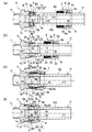
本発明のホース継手Aの実施形態は、図1〜図4に示す如く、可撓性ホースHの接続端部が挿入されるニップル1と、このニップル1に対して軸方向へ往復動自在に設けられる締め付け具2と、ニップル1の外周面にホースHの接続端部を介して配置される拡縮スリーブ3とを備え、ニップル1の外周面にホースHの接続端部が挿入された後に、締め付け具2を軸方向、例えばホースHの挿入方向(以下ホース挿入方向という)へ移動させて拡縮スリーブ3を縮径することにより、このホースHの接続端部の内周面H1がニップル1の外周面に密着されて該ホースHを引き抜き不能に接続するものである。
The embodiment of the hose joint A of the present invention is, as shown in FIGS. 1 to 4, a
ニップル1は、例えば真鍮などの金属や硬質合成樹脂などの硬質材料で、ホースHの内径と略同じか又はそれよりも若干大きい外径を有する円筒状に形成するか、或いは例えばステンレスなどの変形可能な剛性材料からなる板材をプレス加工やその他の成形加工することで肉厚が薄い円筒状に形成され、その外周面には、ホース挿入方向へ徐々に拡径してその最大径部分から徐々に縮径するように形成される環状の膨出部1aが形成されている。
The
環状の膨出部1aは、ニップル1のホース挿入方向と逆方向(以下反挿入方向という)の先端縁1bからホース挿入方向へ徐々に拡径する拡径面1a1と、拡径面1a1の最大径部分からホース挿入方向へ徐々に縮径する縮径面1a2とを連続状に配置しており、図1〜図4に示される例では、直線状に傾斜するテーパー面としているが、その他の例として曲面状に傾斜させることも可能である。
膨出部1aの縮径面1a2よりもホース挿入方向奥側には、縮径面1aの最小径部分と同径の奥側外周面1cが、ホース挿入方向に所定長さ形成されている。
The annular bulging
On the back side in the hose insertion direction from the reduced diameter surface 1a2 of the bulging
ニップル1の先端内周面には、その先端へ向けて徐々に拡径する逆テーパー面1dを形成し、図1(d)に示される例では、後述する締め付け具2による締め付け状態でニップル1の先端縁1bよりも後述する押圧筒部4を突出させることにより、押圧筒部4でホースHが内方へ押されて、その内端部分がニップル1の逆テーパー面1dと連続するように配置することが好ましい。
On the inner peripheral surface of the tip of the
また、ニップル1の奥側外周面1cよりもホース挿入方向奥側には、この奥側外周面1cからほぼ垂直に突出する環状段部1eが一体形成され、この環状段部1eの外側には、後述する締め付け具2をホース挿入方向及びホース挿入方向と反挿入方向へ往復動自在に支持するためのスライド手段1fが形成されている。
さらに、ニップル1の外周面には、回転操作用の滑り止め手段1gとして、例えば図2及び図4に示される例のように、工具などが係合する平面部を周方向へ適宜間隔毎に複数形成したり、その他にローレットなどの凹凸部を形成することが好ましい。
Further, an
Further, on the outer peripheral surface of the
締め付け具2は、ニップル1と同種又は異種の材料でホースHの外径よりも大きい内径を有する略円筒状に形成され、その内周面には、ニップル1のスライド手段1fと係合してホース挿入方向及び反挿入方向へ往復動自在に支持するためのスライド手段2aが形成される。
これらニップル1のスライド手段1f及び締め付け具2のスライド手段2aとしては、ニップル1に対し締め付け具2を相対的に回転操作することでホース挿入方向及び反挿入方向へ相対的に往復動させるネジを形成することが好ましい。
また、その他の例として、ニップル1と締め付け具2を面接触させてホース挿入方向へ移動することにより、凹凸嵌合して両者が移動不能に係止されるようにすることも可能である。
The
As the sliding
As another example, the
さらに、締め付け具2の内側には、ニップル1に対する締め付け具2の軸方向移動に伴って後述する拡縮スリーブ3の筒状拡縮部3eを径方向へ加圧し縮径させる手段が設けられる。
このスリーブ縮径手段としては、締め付け具2の内周面に、反挿入方向へ向けて内径が徐々に小径となるテーパー状に傾斜する押圧面部2bを直接形成することが好ましい。
また、その他の例として、締め付け具2の内側(内周)に押圧スリーブを回転自在に設け、この押圧スリーブの内周面を、後述する拡縮スリーブ3の筒状拡縮部3eの外周面と対向して、反挿入方向へ向けて内径が徐々に小径となるテーパー状に傾斜する押圧面部とすることも可能である。
Further, inside the
As the sleeve diameter-reducing means, it is preferable to directly form the
As another example, a pressing sleeve is rotatably provided on the inner side (inner periphery) of the
締め付け具2の内周面において反挿入方向の一端側には、締め付け具2の軸方向移動に伴って膨出部1aの拡径面1a1と対向するように形成される押圧筒部4を別体又は一体に設け、締め付け具2の軸方向移動による締め付け状態で、押圧筒部4のホース挿入方向側端面、すなわち奥側端面4aと、後述する拡縮スリーブ3の反ホース挿入方向側端面、すなわち入口側端面3bとの間に形成される環状空間Sと対向するように係合凹部2cを形成することが好ましい。
On one end side in the anti-insertion direction on the inner peripheral surface of the
また、締め付け具2の外周面には、回転操作用の滑り止め手段2dとして、例えば図2及び図4に示される例のように、工具などが係合する平面部を周方向へ適宜間隔毎に複数形成したり、その他にローレットなどの凹凸部を形成することが好ましい。
Further, on the outer peripheral surface of the
拡縮スリーブ3は、例えばポリアセタール樹脂やそれ以外の表面の滑り性と耐熱性に優れた合成樹脂などの弾性変形可能な材料で略円筒状に形成され、ニップル1の環状段部1eに挿着することで、ニップル1の縮径面1a2及び奥側外周面1cと対向するように配置され、特に縮径面1a2と対向するホース挿入方向と逆側部分を入口部3aとしている。
さらに、拡縮スリーブ3は、図1(a)〜(c)に示されるようにホースHの挿入前の時点及び挿入時には拡径変形しており、その少なくとも入口部3aの内径を、膨出部1aの縮径面1a2に沿って挿入されるホースHの外径よりも大きくなるように設定し、また図1(d)に示されるように締め付け具2の軸方向移動に伴い押圧面部2bで押圧された時には縮径変形して、入口部3aの内径を、膨出部1aの縮径面1a2に沿って挿入されたホースHの外径よりも小さくなるように設定している。
The expansion /
Further, as shown in FIGS. 1A to 1C, the expansion /
このようなホース継手Aによると、ホースHの挿入時には図1(a)(b)に示されるように、ホースHの先端部が拡縮スリーブ3の入口部3aに突き当たることなく拡縮スリーブ3と縮径面1a2との間にスムーズに入り込んで定位置まで挿入可能となる。
その後、締め付け具2の軸方向移動に伴い押圧面部2bで押圧された時には図1(d)に示されるように、拡縮スリーブ3が縮径変形して、その入口部3aとニップル1の縮径面1a2との間にホースHが径方向へ挟み込まれる。
According to such a hose joint A, when the hose H is inserted, as shown in FIGS. 1A and 1B, the tip of the hose H does not hit the
Thereafter, when the
この際、締め付け具2の内周面に押圧筒部4が別体又は一体に設けられる場合には、締め付け具2の軸方向移動により膨出部1aの拡径面1a1と押圧筒部4との間にホースHが径方向へ挟み込まれると同時に、これに伴いホースHの外周面H2が、押圧筒部4のホース挿入方向側端面(奥側端面)4aと、拡縮スリーブ3の反ホース挿入方向側端面(入口側端面)3bとの間に形成される環状空間Sを通って係合凹部2cへ向けて膨出変形し、それにより膨出変形したホースHの外周面H2が係合凹部2cに沿って密着し圧接する。
At this time, when the
更に詳しく説明すれば、拡縮スリーブ3は、反挿入方向に向けて徐々に拡径するように形成され、その軸方向へ延びるすり割り3cを切欠形成して径方向へ弾性変形可能にするとともに、その入口部3aにはホースHの外周面H2と対向する環状の凸部を形成し、この環状の凸部の内径を、ホースHの挿入前及び挿入時には膨出部1aの縮径面1a2に沿って挿入されるホースHの外径よりも大きくなるようにし、また締め付け具2の軸方向移動に伴い押圧面部2bで拡縮スリーブ3が押圧された時には、環状の凸部の内径を、膨出部1aの縮径面1a2に沿って挿入されたホースHの外径よりも小さくなるように設定している。
つまり、拡縮スリーブ3のホース挿入方向奥側における内径を、膨出部1bの縮径面1b2に沿って挿入されるホースHの外径と略同じに設定して、締め付け具2の軸方向移動に伴い押圧面部2bで拡縮スリーブ3が押圧された時には、入口部3aとなる環状の凸部がホースHの外周面H2に食い込み、その他の内周面3dがホースHの外周面H2に圧接するようにしている。
More specifically, the expansion /
That is, the inner diameter of the expansion /
このようなホース継手Aによると、ホースHの挿入時には図1(a)(b)に示されるように、拡縮スリーブ3の入口部3aとなる環状の凸部に対して、ホースHの先端部が突き当たることなく、拡縮スリーブ3の内周面3dと縮径面1a2及びニップル1の奥側外周面1cとの間にスムーズに挿入される。
その後、締め付け具2の軸方向移動に伴い押圧面部2bで押圧された時には図1(d)に示されるように、拡縮スリーブ3が縮径変形して内周面3dとニップル1の奥側外周面1cとの間にホースHが挟み込まれると同時に、その入口部3aとなる環状の凸部がホースHの外周面H2に食い込んでニップル1の縮径面1a2との間に更に強く挟み込まれる。
以下、本発明の一実施例を図面に基づいて説明する。
According to such a hose joint A, when the hose H is inserted, as shown in FIGS. 1 (a) and 1 (b), the tip of the hose H is opposed to the annular convex portion serving as the
Thereafter, when the
Hereinafter, an embodiment of the present invention will be described with reference to the drawings.
この実施例1は、図1(a)〜(d),図2(a)〜(d),図3及び図4(a)(b)に示すように、ニップル1のスライド手段1fとして外ネジ部を刻設し、これと対向する締め付け具2のスライド手段2aとして内ネジ部を刻設し、これら外ネジ部1f及び内ネジ部2aを螺合させ、ニップル1に対し締め付け具2を回転操作してホース挿入方向へ移動させることにより、締め付け具2の内周面に一体形成した押圧面部2bが、拡縮スリーブ3の入口部3aを押圧して縮径変形させるようにしている。
As shown in FIGS. 1 (a) to (d), FIGS. 2 (a) to (d), FIGS. 3 and 4 (a) and (b), the first embodiment is used as a sliding
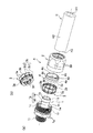
この拡縮スリーブ3は、図4(a)(b)に示すように、その入口部3aとなる環状の凸部、反ホース挿入方向側端面(入口側端面)3b及び内周面3dを有する筒状拡縮部3eと、この筒状拡縮部3eのホース挿入方向の他端からニップル1の奥側外周面1cに向けて一体形成される環状鍔部3fとからなり、この環状鍔部3fを、ホースHの先端面(切断面)H3の突き当たり面として使用するとともに、すり割り3cが周方向へ複数切欠形成される。
これらすり割り3cのうち一本のすり割り3c1を筒状拡縮部3e及び環状鍔部3fに亘り連続させているが、他のすり割り3c2は筒状拡縮部3e又は環状鍔部3fに部分的に形成している。
As shown in FIGS. 4 (a) and 4 (b), the expansion /
Of these
さらに、拡縮スリーブ3における筒状拡縮部3eの外周面には、ニップル1のスライド手段1fとなる外ネジ部の先端縁1hと対向するストッパー3gが一体的に突出形成されている。
ここで、このストッパー3gから環状鍔部3fまでの軸方向寸法と、ニップル1の外ネジ部1fの先端縁1hから環状段部1eまでの軸方向寸法とが一致するように予め設定しておけば、ストッパー3gを外ネジ部1fの先端縁1hに当接させることにより、ニップル1の環状段部1eに対して拡縮スリーブ3の環状鍔部3fが当接するように位置決めされるとともに、拡縮スリーブ3のセット時において、ストッパー3gと外ネジ部1fの先端縁1hとの位置関係、例えば両者のガタ付き具合を見るだけで、環状鍔部3fがニップル1の環状段部1eと当接するように正しく組み付けられているか否かを判断可能になる。
また、ホースHの先端面H3を拡縮スリーブ3の環状鍔部3fに突き当てながら挿入することにより、ストッパー3gと外ネジ部1fの先端縁1hとのガタ付き具合で、ホースHが目的位置まで確実に挿入されたことを簡単に感知することができるとともに、ホースHの挿入に伴い拡縮スリーブ3が変形して破損することを防止できる。
Furthermore, a
Here, the axial dimension from the
Further, by inserting the front end surface H3 of the hose H against the
そして、この実施例1では、ニップル1に対して締め付け具2が相対的に回転するため、前述した押圧筒部4として締め付け具2と別体のリングが用いられる。
この押圧筒部4となる別体のリングは、図4(a)に示される例の場合、その軸方向全長に延びるすり割り4bを切欠形成して径方向へ弾性変形可能にし、該リングの外周面4c及びそれと対向する締め付け具2の内周面の両方又はいずれか一方には、別体のリング4が縮径するように押圧するテーパー面4d,2eを形成し、この縮径された状態における内径を、膨出部1aの拡径面1a1に沿って挿入されるホースHの外径よりも小さくなるように設定している。
また、その他の例として押圧筒部4を、すり割りが無いリング状に成形し、縮径変形させることなく、ホースHを膨出部1aの拡径面1a1に押圧させるようにすることも可能である。
In the first embodiment, since the
In the case of the example shown in FIG. 4 (a), the separate ring that becomes the
Further, as another example, the
また、ニップル1のスライド手段1fとして形成される外ネジ部よりもホース挿入方向奥側には、他の機器の管接続口(図示せず)に接続するための接続部1iが連設される。 この接続部1iは、斯かるホース継手Aに接続する他の機器における管接続口の内周面に内ネジが刻設される場合には、これと対応する外ネジを刻設し、また該管接続口の外周面に外ネジが刻設される場合には、これと対応する内ネジを刻設している。
図示される例ではニップル1が、円筒材料を例えば切削加工などで削り出した切削品であり、接続部1iとして外ネジが刻設されている。
Further, a connecting
In the illustrated example, the
一方、ホースHは、例えばシリコーンゴムや塩化ビニルなどの軟質合成樹脂などの軟質材料で構成され、その内周面H1と外周面H2が平坦なものが好ましい。
その具体例としては、その透明又は不透明な外層と内層との間に中間層として、複数本か又は単数本の合成樹脂製ブレード(補強糸)が螺旋状に埋設される積層ホースや、中間層として合成樹脂製又は金属製の断面矩形などの帯状補強材と断面円形などの線状補強材を螺旋状に巻き付けて一体化した螺旋補強ホースや、例えばガラス繊維や難燃性繊維などの糸状補強材をホース外周面に編組した編組補強ホースや、金属製線材や硬質合成樹脂製線材を螺旋状に埋設した螺旋補強ホースや、単層構造の軟質合成樹脂製ホースなどが用いられる。
On the other hand, the hose H is preferably made of a soft material such as a soft synthetic resin such as silicone rubber or vinyl chloride, and the inner peripheral surface H1 and the outer peripheral surface H2 are flat.
Specific examples thereof include a laminated hose in which a plurality or a single synthetic resin blade (reinforcing yarn) is spirally embedded as an intermediate layer between the transparent or opaque outer layer and inner layer, and an intermediate layer As a spiral reinforcement hose in which a strip-shaped reinforcing material made of synthetic resin or metal, such as a rectangular cross section, and a linear reinforcing material, such as a circular cross section, are spirally wound and integrated, for example, fiber reinforcement such as glass fiber or flame-retardant fiber A braided reinforcement hose in which a material is braided on the outer peripheral surface of the hose, a spiral reinforcement hose in which a metal wire or a hard synthetic resin wire is embedded spirally, a soft synthetic resin hose having a single layer structure, or the like is used.
次に、斯かるホース継手AによるホースHの接続方法を工程順に従って説明し、それにより得られる作用効果についても説明する。
図3及び図4(a)(b)に示すホース継手Aの分解状態から、図1(a)及び図2(a)に示すように、先ず、ニップル1の環状段部1e及び奥側外周面1cに対して拡縮スリーブ3がニップル1の膨出部1aを乗り越えながらセットされると、これら奥側外周面1cと拡縮スリーブ3の内周面3bとの間にホースHの挿入空間が形成される。
また、ホースHを締め付け具2及び押圧筒部4となる別体のリングに挿通し、その後、このホースHの先端部をホースHの挿入空間へ向けニップル1の膨出部1aに沿って挿入開始する。
Next, the connection method of the hose H by such a hose coupling A will be described according to the order of steps, and the effects obtained thereby will also be described.
From the disassembled state of the hose joint A shown in FIGS. 3 and 4 (a) and 4 (b), as shown in FIGS. 1 (a) and 2 (a), first, the
Further, the hose H is inserted into a separate ring that serves as the
この時点では、拡縮スリーブ3の入口部3aとなる環状の凸部が、膨出部1aの縮径面1a2に沿って挿入されるホースHの外径よりも大きくなるように拡径変形しているため、この環状の凸部にホースHの先端部が突き当たることなく、拡縮スリーブ3の内周面3dと縮径面1a2及びニップル1の奥側外周面1cとの間にスムーズに挿入され、図1(b)及び図2(b)に示すように、ホースHの先端面H3が拡縮スリーブ3の環状鍔部3fを介してニップル1の環状段部1eに突き当たって、それ以上のホースHが挿入不能になる。
At this time, the ring-shaped convex portion that becomes the
次に、締め付け具2をホース挿入方向へ移動して、図1(c)及び図2(c)に示すように、その内ネジ部2aをニップル1の外ネジ部1fに螺合させ、締め付け具2の回転操作しても、押圧筒部4となる別体のリングとスリップして、その回転力が該リングを介してホースHに伝わることがなく、ホースHの捻れが防止される。
これに伴い、リングの内周面4eが、膨出部1aの拡径面1a1に沿って挿入されたホースHの外周面H2と強く接触するため、これら締め付け具2の内周面とリングの外周面4cとの間にズレが発生してテーパー面4d,2eによりリングが縮径変形する。
これにより、それ以降は締め付け具2の移動によりリングの内周面4eがホースHの外周面H2に対し更に強く圧接してホース挿入方向へ引き寄せるように力が発生するとともに、拡縮スリーブ3の反ホース挿入方向側端面(入口側端面)3bとの間隔が徐々に狭くなる。
Next, the
Along with this, the inner
As a result, a force is generated so that the inner
さらに、締め付け具2のホース挿入方向の移動により、押圧面部2bが拡縮スリーブ3の筒状拡縮部3eに当接して径方向へ加圧するため、図1(d)及び図2(d)に示すように、拡縮スリーブ3の筒状拡縮部3eが縮径変形して、その入口部3aとなる環状の凸部と、膨出部1aの縮径面1a2との間にホースHが挟み込まれ、この環状の凸部3aがホースHの外周面H2に食い込み、その他の内周面3dがホースHの外周面H2に圧接する。
そして、これと同時に、押圧筒部4となる別体のリングの内周面4eがホースHの外周面H2に食い込んで、膨出部1aの拡径面1a1と押圧筒部4との間にホースHが径方向へ挟み込まれる。
Furthermore, since the
At the same time, the inner
それにより、ホースHの外周面H2が、押圧筒部4となる別体のリングのホース挿入方向側端面(奥側端面)4aと、拡縮スリーブ3の反ホース挿入方向側端面(入口側端面)3bとの間に形成される環状空間Sを通って係合凹部2cへ向けて膨出変形し、この膨出変形したホースHの外周面H2は係合凹部2cに沿って密着し圧接する。
特にホースHが例えばシリコーンホースのように柔らかく変形し易い場合には、このような環状の凸部3aや押圧筒部4となる別体のリングの内周面4eの食い込み及び拡縮スリーブ3の内周面3dの圧接により、その圧縮分だけホースHの外周面H2が膨出して、リングのホース挿入方向側端面(奥側端面)4aと、拡縮スリーブ3の反ホース挿入方向側端面(入口側端面)3bとの間に強く挟み込まれるため、ホースHが軸方向及び径方向へ確実に挟持され、ホース先端の押し込み位置を安定化しながらニップル1の外周面とホースHとのシール性及び抜け強度を高めることができる。
Thereby, the outer peripheral surface H2 of the hose H is a hose insertion direction side end surface (rear side end surface) 4a of a separate ring to be the
In particular, when the hose H is soft and easily deformed, for example, like a silicone hose, the inner
なお、前示実施例では、ニップル1に対し締め付け具2を軸方向移動させるスライド手段1f,2aとして互いに螺合する外ネジ部と内ネジ部を形成したが、これに限定されず、少なくとも拡縮スリーブ3に対して締め付け具2を軸方向移動させることができれば、ネジ以外の構造であっても良い。
In the embodiment shown above, the outer screw portion and the inner screw portion that are screwed to each other are formed as the slide means 1f and 2a that move the
1 ニップル 1a 膨出部
1a1 拡径面 1a2 縮径面
1c 奥側外周面 2 締め付け具
2b 押圧面部 2c 係合凹部
3 拡縮スリーブ 3a 入口部
3b 反ホース挿入方向側端面(入口側端面)
3c すり割り 3d 内周面
3f 環状鍔部 4 押圧筒部
4a ホース挿入方向側端面(奥側端面)
H ホース H1 内周面
H2 外周面 H3 先端面
DESCRIPTION OF
H hose H1 inner peripheral surface H2 outer peripheral surface H3 tip surface
Claims (3)
ホース挿入方向へ徐々に拡径する拡径面及びその最大径部分から徐々に縮径する縮径面を有する環状の膨出部が外周面に形成される前記ニップルと、
前記膨出部の縮径面及び該縮径面よりもホース挿入方向奥側に位置する奥側外周面と対向して設けられる径方向へ弾性変形可能な拡縮スリーブと、
前記拡縮スリーブの外周面と対向して設けられ、前記ニップルに対する軸方向移動に伴って前記拡縮スリーブを縮径させるように押圧する押圧面部が内側に形成される前記締め付け具とを備え、
前記ニップルは、前記膨出部の縮径面よりもホース挿入方向奥側に形成される奥側外周面と、前記奥側外周面よりもホース挿入方向奥側に突出形成される環状段部と、前記環状段部の外側に前記奥側外周面と対向して形成される筒状部とを有し、
前記拡縮スリーブは、前記縮径面と対向するように形成される入口部と、該入口部よりもホース挿入方向奥側において前記奥側外周面と対向するように形成される筒状拡縮部と、前記筒状拡縮部のホース挿入方向奥側端から前記奥側外周面に向け前記環状段部に沿って前記ホースの先端面と対向するように形成される環状鍔部と、前記筒状拡縮部の外周面に前記筒状部の先端縁と対向して当接するように突出形成されるストッパーとを有し、
前記入口部及び前記筒状拡縮部の内径を、前記ホースの挿入時には、前記膨出部の縮径面に沿って挿入される前記ホースの外径よりも大きくなるように設定し、また前記締め付け具の軸方向移動に伴い前記押圧面部で前記拡縮スリーブが押圧された時には、前記膨出部の縮径面に沿って挿入される前記ホースの外径よりも小さくなるように設定し、
前記ストッパーのホース挿入方向奥側突出面から前記環状鍔部のホース挿入方向奥側端までの軸方向寸法と、前記筒状部の先端縁から前記環状段部までの軸方向寸法とが一致するように設定したことを特徴とするホース継手。 A hose joint in which a hose is inserted along the outer peripheral surface of the nipple, and the inner peripheral surface of the hose is in close contact with the outer peripheral surface of the nipple by the axial movement of a fastening tool provided outside the nipple,
It said nipple bulged portion of the annular having a reduced diameter surface gradually reduced in diameter from the diameter expansion surface and a maximum diameter portion gradually enlarged to hose insertion direction is formed on the outer peripheral surface,
An expansion / contraction sleeve that is elastically deformable in the radial direction and is provided opposite to the diameter-reduced surface of the bulging portion and the outer peripheral surface located on the rear side in the hose insertion direction than the diameter-reduced surface;
Provided face the outer peripheral surface of the front Symbol scaling sleeve, and said clamp pressing face is formed on the inside for pressing in so that reducing the diameter of the scaling sleeve with the axial movement against the nipple Prepared,
The nipple includes a rear outer peripheral surface formed on the back side in the hose insertion direction with respect to the diameter-reduced surface of the bulging portion, and an annular stepped portion formed to protrude from the back outer peripheral surface on the rear side in the hose insertion direction. A cylindrical portion formed on the outer side of the annular step portion so as to face the outer peripheral surface,
The expansion / contraction sleeve includes an inlet portion formed so as to face the reduced diameter surface, and a cylindrical expansion / contraction portion formed so as to face the outer peripheral surface on the back side in the hose insertion direction from the inlet portion. An annular flange portion formed so as to face the front end surface of the hose along the annular stepped portion from the rear end in the hose insertion direction of the cylindrical expansion / contraction portion toward the outer peripheral surface, and the cylindrical expansion / contraction A stopper that protrudes and abuts against the distal end edge of the cylindrical portion on the outer peripheral surface of the cylindrical portion,
The inner diameter of the inlet part and the cylindrical expansion / contraction part is set to be larger than the outer diameter of the hose inserted along the reduced diameter surface of the bulging part when the hose is inserted, and the tightening When the expansion / contraction sleeve is pressed by the pressing surface portion along with the axial movement of the tool, it is set to be smaller than the outer diameter of the hose inserted along the reduced diameter surface of the bulging portion ,
The axial dimension from the hose insertion direction back side protrusion surface of the stopper to the hose insertion direction back end of the annular flange matches the axial dimension from the tip edge of the cylindrical part to the annular step part. A hose coupling characterized by being set as follows.
Priority Applications (4)
| Application Number | Priority Date | Filing Date | Title |
|---|---|---|---|
| JP2009202862A JP4868371B2 (en) | 2009-09-02 | 2009-09-02 | Hose fittings |
| CN201080039029.0A CN102575801B (en) | 2009-09-02 | 2010-09-01 | Hose joint |
| PCT/JP2010/064887 WO2011027766A1 (en) | 2009-09-02 | 2010-09-01 | Hose joint |
| MYPI2012000900A MY162527A (en) | 2009-09-02 | 2010-09-01 | Hose joint |
Applications Claiming Priority (1)
| Application Number | Priority Date | Filing Date | Title |
|---|---|---|---|
| JP2009202862A JP4868371B2 (en) | 2009-09-02 | 2009-09-02 | Hose fittings |
Publications (3)
| Publication Number | Publication Date |
|---|---|
| JP2011052772A JP2011052772A (en) | 2011-03-17 |
| JP2011052772A5 JP2011052772A5 (en) | 2011-11-04 |
| JP4868371B2 true JP4868371B2 (en) | 2012-02-01 |
Family
ID=43649301
Family Applications (1)
| Application Number | Title | Priority Date | Filing Date |
|---|---|---|---|
| JP2009202862A Active JP4868371B2 (en) | 2009-09-02 | 2009-09-02 | Hose fittings |
Country Status (4)
| Country | Link |
|---|---|
| JP (1) | JP4868371B2 (en) |
| CN (1) | CN102575801B (en) |
| MY (1) | MY162527A (en) |
| WO (1) | WO2011027766A1 (en) |
Families Citing this family (13)
| Publication number | Priority date | Publication date | Assignee | Title |
|---|---|---|---|---|
| DE102010049380A1 (en) * | 2010-10-26 | 2012-04-26 | Michael Meier | hose coupling |
| JP5747207B2 (en) * | 2013-07-05 | 2015-07-08 | 株式会社潤工社 | Pipe fitting |
| JP5849261B2 (en) * | 2013-08-30 | 2016-01-27 | 株式会社トヨックス | Pipe fitting |
| MY183191A (en) * | 2013-08-30 | 2021-02-18 | Toyox Kk | Tube joint |
| JP5799326B2 (en) * | 2013-08-30 | 2015-10-21 | 株式会社トヨックス | Pipe fitting |
| JP2015052344A (en) * | 2013-09-06 | 2015-03-19 | 本田技研工業株式会社 | Hose attachment structure |
| US9657656B2 (en) * | 2014-08-27 | 2017-05-23 | Continental Automotive Systems, Inc. | Idle air control valve for use in a small engine and having a protective shroud with valve seat |
| JP6078857B2 (en) * | 2015-08-27 | 2017-02-15 | 株式会社トヨックス | Pipe fitting |
| CN106820530A (en) * | 2016-12-30 | 2017-06-13 | 重庆鹏旭新能源有限公司 | A kind of water heater integration formula shampoo trap |
| JP2019002462A (en) * | 2017-06-14 | 2019-01-10 | 株式会社カネカ | Tube joint |
| CN107504304A (en) * | 2017-09-01 | 2017-12-22 | 全球能源互联网研究院 | A kind of change current valve module FEP hose joint assemblies |
| DK3706598T3 (en) * | 2017-11-09 | 2022-04-04 | Oelschlaeger Metalltechnik Gmbh | Telescopic column, in particular for furniture, such as tables, and table with such a column |
| WO2020211961A1 (en) * | 2019-04-18 | 2020-10-22 | Husqvarna Ab | Hose connector |
Family Cites Families (6)
| Publication number | Priority date | Publication date | Assignee | Title |
|---|---|---|---|---|
| US4900068A (en) * | 1988-12-19 | 1990-02-13 | Heyco Molded Products, Inc. | Liquid tight connector for flexible non-metallic conduit and flexible non-metallic tubing |
| JPH0431066Y2 (en) * | 1989-12-28 | 1992-07-27 | ||
| JP3325086B2 (en) * | 1993-06-28 | 2002-09-17 | 株式会社トヨックス | Hose fittings |
| KR980008820U (en) * | 1996-07-10 | 1998-04-30 | 박강훈 | Synthetic hose connection |
| JP3543215B2 (en) * | 1999-07-28 | 2004-07-14 | ニッタ・ムアー株式会社 | Pipe fittings |
| JP3088531U (en) * | 2002-03-12 | 2002-09-20 | 株式会社リガルジョイント | Hose joint connection structure |
-
2009
- 2009-09-02 JP JP2009202862A patent/JP4868371B2/en active Active
-
2010
- 2010-09-01 CN CN201080039029.0A patent/CN102575801B/en not_active Expired - Fee Related
- 2010-09-01 WO PCT/JP2010/064887 patent/WO2011027766A1/en active Application Filing
- 2010-09-01 MY MYPI2012000900A patent/MY162527A/en unknown
Also Published As
| Publication number | Publication date |
|---|---|
| MY162527A (en) | 2017-06-15 |
| WO2011027766A1 (en) | 2011-03-10 |
| CN102575801A (en) | 2012-07-11 |
| JP2011052772A (en) | 2011-03-17 |
| CN102575801B (en) | 2014-07-23 |
Similar Documents
| Publication | Publication Date | Title |
|---|---|---|
| JP4868371B2 (en) | Hose fittings | |
| WO2013115044A1 (en) | Pipe joint | |
| JP2011052772A5 (en) | ||
| JP2008240881A (en) | Hose joint | |
| WO2013172138A1 (en) | Tube joint | |
| JP2008095765A (en) | Hose joint | |
| JP2008286259A (en) | Pipe joint | |
| JP5537982B2 (en) | Pipe fitting | |
| US9121530B2 (en) | Tube fitting assembly | |
| JP6078857B2 (en) | Pipe fitting | |
| JP2011069484A (en) | Hose joint | |
| JP5849261B2 (en) | Pipe fitting | |
| JP2008138694A (en) | Pipe joint | |
| JP5268100B2 (en) | Pipe fitting | |
| JP2009115154A (en) | Tube coupling and method of constructing the same | |
| GB2471502A (en) | A universal compression-type pipe coupling | |
| JP2010127461A (en) | Resin pipe joint | |
| JP2009287646A (en) | Pipe joint | |
| JP5799326B2 (en) | Pipe fitting | |
| JP2013029193A (en) | Pipe coupling | |
| JP5098101B2 (en) | Pipe fitting | |
| JP4751920B2 (en) | Resin pipe fitting | |
| JP5112216B2 (en) | Resin pipe fitting | |
| JP2016080107A (en) | Connection structure for joint and hose, and connection structure for joint and pipe | |
| JP4914910B2 (en) | Resin pipe fitting |
Legal Events
| Date | Code | Title | Description |
|---|---|---|---|
| A521 | Request for written amendment filed |
Free format text: JAPANESE INTERMEDIATE CODE: A523 Effective date: 20110920 |
|
| A621 | Written request for application examination |
Free format text: JAPANESE INTERMEDIATE CODE: A621 Effective date: 20110920 |
|
| A871 | Explanation of circumstances concerning accelerated examination |
Free format text: JAPANESE INTERMEDIATE CODE: A871 Effective date: 20110920 |
|
| A975 | Report on accelerated examination |
Free format text: JAPANESE INTERMEDIATE CODE: A971005 Effective date: 20111004 |
|
| TRDD | Decision of grant or rejection written | ||
| A01 | Written decision to grant a patent or to grant a registration (utility model) |
Free format text: JAPANESE INTERMEDIATE CODE: A01 Effective date: 20111011 |
|
| A01 | Written decision to grant a patent or to grant a registration (utility model) |
Free format text: JAPANESE INTERMEDIATE CODE: A01 |
|
| A61 | First payment of annual fees (during grant procedure) |
Free format text: JAPANESE INTERMEDIATE CODE: A61 Effective date: 20111108 |
|
| R150 | Certificate of patent or registration of utility model |
Ref document number: 4868371 Country of ref document: JP Free format text: JAPANESE INTERMEDIATE CODE: R150 Free format text: JAPANESE INTERMEDIATE CODE: R150 |
|
| FPAY | Renewal fee payment (event date is renewal date of database) |
Free format text: PAYMENT UNTIL: 20141125 Year of fee payment: 3 |
|
| R250 | Receipt of annual fees |
Free format text: JAPANESE INTERMEDIATE CODE: R250 |
|
| R250 | Receipt of annual fees |
Free format text: JAPANESE INTERMEDIATE CODE: R250 |
|
| R250 | Receipt of annual fees |
Free format text: JAPANESE INTERMEDIATE CODE: R250 |
|
| R250 | Receipt of annual fees |
Free format text: JAPANESE INTERMEDIATE CODE: R250 |
|
| R250 | Receipt of annual fees |
Free format text: JAPANESE INTERMEDIATE CODE: R250 |
|
| R250 | Receipt of annual fees |
Free format text: JAPANESE INTERMEDIATE CODE: R250 |
|
| R250 | Receipt of annual fees |
Free format text: JAPANESE INTERMEDIATE CODE: R250 |
|
| R250 | Receipt of annual fees |
Free format text: JAPANESE INTERMEDIATE CODE: R250 |
|
| R250 | Receipt of annual fees |
Free format text: JAPANESE INTERMEDIATE CODE: R250 |
|
| R250 | Receipt of annual fees |
Free format text: JAPANESE INTERMEDIATE CODE: R250 |