WO2011027766A1 - Hose joint - Google Patents
Hose joint Download PDFInfo
- Publication number
- WO2011027766A1 WO2011027766A1 PCT/JP2010/064887 JP2010064887W WO2011027766A1 WO 2011027766 A1 WO2011027766 A1 WO 2011027766A1 JP 2010064887 W JP2010064887 W JP 2010064887W WO 2011027766 A1 WO2011027766 A1 WO 2011027766A1
- Authority
- WO
- WIPO (PCT)
- Prior art keywords
- hose
- diameter
- peripheral surface
- nipple
- sleeve
- Prior art date
Links
Images

Classifications
-
- F—MECHANICAL ENGINEERING; LIGHTING; HEATING; WEAPONS; BLASTING
- F16—ENGINEERING ELEMENTS AND UNITS; GENERAL MEASURES FOR PRODUCING AND MAINTAINING EFFECTIVE FUNCTIONING OF MACHINES OR INSTALLATIONS; THERMAL INSULATION IN GENERAL
- F16L—PIPES; JOINTS OR FITTINGS FOR PIPES; SUPPORTS FOR PIPES, CABLES OR PROTECTIVE TUBING; MEANS FOR THERMAL INSULATION IN GENERAL
- F16L33/00—Arrangements for connecting hoses to rigid members; Rigid hose connectors, i.e. single members engaging both hoses
- F16L33/22—Arrangements for connecting hoses to rigid members; Rigid hose connectors, i.e. single members engaging both hoses with means not mentioned in the preceding groups for gripping the hose between inner and outer parts
- F16L33/223—Arrangements for connecting hoses to rigid members; Rigid hose connectors, i.e. single members engaging both hoses with means not mentioned in the preceding groups for gripping the hose between inner and outer parts the sealing surfaces being pressed together by means of a member, e.g. a swivel nut, screwed on or into one of the joint parts
- F16L33/224—Arrangements for connecting hoses to rigid members; Rigid hose connectors, i.e. single members engaging both hoses with means not mentioned in the preceding groups for gripping the hose between inner and outer parts the sealing surfaces being pressed together by means of a member, e.g. a swivel nut, screwed on or into one of the joint parts a clamping ring being arranged between the threaded member and the connecting member
Definitions
- the present invention relates to a hose coupling used for piping connection of a soft and deformable hose such as silicone rubber. More specifically, the present invention relates to a hose joint in which a hose is inserted along the outer peripheral surface of a nipple and the inner peripheral surface of the hose is in close contact with the outer peripheral surface of the nipple by axial movement of a fastener provided on the outer side.
- a front connected between a nut connected to a second joint configured as a nipple and an inner peripheral surface of a female screw of the nut and an outer peripheral surface of a hose tip The inner side of the hose end in a state of being connected to the ring, the back ring interposed between the rear end inner peripheral surface of the nut and the outer peripheral surface of the hose spaced apart from the front ring by a predetermined distance, and the second joint
- an insert sleeve which is fitted into a circumferential surface and which holds an inner and outer peripheral surface on the end of the hose together with a front ring or a buckling (see, for example, Patent Document 1).
- the buckling is drawn to the front ring side, and the outer periphery of the hose externally fitted on the annular convex portion of the insert sleeve or the both curved slopes is the front ring.
- a portion which is radially expanded and deformed by the annular convex portion is clamped in the axial direction by the front ring or the buckling.
- the fitting cylinder outer periphery of the insert sleeve is fluid-tightly fitted to the large diameter stepped fitting hole of the second joint via the O ring,
- the fluid that has entered the gap between the communication hole of the insert sleeve and the communication hole of the second joint is also in contact with (is in contact with) the O-ring, which tends to be unsanitary, resulting in a problem that the application is limited. Therefore, the insert sleeve and the second joint are integrated in advance, the hose is inserted along the annular convex portion of the insert sleeve, and the end portion of the hose is inserted into the front ring which stands by at the fixed position.
- An object of the present invention is to address such problems, and to stabilize the pressing position of the tip of the hose to enhance the sealing performance and the detachment strength between the outer peripheral surface of the nipple and the hose, and the outer periphery of the nipple.
- the object of the invention is to further improve the sealing property and removal strength between the surface and the hose, to reliably clamp the hose in the axial direction and the radial direction, and to reliably insert the hose to a fixed position.
- the hose is inserted along the outer peripheral surface of the nipple, and the inner peripheral surface of the hose is the outer periphery of the nipple by the axial movement of the clamp provided on the outer side.
- a radially expandable resiliently contracting sleeve which is provided opposite to the diameter reducing surface of the bulged portion, and which is formed on the inner side of the fastener against the outer peripheral surface of the expandable sleeve, and which is used for the nipple
- the expansion sleeve is formed so as to gradually increase in diameter in the direction opposite to the hose insertion direction, and the axially extending slot is cut out to be elastically deformable in the radial direction
- an annular convex portion is formed opposite to the outer peripheral surface of the hose, and the inner diameter of the annular convex portion is reduced on the diameter reducing surface of the bulging portion when the hose is inserted.
- the diameter reducing surface of the bulging portion It is set to be smaller than the outer diameter of the hose inserted along the.
- the inner peripheral surface of the clamp is a separate body or a pressing cylinder formed to face the enlarged diameter surface of the bulging part as the clamp moves in the axial direction. Integrally provided, facing an annular space formed between a hose insertion direction side end surface of the pressing cylinder and an opposite hose insertion direction side end surface of the expansion / contraction sleeve in a tightening state by axial movement of the tightening tool.
- the present invention is characterized in that the engaging recess is formed.
- annular flange portion facing the tip end surface of the hose is formed at the end portion in the hose insertion direction of the expansion and contraction sleeve so as to face the back side outer peripheral surface of the nipple.
- the present invention having the features described above sets the inner diameter of the inlet facing the diameter reducing surface of the expansion sleeve larger than the outer diameter of the hose inserted along the diameter reducing surface of the bulging portion when the hose is inserted.
- the tip end of the hose can be smoothly inserted between the expansion and contraction sleeve and the reduced diameter surface without inserting into the inlet of the expansion and contraction sleeve and can be inserted to a fixed position.
- the inner diameter of the inlet of the expansion sleeve is set smaller than the outer diameter of the hose inserted along the reduced diameter surface of the bulge.
- the hose is sandwiched between the inlet of the expansion sleeve and the reduced diameter surface of the nipple, so the push-in position of the hose tip is stabilized to improve the sealing performance and removal strength between the outer peripheral surface of the nipple and the hose. it can.
- the workability of the hose connection is improved, and the hose connection operation can be performed easily and in a short time and reliably for anyone.
- no liquid pool or liquid contact with the O-ring occurs in the middle of the communication passage formed along the inner circumferential surface of the nipple. Yes, regardless of the type and application of the fluid, the degree of freedom is increased and usability is good.
- the expansion sleeve is formed so as to gradually increase in diameter in the direction opposite to the hose insertion direction, and a slot extending in the axial direction is cut out to be elastically deformable in the radial direction, and the expansion and contraction
- An annular convex portion is formed at the inlet portion of the sleeve to face the outer peripheral surface of the hose, and the inner diameter of the annular convex portion is inserted along the diameter reducing surface of the bulging portion when the hose is inserted.
- the expansion sleeve is set to be larger than the outer diameter of the hose, and when the expansion sleeve is pressed by the pressing surface along with the axial movement of the fastener, the expansion sleeve is inserted along the reduced diameter surface of the bulging portion.
- the tip of the hose does not abut the annular convex portion which is the inlet of the expansion sleeve during insertion of the hose, and the inner periphery of the expansion sleeve Face and shrinkage
- the expansion and contraction sleeve is reduced in diameter and the inner peripheral surface and the back side outer periphery of the nipple
- the annular convex part bites into the outer peripheral surface of the hose and is further inserted between the diameter reducing surface of the nipple and the outer surface of the nipple. Sealability and pull-out strength can be further improved.
- a pressing cylindrical portion formed separately from or integrally with the inner peripheral surface of the clamp so as to face the enlarged diameter surface of the bulging portion along with the axial movement of the clamp is provided,
- the engagement concave portion is opposed to the annular space formed between the hose insertion direction side end surface of the pressing cylinder and the non-hose insertion direction side end surface of the expansion sleeve in a tightened state by axial movement of the tool.
- the hose is radially interposed between the enlarged diameter surface of the bulging portion and the pressing cylinder by axial movement of the fastener, and at the same time the outer peripheral surface of the hose is the pressing cylinder.
- the outer peripheral surface of the hose that has been bulgingly deformed toward the engagement recess through the annular space formed between the end face of the hose in the direction of insertion of the hose and the end face of the expansion sleeve in the direction of inserting the hose. Is in close contact and press-contact along the engagement recess. It is possible to reliably sandwich the scan in the axial and radial directions. As a result, even if the hose is particularly soft and easily deformed like, for example, a silicone hose, the deformation of the hose is used to improve the sealing performance and the removal strength, so that the hose can be reliably prevented from dropping off.
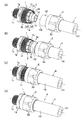
- the longitudinal cross-sectional view which shows the hose coupling which concerns on embodiment of this invention (a) shows the state before hose insertion, (b) shows the state after hose insertion, (c) is the time of a movement start of a fastener. (D) shows the state after the end of movement of the fastener. It is the same perspective view, (a) shows the state before hose insertion, (b) shows the state after hose insertion, (c) shows the state at the time of movement of a clamp, (d) shows the clamp It shows the state after the end of the movement of the tool. It is a vertical front view which shows the disassembled state of the hose coupling which concerns on embodiment of this invention. It is the same perspective view, (a) has shown the whole decomposition
- the nipple 1 into which the connecting end of the flexible hose H is inserted, and the axial reciprocation with respect to this nipple 1 A clamp 2 provided and an expansion / contraction sleeve 3 disposed on the outer peripheral surface of the nipple 1 via the connection end of the hose H, and after the connection end of the hose H is inserted into the outer peripheral surface of the nipple 1,
- the inner peripheral surface H1 of the connection end of the hose H is the nipple 1 by moving the clamp 2 in the axial direction, for example, the insertion direction of the hose H (hereinafter referred to as the hose insertion direction) to reduce the diameter of the expansion sleeve 3.
- the hose H is closely connected to the outer peripheral surface so as not to be pulled out.
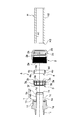
- the nipple 1 is formed in a cylindrical shape having an outer diameter substantially the same as or slightly larger than the inner diameter of the hose H, for example, with a hard material such as a metal such as brass or hard synthetic resin Can be formed into a cylindrical shape with a thin wall thickness by pressing or other forming a plate material made of a rigid material, and the diameter is gradually enlarged in the hose insertion direction on the outer peripheral surface of the plate from the largest diameter portion An annular bulging portion 1a is formed to be gradually reduced in diameter.
- a hard material such as a metal such as brass or hard synthetic resin
- the annular bulging portion 1a has an enlarged diameter surface 1a1 which gradually expands in diameter in the hose insertion direction from the tip edge 1b in a direction opposite to the hose insertion direction of the nipple 1 (hereinafter referred to as reverse insertion direction)
- the diameter reducing surface 1a2 gradually decreasing in diameter from the diameter portion in the hose insertion direction is continuously disposed, and in the example shown in FIGS. As an example, it is also possible to incline in a curved surface.
- a back side outer peripheral surface 1c having the same diameter as the minimum diameter portion of the reduced diameter surface 1a is formed in a predetermined length in the hose insertion direction on the rear side of the reduced diameter surface 1a2 of the bulging portion 1a in the hose insertion direction.
- a reverse tapered surface 1d gradually expanding in diameter toward the tip, and in the example shown in FIG. 1 (d), the nipple 1 is tightened by the fastener 2 described later.
- the hose H is pushed inward by the pressing cylinder 4 by projecting the pressing cylinder 4 which will be described later than the tip edge 1 b of the second embodiment so that the inner end portion thereof is continuous with the reverse tapered surface 1 d of the nipple 1. It is preferable to arrange.
- an annular step 1e that protrudes substantially perpendicularly from the back side outer peripheral surface 1c is integrally formed.
- a slide means 1f is formed to support the clamp 2 to be described later reciprocably in the hose insertion direction and in the direction opposite to the hose insertion direction.
- flat portions on which tools etc. engage are made circumferentially on the outer peripheral surface of the nipple 1 at appropriate intervals as in the example shown in FIGS. It is preferable to form a plurality of projections, or to form an uneven portion such as a knurled.
- the fastener 2 is formed of a material similar to or different from the nipple 1 and formed in a substantially cylindrical shape having an inner diameter larger than the outer diameter of the hose H, and engaged with the slide means 1f of the nipple 1 on the inner peripheral surface thereof.
- a slide means 2a is formed to support reciprocably in the hose insertion direction and the counter insertion direction.
- a screw is used to relatively reciprocate in the hose insertion direction and the counter insertion direction by rotating the clamp 2 relative to the nipple 1. It is preferable to form.
- the sleeve diameter reducing means it is preferable to directly form on the inner peripheral surface of the fastener 2 a pressing surface portion 2b which is inclined in a tapered shape in which the inner diameter gradually decreases in the counter-insertion direction.
- a pressing sleeve is rotatably provided on the inner side (inner periphery) of the fastener 2 and the inner circumferential surface of the pressing sleeve is opposed to the outer circumferential surface of the cylindrical expansion / contraction portion 3e of the expansion sleeve 3 described later. It is also possible to use a tapered pressing surface portion whose inner diameter gradually decreases in diameter toward the opposite insertion direction.
- Another pressing cylinder 4 is formed to face the enlarged diameter surface 1a1 of the bulging portion 1a as the clamp 2 moves in the axial direction.
- non-slip means 2d for rotational operation on the outer peripheral surface of the clamp 2 for example, as in the examples shown in FIGS. It is preferable to form a plurality of projections, or to form an uneven portion such as a knurled.
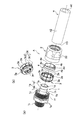
- the expansion / contraction sleeve 3 is formed in a substantially cylindrical shape, for example, of an elastically deformable material such as polyacetal resin or a synthetic resin excellent in slipperiness and heat resistance of the other surface, and inserted into the annular step 1e of the nipple 1 Thus, it is disposed to face the reduced diameter surface 1a2 of the nipple 1 and the back side outer peripheral surface 1c, and in particular, a portion on the opposite side of the hose insertion direction opposite to the reduced diameter surface 1a2 is used as the inlet 3a. Furthermore, as shown in FIGS.
- the expansion / contraction sleeve 3 undergoes a diameter expansion deformation at the time and before the insertion of the hose H, and at least the inner diameter of the inlet 3a It is set to be larger than the outer diameter of the hose H inserted along the reduced diameter surface 1a2 of 1a, and as shown in FIG. 1 (d), the pressing surface 2b is moved along with the axial movement of the fastener 2. When pressed, the diameter is reduced and the inner diameter of the inlet 3a is set to be smaller than the outer diameter of the hose H inserted along the reduced diameter surface 1a2 of the bulging portion 1a.
- the pressing cylinder 4 is separately or integrally provided on the inner peripheral surface of the fastener 2, the diameter-increased surface 1a1 of the bulging part 1a and the pressing cylinder 4 by axial movement of the fastener 2.
- the outer peripheral surface H2 of the hose H is inserted into the hose insertion direction side end surface (back end surface) 4a of the pressing cylinder 4 and the non-hose insertion of the expansion sleeve 3
- the outer peripheral surface H2 of the hose H which is bulgingly deformed toward the engagement recess 2c through the annular space S formed between the end surface (inlet side end surface) 3b and the engagement side Close contact and press along 2c.
- the expansion / contraction sleeve 3 is formed so as to gradually expand in diameter in the counter-insertion direction, and the axially extending slit 3c is cut out to be elastically deformable in the radial direction, and
- An annular convex portion is formed in the inlet portion 3a opposite to the outer peripheral surface H2 of the hose H, and the inner diameter of the annular convex portion is formed on the diameter-reduced surface 1a2 of the bulging portion 1a before and during insertion of the hose H.
- the diameter is set to be smaller than the outer diameter of the hose H inserted along the reduced diameter surface 1a2 of the portion 1a. That is, the inner diameter of the expansion sleeve 3 at the back in the hose insertion direction is set substantially the same as the outer diameter of the hose H inserted along the reduced diameter surface 1b2 of the bulging portion 1b, and the axial movement of the fastener 2 is achieved.
- the diameter of the expansion and contraction sleeve 3 is deformed and the inner peripheral surface 3d and the back outer periphery of the nipple 1 are reduced.
- the annular convex portion serving as the inlet 3 a thereof bites into the outer peripheral surface H 2 of the hose H and is further strongly sandwiched between the reduced diameter surface 1 a 2 of the nipple 1.
- the first embodiment can be used as the slide means 1f of the nipple 1
- the screw part is engraved, the inner screw part is cut as the slide means 2a of the clamp 2 opposed to this, the outer screw part 1f and the inner screw part 2a are screwed together, and the clamp 2 is fixed to the nipple 1
- the pressing surface portion 2b integrally formed on the inner peripheral surface of the fastener 2 presses the inlet portion 3a of the expansion and contraction sleeve 3 so as to reduce the diameter thereof.
- this expansion / contraction sleeve 3 is a cylinder having an annular convex portion to be the inlet portion 3a, an end face (inlet side end face) 3b opposite to the hose insertion direction and an inner circumferential surface 3d.
- a ring-shaped portion 3f formed integrally from the other end of the cylindrical portion 3e in the hose insertion direction toward the back side outer peripheral surface 1c of the nipple 1; While being used as an abutment surface of the tip end surface (cut surface) H3 of the hose H, a plurality of slits 3c are formed in the circumferential direction.
- one grit 3c1 is continued over the cylindrical expansion / contraction portion 3e and the annular collar portion 3f, but the other grit 3c2 is partial to the cylindrical expansion / contraction portion 3e or the annular collar portion 3f It is formed in.
- a stopper 3g opposed to the tip end edge 1h of the external thread to be the sliding means 1f of the nipple 1 is integrally protruded.
- the axial dimension from the stopper 3g to the annular flange 3f and the axial dimension from the tip end edge 1h of the external thread portion 1f of the nipple 1 to the annular step 1e are set in advance.
- the annular collar portion 3f of the expansion / contraction sleeve 3 is positioned to abut against the annular step 1e of the nipple 1
- the annular collar 3f is brought into contact with the annular step 1e of the nipple 1 only by looking at the positional relationship between the stopper 3g and the tip edge 1h of the external thread 1f, for example, the looseness between them. It can be determined whether or not it is correctly assembled.
- the hose H reaches the target position with the backlash between the stopper 3g and the tip edge 1h of the external thread 1f. It can be easily detected that the insertion has been made reliably, and the expansion and contraction sleeve 3 can be prevented from being deformed and broken with the insertion of the hose H.
- the separate ring to be the pressing cylinder portion 4 is formed by cutting the slit 4b extending along its entire axial length so as to be elastically deformable in the radial direction.
- the tapered surfaces 4d and 2e are formed on the outer peripheral surface 4c and / or the inner peripheral surface of the clamp 2 opposed thereto so as to press the separate ring 4 so as to reduce its diameter.
- the inner diameter in the state is set to be smaller than the outer diameter of the hose H inserted along the enlarged diameter surface 1a1 of the bulging portion 1a.
- connection portion 1i for connecting to a pipe connection port (not shown) of another device is continuously provided on the back side in the hose insertion direction with respect to the external screw portion formed as the slide means 1f of the nipple 1 .
- the connection portion 1i is formed with an outer thread corresponding thereto, and When an external screw is engraved on the outer peripheral surface of the pipe connection port, an internal screw corresponding to this is engraved.
- the nipple 1 is a cut product obtained by shaving a cylindrical material, for example, by cutting, and an external thread is cut as the connection portion 1i.
- the hose H is made of a soft material such as silicone rubber and a soft synthetic resin such as vinyl chloride, and it is preferable that the inner peripheral surface H1 and the outer peripheral surface H2 be flat.
- a specific example thereof is a laminated hose in which a plurality or a single synthetic resin blade (reinforcing yarn) is spirally embedded as an intermediate layer between the transparent or opaque outer layer and the inner layer, or an intermediate layer
- a braided reinforced hose in which a material is braided on the outer peripheral surface of a hose, a spiral reinforced hose in which a metal wire or a hard synthetic resin wire is embedded in a spiral shape, a flexible synthetic resin hose having a single layer structure, or the like is used.
- the hose H is inserted into a separate ring that becomes the clamp 2 and the pressing cylinder 4, and then the tip of the hose H is directed to the insertion space of the hose H and inserted along the bulging portion 1 a of the nipple 1 Start.
- the annular convex portion to be the inlet portion 3a of the expansion / contraction sleeve 3 is expanded and deformed so as to be larger than the outer diameter of the hose H inserted along the reduced diameter surface 1a2 of the expanded portion 1a. Therefore, the tip end of the hose H is smoothly inserted between the inner peripheral surface 3 d of the expansion / contraction sleeve 3 and the outer peripheral surface 1 c of the nipple 1 and the reduced diameter surface 1 a 2 without abutting the tip of the hose H As shown in FIG. 1 (b) and FIG.
- the hose H has a tip end surface H3 butting against the annular step 1e of the nipple 1 via the annular flange 3f of the expansion / contraction sleeve 3, further hose H Can not be inserted.
- the pressing surface portion 2b abuts against the cylindrical expansion / contraction portion 3e of the expansion sleeve 3 by the movement of the fastening tool 2 in the hose insertion direction.
- the diameter of the cylindrical expansion and contraction part 3e of the expansion and contraction sleeve 3 is reduced and deformed, and the hose H is sandwiched between the annular convex part to be the inlet part 3a and the reduced diameter surface 1a2 of the expansion part 1a.
- the annular convex portion to be the inlet 3a bites into the outer peripheral surface H2 of the hose H, and the other inner peripheral surface 3d is in pressure contact with the outer peripheral surface H2 of the hose H.
- the hose insertion direction side end face (rear side end face) 4a of the separate ring which becomes the pressing cylinder 4 and the outer hose H direction end face (inlet side end face) of the expansion sleeve 3 The outer peripheral surface H2 of the hose H which is bulgingly deformed toward the engaging recess 2c through the annular space S formed between 3b and the squeezed deformed H is in close contact and pressure contact along the engaging recess 2c.
- the hose H is soft and easily deformed like, for example, a silicone hose, the bite and expansion / contraction of the inner peripheral surface 4e of the separate ring which becomes the annular convex portion and the pressing cylinder 4 which becomes the inlet 3a.
- the outer peripheral surface H2 of the hose H expands by an amount corresponding to the compression, and the hose insertion direction side end face (back side end face) 4a of the ring and the non-hose insertion direction side of the expansion sleeve 3
- the hose H is firmly clamped in the axial direction and the radial direction because it is strongly sandwiched between the end face (inlet side end face) 3b, and the seal between the outer peripheral face of the nipple 1 and the hose H while stabilizing the pushing position of the hose tip. Sex and pull-out strength can be increased.
- the outer screw portion and the inner screw portion screwed with each other are formed as the slide means 1f, 2a for moving the clamp 2 in the axial direction with respect to the nipple 1, it is not limited thereto. As long as the fastener 2 can be moved in the axial direction with respect to the sleeve 3, a structure other than a screw may be used.
Abstract
Description
詳しくは、ニップルの外周面に沿ってホースが挿入され、その外側に設けられた締め付け具の軸方向移動により、ホースの内周面がニップルの外周面に密着されるホース継手に関する。 The present invention relates to a hose coupling used for piping connection of a soft and deformable hose such as silicone rubber.
More specifically, the present invention relates to a hose joint in which a hose is inserted along the outer peripheral surface of a nipple and the inner peripheral surface of the hose is in close contact with the outer peripheral surface of the nipple by axial movement of a fastener provided on the outer side.
その接続時には、先ずナットにバックリングを係合させた状態で、このバックリングをナットと共にホースの外周に挿入して後方に設定し、次にインサートスリーブをホースの端末に嵌入した後、このインサートスリーブを第2ジョイントに嵌合するとともに、ホース端末の外周に嵌合したフロントリングを第2ジョイントに嵌合させる。そして、ナットを第2ジョイントに対し螺合することで、バックリングがフロントリング側に引き寄せられて、インサートスリーブの環状凸部ないし、その両湾曲斜面に外嵌されているホースの外周がフロントリングないしバックリングで径方向にしっかりと挟持されると同時に、環状凸部によって径方向に膨出変形した部位がフロントリングないしバックリングにより軸方向に挟持されている。 Conventionally, in a hose joint of this type, a front connected between a nut connected to a second joint configured as a nipple and an inner peripheral surface of a female screw of the nut and an outer peripheral surface of a hose tip The inner side of the hose end in a state of being connected to the ring, the back ring interposed between the rear end inner peripheral surface of the nut and the outer peripheral surface of the hose spaced apart from the front ring by a predetermined distance, and the second joint There is an insert sleeve which is fitted into a circumferential surface and which holds an inner and outer peripheral surface on the end of the hose together with a front ring or a buckling (see, for example, Patent Document 1).
At the time of connection, first, with the nut engaged with the back ring, insert this back ring together with the nut on the outer periphery of the hose and set it back, and then insert the insert sleeve into the end of the hose, The sleeve is fitted to the second joint, and the front ring fitted to the outer periphery of the hose end is fitted to the second joint. Then, by screwing the nut to the second joint, the buckling is drawn to the front ring side, and the outer periphery of the hose externally fitted on the annular convex portion of the insert sleeve or the both curved slopes is the front ring In addition, at the same time as being firmly clamped in the radial direction by the buckling, a portion which is radially expanded and deformed by the annular convex portion is clamped in the axial direction by the front ring or the buckling.
また、インサートスリーブと第2ジョイントの嵌合によって、インサートスリーブの内周に形成される連通穴と第2ジョイントの連通穴との間には隙間ができてしまい、この隙間に流体が浸入して液溜りが発生するため、不衛生になり易く、さらにインサートスリーブの嵌合筒体外周がOリングを介して第2ジョイントの大径段付き嵌合穴に液密に嵌合しているため、インサートスリーブの連通穴と第2ジョイントの連通穴との隙間に浸入した流体は該Oリングとも接触(接液)するため、不衛生となり易く、用途が限定されるという問題もあった。
そこで、予めインサートスリーブと第2ジョイントを一体化しておき、このインサートスリーブの環状凸部に沿ってホースを挿入し、定位置で待機するフロントリングに該ホースの端部を嵌入することにより、ナットの螺合までの工程を短縮化することや、連通路途中の液溜りやOリングとの接液の問題に左右されず、流体の種類や用途を選べるようにすることなどが考えられる。
しかし、この場合には、フロントリングの内径がホースの外径と略同一径で形成されているため、ホースの押し込み操作のみで該ホース端部をフロントリング内に嵌入させることが難しく、ホースが定位置まで確実に押し込まれない状態でナットの螺合が行われるおそれがある。このようにホース端部がフロントリング内に嵌入されないままナットを螺合すると、確実な接続が行えず、結果的にインサートスリーブの外周面とホースとのシール性及び抜け強度が低下するという問題がある。 However, in such a conventional hose joint, the end of the hose is fitted into the insert sleeve before the front ring is fitted, and then the nut is screwed if the insert sleeve is not fitted to the second joint As a result, it takes time and effort to connect and is not easy to operate, and there is a problem that connection can not be performed in a short time.
Also, due to the fitting of the insert sleeve and the second joint, a gap is created between the communication hole formed on the inner periphery of the insert sleeve and the communication hole of the second joint, and fluid infiltrates into this gap. As a liquid pool occurs, it is easy to become unsanitary, and furthermore, the fitting cylinder outer periphery of the insert sleeve is fluid-tightly fitted to the large diameter stepped fitting hole of the second joint via the O ring, The fluid that has entered the gap between the communication hole of the insert sleeve and the communication hole of the second joint is also in contact with (is in contact with) the O-ring, which tends to be unsanitary, resulting in a problem that the application is limited.
Therefore, the insert sleeve and the second joint are integrated in advance, the hose is inserted along the annular convex portion of the insert sleeve, and the end portion of the hose is inserted into the front ring which stands by at the fixed position. It is conceivable to shorten the process up to the screwing of the fluid or to select the type and use of the fluid without being influenced by the liquid accumulation in the communication passage and the liquid contact with the O-ring.
However, in this case, since the inner diameter of the front ring is formed to be substantially the same diameter as the outer diameter of the hose, it is difficult to fit the end of the hose into the front ring only by pushing the hose. There is a possibility that the nut may be screwed in a state in which the nut is not firmly pushed into the fixed position. As described above, if the nut is screwed while the end of the hose is not fitted into the front ring, a reliable connection can not be made, and as a result, the sealability and removal strength between the outer peripheral surface of the insert sleeve and the hose are reduced. is there.
その結果、ホース接続の作業性が向上してホース接続作業を誰にでも簡単に短時間でしかも確実に行うことができる。
また、連通路の途中に隙間ができる従来のものに比べ、ニップルの内周面に沿って形成される連通路の途中に液溜りやOリングとの接液などが発生しないので、衛生的であり、流体の種類や用途を選ばず、自由度が高まって使用勝手がよい。 The present invention having the features described above sets the inner diameter of the inlet facing the diameter reducing surface of the expansion sleeve larger than the outer diameter of the hose inserted along the diameter reducing surface of the bulging portion when the hose is inserted. By doing this, the tip end of the hose can be smoothly inserted between the expansion and contraction sleeve and the reduced diameter surface without inserting into the inlet of the expansion and contraction sleeve and can be inserted to a fixed position. After that, when the clamp is pressed by the pressing surface along with the axial movement of the clamp, the inner diameter of the inlet of the expansion sleeve is set smaller than the outer diameter of the hose inserted along the reduced diameter surface of the bulge. As a result, the hose is sandwiched between the inlet of the expansion sleeve and the reduced diameter surface of the nipple, so the push-in position of the hose tip is stabilized to improve the sealing performance and removal strength between the outer peripheral surface of the nipple and the hose. it can.
As a result, the workability of the hose connection is improved, and the hose connection operation can be performed easily and in a short time and reliably for anyone.
In addition, compared with the conventional one having a gap in the middle of the communication passage, no liquid pool or liquid contact with the O-ring occurs in the middle of the communication passage formed along the inner circumferential surface of the nipple. Yes, regardless of the type and application of the fluid, the degree of freedom is increased and usability is good.
その結果、特にホースが例えばシリコーンホースのように柔らかく変形し易い場合であっても、ホースの変形がシール性や抜け強度の向上に利用されるため、ホース抜けを確実に防止することができる。 Further, a pressing cylindrical portion formed separately from or integrally with the inner peripheral surface of the clamp so as to face the enlarged diameter surface of the bulging portion along with the axial movement of the clamp is provided, The engagement concave portion is opposed to the annular space formed between the hose insertion direction side end surface of the pressing cylinder and the non-hose insertion direction side end surface of the expansion sleeve in a tightened state by axial movement of the tool. When formed, the hose is radially interposed between the enlarged diameter surface of the bulging portion and the pressing cylinder by axial movement of the fastener, and at the same time the outer peripheral surface of the hose is the pressing cylinder. The outer peripheral surface of the hose that has been bulgingly deformed toward the engagement recess through the annular space formed between the end face of the hose in the direction of insertion of the hose and the end face of the expansion sleeve in the direction of inserting the hose. Is in close contact and press-contact along the engagement recess. It is possible to reliably sandwich the scan in the axial and radial directions.
As a result, even if the hose is particularly soft and easily deformed like, for example, a silicone hose, the deformation of the hose is used to improve the sealing performance and the removal strength, so that the hose can be reliably prevented from dropping off.
その結果、確実な接続が行える。 In the case where an annular flange facing the tip end surface of the hose is formed at the end of the expansion sleeve in the hose insertion direction toward the back outer peripheral surface of the nipple, the back outer peripheral surface of the nipple is formed. By setting the expansion sleeve, the insertion space of the hose is formed between the outer peripheral surface on the back side and the inner peripheral surface of the expansion sleeve, and with the insertion of the hose, the tip end surface is the annular ridge of the expansion sleeve Since the hose H can not be inserted further, the hose can be reliably inserted into the fixed position.
As a result, reliable connection can be made.
膨出部1aの縮径面1a2よりもホース挿入方向奥側には、縮径面1aの最小径部分と同径の奥側外周面1cが、ホース挿入方向に所定長さ形成されている。 The annular bulging
A back side outer
さらに、ニップル1の外周面には、回転操作用の滑り止め手段1gとして、例えば図2及び図4に示される例のように、工具などが係合する平面部を周方向へ適宜間隔毎に複数形成したり、その他にローレットなどの凹凸部を形成することが好ましい。 Further, on the back side of the
Furthermore, as the non-slip means 1g for rotational operation, flat portions on which tools etc. engage are made circumferentially on the outer peripheral surface of the
これらニップル1のスライド手段1f及び締め付け具2のスライド手段2aとしては、ニップル1に対し締め付け具2を相対的に回転操作することでホース挿入方向及び反挿入方向へ相対的に往復動させるネジを形成することが好ましい。
また、その他の例として、ニップル1と締め付け具2を面接触させてホース挿入方向へ移動することにより、凹凸嵌合して両者が移動不能に係止されるようにすることも可能である。 The fastener 2 is formed of a material similar to or different from the
As the slide means 1 f of the
In addition, as another example, it is also possible to make concavo-convex fit so that both can be locked so as not to move by bringing the
このスリーブ縮径手段としては、締め付け具2の内周面に、反挿入方向へ向けて内径が徐々に小径となるテーパー状に傾斜する押圧面部2bを直接形成することが好ましい。
また、その他の例として、締め付け具2の内側(内周)に押圧スリーブを回転自在に設け、この押圧スリーブの内周面を、後述する拡縮スリーブ3の筒状拡縮部3eの外周面と対向して、反挿入方向へ向けて内径が徐々に小径となるテーパー状に傾斜する押圧面部とすることも可能である。 Further, on the inner side of the clamp 2, there is provided a means for radially compressing the diameter of the cylindrical expansion /
As the sleeve diameter reducing means, it is preferable to directly form on the inner peripheral surface of the
As another example, a pressing sleeve is rotatably provided on the inner side (inner periphery) of the fastener 2 and the inner circumferential surface of the pressing sleeve is opposed to the outer circumferential surface of the cylindrical expansion /
さらに、拡縮スリーブ3は、図1(a)~(c)に示されるようにホースHの挿入前の時点及び挿入時には拡径変形しており、その少なくとも入口部3aの内径を、膨出部1aの縮径面1a2に沿って挿入されるホースHの外径よりも大きくなるように設定し、また図1(d)に示されるように締め付け具2の軸方向移動に伴い押圧面部2bで押圧された時には縮径変形して、入口部3aの内径を、膨出部1aの縮径面1a2に沿って挿入されたホースHの外径よりも小さくなるように設定している。 The expansion /
Furthermore, as shown in FIGS. 1 (a) to 1 (c), the expansion /
その後、締め付け具2の軸方向移動に伴い押圧面部2bで押圧された時には図1(d)に示されるように、拡縮スリーブ3が縮径変形して、その入口部3aとニップル1の縮径面1a2との間にホースHが径方向へ挟み込まれる。 According to such a hose joint A, when the hose H is inserted, as shown in FIGS. 1 (a) and 1 (b), the distal end portion of the hose H does not abut against the
Thereafter, when the clamp 2 is pressed by the
つまり、拡縮スリーブ3のホース挿入方向奥側における内径を、膨出部1bの縮径面1b2に沿って挿入されるホースHの外径と略同じに設定して、締め付け具2の軸方向移動に伴い押圧面部2bで拡縮スリーブ3が押圧された時には、入口部3aとなる環状の凸部がホースHの外周面H2に食い込み、その他の内周面3dがホースHの外周面H2に圧接するようにしている。 More specifically, the expansion /
That is, the inner diameter of the
その後、締め付け具2の軸方向移動に伴い押圧面部2bで押圧された時には図1(d)に示されるように、拡縮スリーブ3が縮径変形して内周面3dとニップル1の奥側外周面1cとの間にホースHが挟み込まれると同時に、その入口部3aとなる環状の凸部がホースHの外周面H2に食い込んでニップル1の縮径面1a2との間に更に強く挟み込まれる。
以下、本発明の一実施例を図面に基づいて説明する。 According to such a hose joint A, as shown in FIGS. 1 (a) and 1 (b) when the hose H is inserted, the tip of the hose H with respect to the annular convex portion to be the
Thereafter, when the clamp 2 is pressed by the
Hereinafter, an embodiment of the present invention will be described based on the drawings.
これらすり割り3cのうち一本のすり割り3c1を筒状拡縮部3e及び環状鍔部3fに亘り連続させているが、他のすり割り3c2は筒状拡縮部3e又は環状鍔部3fに部分的に形成している。 As shown in FIGS. 4 (a) and 4 (b), this expansion /
Among the
ここで、このストッパー3gから環状鍔部3fまでの軸方向寸法と、ニップル1の外ネジ部1fの先端縁1hから環状段部1eまでの軸方向寸法とが一致するように予め設定しておけば、ストッパー3gを外ネジ部1fの先端縁1hに当接させることにより、ニップル1の環状段部1eに対して拡縮スリーブ3の環状鍔部3fが当接するように位置決めされるとともに、拡縮スリーブ3のセット時において、ストッパー3gと外ネジ部1fの先端縁1hとの位置関係、例えば両者のガタ付き具合を見るだけで、環状鍔部3fがニップル1の環状段部1eと当接するように正しく組み付けられているか否かを判断可能になる。
また、ホースHの先端面H3を拡縮スリーブ3の環状鍔部3fに突き当てながら挿入することにより、ストッパー3gと外ネジ部1fの先端縁1hとのガタ付き具合で、ホースHが目的位置まで確実に挿入されたことを簡単に感知することができるとともに、ホースHの挿入に伴い拡縮スリーブ3が変形して破損することを防止できる。 Further, on the outer peripheral surface of the cylindrical expanding and
Here, the axial dimension from the
Also, by inserting the tip end face H3 of the hose H while abutting against the
この押圧筒部4となる別体のリングは、図4(a)に示される例の場合、その軸方向全長に延びるすり割り4bを切欠形成して径方向へ弾性変形可能にし、該リングの外周面4c及びそれと対向する締め付け具2の内周面の両方又はいずれか一方には、別体のリング4が縮径するように押圧するテーパー面4d,2eを形成し、この縮径された状態における内径を、膨出部1aの拡径面1a1に沿って挿入されるホースHの外径よりも小さくなるように設定している。
また、その他の例として押圧筒部4を、すり割りが無いリング状に成形し、縮径変形させることなく、ホースHを膨出部1aの拡径面1a1に押圧させるようにすることも可能である。 And in this Example 1, since the clamp 2 rotates relatively with respect to the
In the case of the example shown in FIG. 4 (a), the separate ring to be the
Further, as another example, it is possible to form the
図示される例ではニップル1が、円筒材料を例えば切削加工などで削り出した切削品であり、接続部1iとして外ネジが刻設されている。 Further, a
In the illustrated example, the
その具体例としては、その透明又は不透明な外層と内層との間に中間層として、複数本か又は単数本の合成樹脂製ブレード(補強糸)が螺旋状に埋設される積層ホースや、中間層として合成樹脂製又は金属製の断面矩形などの帯状補強材と断面円形などの線状補強材を螺旋状に巻き付けて一体化した螺旋補強ホースや、例えばガラス繊維や難燃性繊維などの糸状補強材をホース外周面に編組した編組補強ホースや、金属製線材や硬質合成樹脂製線材を螺旋状に埋設した螺旋補強ホースや、単層構造の軟質合成樹脂製ホースなどが用いられる。 On the other hand, the hose H is made of a soft material such as silicone rubber and a soft synthetic resin such as vinyl chloride, and it is preferable that the inner peripheral surface H1 and the outer peripheral surface H2 be flat.
A specific example thereof is a laminated hose in which a plurality or a single synthetic resin blade (reinforcing yarn) is spirally embedded as an intermediate layer between the transparent or opaque outer layer and the inner layer, or an intermediate layer A spiral reinforced hose integrated by spirally winding a band-shaped reinforcing material such as a rectangular or rectangular cross-section made of synthetic resin or metal and a linear reinforcing material such as a circular cross-section, thread-like reinforcement such as glass fiber or flame retardant fiber A braided reinforced hose in which a material is braided on the outer peripheral surface of a hose, a spiral reinforced hose in which a metal wire or a hard synthetic resin wire is embedded in a spiral shape, a flexible synthetic resin hose having a single layer structure, or the like is used.
図3及び図4(a)(b)に示すホース継手Aの分解状態から、図1(a)及び図2(a)に示すように、先ず、ニップル1の環状段部1e及び奥側外周面1cに対して拡縮スリーブ3がニップル1の膨出部1aを乗り越えながらセットされると、これら奥側外周面1cと拡縮スリーブ3の内周面3bとの間にホースHの挿入空間が形成される。
また、ホースHを締め付け具2及び押圧筒部4となる別体のリングに挿通し、その後、このホースHの先端部をホースHの挿入空間へ向けニップル1の膨出部1aに沿って挿入開始する。 Next, a method of connecting the hoses H by the hose joint A will be described according to the order of steps, and the effects obtained thereby will also be described.
From the disassembled state of the hose joint A shown in FIGS. 3 and 4 (a) and (b), as shown in FIGS. 1 (a) and 2 (a), first, the
In addition, the hose H is inserted into a separate ring that becomes the clamp 2 and the
これに伴い、リングの内周面4eが、膨出部1aの拡径面1a1に沿って挿入されたホースHの外周面H2と強く接触するため、これら締め付け具2の内周面とリングの外周面4cとの間にズレが発生してテーパー面4d,2eによりリングが縮径変形する。
これにより、それ以降は締め付け具2の移動によりリングの内周面4eがホースHの外周面H2に対し更に強く圧接してホース挿入方向へ引き寄せるように力が発生するとともに、拡縮スリーブ3の反ホース挿入方向側端面(入口側端面)3bとの間隔が徐々に狭くなる。 Next, move the clamp 2 in the hose insertion direction, and screw the
Along with this, the inner
As a result, the movement of the fastener 2 causes the inner
そして、これと同時に、押圧筒部4となる別体のリングの内周面4eがホースHの外周面H2に食い込んで、膨出部1aの拡径面1a1と押圧筒部4との間にホースHが径方向へ挟み込まれる。 Furthermore, as shown in FIG. 1 (d) and FIG. 2 (d), the
Then, at the same time, the inner
特にホースHが例えばシリコーンホースのように柔らかく変形し易い場合には、このような入口部3aとなる環状の凸部や押圧筒部4となる別体のリングの内周面4eの食い込み及び拡縮スリーブ3の内周面3dの圧接により、その圧縮分だけホースHの外周面H2が膨出して、リングのホース挿入方向側端面(奥側端面)4aと、拡縮スリーブ3の反ホース挿入方向側端面(入口側端面)3bとの間に強く挟み込まれるため、ホースHが軸方向及び径方向へ確実に挟持され、ホース先端の押し込み位置を安定化しながらニップル1の外周面とホースHとのシール性及び抜け強度を高めることができる。 Thus, the hose insertion direction side end face (rear side end face) 4a of the separate ring which becomes the
In particular, when the hose H is soft and easily deformed like, for example, a silicone hose, the bite and expansion / contraction of the inner
1a1 拡径面 1a2 縮径面
1c 奥側外周面 2 締め付け具
2b 押圧面部 2c 係合凹部
3 拡縮スリーブ 3a 入口部
3b 反ホース挿入方向側端面(入口側端面)
3c すり割り 3d 内周面
3f 環状鍔部 4 押圧筒部
4a ホース挿入方向側端面(奥側端面)
H ホース H1 内周面
H2 外周面 H3 先端面 DESCRIPTION OF
H hose H1 inner circumferential surface H2 outer circumferential surface H3 tip surface
Claims (4)
- ニップルの外周面に沿ってホースが挿入され、その外側に設けられた締め付け具の軸方向移動により、前記ホースの内周面が前記ニップルの外周面に密着されるホース継手であって、
前記ニップルの外周面に形成され、ホース挿入方向へ徐々に拡径する拡径面及びその最大径部分から徐々に縮径する縮径面を有する環状の膨出部と、
前記膨出部の縮径面及び該縮径面よりもホース挿入方向奥側に位置する奥側外周面と対向して設けられる径方向へ弾性変形可能な拡縮スリーブと、
前記締め付け具の内側に前記拡縮スリーブの外周面と対向して形成され、前記ニップルに対する該締め付け具の軸方向移動に伴って前記拡縮スリーブが縮径するように押圧する押圧面部とを備え、
前記拡縮スリーブの前記縮径面と対向する入口部の内径を、前記ホースの挿入時には、前記膨出部の縮径面に沿って挿入される前記ホースの外径よりも大きくなるように設定し、また前記締め付け具の軸方向移動に伴い前記押圧面部で押圧された時には、前記膨出部の縮径面に沿って挿入される前記ホースの外径よりも小さくなるように設定したことを特徴とするホース継手。 A hose coupling in which a hose is inserted along an outer peripheral surface of a nipple, and an inner peripheral surface of the hose is brought into close contact with an outer peripheral surface of the nipple by axial movement of a fastener provided on the outer side thereof.
An annular bulging portion formed on the outer peripheral surface of the nipple and having an enlarged diameter surface which gradually expands in the hose insertion direction and a reduced diameter surface which is gradually reduced in diameter from the largest diameter portion thereof;
An expanding sleeve that can be elastically deformed in the radial direction, which is provided opposite to the reduced diameter surface of the bulging portion and the back side outer peripheral surface located on the rear side in the hose insertion direction with respect to the reduced diameter surface;
The clamp includes a pressing surface formed inside the clamp to face the outer peripheral surface of the expansion and contraction sleeve and pressing the expansion and contraction sleeve so as to decrease in diameter along with the axial movement of the clamp relative to the nipple.
The inner diameter of the inlet facing the diameter reducing surface of the expansion sleeve is set to be larger than the outer diameter of the hose inserted along the diameter reducing surface of the bulging portion when the hose is inserted. Also, when pressed by the pressing surface along with the axial movement of the fastener, the diameter of the hose is set to be smaller than the outer diameter of the hose inserted along the reduced diameter surface of the bulging portion. And hose fittings. - 前記拡縮スリーブをホース挿入方向と逆方向に向けて徐々に拡径するように形成して、その軸方向へ延びるすり割りを切欠形成して径方向へ弾性変形可能にするとともに、前記拡縮スリーブの入口部に、前記ホースの外周面と対向する環状の凸部を形成し、該環状の凸部の内径を、前記ホースの挿入時には前記膨出部の縮径面に沿って挿入される前記ホースの外径よりも大きくなるように設定し、また前記締め付け具の軸方向移動に伴い前記押圧面部で前記拡縮スリーブが押圧された時には、前記環状の凸部の内径を、前記膨出部の縮径面に沿って挿入される前記ホースの外径よりも小さくなるように設定したことを特徴とする請求項1記載のホース継手。 The expansion sleeve is formed so as to gradually increase in diameter in the direction opposite to the hose insertion direction, and a slot extending in the axial direction is cut out to make it elastically deformable in the radial direction, and The inlet portion is formed with an annular convex portion facing the outer peripheral surface of the hose, and the inner diameter of the annular convex portion is inserted along the diameter reducing surface of the bulging portion when the hose is inserted. When the expansion sleeve is pressed by the pressing surface as the clamp is moved in the axial direction, the inner diameter of the annular convex portion is determined by the contraction of the bulging portion. The hose coupling according to claim 1, characterized in that the diameter is smaller than the outer diameter of the hose inserted along the radial surface.
- 前記締め付け具の内周面に、該締め付け具の軸方向移動に伴って前記膨出部の拡径面と対向するように形成される押圧筒部を別体又は一体に設け、前記締め付け具の軸方向移動による締め付け状態で、該押圧筒部のホース挿入方向側端面と、前記拡縮スリーブの反ホース挿入方向側端面との間に形成される環状空間と対向するように係合凹部を形成したことを特徴とする請求項1又は2記載のホース継手。 On the inner peripheral surface of the clamp, a pressing cylinder portion formed separately or integrally is formed so as to face the enlarged diameter surface of the bulging part along with the axial movement of the clamp; An engagement recess is formed to face an annular space formed between the hose insertion direction side end surface of the pressing cylinder and the non-hose insertion direction side end surface of the expansion sleeve in a tightened state by axial movement. The hose coupling according to claim 1 or 2, characterized in that:
- 前記拡縮スリーブのホース挿入方向の端部に、前記ホースの先端面と対向する環状鍔部を、前記ニップルの奥側外周面に向けて形成したことを特徴とする請求項1、2又は3記載のホース継手。 The ring-shaped collar part which opposes the front end surface of the said hose was formed in the end part of the hose insertion direction of the said expansion / contraction sleeve toward the back side outer peripheral surface of the said nipple. Hose fittings.
Priority Applications (1)
| Application Number | Priority Date | Filing Date | Title |
|---|---|---|---|
| CN201080039029.0A CN102575801B (en) | 2009-09-02 | 2010-09-01 | Hose joint |
Applications Claiming Priority (2)
| Application Number | Priority Date | Filing Date | Title |
|---|---|---|---|
| JP2009202862A JP4868371B2 (en) | 2009-09-02 | 2009-09-02 | Hose fittings |
| JP2009-202862 | 2009-09-02 |
Publications (1)
| Publication Number | Publication Date |
|---|---|
| WO2011027766A1 true WO2011027766A1 (en) | 2011-03-10 |
Family
ID=43649301
Family Applications (1)
| Application Number | Title | Priority Date | Filing Date |
|---|---|---|---|
| PCT/JP2010/064887 WO2011027766A1 (en) | 2009-09-02 | 2010-09-01 | Hose joint |
Country Status (4)
| Country | Link |
|---|---|
| JP (1) | JP4868371B2 (en) |
| CN (1) | CN102575801B (en) |
| MY (1) | MY162527A (en) |
| WO (1) | WO2011027766A1 (en) |
Cited By (7)
| Publication number | Priority date | Publication date | Assignee | Title |
|---|---|---|---|---|
| EP2447586A1 (en) * | 2010-10-26 | 2012-05-02 | Michael Meier | Hose coupling |
| WO2015029815A1 (en) * | 2013-08-30 | 2015-03-05 | 株式会社トヨックス | Tube joint |
| JP2015048887A (en) * | 2013-08-30 | 2015-03-16 | 株式会社トヨックス | Pipe joint |
| JP2015048888A (en) * | 2013-08-30 | 2015-03-16 | 株式会社トヨックス | Pipe joint |
| JP2016020743A (en) * | 2015-08-27 | 2016-02-04 | 株式会社トヨックス | Pipe joint |
| US10006570B2 (en) | 2013-07-05 | 2018-06-26 | Junkosha Inc. | Pipe joint |
| JP2019002462A (en) * | 2017-06-14 | 2019-01-10 | 株式会社カネカ | Tube joint |
Families Citing this family (6)
| Publication number | Priority date | Publication date | Assignee | Title |
|---|---|---|---|---|
| JP2015052344A (en) * | 2013-09-06 | 2015-03-19 | 本田技研工業株式会社 | Hose attachment structure |
| US9657656B2 (en) * | 2014-08-27 | 2017-05-23 | Continental Automotive Systems, Inc. | Idle air control valve for use in a small engine and having a protective shroud with valve seat |
| CN106820530A (en) * | 2016-12-30 | 2017-06-13 | 重庆鹏旭新能源有限公司 | A kind of water heater integration formula shampoo trap |
| CN107504304A (en) * | 2017-09-01 | 2017-12-22 | 全球能源互联网研究院 | A kind of change current valve module FEP hose joint assemblies |
| EP3706598B1 (en) * | 2017-11-09 | 2022-01-05 | Oelschläger Metalltechnik GmbH | Telescopic column, more particularly for pieces of furniture, such as tables, and table with column of this kind |
| EP3956592B1 (en) * | 2019-04-18 | 2023-01-18 | Husqvarna Ab | Hose connector |
Citations (3)
| Publication number | Priority date | Publication date | Assignee | Title |
|---|---|---|---|---|
| JPH0727273A (en) * | 1993-06-28 | 1995-01-27 | Toyotsukusu:Kk | Hose joint |
| JP2001041380A (en) * | 1999-07-28 | 2001-02-13 | Nitta Moore Co | Tube coupling |
| JP3088531U (en) * | 2002-03-12 | 2002-09-20 | 株式会社リガルジョイント | Hose joint connection structure |
Family Cites Families (3)
| Publication number | Priority date | Publication date | Assignee | Title |
|---|---|---|---|---|
| US4900068A (en) * | 1988-12-19 | 1990-02-13 | Heyco Molded Products, Inc. | Liquid tight connector for flexible non-metallic conduit and flexible non-metallic tubing |
| JPH0431066Y2 (en) * | 1989-12-28 | 1992-07-27 | ||
| KR980008820U (en) * | 1996-07-10 | 1998-04-30 | 박강훈 | Synthetic hose connection |
-
2009
- 2009-09-02 JP JP2009202862A patent/JP4868371B2/en active Active
-
2010
- 2010-09-01 MY MYPI2012000900A patent/MY162527A/en unknown
- 2010-09-01 WO PCT/JP2010/064887 patent/WO2011027766A1/en active Application Filing
- 2010-09-01 CN CN201080039029.0A patent/CN102575801B/en not_active Expired - Fee Related
Patent Citations (3)
| Publication number | Priority date | Publication date | Assignee | Title |
|---|---|---|---|---|
| JPH0727273A (en) * | 1993-06-28 | 1995-01-27 | Toyotsukusu:Kk | Hose joint |
| JP2001041380A (en) * | 1999-07-28 | 2001-02-13 | Nitta Moore Co | Tube coupling |
| JP3088531U (en) * | 2002-03-12 | 2002-09-20 | 株式会社リガルジョイント | Hose joint connection structure |
Cited By (8)
| Publication number | Priority date | Publication date | Assignee | Title |
|---|---|---|---|---|
| EP2447586A1 (en) * | 2010-10-26 | 2012-05-02 | Michael Meier | Hose coupling |
| US10006570B2 (en) | 2013-07-05 | 2018-06-26 | Junkosha Inc. | Pipe joint |
| WO2015029815A1 (en) * | 2013-08-30 | 2015-03-05 | 株式会社トヨックス | Tube joint |
| JP2015048887A (en) * | 2013-08-30 | 2015-03-16 | 株式会社トヨックス | Pipe joint |
| JP2015048888A (en) * | 2013-08-30 | 2015-03-16 | 株式会社トヨックス | Pipe joint |
| CN105593592A (en) * | 2013-08-30 | 2016-05-18 | 东洋克斯株式会社 | Tube joint |
| JP2016020743A (en) * | 2015-08-27 | 2016-02-04 | 株式会社トヨックス | Pipe joint |
| JP2019002462A (en) * | 2017-06-14 | 2019-01-10 | 株式会社カネカ | Tube joint |
Also Published As
| Publication number | Publication date |
|---|---|
| CN102575801B (en) | 2014-07-23 |
| JP4868371B2 (en) | 2012-02-01 |
| MY162527A (en) | 2017-06-15 |
| CN102575801A (en) | 2012-07-11 |
| JP2011052772A (en) | 2011-03-17 |
Similar Documents
| Publication | Publication Date | Title |
|---|---|---|
| WO2011027766A1 (en) | Hose joint | |
| JP5311795B2 (en) | Pipe fitting | |
| JP4174738B2 (en) | Hose fittings | |
| WO2010064519A1 (en) | Resin pipe joint | |
| TWI534382B (en) | Resin pipe fittings | |
| WO2013115044A1 (en) | Pipe joint | |
| JP2008095765A (en) | Hose joint | |
| JP2008286260A (en) | Pipe joint | |
| JP2008286259A (en) | Pipe joint | |
| JP2006242348A (en) | Pipe joint | |
| JP2011069484A (en) | Hose joint | |
| WO2011058877A1 (en) | Hose connector | |
| JP2008138694A (en) | Pipe joint | |
| JP5268100B2 (en) | Pipe fitting | |
| JP3386406B2 (en) | Pipe fittings | |
| JP4751920B2 (en) | Resin pipe fitting | |
| JP4885201B2 (en) | Resin pipe fitting | |
| JP6294986B1 (en) | Fitting for straight pipe | |
| JP5112216B2 (en) | Resin pipe fitting | |
| JP5098101B2 (en) | Pipe fitting | |
| JP2013029193A (en) | Pipe coupling | |
| US9518689B2 (en) | Two piece male hose coupler and method for securing a garden hose to a coupler | |
| JP2017201195A (en) | Hose joint metal fitting | |
| JP5934667B2 (en) | Pipe fitting | |
| JP5690553B2 (en) | Resin pipe joint assembly structure and resin pipe joint assembly method |
Legal Events
| Date | Code | Title | Description |
|---|---|---|---|
| WWE | Wipo information: entry into national phase |
Ref document number: 201080039029.0 Country of ref document: CN |
|
| 121 | Ep: the epo has been informed by wipo that ep was designated in this application |
Ref document number: 10813715 Country of ref document: EP Kind code of ref document: A1 |
|
| NENP | Non-entry into the national phase |
Ref country code: DE |
|
| WWE | Wipo information: entry into national phase |
Ref document number: 1201000923 Country of ref document: TH |
|
| WWE | Wipo information: entry into national phase |
Ref document number: 794/KOLNP/2012 Country of ref document: IN |
|
| 122 | Ep: pct application non-entry in european phase |
Ref document number: 10813715 Country of ref document: EP Kind code of ref document: A1 |