WO2011027709A1 - 空気調和機の室外機 - Google Patents
空気調和機の室外機 Download PDFInfo
- Publication number
- WO2011027709A1 WO2011027709A1 PCT/JP2010/064493 JP2010064493W WO2011027709A1 WO 2011027709 A1 WO2011027709 A1 WO 2011027709A1 JP 2010064493 W JP2010064493 W JP 2010064493W WO 2011027709 A1 WO2011027709 A1 WO 2011027709A1
- Authority
- WO
- WIPO (PCT)
- Prior art keywords
- outdoor unit
- unit base
- defrost heater
- bracket
- air conditioner
- Prior art date
- Legal status (The legal status is an assumption and is not a legal conclusion. Google has not performed a legal analysis and makes no representation as to the accuracy of the status listed.)
- Ceased
Links
Images




Classifications
-
- F—MECHANICAL ENGINEERING; LIGHTING; HEATING; WEAPONS; BLASTING
- F28—HEAT EXCHANGE IN GENERAL
- F28F—DETAILS OF HEAT-EXCHANGE AND HEAT-TRANSFER APPARATUS, OF GENERAL APPLICATION
- F28F17/00—Removing ice or water from heat-exchange apparatus
-
- F—MECHANICAL ENGINEERING; LIGHTING; HEATING; WEAPONS; BLASTING
- F24—HEATING; RANGES; VENTILATING
- F24F—AIR-CONDITIONING; AIR-HUMIDIFICATION; VENTILATION; USE OF AIR CURRENTS FOR SCREENING
- F24F1/00—Room units for air-conditioning, e.g. separate or self-contained units or units receiving primary air from a central station
- F24F1/06—Separate outdoor units, e.g. outdoor unit to be linked to a separate room comprising a compressor and a heat exchanger
-
- F—MECHANICAL ENGINEERING; LIGHTING; HEATING; WEAPONS; BLASTING
- F24—HEATING; RANGES; VENTILATING
- F24F—AIR-CONDITIONING; AIR-HUMIDIFICATION; VENTILATION; USE OF AIR CURRENTS FOR SCREENING
- F24F1/00—Room units for air-conditioning, e.g. separate or self-contained units or units receiving primary air from a central station
- F24F1/06—Separate outdoor units, e.g. outdoor unit to be linked to a separate room comprising a compressor and a heat exchanger
- F24F1/36—Drip trays for outdoor units
-
- F—MECHANICAL ENGINEERING; LIGHTING; HEATING; WEAPONS; BLASTING
- F24—HEATING; RANGES; VENTILATING
- F24F—AIR-CONDITIONING; AIR-HUMIDIFICATION; VENTILATION; USE OF AIR CURRENTS FOR SCREENING
- F24F13/00—Details common to, or for air-conditioning, air-humidification, ventilation or use of air currents for screening
-
- F—MECHANICAL ENGINEERING; LIGHTING; HEATING; WEAPONS; BLASTING
- F25—REFRIGERATION OR COOLING; COMBINED HEATING AND REFRIGERATION SYSTEMS; HEAT PUMP SYSTEMS; MANUFACTURE OR STORAGE OF ICE; LIQUEFACTION SOLIDIFICATION OF GASES
- F25B—REFRIGERATION MACHINES, PLANTS OR SYSTEMS; COMBINED HEATING AND REFRIGERATION SYSTEMS; HEAT PUMP SYSTEMS
- F25B30/00—Heat pumps
-
- F—MECHANICAL ENGINEERING; LIGHTING; HEATING; WEAPONS; BLASTING
- F24—HEATING; RANGES; VENTILATING
- F24F—AIR-CONDITIONING; AIR-HUMIDIFICATION; VENTILATION; USE OF AIR CURRENTS FOR SCREENING
- F24F11/00—Control or safety arrangements
- F24F11/30—Control or safety arrangements for purposes related to the operation of the system, e.g. for safety or monitoring
- F24F11/41—Defrosting; Preventing freezing
- F24F11/42—Defrosting; Preventing freezing of outdoor units
-
- F—MECHANICAL ENGINEERING; LIGHTING; HEATING; WEAPONS; BLASTING
- F24—HEATING; RANGES; VENTILATING
- F24F—AIR-CONDITIONING; AIR-HUMIDIFICATION; VENTILATION; USE OF AIR CURRENTS FOR SCREENING
- F24F13/00—Details common to, or for air-conditioning, air-humidification, ventilation or use of air currents for screening
- F24F13/22—Means for preventing condensation or evacuating condensate
- F24F13/222—Means for preventing condensation or evacuating condensate for evacuating condensate
Definitions
- the present invention relates to an outdoor unit of an air conditioner in which a defrost heater for preventing freezing of drain water is laid on an outdoor unit base.
- frost may be formed on the outdoor heat exchanger that functions as an evaporator during heating operation. Since heat exchange is hindered by this frost, when frost formation is detected, a defrost operation for removing the frost is performed. When the defrost operation is performed, the frost that has been frosted on the outdoor heat exchanger is melted and drained on the base of the outdoor unit, and then discharged to the outside through the drain discharge hole. However, in cold districts, it is easy to form frost, and the drain water dripped on the outdoor unit base may be re-frozen on the base before being discharged from the drain discharge hole at low outside air temperature. .
- a defrost heater seeds heater
- the defrost heater is energized to heat the outdoor unit base. This prevents drain water from refreezing on the outdoor unit base and prevents the outdoor fan from being locked due to the accumulation of ice.
- This defrost heater is usually equipped with a thermostat for preventing excessive temperature rise, and is configured to detect the surface temperature and to control on / off of energization to the defrost heater to keep the surface temperature within a certain range. Has been.
- a tubular heater laid on an outdoor unit base has a rectangular shape as a whole, a long concave portion is formed in the longitudinal direction of both ends, and two in the center of both longitudinal end portions.
- a screw hole is provided, and the bottom plate of the outdoor unit base is fixed by an isolation plate in which a socket is formed in the center portion surrounded by the screw hole and the long recess.
- the convex part is provided in several places in an elongate recessed part, and the contact part of an isolation plate and a heater is decreased by hold
- Japanese Utility Model Publication No. 4-10496 (see FIGS. 3 to 4) Japanese Patent No. 3882910 (see FIGS. 1 to 3)
- Patent Document 2 when the tubular defrost heater is pressed and fixed with an isolation plate (bracket) having a long recess, the dimensional tolerances of the rigid outdoor unit base and the defrost heater are mutually It is difficult to hold down and fix the defrost heater with a constant force, and the presser is swollen and displaced due to collision or vibration when transporting the outdoor unit, causing problems such as poor heating or contact with other parts There have been problems such as occurrence of damage and damage to the defrost heater due to excessive pressing.
- the isolation plate (bracket) itself is screwed directly to the bottom of the outdoor unit base and a drain hole is provided in the socket, the drain water dripped from the outdoor heat exchanger is blocked by the isolation plate, There is a risk of staying on the outdoor unit base until it reaches the hole, and the tip of the screw that secures the isolation plate protrudes from the back of the outdoor unit base. When hung, there was a problem that there was a risk of injury at the tip of the screw.
- the present invention has been made in view of such circumstances, and a defrost heater laid on an outdoor unit base can absorb a dimensional tolerance and can be securely fixed to a predetermined position with a constant force. It aims at providing the outdoor unit of the air conditioner which can achieve a freeze prevention function.
- the outdoor unit of an air conditioner of the present invention employs the following means. That is, in the outdoor unit for an air conditioner according to an aspect of the present invention, a defrost heater for preventing freezing of drain water is laid on the outdoor unit base, and the defrost heater is attached to the bottom surface of the outdoor unit base via a bracket.
- the bracket In the outdoor unit of the air conditioner that is fixed, the bracket includes an arm-shaped pressing portion having a free end on one end side for pressing the defrost heater, and the pressing portion includes the outdoor unit base and the defrost heater. It is configured to be able to bend so as to absorb dimensional tolerances and hold down the defrost heater.
- the bracket for fixing the defrost heater to the outdoor unit base includes the arm-shaped pressing portion having a free end at one end side for pressing the defrost heater, and the pressing portion has a dimensional tolerance of the outdoor unit base and the defrost heater.
- Bending function (bending function) of the holding part in which the dimensional tolerance of the outdoor unit base and the defrost heater which are rigid with respect to each other is arm-shaped because the defrost heater can be pressed by absorbing the The defrost heater can be pressed and fixed to the bottom surface of the outdoor unit base with a constant force. Therefore, it is possible to reliably fix the defrost heater at a predetermined position in spite of a collision or vibration during transportation of the outdoor unit, and achieve an intended freeze prevention function.
- the pressing portion may be configured such that a contact surface in contact with the defrost heater has a convex arc cross-sectional shape.
- the contact surface in contact with the defrost heater in the pressing portion has a convex arc cross-sectional shape
- the contact surface having the convex arc cross-section in the pressing portion is brought into contact with the outer peripheral surface of the defrost heater.
- the defrost heater can be fixed to the bottom surface of the outdoor unit base. Therefore, the defrost heater can be fixed so as not to damage the outline of the defrost heater due to burrs or the like at the edge portion of the pressing portion.
- the outdoor unit base can be efficiently heated while minimizing the contact area between the bracket and the defrost heater and suppressing the amount of heat transfer to the bracket side.
- the pressing portion is provided with a U-shaped punching portion on the end side of the bracket, whereby the remaining central portion is the pressing portion in the form of an arm,
- the structure by which the both side part is made into the fixed part to the said outdoor unit base of the said bracket may be sufficient.
- the pressing portion is provided with a U-shaped punched portion on the end side of the bracket, so that the remaining central portion is an arm-shaped pressing portion, and both side portions thereof are the outdoor unit bases of the bracket. Therefore, an arm-shaped pressing portion can be formed by punching out at the central portion of the fixing portion fixed to the outdoor unit base of the bracket. Therefore, by fixing the fixing portions on both sides to the outdoor unit base, the defrost heater can be firmly pressed against the outdoor unit base at the central pressing portion.
- the bracket is fixedly installed on the outdoor unit base in a state where a gap is secured between the bottom surface of the drain drainage channel provided on the bottom surface of the outdoor unit base. It may be configured.
- the bracket since the bracket is fixedly installed on the outdoor unit base in a state where a gap is secured between the bracket and the bottom surface of the drain drainage channel provided on the bottom surface of the outdoor unit base, the bracket flows through the drain drainage channel.
- the drain water flow is not obstructed by the bracket that fixes the defrost heater. Therefore, the drain water generated by the defrost operation can be quickly guided to the drain discharge hole and discharged to the outside. It can be surely prevented from staying on the machine base and refreezing.
- the bracket is configured to be screwed and fixed to a throttle portion that is raised upward by a predetermined height on the bottom surface of the outdoor unit base. Also good.
- the bracket since the bracket is fixed to the throttle portion that is raised upward by a predetermined height on the bottom surface of the outdoor unit base, the screw for fixing the bracket to the outdoor unit base is fixed. Since the tip of this is located in the upward convex throttle portion provided for increasing the rigidity of the outdoor unit base, it does not protrude from the lower surface of the outdoor unit base. Therefore, when the outdoor unit is installed, there is no risk of injury from the tip of the screw even if an operator places a hand on the outdoor unit base, and safety can be ensured.
- the bracket is provided with a pair of pressing portions at both ends, and holds the defrost heater that is bent and laid on the outdoor unit base at two locations. It may be configured to be.
- the bracket is configured so that a pair of pressing portions are provided at both ends, and the defrost heater that is bent and formed on the outdoor unit base is pressed at two locations.
- a defrost heater bent so as to reciprocate can be pressed and fixed to the outdoor unit base at two locations.
- the bracket includes a locking portion that is locked to a notch portion provided on the bottom surface of the outdoor unit base at the other end. Also good.
- the bracket since the bracket includes the locking portion locked to the notch portion provided on the bottom surface of the outdoor unit base at the other end, the locking provided at the other end of the bracket.
- the bracket can be fixed with one screw stop by locking the part to the notch provided on the bottom surface of the outdoor unit base and fixing one end of the bracket to the outdoor unit base throttle part. . Therefore, the fixing operation of the defrost heater can be simplified and the assemblability can be improved.
- the dimensional tolerances of the rigid outdoor unit base and the defrost heater are absorbed by the bending function of the holding portion having an arm shape, and the defrost heater is pressed and fixed to the bottom surface of the outdoor unit base with a constant force. Therefore, the defrost heater can be securely fixed at a predetermined position regardless of a collision or vibration during transportation of the outdoor unit, and an intended anti-freezing function can be achieved.
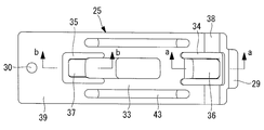
- FIG. 6B is a sectional view taken along line aa in FIG. 6A.
- FIG. 6B is a sectional view taken along line bb in FIG. 6A.
- FIG. 6C is a sectional view taken along line cc in FIG. 6B.
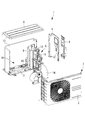
- FIG. 1 shows an exploded perspective view of an outdoor unit of an air conditioner to which the present invention is applied
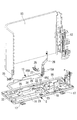
- FIG. 2 shows an exploded perspective view of its main part
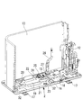
- FIG. 3 shows a defrost heater.
- An outdoor unit 1 of an air conditioner includes a laterally long rectangular casing 7 including an outdoor unit base 2, a front and left side panel 3, a right side panel 4, a service cover 5, a top panel 6, and the like. ing.
- the inside of the housing 7 is partitioned into a machine chamber 9 side and a heat exchanger chamber 10 side by a partition plate 8, and in addition to the compressor 11, piping 12, a four-way switching valve, an expansion are provided on the machine chamber 9 side.
- a valve, a control box, and the like are disposed, and an outdoor heat exchanger 13, an outdoor fan 14, an antifreezing defrost heater 15 for the outdoor unit base 2, and the like are provided on the heat exchanger chamber 10 side.
- the compressor 11, the outdoor heat exchanger 13, the outdoor fan 14, and the defrost heater 15 are installed on the outdoor unit base 2.
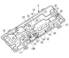
- the outdoor unit base 2 is a rectangular press-molded product having a dish shape with an upward rising wall 16 around the periphery, and mounting legs 17 are integrally formed on the back surfaces near both the left and right sides. It is welded to.
- These installation seats 18, 19, 20 are formed in a convex shape upward by a predetermined height from the bottom surface of the outdoor unit base 2.
- the bottom of the outdoor unit base 2 is slightly lowered from the bottom of the base so as to be along the front side (the back side in FIG. 4) and the back side (the front side in FIG. 4) of the region on the heat exchanger chamber 10 side.
- the drainage channels 21 and 22 are provided for collecting drain water on the bottom surface of the outdoor unit base 2 and discharging it to the outside. Drain discharge holes 23 and 24 are formed at the locations.
- the drainage channel 22 provided in the bottom face of the outdoor unit base 2 As shown in FIGS. 3 and 4, it is along the lower part of the outdoor heat exchanger 13 bent and formed in an L shape.
- a defrost heater 15 is laid.
- the defrost heater 15 is formed by bending a rod-shaped sheathed heater, and both end portions 15A are raised upward.
- an intermediate horizontal portion 15B connected to the both end portions 15A is laid by being bent along the drainage channel 22, and is fixed to the bottom surface of the outdoor unit base 2 at two locations via brackets 25. .
- a power supply harness 26 is connected to the defrost heater 15, and the surface temperature of the harness is detected, and the defrost heater 15 is turned off at a set temperature (for example, 35 ° C.) or higher to set the set temperature (for example, 25 A thermostat 27 for preventing the excessive temperature rise is provided to turn on the defrost heater 15 at a temperature below [° C.]. As shown in FIGS. 2 to 4, the thermostat 27 is bent up from a horizontal portion 15B laid on the outdoor unit base 2 of the defrost heater 15 and rises upward (FIG. 2). In the vicinity of the bending radius stop (see Fig. 6), the rising portion 15C is sandwiched and clipped.
- the bracket 25 is a rectangular sheet metal press-molded product laid so as to straddle the concave drainage channel 22, and is outdoors at one end (the right end in FIG. 6A).
- a locking portion 29 that is inserted and locked into a notch (insertion hole) 28 (see FIG. 2) provided at a position along the rear side (back side in FIG. 2) of the machine base 2 is provided.
- Screw fixing holes 30 are provided on the end side (left end side in FIG. 6A).
- the bottom surface of the outdoor unit base 2 to which the bracket 25 is screwed via a screw 31 is a throttle portion 32 for increasing rigidity that is raised upward by a predetermined height, as shown in FIG.
- the tip of the screw 31 is configured not to protrude from the back surface (lower surface) of the outdoor unit base 2.
- the intermediate portion 33 is between the bottom surface of the drainage channel 22 as shown in FIG. 6B.
- U-shaped punched portions 34 and 35 are provided in the vicinity of both ends of the bracket 25, respectively.
- the punched portions 34 and 35 are provided with arm-shaped pressing portions 36 and 37 for pressing the outer periphery of the defrost heater 15 at the remaining central portion, and both side portions thereof are fixed portions 38 and 39 for fixing the bracket 25 to the outdoor unit base 2. It is said that.
- the arc-shaped pressing portions 40 and 41 along the outer periphery of the defrost heater 15 are provided at the free ends of the arm-shaped pressing portions 36 and 37 as shown in FIGS. 6C and 6D.
- the contact surface 42 that contacts the outer periphery of the defrost heater 15 of the arc pressing portions 40 and 41 has an arc cross-sectional shape that is convex toward the contact surface 42 side.
- the intermediate portion 33 of the bracket 25 is provided with reinforcing ribs 43 on both sides and the center in the longitudinal direction.
- the outdoor heat exchanger 13 functions as an evaporator and absorbs heat from low-temperature outside air. For this reason, frost may be generated on the surface of the outdoor heat exchanger 13 depending on outside air conditions. Since this frost hinders heat exchange between the refrigerant and the outside air, when frost formation is detected, the heating cycle of the air conditioner is switched to the defrost cycle, and high-temperature refrigerant gas is supplied to the outdoor heat exchanger 13. Defrost operation.
- the drain water flows down the outdoor unit base 2 through the outdoor heat exchanger 13 and is collected into drain drain holes 23 and 24 through the drain channels 21 and 22. Discharged to the outside. During this time, the drain water is laid on the outdoor unit base 2 at an appropriate timing under defrost conditions so that the drain water does not freeze again on the outdoor unit base 2 and accumulates to lock the outdoor fan 14 or the like. By energizing the defrost heater 15, the outdoor unit base 2 is heated to prevent refreezing of the drain water.
- the defrost heater 15 detects the surface temperature so that the temperature does not rise excessively due to the defrost heater 15 being blown, etc., and the defrost heater is at a set temperature (for example, 35 ° C.) or higher. 15 is provided, and a thermostat 27 for preventing an excessive temperature rise is provided to turn on the defrost heater 15 at a set temperature (for example, 25 ° C.) or less. By controlling the surface temperature of the defrost heater 15 within a certain range, Temperature rise is prevented and peripheral equipment is protected.
- the defrost heater 15 absorbs the dimensional tolerances of the outdoor unit base 2 and the defrost heater 15 which are rigid to each other so as not to be displaced due to a collision or vibration during the transportation of the outdoor unit 1, and the defrost heater 15 with a constant force. It is necessary to press 15 and fix it firmly.
- the bracket 25 for fixing the defrost heater 15 is provided with arm-shaped pressing portions 36 and 37 each having a free end on one end side for pressing the defrost heater.
- the pressing portions 36 and 37 are connected to the outdoor unit base 2 and It is configured to be able to bend so that the dimensional tolerance of the defrost heater 15 can be absorbed and the defrost heater 15 can be pressed.
- the dimensional tolerance between the rigid outdoor unit base 2 and the defrost heater 15 is absorbed by the bending function (bending function) of the holding portions 36 and 37 having the arm shape, and the defrost heater 15 is fixed with a constant force. It can be pressed against the bottom surface of the base 2 and fixed. Accordingly, the defrost heater 15 is not displaced in spite of a collision or vibration during the transportation of the outdoor unit, and the defrost heater 15 is damaged due to defective heating or contact with other parts, or excessive pressing. Etc., the defrost heater 15 can be securely fixed at a predetermined position, and the intended freezing prevention function can be achieved.
- the contact surface 42 that contacts the defrost heater 15 of the arc pressing portions 40 and 41 in the pressing portions 36 and 37 is formed into a convex arc sectional shape on the contact surface 42 side, and the convex arc cross section of the pressing portions 36 and 37 is formed. Since the defrost heater 15 is fixed to the bottom surface of the outdoor unit base 2 by bringing the contact surface 42 in contact with the outer peripheral surface of the defrost heater 15, the defrost heater is caused by burrs or the like at the edge portions of the holding portions 36 and 37.
- the defrost heater 15 can be fixed so as not to damage the outer shell 15, the contact area between the bracket 25 and the defrost heater 15 is minimized, and the amount of heat transferred to the bracket 25 side is suppressed while the outdoor unit base 2 is Heating can be done efficiently.
- the pressing portions 36 and 37 are provided with U-shaped punched portions 34 and 35 on the end side of the bracket 25, so that the remaining central portions are arm-shaped pressing portions 36 and 37, and both side portions thereof. Is a fixed portion of the bracket 25 to the outdoor unit base 2.
- the arm-shaped pressing portions 36 and 37 can be formed by punching in the central portion of the fixing portions 38 and 39 fixed to the outdoor unit base 2 of the bracket 25. Accordingly, the fixing portions 38 and 39 on both sides are formed.
- the defrost heater 15 can be firmly pressed against the outdoor unit base 2 by the pressing portions 36 and 37 at the center.
- the bracket 25 is rigid with the notch portion (insertion hole) 28 of the outdoor unit base 2 in a state where a clearance is secured between the bracket 25 and the bottom surface of the drain drainage channel 22 provided on the bottom surface of the outdoor unit base 2. Therefore, the flow of the drain water flowing through the drain drainage channel 22 is not hindered by the bracket 25 that fixes the defrost heater 15, and therefore, the defrost operation is performed.
- the generated drain water can be promptly guided to the drain discharge holes 23 and 24 and discharged to the outside, and the drain water can be reliably prevented from staying on the outdoor unit base 2 and refreezing.
- the bracket 25 is fixed to the bottom surface of the outdoor unit base 2 with a screw 31 via a screw 31 on a rigidity increasing throttle portion 32 that is raised upward by a predetermined height.
- the tip of the screw 31 that fixes the bracket 25 to the outdoor unit base 2 is in the upwardly protruding throttle portion 32 provided for increasing the rigidity of the outdoor unit base 2. Since it is located, it does not protrude downward from the lower surface of the outdoor unit base 2. Therefore, when the outdoor unit 1 is installed, there is no risk of injury from the tip of the screw 31 even if an operator puts a hand on the outdoor unit base 2, and safety can be ensured.
- the bracket 25 is provided with a pair of holding portions 36 and 37 in the vicinity of both ends, and the defrost heater 15 that is bent and formed on the outdoor unit base 2 is installed.
- the defrost heater 15 that is bent so as to be reciprocated by one bracket 25 that is configured to be pressed at two locations and provided with a pair of pressing portions 36 and 37 at both ends is provided at the outdoor unit at two locations. It can be pressed against the base 2 and fixed. For this reason, the number of brackets 25 can be halved with respect to the necessary fixing portion of the defrost heater 15, and the configuration can be simplified and the cost can be reduced.
- the bracket 25 is provided with a locking portion 29 that is inserted and locked into a notch (insertion hole) 28 provided on the bottom surface of the outdoor unit base 2 on the other end side.
- the locking portion 29 provided at the other end is locked to the notch portion 28 provided on the bottom surface of the outdoor unit base 2, and one end of the bracket 25 is connected to the throttle portion 32 of the outdoor unit base 2 via screws 31.
- the bracket 25 can be fixed with one screw stop. Therefore, the fixing operation of the defrost heater 15 can be simplified and the assemblability can be improved.
- the bracket 25 is not particularly limited with respect to the constituent material, but can be made of a steel plate having a thickness of about 1 mm.
- the arm lengths of the holding portions 36 and 37 are designed to have a proper bending function.
Landscapes
- Engineering & Computer Science (AREA)
- Mechanical Engineering (AREA)
- General Engineering & Computer Science (AREA)
- Chemical & Material Sciences (AREA)
- Combustion & Propulsion (AREA)
- Physics & Mathematics (AREA)
- Thermal Sciences (AREA)
- Other Air-Conditioning Systems (AREA)
Abstract
室外機ベース上に敷設されるデフロストヒータを、寸法公差を吸収し一定の力で所定位置に確実に固定でき、所期の凍結防止機能を達成できる空気調和機の室外機を提供する。室外機ベース(2)上にドレン水の凍結を防止するデフロストヒータ(15)が敷設され、該デフロストヒータ(15)がブラケット(25)を介して室外機ベース(2)の底面に固定されている空気調和機の室外機において、ブラケット(25)は、デフロストヒータ(15)を押さえる一端側が自由端とされたアーム形状の押さえ部分を備え、該押さえ部分は、室外機ベース(2)およびデフロストヒータ(15)の寸法公差を吸収してデフロストヒータ(15)を押さえられるようにベンディング可能な構成とされている。
Description
本発明は、室外機ベース上にドレン水の凍結を防止するデフロストヒータが敷設されている空気調和機の室外機に関する。
ヒートポンプ式の空気調和機では、暖房運転時、蒸発器として機能する室外熱交換器に着霜(フロスト)することがある。この霜によって熱交換が阻害されるため、着霜が検知された場合、霜を取り除くデフロスト運転を行うようにしている。デフロスト運転を実施すると、室外熱交換器に着霜していた霜が融け、ドレン水となって室外機のベース上に滴下した後、ドレン排出穴を経て外部へと排出される。しかるに、寒冷地においては、着霜し易い上に、低外気温下では室外機ベース上に滴下したドレン水が、ドレン排出穴から排出される前にベース上で再凍結してしまう場合がある。
そこで、寒冷地向けの空気調和機では、室外機ベース上にデフロストヒータ(シーズヒータ)を敷設し、ドレン水が凍結するおそれがある場合、デフロストヒータに通電して室外機ベースを加温することによりドレン水の室外機ベース上での再凍結を防止し、氷が堆積することにより発生する室外ファンのロック等を防ぐようにしている。このデフロストヒータには、通常、過昇温防止用のサーモスタットが取付けられており、その表面温度を検知してデフロストヒータへの通電をオンオフ制御し、表面温度を一定範囲内に保持するように構成されている。
上記の如く、室外機ベース上にドレン水の凍結を防止するシーズヒータ等の管状ヒータを敷設した空気調和機の室外機として、例えば特許文献1,2に示されるようなものが知られている。特許文献2には、室外機ベース上に敷設されている管状ヒータを、全体が矩形形状で、両端の長手方向に長形の凹部が形成されるとともに、長手方向の両端部中央に2個のネジ穴が設けられ、このネジ穴と長形の凹部とで囲まれている中央部にソケットが形成されている隔絶板によって、室外機ベースの底面に押さえ付けて固定したものが示されている。また、このものでは、長形の凹部内の数箇所に凸部を設け、この凸部で管状ヒータを押さえることにより、隔絶板とヒータとの接触部分が少なくなるようにしている。
しかしながら、特許文献2に示されるように、長形の凹部を有している隔絶板(ブラケット)で管状のデフロストヒータを押さえ付けて固定する場合、互いにリジッドな室外機ベースおよびデフロストヒータの寸法公差を吸収し、一定の力でデフロストヒータを押さえ付けて固定することは難しく、押さえがあまくなって室外機運搬時の衝突や振動で位置ずれし、加温不良や他部品との接触等の不具合発生の要因となったり、逆に押さえ過ぎによってデフロストヒータを損傷したりする等の問題があった。
また、隔絶板(ブラケット)自体が室外機ベースの底面に直接ビス止めされ、そのソケット内にドレン穴が設けられているため、室外熱交換器から滴下したドレン水が隔絶板によって阻害され、ドレス穴に至る間に室外機ベース上で滞留する虞があるとともに、隔絶板を固定するビス先端が室外機ベースの裏面に突出しており、室外機の据え付け時、作業者が室外機ベースに手を掛けたとき、ビス先端で怪我をする虞がある等の問題があった。
本発明は、このような事情に鑑みてなされたものであって、室外機ベース上に敷設されるデフロストヒータを、寸法公差を吸収し一定の力で所定位置に確実に固定でき、所期の凍結防止機能を達成できる空気調和機の室外機を提供することを目的とする。
上記課題を解決するために、本発明の空気調和機の室外機は、以下の手段を採用する。
すなわち、本発明の一態様にかかる空気調和機の室外機は、室外機ベース上にドレン水の凍結を防止するデフロストヒータが敷設され、該デフロストヒータがブラケットを介して前記室外機ベースの底面に固定されている空気調和機の室外機において、前記ブラケットは、前記デフロストヒータを押さえる一端側が自由端とされたアーム形状の押さえ部分を備え、該押さえ部分は、前記室外機ベースおよび前記デフロストヒータの寸法公差を吸収して該デフロストヒータを押さえられるようにベンディング可能な構成とされていることを特徴とする。
すなわち、本発明の一態様にかかる空気調和機の室外機は、室外機ベース上にドレン水の凍結を防止するデフロストヒータが敷設され、該デフロストヒータがブラケットを介して前記室外機ベースの底面に固定されている空気調和機の室外機において、前記ブラケットは、前記デフロストヒータを押さえる一端側が自由端とされたアーム形状の押さえ部分を備え、該押さえ部分は、前記室外機ベースおよび前記デフロストヒータの寸法公差を吸収して該デフロストヒータを押さえられるようにベンディング可能な構成とされていることを特徴とする。
この構成によれば、デフロストヒータを室外機ベースに固定するブラケットが、デフロストヒータを押さえる一端側が自由端とされたアーム形状の押さえ部分を備え、該押さえ部分が室外機ベースおよびデフロストヒータの寸法公差を吸収して該デフロストヒータを押さえられるようにベンディング可能な構成とされているため、互いにリジッドな室外機ベースおよびデフロストヒータの寸法公差をアーム形状とされている押さえ部分のベンディング機能(曲げ機能)によって吸収し、デフロストヒータを一定の力で室外機ベースの底面に押さえ付けて固定することができる。従って、室外機運搬時の衝突や振動等にもかかわらず、デフロストヒータを所定位置に確実に固定し、所期の凍結防止機能を達成することができる。
上記の空気調和機の室外機において、前記押さえ部分は、前記デフロストヒータに接する接触面が凸状の円弧断面形状とされている構成であってもよい。
この構成によれば、押さえ部分のデフロストヒータに接する接触面が凸状の円弧断面形状とされているため、押さえ部分の凸状円弧断面とされている接触面をデフロストヒータの外周面に接触させ、デフロストヒータを室外機ベースの底面に固定することができる。従って、押さえ部分のエッジ部分でのバリ等によりデフロストヒータの外郭を損傷しないようにデフロストヒータを固定することができる。また、ブラケットとデフロストヒータとの接触面積を最小限とし、ブラケット側への伝熱量を抑制しつつ室外機ベースを効率よく加温することができる。
上述のいずれかの空気調和機の室外機において、前記押さえ部分は、前記ブラケットの端部側にU字形状の打ち抜き部が設けられることにより残余の中央部分がアーム形状の前記押さえ部分とされ、その両側部分が前記ブラケットの前記室外機ベースへの固定部分とされている構成であってもよい。
この構成によれば、押さえ部分は、ブラケットの端部側にU字形状の打ち抜き部が設けられることにより残余の中央部分がアーム形状の押さえ部分とされ、その両側部分が該ブラケットの室外機ベースへの固定部分とされているため、ブラケットの室外機ベースに固定される固定部分の中央部に打ち抜きによってアーム形状の押さえ部分を形成することができる。従って、両側の固定部分を室外機ベースに固定することにより中央部の押さえ部分でデフロストヒータをしっかりと室外機ベースに押さえ付けることができる。
上述のいずれかの空気調和機の室外機において、前記ブラケットは、前記室外機ベースの底面に設けられているドレン排水路の底面との間に隙間を確保した状態で前記室外機ベースに固定設置されている構成であってもよい。
この構成によれば、ブラケットが、室外機ベースの底面に設けられているドレン排水路の底面との間に隙間を確保した状態で室外機ベースに固定設置されているため、ドレン排水路を流れるドレン水の流れがデフロストヒータを固定するブラケットにより阻害されることがなく、従って、デフロスト運転により発生したドレン水を速やかにドレン排出穴に導いて外部へと排出することができ、ドレン水が室外機ベース上に滞留して再凍結するのを確実に阻止することができる。
上述のいずれかの空気調和機の室外機において、前記ブラケットは、前記室外機ベースの底面に所定高さだけ上方に凸状に高くされている絞り部分にビス止め固定されている構成であってもよい。
この構成によれば、ブラケットが、室外機ベースの底面に所定高さだけ上方に凸状に高くされている絞り部分にビス止め固定されているため、ブラケットを室外機ベースに固定するためのビスの先端が、室外機ベースの剛性アップ用に設けられている上方に凸状の絞り部分内に位置することから室外機ベースの下面から飛び出すことがなくなる。従って、室外機の据え付け時に、作業者が室外機ベースに手を掛けてもビスの先端で怪我をする虞がなく、安全性を確保することができる。
上述のいずれかの空気調和機の室外機において、前記ブラケットは、両端に一対の前記押さえ部分が設けられ、前記室外機ベース上に曲げ形成されて敷設されている前記デフロストヒータを2箇所で押さえられるように構成されていてもよい。
この構成によれば、ブラケットが、両端に一対の押さえ部分が設けられ、室外機ベース上に曲げ形成されて敷設されているデフロストヒータを2箇所で押さえられるように構成されているため、両端に一対の押さえ部分が設けられている1個のブラケットにより、往復されるように曲げ形成されているデフロストヒータを2箇所で室外機ベースに押さえ付けて固定することができる。これによって、デフロストヒータの必要固定箇所に対し、ブラケット数を半減することができ、構成の簡素化、低コスト化を図ることができる。
上述のいずれかの空気調和機の室外機において、前記ブラケットは、他端に前記室外機ベースの底面に設けられている切欠き部に係止される係止部を備えている構成であってもよい。
この構成によれば、ブラケットが、他端に室外機ベースの底面に設けられている切欠き部に係止される係止部を備えているため、ブラケットの他端に備えられている係止部を室外機ベースの底面に設けられている切欠き部に係止し、ブラケットの一端を室外機ベース絞り部分にビス止め固定することにより、1箇所のビス止めでブラケットを固定することができる。従って、デフロストヒータの固定作業を簡素化し、組み立て性を向上することができる。
本発明によると、互いにリジッドな室外機ベースおよびデフロストヒータの寸法公差をアーム形状とされている押さえ部分のベンディング機能により吸収し、デフロストヒータを一定の力で室外機ベースの底面に押さえ付けて固定することができるため、室外機運搬時の衝突や振動等にもかかわらず、デフロストヒータを所定位置に確実に固定でき、所期の凍結防止機能を達成することができる。
以下に、本発明にかかる実施形態について、図面を参照して説明する。
以下、本発明の一実施形態について、図1から図5及び図6Aから図6Eを用いて説明する。
図1には、本発明を適用した空気調和機の室外機の分解斜視図が示され、図2には、その主要部の分解斜視図が示され、更に、図3には、デフロストヒータを敷設した状態の斜視図が示されている。
空気調和機の室外機1は、室外機ベース2と、前面および左側面パネル3と、右側面パネル4、サービスカバー5、天面パネル6等によって構成される横長長方形状の筐体7を備えている。
以下、本発明の一実施形態について、図1から図5及び図6Aから図6Eを用いて説明する。
図1には、本発明を適用した空気調和機の室外機の分解斜視図が示され、図2には、その主要部の分解斜視図が示され、更に、図3には、デフロストヒータを敷設した状態の斜視図が示されている。
空気調和機の室外機1は、室外機ベース2と、前面および左側面パネル3と、右側面パネル4、サービスカバー5、天面パネル6等によって構成される横長長方形状の筐体7を備えている。
筐体7内は、仕切板8により機械室9側と熱交換器室10側とに仕切られており、機械室9側には、圧縮機11の他、配管類12、四方切換弁、膨張弁およびコントロールボックス等が配設され、熱交換器室10側には、室外熱交換器13、室外ファン14および室外機ベース2の凍結防止用デフロストヒータ15等が設けられている。これらの機器のうち、圧縮機11、室外熱交換器13、室外ファン14およびデフロストヒータ15は、室外機ベース2上に設置されている。
室外機ベース2は、図4に示されるように、周囲に上方への立ち上り壁16を備えた皿状をなす長方形状のプレス成形品であり、左右両側近傍の裏面に据え付け用脚17が一体に溶接されている。室外機ベース2の底面には、図4に示されるように、左側位置に圧縮機11を設置するための設置座18が3ケ所に設けられ、中央よりもやや右寄り位置に室外ファン14を設置するための設置座18が設けられ、また、後方辺(図4の手前辺)および左側方辺(図4の右側方辺)に沿って室外熱交換器13を設置するための設置座20が4ケ所に設けられている。これらの設置座18,19,20は、室外機ベース2の底面から所定高さだけ上方に凸状に形成されている。
さらに、室外機ベース2の底面には、熱交換器室10側領域の前方辺(図4の奥側辺)および後方辺(図4の手前辺)に沿うように、ベース底面から若干低くされている凹状の排水路21,22が設けられており、この排水路21,22は、室外機ベース2の底面上のドレン水を集めて外部に排出するためのもので、その最低部位置2ケ所にドレン排出穴23,24が穿設されている。
また、室外機ベース2の底面に設けられている排水路22内には、図3,4に示されるように、L字形状に曲げ形成されている室外熱交換器13の下部に沿うようにデフロストヒータ15が敷設されている。このデフロストヒータ15は、棒状のシーズヒータを折り曲げ形成したものであり、その両端部分15Aは、上方に立ち上げられている。また、該両端部分15Aに連なっている中間の水平部分15Bは、排水路22に沿うように折り曲げられることによって敷設され、ブラケット25を介して2ケ所で室外機ベース2の底面に固定されている。
デフロストヒータ15には、電力供給用のハーネス26が接続されているとともに、その表面温度を検知して、設定温度(例えば、35℃)以上でデフロストヒータ15をオフとし、設定温度(例えば、25℃)以下でデフロストヒータ15をオンとする過昇温防止用のサーモスタット27が設けられている。このサーモスタット27は、図2ないし図4に示されるように、デフロストヒータ15の室外機ベース2上に敷設される水平部分15Bから折り曲げられて上方に立ち上げられている立ち上げ部15C(図2参照)の曲げアール止まり付近に、立ち上り部15Cを挟み込んでクリップ止めされることにより設置されている。
また、上記ブラケット25は、図6Aないし図6Eに示されるように、凹状の排水路22を跨ぐように架設される長方形状の板金製プレス成形品であり、一端(図6Aの右端)に室外機ベース2の後方辺(図2の奥側辺)に沿う位置に設けられている切欠き部(差し込み穴)28(図2参照)に差し込み係止される係止部29が設けられ、他端側(図6Aの左端側)にビス止め穴30が設けられている。ブラケット25がビス31を介してビス止めされる室外機ベース2の底面は、所定高さだけ上方に凸状に高くされている剛性アップ用の絞り部分32とされており、図5に示されるように、ビス31の先端が室外機ベース2の裏面(下面)から突出されないように構成されている。
このように、係止部29およびビス止め穴30が設けられているブラケット25の両端設置部分に対して、その中間部分33は、図6Bに示されるように、排水路22の底面との間に所定の隙間を保つ位置まで凹状に屈曲されている。また、ブラケット25の両端近傍には、それぞれU字形状の打ち抜き部34,35が設けられている。この打ち抜き部34,35によって残余の中央部分にデフロストヒータ15の外周を押さえるアーム形状の押さえ部分36,37が設けられ、その両側部分は、ブラケット25の室外機ベース2への固定部分38,39とされている。
さらに、アーム形状の押さえ部分36,37の自由端には、図6Cおよび図6Dに示されるように、デフロストヒータ15の外周に沿う円弧押さえ部40,41が設けられている。この円弧押さえ部40,41のデフロストヒータ15の外周と接触する接触面42は、図6Eに示されるように、接触面42側に凸状の円弧断面形状とされている。
なお、ブラケット25の中間部分33には、長手方向の両側部および中央部に補強用リブ43が設けられている。
なお、ブラケット25の中間部分33には、長手方向の両側部および中央部に補強用リブ43が設けられている。
以上に説明の構成により、本実施形態によれば、以下の作用効果を奏する。
上記室外機1において、空気調和機を暖房運転すると、室外熱交換器13は蒸発器として機能し、低温の外気から吸熱することになる。このため、外気条件によっては室外熱交換器13の表面で霜が生成されることがある。この霜は、冷媒と外気との熱交換を阻害するため、着霜が検知されると、空気調和機の暖房サイクルを除霜サイクルに切換え、室外熱交換器13に高温の冷媒ガスを供給してデフロスト運転を行うようにしている。
上記室外機1において、空気調和機を暖房運転すると、室外熱交換器13は蒸発器として機能し、低温の外気から吸熱することになる。このため、外気条件によっては室外熱交換器13の表面で霜が生成されることがある。この霜は、冷媒と外気との熱交換を阻害するため、着霜が検知されると、空気調和機の暖房サイクルを除霜サイクルに切換え、室外熱交換器13に高温の冷媒ガスを供給してデフロスト運転を行うようにしている。
デフロスト運転により霜が融解されると、そのドレン水は、室外熱交換器13を伝って室外機ベース2上に流下し、排水路21,22を介してドレン排水穴23,24へと集められ、外部に排出される。この間、ドレン水が室外機ベース2上で再凍結し、それが堆積して室外ファン14等をロックすること等がないように、デフロスト条件下では、適宜のタイミングで室外機ベース2上に敷設されているデフロストヒータ15に通電することにより、室外機ベース2を加温し、ドレン水の再凍結を防止している。
また、このデフロストヒータ15には、デフロストヒータ15が空焚きされる等により過度に温度が上昇することがないように、その表面温度を検知し、設定温度(例えば、35℃)以上でデフロストヒータ15をオフとし、設定温度(例えば、25℃)以下でデフロストヒータ15をオンとする過昇温防止用のサーモスタット27が設けられ、デフロストヒータ15の表面温度を一定範囲内に制御することにより過昇温を防止し、周辺機器を保護している。
ここで、デフロストヒータ15は、室外機1の運搬時の衝突や振動等により位置ずれしないように、互いにリジッドな室外機ベース2およびデフロストヒータ15の寸法公差を吸収し、一定の力でデフロストヒータ15を押さえ付けてしっかり固定する必要がある。本実施形態においては、デフロストヒータ15を固定するブラケット25に、デフロストヒータを押さえる一端側が自由端とされたアーム形状の押さえ部分36,37を設け、この押さえ部分36,37を室外機ベース2およびデフロストヒータ15の寸法公差を吸収してデフロストヒータ15を押さえられるようにベンディング可能な構成としている。
このため、互いにリジッドな室外機ベース2およびデフロストヒータ15の寸法公差をアーム形状とされている押さえ部分36,37のベンディング機能(曲げ機能)によって吸収し、デフロストヒータ15を一定の力で室外機ベース2の底面に押さえ付けて固定することができる。従って、室外機運搬時の衝突や振動等にもかかわらず、デフロストヒータ15が位置ずれを生ずることがなく、加温不良や他部品との接触等の不具合、あるいは押さえ過ぎによるデフロストヒータ15の損傷等を解消でき、デフロストヒータ15を所定位置に確実に固定し、所期の凍結防止機能を果たすことができる。
特に、押さえ部分36,37における円弧押さえ部40,41のデフロストヒータ15に接する接触面42を、接触面42側に凸状の円弧断面形状とし、押さえ部分36,37の凸状円弧断面とされている接触面42をデフロストヒータ15の外周面に接触させることにより、デフロストヒータ15を室外機ベース2の底面に固定しているため、押さえ部分36,37のエッジ部分でのバリ等によりデフロストヒータ15の外郭を損傷しないようにデフロストヒータ15を固定することができるとともに、ブラケット25とデフロストヒータ15との接触面積を最小限とし、ブラケット25側への伝熱量を抑制しつつ室外機ベース2を効率よく加温することができる。
更に、上記押さえ部分36,37は、ブラケット25の端部側にU字形状の打ち抜き部34,35を設けることにより、残余の中央部分がアーム形状の押さえ部分36,37とされ、その両側部分がブラケット25の室外機ベース2への固定部分とされている。このため、ブラケット25の室外機ベース2に固定される固定部分38,39の中央部に打ち抜きによりアーム形状の押さえ部分36,37を形成することができ、従って、両側の固定部分38,39を室外機ベース2に固定することにより中央部の押さえ部分36,37でデフロストヒータ15をしっかりと室外機ベース2に押さえ付けることができる。
また、ブラケット25は、室外機ベース2の底面に設けられているドレン排水路22の底面との間に隙間を確保した状態で、室外機ベース2の切欠き部(差し込み穴)28と剛性アップ用絞り部分32との間に架設されるようになっているため、ドレン排水路22を流れるドレン水の流れがデフロストヒータ15を固定するブラケット25によって阻害されることがなく、従って、デフロスト運転により発生したドレン水を速やかにドレン排出穴23,24に導いて外部へと排出することができ、ドレン水が室外機ベース2上に滞留して再凍結するのを確実に阻止することができる。
また、上記ブラケット25は、室外機ベース2の底面に所定高さだけ上方に凸状に高くされている剛性アップ用絞り部分32にビス31を介してビス止め固定されている。このため、図5に示されるように、ブラケット25を室外機ベース2に固定するビス31の先端が、室外機ベース2の剛性アップ用に設けられている上方に凸状の絞り部分32内に位置することから室外機ベース2の下面から下方に飛び出すことがなくなる。従って、室外機1の据え付け時に、作業者が室外機ベース2に手を掛けてもビス31の先端で怪我をする虞がなく、安全性を確保することができる。
さらに、上記ブラケット25は、図6Aないし図6Eに示されるように、両端近傍に一対の押さえ部分36,37が設けられ、室外機ベース2上に曲げ形成されて敷設されているデフロストヒータ15を2箇所で押さえられるように構成され、両端に一対の押さえ部分36,37が設けられている1個のブラケット25により、往復されるように曲げ形成されているデフロストヒータ15を2箇所で室外機ベース2に押さえ付けて固定することができる。このため、デフロストヒータ15の必要固定箇所に対し、ブラケット25の数を半減することができ、構成の簡素化、低コスト化を図ることができる。
また、ブラケット25には、他端側に室外機ベース2の底面に設けられている切欠き部(差し込み穴)28に差し込み係止される係止部29が設けられているため、ブラケット25の他端に備えられている係止部29を室外機ベース2の底面に設けられている切欠き部28に係止し、ブラケット25の一端を室外機ベース2の絞り部分32にビス31を介してビス止め固定することにより、1箇所のビス止めでブラケット25を固定することができる。従って、デフロストヒータ15の固定作業を簡素化し、組み立て性を向上することができる。
なお、本発明は、上記実施形態にかかる発明に限定されるものではなく、その要旨を逸脱しない範囲において、適宜変形が可能である。例えば、上記ブラケット25は、構成材料について、特に限定されるものではないが、板厚が1mm程度の鋼板により構成することができる。また、押さえ部分36,37のアーム長さは、適正なベンディング機能が奏される長さに設計されることは云うまでもない。
1 室外機
2 室外機ベース
15 デフロストヒータ
21,22 ドレン排水路
25 ブラケット
28 切欠き部(差し込み穴)
29 係止部
31 ビス
32 絞り部分
34,35 打ち抜き部
36,37 押さえ部分
38,39 固定部分
42 接触面
2 室外機ベース
15 デフロストヒータ
21,22 ドレン排水路
25 ブラケット
28 切欠き部(差し込み穴)
29 係止部
31 ビス
32 絞り部分
34,35 打ち抜き部
36,37 押さえ部分
38,39 固定部分
42 接触面
Claims (7)
- 室外機ベース上にドレン水の凍結を防止するデフロストヒータが敷設され、該デフロストヒータがブラケットを介して前記室外機ベースの底面に固定されている空気調和機の室外機において、
前記ブラケットは、前記デフロストヒータを押さえる一端側が自由端とされたアーム形状の押さえ部分を備え、該押さえ部分は、前記室外機ベースおよび前記デフロストヒータの寸法公差を吸収して該デフロストヒータを押さえられるようにベンディング可能な構成とされていることを特徴とする空気調和機の室外機。 - 前記押さえ部分は、前記デフロストヒータに接する接触面が凸状の円弧断面形状とされていることを特徴とする請求項1に記載の空気調和機の室外機。
- 前記押さえ部分は、前記ブラケットの端部側にU字形状の打ち抜き部が設けられることにより残余の中央部分がアーム形状の前記押さえ部分とされ、その両側部分が前記ブラケットの前記室外機ベースへの固定部分とされていることを特徴とする請求項1または2に記載の空気調和機の室外機。
- 前記ブラケットは、前記室外機ベースの底面に設けられているドレン排水路の底面との間に隙間を確保した状態で前記室外機ベースに固定設置されていることを特徴とする請求項1ないし3のいずれかに記載の空気調和機の室外機。
- 前記ブラケットは、前記室外機ベースの底面に所定高さだけ上方に凸状に高くされている絞り部分にビス止め固定されていることを特徴とする請求項1ないし4のいずれかに記載の空気調和機の室外機。
- 前記ブラケットは、両端に一対の前記押さえ部分が設けられ、前記室外機ベース上に曲げ形成されて敷設されている前記デフロストヒータを2箇所で押さえられるように構成されていることを特徴とする請求項1ないし5のいずれかに記載の空気調和機の室外機。
- 前記ブラケットは、他端に前記室外機ベースの底面に設けられている切欠き部に係止される係止部を備えていることを特徴とする請求項6に記載の空気調和機の室外機。
Priority Applications (1)
| Application Number | Priority Date | Filing Date | Title |
|---|---|---|---|
| SE1100730A SE537436C2 (sv) | 2009-09-04 | 2010-08-26 | Utomhusenhet för luftkonditioneringsapparat |
Applications Claiming Priority (2)
| Application Number | Priority Date | Filing Date | Title |
|---|---|---|---|
| JP2009-204482 | 2009-09-04 | ||
| JP2009204482A JP5448657B2 (ja) | 2009-09-04 | 2009-09-04 | 空気調和機の室外機 |
Publications (1)
| Publication Number | Publication Date |
|---|---|
| WO2011027709A1 true WO2011027709A1 (ja) | 2011-03-10 |
Family
ID=43649247
Family Applications (1)
| Application Number | Title | Priority Date | Filing Date |
|---|---|---|---|
| PCT/JP2010/064493 Ceased WO2011027709A1 (ja) | 2009-09-04 | 2010-08-26 | 空気調和機の室外機 |
Country Status (3)
| Country | Link |
|---|---|
| JP (1) | JP5448657B2 (ja) |
| SE (1) | SE537436C2 (ja) |
| WO (1) | WO2011027709A1 (ja) |
Cited By (12)
| Publication number | Priority date | Publication date | Assignee | Title |
|---|---|---|---|---|
| JP2014043977A (ja) * | 2012-08-24 | 2014-03-13 | Daikin Ind Ltd | 冷凍装置の室外機 |
| JP2014098512A (ja) * | 2012-11-15 | 2014-05-29 | Mitsubishi Electric Corp | 空気調和機の室外機 |
| US20150059389A1 (en) * | 2013-09-05 | 2015-03-05 | Trane International Inc. | System and apparatus for heating or cooling having fluid cooled electronics |
| JP2015061997A (ja) * | 2015-01-05 | 2015-04-02 | 三菱電機株式会社 | 空気調和機の室外機 |
| EP2792955A4 (en) * | 2011-12-12 | 2015-12-02 | Daikin Ind Ltd | HEATING ELEMENT AND OUTDOOR UNIT FOR A COOLING UNIT WITH THE HEATING ELEMENT |
| CN105423452A (zh) * | 2014-09-12 | 2016-03-23 | Lg电子株式会社 | 空气调节器的室外机 |
| WO2016103448A1 (ja) * | 2014-12-26 | 2016-06-30 | 三菱電機株式会社 | 室外機 |
| RU2616557C1 (ru) * | 2012-03-01 | 2017-04-17 | Хуавей Текнолоджиз Ко., Лтд. | Устройство и способ обработки речевого/аудио сигнала |
| US10041704B2 (en) | 2014-09-12 | 2018-08-07 | Lg Electronics Inc. | Outdoor device for an air conditioner |
| US10443902B2 (en) | 2014-12-17 | 2019-10-15 | Lg Electronics Inc. | Outdoor device for an air conditioner |
| EP3572735A4 (en) * | 2017-10-04 | 2020-03-11 | Mitsubishi Electric Engineering Company Limited | OUTDOOR AIR CONDITIONER UNIT, AND METHOD FOR MANUFACTURING OUTDOOR AIR CONDITIONER UNIT |
| PL240268B1 (pl) * | 2017-12-21 | 2022-03-07 | Toshiba Carrier Corp | Jednostka zewnętrzna dla urządzenia cyklu chłodniczego |
Families Citing this family (11)
| Publication number | Priority date | Publication date | Assignee | Title |
|---|---|---|---|---|
| JP2014105954A (ja) * | 2012-11-29 | 2014-06-09 | Mitsubishi Electric Corp | 空気調和機の室外機 |
| JP5723863B2 (ja) * | 2012-12-13 | 2015-05-27 | 三菱電機株式会社 | 空気調和機の室外機 |
| JP2015055455A (ja) | 2013-09-13 | 2015-03-23 | 三菱電機株式会社 | 室外機及び空気調和機 |
| JP5984781B2 (ja) * | 2013-11-07 | 2016-09-06 | 三菱電機株式会社 | 空気調和機の室外機 |
| JP5984782B2 (ja) * | 2013-11-07 | 2016-09-06 | 三菱電機株式会社 | 空気調和機の室外機 |
| JP6223269B2 (ja) * | 2014-04-23 | 2017-11-01 | 三菱電機株式会社 | 空気調和機の室外機 |
| CN104089344A (zh) * | 2014-07-25 | 2014-10-08 | 广东志高空调有限公司 | 一种分体挂壁式空调室外机 |
| JP6177221B2 (ja) * | 2014-11-13 | 2017-08-09 | 三菱電機株式会社 | 空気調和装置の室外機 |
| JP5893186B2 (ja) * | 2015-03-30 | 2016-03-23 | 三菱電機株式会社 | 空気調和機の室外機 |
| JP2016223660A (ja) * | 2015-05-28 | 2016-12-28 | 株式会社富士通ゼネラル | 空気調和機の室外機 |
| CN111426043A (zh) * | 2020-03-16 | 2020-07-17 | 优刻得科技股份有限公司 | 一种防冻新风机组 |
Citations (5)
| Publication number | Priority date | Publication date | Assignee | Title |
|---|---|---|---|---|
| JPS57195076U (ja) * | 1981-06-05 | 1982-12-10 | ||
| JPS59145219U (ja) * | 1983-03-16 | 1984-09-28 | 株式会社大井製作所 | 自動車用ドア内の電気配線用止め具 |
| JPS6256363U (ja) * | 1985-09-30 | 1987-04-08 | ||
| JP2004069220A (ja) * | 2002-08-08 | 2004-03-04 | Mitsubishi Electric Corp | 空気調和機の室外機 |
| JP2008096018A (ja) * | 2006-10-11 | 2008-04-24 | Daikin Ind Ltd | 空調機の室外ユニット |
-
2009
- 2009-09-04 JP JP2009204482A patent/JP5448657B2/ja not_active Expired - Fee Related
-
2010
- 2010-08-26 WO PCT/JP2010/064493 patent/WO2011027709A1/ja not_active Ceased
- 2010-08-26 SE SE1100730A patent/SE537436C2/sv not_active IP Right Cessation
Patent Citations (5)
| Publication number | Priority date | Publication date | Assignee | Title |
|---|---|---|---|---|
| JPS57195076U (ja) * | 1981-06-05 | 1982-12-10 | ||
| JPS59145219U (ja) * | 1983-03-16 | 1984-09-28 | 株式会社大井製作所 | 自動車用ドア内の電気配線用止め具 |
| JPS6256363U (ja) * | 1985-09-30 | 1987-04-08 | ||
| JP2004069220A (ja) * | 2002-08-08 | 2004-03-04 | Mitsubishi Electric Corp | 空気調和機の室外機 |
| JP2008096018A (ja) * | 2006-10-11 | 2008-04-24 | Daikin Ind Ltd | 空調機の室外ユニット |
Cited By (26)
| Publication number | Priority date | Publication date | Assignee | Title |
|---|---|---|---|---|
| EP2792955A4 (en) * | 2011-12-12 | 2015-12-02 | Daikin Ind Ltd | HEATING ELEMENT AND OUTDOOR UNIT FOR A COOLING UNIT WITH THE HEATING ELEMENT |
| US9691396B2 (en) | 2012-03-01 | 2017-06-27 | Huawei Technologies Co., Ltd. | Speech/audio signal processing method and apparatus |
| US10559313B2 (en) | 2012-03-01 | 2020-02-11 | Huawei Technologies Co., Ltd. | Speech/audio signal processing method and apparatus |
| US10360917B2 (en) | 2012-03-01 | 2019-07-23 | Huawei Technologies Co., Ltd. | Speech/audio signal processing method and apparatus |
| US10013987B2 (en) | 2012-03-01 | 2018-07-03 | Huawei Technologies Co., Ltd. | Speech/audio signal processing method and apparatus |
| RU2616557C1 (ru) * | 2012-03-01 | 2017-04-17 | Хуавей Текнолоджиз Ко., Лтд. | Устройство и способ обработки речевого/аудио сигнала |
| JP2014043977A (ja) * | 2012-08-24 | 2014-03-13 | Daikin Ind Ltd | 冷凍装置の室外機 |
| JP2014098512A (ja) * | 2012-11-15 | 2014-05-29 | Mitsubishi Electric Corp | 空気調和機の室外機 |
| US9470424B2 (en) | 2012-11-15 | 2016-10-18 | Mitsubishi Electric Corporation | Outdoor unit for air conditioner |
| US20150059389A1 (en) * | 2013-09-05 | 2015-03-05 | Trane International Inc. | System and apparatus for heating or cooling having fluid cooled electronics |
| EP2995873A3 (en) * | 2014-09-12 | 2016-05-04 | LG Electronics Inc. | Outdoor device for an air conditioner |
| US10041704B2 (en) | 2014-09-12 | 2018-08-07 | Lg Electronics Inc. | Outdoor device for an air conditioner |
| CN105423452A (zh) * | 2014-09-12 | 2016-03-23 | Lg电子株式会社 | 空气调节器的室外机 |
| US10077910B2 (en) | 2014-09-12 | 2018-09-18 | Lg Electronics Inc. | Outdoor device for an air conditioner |
| US10443902B2 (en) | 2014-12-17 | 2019-10-15 | Lg Electronics Inc. | Outdoor device for an air conditioner |
| US10208968B2 (en) | 2014-12-26 | 2019-02-19 | Mitsubishi Electric Corporation | Outdoor unit |
| WO2016103448A1 (ja) * | 2014-12-26 | 2016-06-30 | 三菱電機株式会社 | 室外機 |
| JPWO2016103448A1 (ja) * | 2014-12-26 | 2017-05-25 | 三菱電機株式会社 | 室外機 |
| EP3239619A4 (en) * | 2014-12-26 | 2017-11-01 | Mitsubishi Electric Corporation | Outdoor machine |
| CN107003016A (zh) * | 2014-12-26 | 2017-08-01 | 三菱电机株式会社 | 室外机 |
| CN107003016B (zh) * | 2014-12-26 | 2020-03-06 | 三菱电机株式会社 | 室外机 |
| JP2015061997A (ja) * | 2015-01-05 | 2015-04-02 | 三菱電機株式会社 | 空気調和機の室外機 |
| EP3572735A4 (en) * | 2017-10-04 | 2020-03-11 | Mitsubishi Electric Engineering Company Limited | OUTDOOR AIR CONDITIONER UNIT, AND METHOD FOR MANUFACTURING OUTDOOR AIR CONDITIONER UNIT |
| JPWO2019069392A1 (ja) * | 2017-10-04 | 2020-04-02 | 三菱電機株式会社 | 空気調和機の室外機及び空気調和機の室外機の製造方法 |
| US11435112B2 (en) | 2017-10-04 | 2022-09-06 | Mitsubishi Electric Corporation | Outdoor unit of air-conditioning apparatus and method for manufacturing the same |
| PL240268B1 (pl) * | 2017-12-21 | 2022-03-07 | Toshiba Carrier Corp | Jednostka zewnętrzna dla urządzenia cyklu chłodniczego |
Also Published As
| Publication number | Publication date |
|---|---|
| SE1100730A1 (sv) | 2011-10-04 |
| SE537436C2 (sv) | 2015-04-28 |
| JP5448657B2 (ja) | 2014-03-19 |
| JP2011052941A (ja) | 2011-03-17 |
Similar Documents
| Publication | Publication Date | Title |
|---|---|---|
| JP5448657B2 (ja) | 空気調和機の室外機 | |
| JP5723863B2 (ja) | 空気調和機の室外機 | |
| JP5125355B2 (ja) | 空気調和装置 | |
| US11326788B2 (en) | Air-conditioning apparatus | |
| JP4920650B2 (ja) | 空気調和機の室外機および空気調和機、並びにその室外機の凍結防止装置 | |
| JP2012107820A (ja) | 空気調和機の室外機 | |
| JP5351667B2 (ja) | 空気調和機の室外機 | |
| EP3690329B1 (en) | Outdoor unit of refrigeration cycle apparatus | |
| JP7096413B2 (ja) | 冷凍サイクル装置の室外機 | |
| JP2013088007A (ja) | 空調装置 | |
| KR102220816B1 (ko) | 압축기 및 이를 포함하는 공기조화기 | |
| JP6493023B2 (ja) | 空気調和機の室外機 | |
| CN107965966A (zh) | 无霜制冷器具 | |
| WO2024111100A1 (ja) | 給湯タンクユニット、およびヒートポンプ温水器 | |
| JP2019100631A (ja) | 室外機、空気調和機およびヒートポンプ式給湯機 | |
| JP2013253763A (ja) | 冷却貯蔵庫 | |
| JP5893186B2 (ja) | 空気調和機の室外機 | |
| EP3450860B1 (en) | Outdoor unit for an air source heat pump | |
| KR100360440B1 (ko) | 삼면 토출형 공기조화기 | |
| CN212108693U (zh) | 立式空调室内机 | |
| JP2009257661A (ja) | 温水暖房装置 | |
| WO2024143255A1 (ja) | 室外機及び空気調和機 | |
| KR102056780B1 (ko) | 차량용 공조장치 | |
| KR20150011971A (ko) | 냉장고용 열교환기 어셈블리 | |
| JP2011069503A (ja) | ヒータ付き貯湯タンク |
Legal Events
| Date | Code | Title | Description |
|---|---|---|---|
| 121 | Ep: the epo has been informed by wipo that ep was designated in this application |
Ref document number: 10813658 Country of ref document: EP Kind code of ref document: A1 |
|
| NENP | Non-entry into the national phase |
Ref country code: DE |
|
| 122 | Ep: pct application non-entry in european phase |
Ref document number: 10813658 Country of ref document: EP Kind code of ref document: A1 |