WO2011027667A1 - 可動ホーム柵 - Google Patents
可動ホーム柵 Download PDFInfo
- Publication number
- WO2011027667A1 WO2011027667A1 PCT/JP2010/063837 JP2010063837W WO2011027667A1 WO 2011027667 A1 WO2011027667 A1 WO 2011027667A1 JP 2010063837 W JP2010063837 W JP 2010063837W WO 2011027667 A1 WO2011027667 A1 WO 2011027667A1
- Authority
- WO
- WIPO (PCT)
- Prior art keywords
- platform
- movable
- door pocket
- upper guide
- movable door
- Prior art date
- Legal status (The legal status is an assumption and is not a legal conclusion. Google has not performed a legal analysis and makes no representation as to the accuracy of the status listed.)
- Ceased
Links
Images

Classifications
-
- B—PERFORMING OPERATIONS; TRANSPORTING
- B61—RAILWAYS
- B61B—RAILWAY SYSTEMS; EQUIPMENT THEREFOR NOT OTHERWISE PROVIDED FOR
- B61B1/00—General arrangement of stations, platforms, or sidings; Railway networks; Rail vehicle marshalling systems
- B61B1/02—General arrangement of stations and platforms including protection devices for the passengers
Definitions
- the present invention relates to a movable platform fence that is installed in the vicinity of a side edge of a platform and partitions the platform and a track.
- the proposed apparatus uses a plurality of bowl-shaped doors as shown in Patent Document 1, a low-profile door bag as shown in Patent Document 2, and a door body that can be moved in and out of the door bag. It can be roughly divided into a movable home fence using and.
- the movable platform fence consisting of a low-profile door pouch and door has a simple structure compared to the one using a bowl-shaped door, and has good visibility and visibility from the conductor when passengers get on and off the vehicle.
- the door pocket movable is proposed in the movable home fence which consists of a low-profile door pocket and a door body (patent document 3, patent document 4).
- a configuration in which the door pocket is movable is advantageous.
- Patent Document 4 In order to realize a home fence that employs a movable door pocket, there is a problem of how to stably stand and run an unstable door pocket that cantilevered the door body.
- Patent Document 4 also mentions that when the wind pressure of a passing train acts on the door pocket, or when a person leans against the door pocket during a rush hour, the door pocket falls down. Although it is intended to solve this problem by giving a characteristic to the configuration, the configuration of the traveling mechanism becomes complicated, which may increase the cost.
- An object of the present invention is to provide a movable home fence that can stably stand and run a movable door pocket while having a simple structure.
- the technical means adopted by the present invention are: A guide rail extending in the length direction of the platform on the floor surface of the platform; A movable door pocket that has a door body storage portion, a traveling body, and a driving means, and is movable in the length direction of the platform by moving the traveling body along the guide rail by the driving means; A door body slidably provided in the door body storage section; A movable home fence with The structure located above the platform is extended with an upper guide member extending in the length direction of the platform, The movable door pocket is supported by a support member that is movable along the upper guide member. A movable home fence.
- the support member is one or a plurality of long members provided in each movable door pocket, and a lower end of the long member is connected to the movable door pocket, and an upper end of the long member. Is movable along the upper guide member.
- the movable door pocket includes a first surface portion facing the platform side and a second surface portion facing the track side, and is lower than the height of the passenger, and the support member includes On the first surface side, it extends upward over a predetermined height including at least the upper body of the passenger.
- the lower end of the support member is connected to the first surface portion side (home side) of the movable door pocket, and the support member extends upright as it is to a predetermined height.
- the lower end of the support member is connected to the second surface portion side (track side) of the movable door pocket, and the lower end portion of the support member is curved to the first surface portion side (home side). From there to the predetermined height, it extends upward as it is.
- the structure on which the upper guide member is provided is a roof portion or a ceiling portion above the platform.
- the structure provided with the upper guide member may be a wall body installed on the platform.
- the structure provided with the upper guide member is a dedicated structure for supporting the upper guide member installed on the platform.
- the dedicated structure includes a plurality of pillars standing on the floor surface of the platform at intervals in the length direction of the platform, and a lateral member provided at an upper end of the pillar The upper guide member is supported by.
- the transverse member is an individual transverse member provided in a cantilever manner at the upper end of each column, and the upper guide member is supported by each transverse member.
- the transverse member extends in the length direction of the platform so as to connect the upper ends of the pillars.
- the upper guide member may be directly supported on the upper end of the column.
- the movable door pocket is supported by the support member that can move along the upper guide member, so that the swinging and movement of the upper side of the door pocket can be supported when the door pocket is stopped or moved. By restricting, the fall of the movable door pocket can be prevented.
- the movable door pocket is self-propelled by driving means built in the movable door pocket, and the weight of the movable door pocket is supported on the floor side of the platform, so the upper guide member is simply guided so that the support member can move.
- the upper guide member is not required to have high strength as long as it can perform the steady rest function (particularly compared to the case where the movable door pocket is suspended from the upper guide rail by the support member).
- the upper guide member can be formed at a lower cost.
- the upper guide member does not bear the weight of the movable door pocket, and therefore, it is not necessary to provide the upper guide member directly above the movable door bag, so that the degree of freedom in attaching the upper guide member is great.
- the existing platform has a roof portion or a ceiling portion
- the upper guide member can be attached using these structures, so that retrofitting to the existing platform is relatively easy.
- a dedicated structure for supporting the upper guide member may be installed on the floor surface of the platform.
- the upper guide member is not required to have high strength as described above, the upper guide member can be reduced in weight, and there is no burden on the structure to which the upper guide member is attached. Even when installing a structure, a simple frame is sufficient.
- a support member extending upward from the movable door is provided by arranging the support member so as to extend upward over a predetermined height including at least the upper body of the passenger on the first surface side (home side) of the movable door.
- a predetermined height including at least the upper body of the passenger on the first surface side (home side) of the movable door.
- the upper guide rail is omitted. It is a figure which shows the traveling mechanism and drive system of a movable door pocket. (A) shows a ball screw drive system, and (B) shows a belt drive system. It is a figure which shows the detail of the traveling mechanism and drive system of FIG. 9 (A). It is a figure which shows the detail of the traveling mechanism and drive system of FIG.9 (B).
- a guide rail 2 extends along the length direction of the platform 1. In one aspect, the guide rail 2 extends over substantially the entire length of the platform 1.
- the guide rail 2 is embedded in the floor surface of the platform 1, and the upper surface of the portion where the guide rail 2 is embedded is flush with the floor surface of the platform 1.
- a plurality of movable door pockets 3 are provided on the floor surface of the platform 1 in the vicinity of the side edge on the track side, and each movable door pocket 3 is movable along the guide rail 2 in the length direction of the platform 1.
- the movable door pocket 3 includes a first surface portion (home-side finding surface) 30 facing the home side A (see FIGS. 4 to 6) and a second surface portion 31 (track) facing the track side B (see FIGS. 4 to 6).
- the movable door pocket 3 is formed with a low height lower than the height of a person, and in one aspect, has a height of about 120 cm to 130 cm.
- the shape and dimensions of the movable door pocket 3 are not limited to the above contents.
- the movable door pocket 3 is provided with a door body housing portion for housing the door body 4, and the door body housing portion has an opening of the door body housing portion formed on one or both of the left and right end surfaces 32.
- the door body 4 is provided in the movable door pocket 3 so that a sliding movement is possible between the attitude
- the door end side may protrude from the end surface of the movable door pocket 3.
- the other end surface 32 of the movable door bag 3 is moved by moving the movable door pocket 3 relatively to the door body 4 side while maintaining the protrusion posture with respect to the door body 4 in the protruding posture from the one end surface 32. It is good also as an open state by forming an opening on the side.
- a door that is slidable with respect to the door pocket is well known to those skilled in the art as a sliding door, and an automatic sliding door that automatically slides the door is also well known to those skilled in the art.
- a slide rail is provided in the door body storage portion of the door pocket, the door body is guided by the slide rail and is movable, and a drive mechanism for sliding the door body along the slide rail;
- a drive source of the drive mechanism a motor is typically used.
- two door bodies 4 are stored in a sliding manner with respect to one movable door pocket 3 (the case where the door protrudes from both sides of the door pocket is, for example, Patent Document 3 or
- the number of door bodies 4 accommodated in one movable door pocket 3 is not limited.
- one door body 4 may be stored in one movable door pocket 3.
- Patent Document 2 Japanese Patent Application Laid-Open No. 2000-16281, and Japanese Patent Application Laid-Open No.
- one door pocket is provided with two door bodies protruding from the same end surface side of the door pocket,
- the door body may be formed as an intermediate door for storing the other door body, the other door body may be stored inside the one door body, and the one door body may be stored in the storage portion of the door pocket.
- the shape of the door body 4 is not limited to the panel.
- a wheel 35 as a traveling body is provided on the lower surface 34 of the movable door pocket 3 (see FIGS. 9 to 11), and the movable door pocket 3 is the length of the platform 1 when the wheel 35 rolls along the guide rail 2. It can move in the direction.
- the guide rail 2 extends over substantially the entire length of the platform 1, but a plurality of guide rails are intermittently arranged according to the amount of movement of each movable door pocket 3. It may be provided.
- the movable door pocket 3 is provided with a drive mechanism for rotating the wheel 35 to be self-propelled, and the movable door pocket 3 moves in the length direction of the platform 1 by moving the wheel 35 along the guide rail 2 by the drive mechanism. Moving. This drive mechanism will be described later.
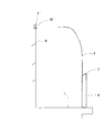
- An upper guide rail 5 extending in the length direction of the platform 1 is extended above the platform 1.
- the upper guide rail 5 extends over substantially the entire length of the platform 1.
- a plurality of upper guide rails may be provided intermittently according to the amount of movement of each movable door pocket 3.
- the upper guide rail 5 extending linearly is shown.
- both the guide rail 2 embedded in the platform 1 and the upper guide rail 5 are loose. It can be formed in a curved shape.
- the lower ends of two support bars 6 as support members are connected to the upper surface 33 of the movable door pocket 3, and the two support bars 6 are parallel to each other in a rising shape upward. It is extended.
- a rotation roller 60 is provided at the upper end of the support bar 6, and the upper end of the support bar 6 is supported so that the rotation roller 60 rolls along the upper guide rail 5 so as to be movable in the length direction of the upper guide rail 5.
- the rotation roller 60 is provided at the upper end of the support bar 6.
- the rotation roller 60 may not be provided as long as the upper end of the support bar 6 can move along the upper guide rail 5.
- the upper end portion of the support bar 6 is used as the upper guide.
- the guide may be guided in direct contact with the rail 5.
- part with which the lower end of the support bar 6 is connected it is not limited to the upper surface 33 of the movable door pocket 3,
- two support bars 6 are shown as long support members, but the number of support bars 6 is not limited, and may be one or three, for example.
- the overall shape and cross-sectional shape of the support bar 6 are not limited, and the cross-sectional shape may be any of a circular shape, a square shape, or another shape.
- the support bar 6 may be a hollow pipe, a non-hollow rod-like member, or a flat belt-like member.
- the support bar 6 is a member that extends substantially vertically as a whole.
- the upper side of the support bar 6 may be greatly curved according to the installation position of the upper guide rail 5.
- An information presentation plate for presenting information between the two support bars 6 may be stretched using the space between the two support bars 6. Examples of information presented on the information presentation plate include route maps, timetables, operation information, and advertisements.
- FIGS. 4 to 6A Several aspects of the support structure of the upper guide rail 5 will be described with reference to FIGS. 4 to 6A.
- guide rails embedded in the floor surface of the platform are omitted.
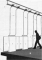
- FIG. 4 shows a case where the upper guide rail 5 is installed on a platform with a roof, and the upper guide rail 5 is supported using the roof. This will be described more specifically.
- a plurality of column bodies 7 are erected on the platform 1, and a roof portion 8 is supported on the upper ends of the column bodies 7.
- the roof portion 8 extends so as to reach above the side edge of the platform 1.
- the upper guide rail 5 is supported on the roof portion 8 by support members 9 and 10. In addition, it may replace with the column body 7 and the structure which supports the roof part 8 with a wall body may be sufficient.
- the lower end of the support bar 6 is fixed to the side of the inclined upper surface 33 of the movable door pocket 3 that is separated from the track (home side A), and the support bar 6 is the home side A (first side) of the upper surface 33 of the movable door pocket 3.
- the upper portion of the rotating portion 60 is provided on the upper end of the bending portion 6 ⁇ / b> A. , 60 are supported by the upper guide rail 5 in a rollable manner. It is understood by those skilled in the art that the support structure (support members 9 and 10), the shape and dimensions of the support bar 6, and the like can be changed as appropriate according to the specific configuration of the roof portion 8.
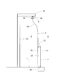
- FIG. 5 shows a case where the upper guide rail 5 is installed on a platform with a ceiling, and the upper guide rail 5 is supported using a ceiling slab.
- a typical platform with a ceiling is an underground platform. This will be described more specifically.
- a ceiling 11 is formed above the platform 1.
- a base frame 12 is provided on the end surface of the ceiling portion 11 on the track side, and an upper guide rail 5 ′ is formed at the lower end of the base frame 12.
- the lower end of the bar 6 is fixed to the side of the inclined upper surface 33 of the movable door pocket 3 that is separated from the track (home side A), and the support bar 6 is the home side A (first surface portion) of the upper surface 33 of the movable door pocket 3.
- the upper portion is a curved portion 6B that is curved to the track side B.
- a rotating roller 60 ' provided at the upper end of the curved portion 6A is provided on the upper guide rail 5'. It is supported so that it can roll. It will be understood by those skilled in the art that the support structure (base frame 12), the shape and dimensions of the support bar, and the like can be changed as appropriate according to the specific configuration of the ceiling portion 11.
- FIG. 5A shows an aspect in which the upper portion of the support bar 6 is extended in the width direction of the platform, and the rotating roller 60 ′′ at the tip is supported by the upper guide rail 5 ′′ provided on the wall body W so as to be able to roll. Show. Alternatively, a dedicated support course may be provided as described below.
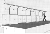
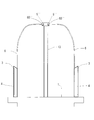
- FIG. 6 shows a case where the upper guide rail 5 is supported using a dedicated support rack installed on the platform 1.
- the dedicated support lecture was supported in a cantilevered manner on a plurality of pillars 13 erected on the floor surface of the platform 1 at intervals in the length direction of the platform 1 and on the upper ends of the pillars 13.
- a transverse member 14 In the illustrated embodiment, the lateral member 14 extends horizontally in the width direction of the platform 1 toward the side edge of the platform 1.
- the upper guide rail 5 is supported on the lower surface on the distal end side of each lateral member 14.
- the structure of the support rack is not limited as long as it can support the upper guide rail 5.
- the lateral member may extend in the length direction of the platform so as to connect the upper ends of the pillars. Good.
- the lower end of the support bar 6 is fixed to the side of the inclined upper surface 33 of the movable door pocket 3 that is separated from the track (home side A), and the support bar 6 is the home side A (first side) of the upper surface 33 of the movable door pocket 3.
- the upper portion of the rotating portion 60 is provided on the upper end of the bending portion 6 ⁇ / b> A. , 60 are supported by the upper guide rail 5 in a rollable manner. It will be understood by those skilled in the art that an appropriate support rack, the shape and dimensions of the support bar, and the like can be appropriately changed according to the conditions of each platform.
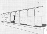
- FIG. 6A shows a modification of the embodiment of FIG.
- a platform without a roof or a platform with a high ceiling / roof such as a dome or an atrium and provided with tracks on both sides in the width direction
- movable platforms on both sides are provided in a platform without a roof or a platform with a high ceiling / roof such as a dome or an atrium and provided with tracks on both sides in the width direction.
- the aspect which the fence shares the column 13 is shown.
- the upper guide rail 5 ′ in which the upper part of the support bar 6 of the movable platform fence on each side extends in a direction approaching each other in the width direction of the platform and the rotating roller 60 ′′ at the tip is provided at the upper end of the column 13. It is supported so that it can roll.
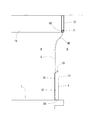
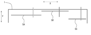
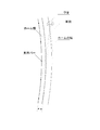
- FIG. 7 is a plan view showing the positional relationship between the platform 1 and the upper guide rails 5A, 5B, and 5C.
- the support structure of the movable door pocket 3 of a plurality of different modes for example, the plurality of modes of FIG. 4 to FIG. 6A described above can be appropriately combined and applied to one platform. This is advantageous when, for example, the structure of the ceiling or roof is not uniform on one platform, or when there is no roof in part.
- the lower end of the support bar 6 is the home of the upper surface 33 of the movable door pouch 3 that is lower than the height of the passenger in the expected direction (thickness direction) of the movable door pouch 3. It is provided on the side A, that is, on the first surface portion 30 side.
- the support bar 6 has a predetermined height including at least the upper body of the passenger on the platform side of the upper surface 33 (for example, from the upper surface 33 of the movable door pocket 3 to the height of 200 cm from the floor surface of the platform 1). It extends vertically upward, and curves toward the home side A or the track side B after approaching the upper end. As shown in FIGS.
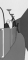
- the field of view from the conductor (the one-dot chain line in FIG. 8A) is widened by setting the position where the support bar 6 extends vertically to the side away from the track of the vehicle.
- the curve is drawn with a steeper curve than the actual curve for the purpose of explaining the effect of expanding the field of view.
- the passenger on the back side shows the passenger left behind between the movable platform fence in the closed state and the vehicle, and the conductor can notice such a situation.
- a bowl-shaped door as disclosed in Patent Document 1
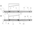
- FIG. 9 is a diagram illustrating a traveling mechanism and a driving method of the movable door pocket.
- (A) shows a ball screw drive system
- (B) shows a belt drive system.
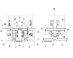
- the lower surface 34 of the movable door pocket 3 has a total of four wheels 35, each having two spaces in the width direction and the expected direction (thickness direction) of the movable door pocket 3. Is provided.
- Each wheel 35 is rotatably supported by a plate-like bracket 36 extending vertically.
- a narrow groove 15 into which a plate-like bracket 36 can be inserted is formed on the floor surface of the platform 1. It is desirable that the groove width of the groove portion 15 is designed so as not to allow passenger shoes or other footwear, the tip of the cane, the roller at the lower end of the bag, or the like to enter.
- Two stopper wheels 37 are disposed on the bracket 36 so as to be positioned in front of and behind the wheel 35.
- the cover 20 is provided above the stopper wheel 37 so as to be supported by the support column 25 so that the upper surface thereof is flush with the floor surface of the platform 1.
- the lower surface of the cover 20 forms a rail for guiding the stopper wheel 37. is doing.
- the wheel 35, the bracket 36, and the stopper wheel 37 form a door pulley assembly. In the door pulley assembly, an upward load (lifting force due to falling of the door pocket) is supported by a stopper wheel 37, and a downward door pocket weight is supported by a wheel 35.
- each movable door pocket 3 needs to be individually driven, and therefore, an independent drive source (motor) and transmission mechanism are prepared for each movable door pocket 3. .
- an independent drive source (motor) and transmission mechanism are prepared for each movable door pocket 3. .
- the four wheels 35 is the driving wheel, which wheel 35 is the driven wheel, or all the wheels 35 are the driving wheels.
- the two front and rear wheels 35 on one side (for example, the track side B) of the four wheels 35 may be driving wheels, and the front and rear two wheels 35 on the other side (home side A) may be driven wheels.
- one motor may be prepared for one movable door pocket.
- the movable door pocket 3 is provided with a control unit that appropriately receives instructions from a management device installed on the platform 1 and controls opening and closing of the movable door pocket 3 and the door body.
- the guide rail 2 in the floor surface of the platform 1 is embedded in the space along the length direction of the guide rail 2 corresponding to each movable door pocket 3.
- a ball screw 16 is extended.
- a slider (ball nut) 17 is externally mounted on the ball screw 16 so as to be movable in the length direction of the ball screw 16, and the slide 17 is fixed to a bracket 36 that supports a wheel 35.
- a terminal bearing 18 is connected to one end side of the ball screw 16, and a motor M is connected to the other end side via a speed reducer 19.
- the slider 17 By selectively rotating the motor M in the forward and reverse directions according to a command from the control unit, the slider 17 is moved in either the left or right direction, the wheel 35 rolls on the guide rail 2, and the movable door pocket 3 is moved to the platform 1. It moves in the length direction.
- the rotation of the motor M stops and the movable door pocket 3 stops.
- the wrapping belt body 21 is extended.
- the belt body 21 is wound around the drive pulley 22 at one end side in the length direction of the guide rail 2, and the belt 21 body is wound around the driven pulley 23 at the other end side. 21A and lower part 21B.
- the bracket 36 that supports the wheel 35 is connected to the upper portion 21 of the belt 21 via the belt clamp 24.
- the drive pulley 22 can be rotated by a motor M.
- the driving pulley 22 is driven to rotate forward and backward by selectively rotating the motor M forward and backward in response to a command from the control unit, and the upper portion 21A of the belt body 21 is moved in either the left or right direction so that the wheels 35 are guided rails. 2, the movable door pocket 3 is moved in the length direction of the platform 1. When the movable door pocket 3 moves to a predetermined position, the rotation of the motor M stops and the movable door pocket 3 stops.
- Patent Literature 3 Patent Literature 4
- the traveling mechanism and drive system of the movable door pocket 3 are also limited to those described here. Rather, it will be understood that those skilled in the art can appropriately design.
- a motor for self-propelling the movable door pocket 3 may be provided on the movable door pocket side.
- the present invention since the upper end side of the movable door pocket 3 is supported by the support bar 6 to prevent the movable door pocket 3 from being shaken, it is necessary to provide a mechanism for preventing the movable door pocket 3 from falling on the traveling mechanism side. It should be noted that the configuration of the traveling mechanism can be simplified as much as possible.
- the rotating roller 60 at the upper end of the support bar 6 rolls along the upper guide rail 5,
- the support bar 6 moves integrally in the length direction of the platform 1. Since the upper swing and movement of the movable door pocket 3 during the movement of the movable door pocket 3 are absorbed by the support bar 6 guided by the upper guide rail 5, the movable door pocket 3 can be driven stably.
- the upper end of the movable door pocket 3 can be moved to the upper guide rail 5 even when the movable door pocket 3 moves or is stationary when wind pressure acts on the movable door pocket 3 or a person hits it. Therefore, the movable door pocket 3 does not fall down.
- the present invention can be used as a movable platform fence installed on a platform.
Landscapes
- Engineering & Computer Science (AREA)
- Transportation (AREA)
- Mechanical Engineering (AREA)
- Platform Screen Doors And Railroad Systems (AREA)
- Refuge Islands, Traffic Blockers, Or Guard Fence (AREA)
Priority Applications (1)
| Application Number | Priority Date | Filing Date | Title |
|---|---|---|---|
| EP20100813618 EP2474458A4 (en) | 2009-09-01 | 2010-08-17 | AUTOMATIC PLATFORM GATES |
Applications Claiming Priority (2)
| Application Number | Priority Date | Filing Date | Title |
|---|---|---|---|
| JP2009-202107 | 2009-09-01 | ||
| JP2009202107A JP5317281B2 (ja) | 2009-09-01 | 2009-09-01 | 可動ホーム柵 |
Publications (1)
| Publication Number | Publication Date |
|---|---|
| WO2011027667A1 true WO2011027667A1 (ja) | 2011-03-10 |
Family
ID=43649208
Family Applications (1)
| Application Number | Title | Priority Date | Filing Date |
|---|---|---|---|
| PCT/JP2010/063837 Ceased WO2011027667A1 (ja) | 2009-09-01 | 2010-08-17 | 可動ホーム柵 |
Country Status (3)
| Country | Link |
|---|---|
| EP (1) | EP2474458A4 (enExample) |
| JP (1) | JP5317281B2 (enExample) |
| WO (1) | WO2011027667A1 (enExample) |
Cited By (1)
| Publication number | Priority date | Publication date | Assignee | Title |
|---|---|---|---|---|
| WO2013104356A1 (de) * | 2012-01-09 | 2013-07-18 | Pintsch Bamag Antriebs- Und Verkehrstechnik Gmbh | Bahnsteigtürsystem, verfahren zum betreiben eines bahnsteigtürsystems und türrahmen für ein bahnsteigtürsystem |
Families Citing this family (6)
| Publication number | Priority date | Publication date | Assignee | Title |
|---|---|---|---|---|
| JP5524265B2 (ja) * | 2012-03-23 | 2014-06-18 | 株式会社京三製作所 | ホーム柵 |
| JP5841892B2 (ja) * | 2012-04-19 | 2016-01-13 | 株式会社神戸製鋼所 | プラットホームドア装置 |
| JP5923006B2 (ja) * | 2012-07-19 | 2016-05-24 | 株式会社京三製作所 | ホーム柵、及びホーム柵システム |
| US10589754B2 (en) * | 2016-05-09 | 2020-03-17 | Tal LEIZER | Train platform located security system |
| CN111547071B (zh) * | 2020-05-25 | 2021-07-06 | 成都唐源电气股份有限公司 | 一种开门位置可调的高铁站台门 |
| CN114559963B (zh) * | 2022-01-29 | 2023-07-14 | 扬州尚呈标识系统设计有限公司 | 一种用于站台的两段式全移动围栏小车 |
Citations (8)
| Publication number | Priority date | Publication date | Assignee | Title |
|---|---|---|---|---|
| JP2000108889A (ja) * | 1998-10-01 | 2000-04-18 | Fuji Electric Co Ltd | プラットホーム用開閉柵 |
| JP2000142384A (ja) * | 1998-11-17 | 2000-05-23 | Kawasaki Heavy Ind Ltd | プラットホーム防護壁の設置構造 |
| JP2004131009A (ja) | 2002-10-11 | 2004-04-30 | Kyosan Electric Mfg Co Ltd | 可動ホーム柵装置 |
| JP2005145372A (ja) | 2003-11-19 | 2005-06-09 | Hitachi Ltd | 異種車両対応フレキシブル可動柵 |
| JP2005335451A (ja) | 2004-05-25 | 2005-12-08 | Mitsubishi Electric Corp | 可動式ホーム柵装置 |
| JP2006008068A (ja) | 2004-06-29 | 2006-01-12 | East Japan Railway Co | 自走式可動プラットホームゲート |
| JP2006008069A (ja) * | 2004-06-29 | 2006-01-12 | East Japan Railway Co | プラットホームゲートシステム |
| JP2007030659A (ja) * | 2005-07-26 | 2007-02-08 | East Japan Railway Co | プラットホームゲートシステム |
-
2009
- 2009-09-01 JP JP2009202107A patent/JP5317281B2/ja active Active
-
2010
- 2010-08-17 WO PCT/JP2010/063837 patent/WO2011027667A1/ja not_active Ceased
- 2010-08-17 EP EP20100813618 patent/EP2474458A4/en not_active Withdrawn
Patent Citations (8)
| Publication number | Priority date | Publication date | Assignee | Title |
|---|---|---|---|---|
| JP2000108889A (ja) * | 1998-10-01 | 2000-04-18 | Fuji Electric Co Ltd | プラットホーム用開閉柵 |
| JP2000142384A (ja) * | 1998-11-17 | 2000-05-23 | Kawasaki Heavy Ind Ltd | プラットホーム防護壁の設置構造 |
| JP2004131009A (ja) | 2002-10-11 | 2004-04-30 | Kyosan Electric Mfg Co Ltd | 可動ホーム柵装置 |
| JP2005145372A (ja) | 2003-11-19 | 2005-06-09 | Hitachi Ltd | 異種車両対応フレキシブル可動柵 |
| JP2005335451A (ja) | 2004-05-25 | 2005-12-08 | Mitsubishi Electric Corp | 可動式ホーム柵装置 |
| JP2006008068A (ja) | 2004-06-29 | 2006-01-12 | East Japan Railway Co | 自走式可動プラットホームゲート |
| JP2006008069A (ja) * | 2004-06-29 | 2006-01-12 | East Japan Railway Co | プラットホームゲートシステム |
| JP2007030659A (ja) * | 2005-07-26 | 2007-02-08 | East Japan Railway Co | プラットホームゲートシステム |
Non-Patent Citations (1)
| Title |
|---|
| See also references of EP2474458A4 * |
Cited By (2)
| Publication number | Priority date | Publication date | Assignee | Title |
|---|---|---|---|---|
| WO2013104356A1 (de) * | 2012-01-09 | 2013-07-18 | Pintsch Bamag Antriebs- Und Verkehrstechnik Gmbh | Bahnsteigtürsystem, verfahren zum betreiben eines bahnsteigtürsystems und türrahmen für ein bahnsteigtürsystem |
| US9266538B2 (en) | 2012-01-09 | 2016-02-23 | Pintsch Bamag Antriebs-Und Verkehrstechnik Gmbh | Platform door system, method for operating a platform door system and door frame for a platform door system |
Also Published As
| Publication number | Publication date |
|---|---|
| EP2474458A4 (en) | 2014-09-24 |
| JP2011051471A (ja) | 2011-03-17 |
| EP2474458A1 (en) | 2012-07-11 |
| JP5317281B2 (ja) | 2013-10-16 |
Similar Documents
| Publication | Publication Date | Title |
|---|---|---|
| JP5499338B2 (ja) | 可動ホーム柵 | |
| JP5317281B2 (ja) | 可動ホーム柵 | |
| CN202108407U (zh) | 可伸缩式平移门的电缆布线结构 | |
| JP4700643B2 (ja) | ボーディングブリッジ | |
| KR101218339B1 (ko) | 다층 주차 장치 | |
| US7686697B2 (en) | Amusement ride | |
| JPS61222875A (ja) | スポイラ−装置 | |
| JP6085458B2 (ja) | ホーム安全柵 | |
| EP1781521B1 (en) | A monorail vehicle | |
| JP2019194048A (ja) | ホームドア | |
| CN203716551U (zh) | 无避让升降式停车库 | |
| CN101748916A (zh) | 路边停车仓 | |
| US7927223B2 (en) | Amusement ride | |
| CN108386033B (zh) | 一种二层无避让停车装置 | |
| KR101401027B1 (ko) | 컨테이너형 덮개장치 | |
| KR20120135659A (ko) | 높이 확장형 경광등 | |
| JP4950857B2 (ja) | 伸縮長さ調整用搭乗橋 | |
| WO2018137017A1 (en) | Overhead storage unit | |
| JP4802887B2 (ja) | 移動式間仕切装置 | |
| JP2787201B2 (ja) | プラットホームスクリーンドア | |
| CN103643817A (zh) | 一种地坑内车辆升降系统 | |
| KR200389410Y1 (ko) | 지하철용 스크린도어 개폐장치 | |
| JP7545299B2 (ja) | 機械式駐車場の入庫案内装置 | |
| JPH1046966A (ja) | 門扉装置 | |
| RU65537U1 (ru) | Механизированная стоянка вертикального типа |
Legal Events
| Date | Code | Title | Description |
|---|---|---|---|
| 121 | Ep: the epo has been informed by wipo that ep was designated in this application |
Ref document number: 10813618 Country of ref document: EP Kind code of ref document: A1 |
|
| NENP | Non-entry into the national phase |
Ref country code: DE |
|
| WWE | Wipo information: entry into national phase |
Ref document number: 2010813618 Country of ref document: EP |