WO2011027662A1 - Palier à roulement rendu étanche - Google Patents
Palier à roulement rendu étanche Download PDFInfo
- Publication number
- WO2011027662A1 WO2011027662A1 PCT/JP2010/063739 JP2010063739W WO2011027662A1 WO 2011027662 A1 WO2011027662 A1 WO 2011027662A1 JP 2010063739 W JP2010063739 W JP 2010063739W WO 2011027662 A1 WO2011027662 A1 WO 2011027662A1
- Authority
- WO
- WIPO (PCT)
- Prior art keywords
- rolling bearing
- cage
- sealed
- sealing plate
- outer ring
- Prior art date
Links
Images

Classifications
-
- F—MECHANICAL ENGINEERING; LIGHTING; HEATING; WEAPONS; BLASTING
- F16—ENGINEERING ELEMENTS AND UNITS; GENERAL MEASURES FOR PRODUCING AND MAINTAINING EFFECTIVE FUNCTIONING OF MACHINES OR INSTALLATIONS; THERMAL INSULATION IN GENERAL
- F16C—SHAFTS; FLEXIBLE SHAFTS; ELEMENTS OR CRANKSHAFT MECHANISMS; ROTARY BODIES OTHER THAN GEARING ELEMENTS; BEARINGS
- F16C19/00—Bearings with rolling contact, for exclusively rotary movement
- F16C19/52—Bearings with rolling contact, for exclusively rotary movement with devices affected by abnormal or undesired conditions
-
- F—MECHANICAL ENGINEERING; LIGHTING; HEATING; WEAPONS; BLASTING
- F16—ENGINEERING ELEMENTS AND UNITS; GENERAL MEASURES FOR PRODUCING AND MAINTAINING EFFECTIVE FUNCTIONING OF MACHINES OR INSTALLATIONS; THERMAL INSULATION IN GENERAL
- F16C—SHAFTS; FLEXIBLE SHAFTS; ELEMENTS OR CRANKSHAFT MECHANISMS; ROTARY BODIES OTHER THAN GEARING ELEMENTS; BEARINGS
- F16C23/00—Bearings for exclusively rotary movement adjustable for aligning or positioning
- F16C23/06—Ball or roller bearings
- F16C23/08—Ball or roller bearings self-adjusting
- F16C23/082—Ball or roller bearings self-adjusting by means of at least one substantially spherical surface
- F16C23/086—Ball or roller bearings self-adjusting by means of at least one substantially spherical surface forming a track for rolling elements
-
- F—MECHANICAL ENGINEERING; LIGHTING; HEATING; WEAPONS; BLASTING
- F16—ENGINEERING ELEMENTS AND UNITS; GENERAL MEASURES FOR PRODUCING AND MAINTAINING EFFECTIVE FUNCTIONING OF MACHINES OR INSTALLATIONS; THERMAL INSULATION IN GENERAL
- F16C—SHAFTS; FLEXIBLE SHAFTS; ELEMENTS OR CRANKSHAFT MECHANISMS; ROTARY BODIES OTHER THAN GEARING ELEMENTS; BEARINGS
- F16C33/00—Parts of bearings; Special methods for making bearings or parts thereof
- F16C33/30—Parts of ball or roller bearings
- F16C33/46—Cages for rollers or needles
- F16C33/48—Cages for rollers or needles for multiple rows of rollers or needles
- F16C33/485—Cages for rollers or needles for multiple rows of rollers or needles with two or more juxtaposed cages joined together or interacting with each other
-
- F—MECHANICAL ENGINEERING; LIGHTING; HEATING; WEAPONS; BLASTING
- F16—ENGINEERING ELEMENTS AND UNITS; GENERAL MEASURES FOR PRODUCING AND MAINTAINING EFFECTIVE FUNCTIONING OF MACHINES OR INSTALLATIONS; THERMAL INSULATION IN GENERAL
- F16C—SHAFTS; FLEXIBLE SHAFTS; ELEMENTS OR CRANKSHAFT MECHANISMS; ROTARY BODIES OTHER THAN GEARING ELEMENTS; BEARINGS
- F16C33/00—Parts of bearings; Special methods for making bearings or parts thereof
- F16C33/30—Parts of ball or roller bearings
- F16C33/66—Special parts or details in view of lubrication
-
- F—MECHANICAL ENGINEERING; LIGHTING; HEATING; WEAPONS; BLASTING
- F16—ENGINEERING ELEMENTS AND UNITS; GENERAL MEASURES FOR PRODUCING AND MAINTAINING EFFECTIVE FUNCTIONING OF MACHINES OR INSTALLATIONS; THERMAL INSULATION IN GENERAL
- F16C—SHAFTS; FLEXIBLE SHAFTS; ELEMENTS OR CRANKSHAFT MECHANISMS; ROTARY BODIES OTHER THAN GEARING ELEMENTS; BEARINGS
- F16C33/00—Parts of bearings; Special methods for making bearings or parts thereof
- F16C33/72—Sealings
- F16C33/76—Sealings of ball or roller bearings
- F16C33/78—Sealings of ball or roller bearings with a diaphragm, disc, or ring, with or without resilient members
- F16C33/7803—Sealings of ball or roller bearings with a diaphragm, disc, or ring, with or without resilient members suited for particular types of rolling bearings
- F16C33/7806—Sealings of ball or roller bearings with a diaphragm, disc, or ring, with or without resilient members suited for particular types of rolling bearings for spherical roller bearings
-
- F—MECHANICAL ENGINEERING; LIGHTING; HEATING; WEAPONS; BLASTING
- F16—ENGINEERING ELEMENTS AND UNITS; GENERAL MEASURES FOR PRODUCING AND MAINTAINING EFFECTIVE FUNCTIONING OF MACHINES OR INSTALLATIONS; THERMAL INSULATION IN GENERAL
- F16C—SHAFTS; FLEXIBLE SHAFTS; ELEMENTS OR CRANKSHAFT MECHANISMS; ROTARY BODIES OTHER THAN GEARING ELEMENTS; BEARINGS
- F16C33/00—Parts of bearings; Special methods for making bearings or parts thereof
- F16C33/72—Sealings
- F16C33/76—Sealings of ball or roller bearings
- F16C33/78—Sealings of ball or roller bearings with a diaphragm, disc, or ring, with or without resilient members
- F16C33/7893—Sealings of ball or roller bearings with a diaphragm, disc, or ring, with or without resilient members mounted to a cage or integral therewith
-
- F—MECHANICAL ENGINEERING; LIGHTING; HEATING; WEAPONS; BLASTING
- F16—ENGINEERING ELEMENTS AND UNITS; GENERAL MEASURES FOR PRODUCING AND MAINTAINING EFFECTIVE FUNCTIONING OF MACHINES OR INSTALLATIONS; THERMAL INSULATION IN GENERAL
- F16C—SHAFTS; FLEXIBLE SHAFTS; ELEMENTS OR CRANKSHAFT MECHANISMS; ROTARY BODIES OTHER THAN GEARING ELEMENTS; BEARINGS
- F16C41/00—Other accessories, e.g. devices integrated in the bearing not relating to the bearing function as such
- F16C41/008—Identification means, e.g. markings, RFID-tags; Data transfer means
-
- F—MECHANICAL ENGINEERING; LIGHTING; HEATING; WEAPONS; BLASTING
- F16—ENGINEERING ELEMENTS AND UNITS; GENERAL MEASURES FOR PRODUCING AND MAINTAINING EFFECTIVE FUNCTIONING OF MACHINES OR INSTALLATIONS; THERMAL INSULATION IN GENERAL
- F16C—SHAFTS; FLEXIBLE SHAFTS; ELEMENTS OR CRANKSHAFT MECHANISMS; ROTARY BODIES OTHER THAN GEARING ELEMENTS; BEARINGS
- F16C19/00—Bearings with rolling contact, for exclusively rotary movement
- F16C19/22—Bearings with rolling contact, for exclusively rotary movement with bearing rollers essentially of the same size in one or more circular rows, e.g. needle bearings
- F16C19/34—Bearings with rolling contact, for exclusively rotary movement with bearing rollers essentially of the same size in one or more circular rows, e.g. needle bearings for both radial and axial load
- F16C19/38—Bearings with rolling contact, for exclusively rotary movement with bearing rollers essentially of the same size in one or more circular rows, e.g. needle bearings for both radial and axial load with two or more rows of rollers
-
- F—MECHANICAL ENGINEERING; LIGHTING; HEATING; WEAPONS; BLASTING
- F16—ENGINEERING ELEMENTS AND UNITS; GENERAL MEASURES FOR PRODUCING AND MAINTAINING EFFECTIVE FUNCTIONING OF MACHINES OR INSTALLATIONS; THERMAL INSULATION IN GENERAL
- F16C—SHAFTS; FLEXIBLE SHAFTS; ELEMENTS OR CRANKSHAFT MECHANISMS; ROTARY BODIES OTHER THAN GEARING ELEMENTS; BEARINGS
- F16C2226/00—Joining parts; Fastening; Assembling or mounting parts
- F16C2226/30—Material joints
- F16C2226/40—Material joints with adhesive
-
- F—MECHANICAL ENGINEERING; LIGHTING; HEATING; WEAPONS; BLASTING
- F16—ENGINEERING ELEMENTS AND UNITS; GENERAL MEASURES FOR PRODUCING AND MAINTAINING EFFECTIVE FUNCTIONING OF MACHINES OR INSTALLATIONS; THERMAL INSULATION IN GENERAL
- F16C—SHAFTS; FLEXIBLE SHAFTS; ELEMENTS OR CRANKSHAFT MECHANISMS; ROTARY BODIES OTHER THAN GEARING ELEMENTS; BEARINGS
- F16C2233/00—Monitoring condition, e.g. temperature, load, vibration
Definitions
- This invention relates to a sealed type rolling bearing having a function of preventing entry of foreign matter.
- Sealed rolling bearings have a sealing plate that is press-fitted on both sides of the raceway of one of the inner and outer races facing the inside and outside of the rolling element, and each seal plate is placed on both sides of the raceway of the other raceway.
- the structure which makes the free end part contact or approach is taken (patent document 1).
- the sealing plate has a function of preventing the internal lubricant from leaking outside, in addition to the function of preventing the entry of foreign matter from the outside into the bearing.
- a rubber seal with a cored bar is used for the type of sealing plate in which the free end of the sealing plate is brought into contact with the mating raceway.
- a metal plate is used in the non-contact type sealing plate.
- Patent Document 3 a rolling bearing in which the sealing plate is screwed to a cage is known.
- An object of the invention related to the rolling bearing is to eliminate the possibility of deformation of the sealing plate or the inner and outer rings when the sealing plate is press-fitted into the inner diameter surface of the outer ring or the outer diameter surface of the inner ring.
- the sealing plate is attached to the bearing retainer by screwing, and the inner and outer peripheral edges of the sealing plate are brought into contact with or close to the outer ring inner diameter surface and the inner ring outer diameter surface.
- the present invention makes the bearing size compatible with the non-sealed type rolling bearing by reducing the mounting space of the sealing plate in the sealed type rolling bearing to substantially zero, and from the outside of the bearing. It is an object of the present invention to provide a hermetic rolling bearing capable of visually observing the color of a lubricant.
- the present invention includes an inner ring and an outer ring, a large number of rolling elements interposed between the inner ring raceway and the outer ring raceway, a rolling bearing body including a holder for the rolling element, and the rolling
- a sealing type rolling bearing comprising an inner ring raceway of a bearing body and a sealing member provided between outer end portions of an outer ring raceway, the sealing member is formed of a transparent plastic sealing plate and attached to the cage Is adopted.
- the mounting space for the sealing plate is substantially zero on both sides of the raceway grooves of the inner and outer rings, so the bearing size is made the same as that of the non-sealing type.
- the concentration of the lubricant in contact with the inside of the sealing plate can be visually observed from the outside, an effect of quickly determining the deterioration state of the lubricant is also exhibited.
- the sealing plate is formed of a single transparent synthetic resin plate, there is an advantage that it is lighter and lower in cost than those using conventional rubber or metal plates.
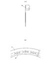
- the rolling bearing shown in FIG. 1 is a self-aligning roller bearing.
- This bearing holds and guides an inner ring 11 and an outer ring 12 that are coaxially arranged inside and outside, a large number of rollers 13 arranged in two rows between the inner and outer races, and the rollers 13 at equal intervals in the circumferential direction.
- a bearing body is constituted by the cage 14.
- a sealed self-aligning roller bearing is constituted by the bearing body and a pair of transparent sealing plates 15 attached to the left and right sides of the inner and outer rings 11 and 12.
- the size of the bearing body excluding the sealing plate 15 is the same as that of a non-sealing self-aligning roller bearing, that is, a self-aligning roller bearing of a type that does not use a sealing plate.
- an outer ring raceway 16 made of a concave spherical surface centered on the bearing center is formed. Further, inner ring raceways 17, 17 composed of two rows of concave spherical surfaces facing the outer ring raceway 16 are provided on the outer diameter surface of the inner ring 11. A flat portion 18 having a slight width rising from both inner ring raceways 17 and 17 along the spherical surface is formed between the inner peripheral portions of both inner ring raceways 17 and 17.
- the barrel-shaped rollers 13 each having a spherical surface are interposed.
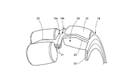
- the cage 14 is a squirrel-cage cage made of a steel plate, and as shown in FIGS. 1 and 3, the left cage 14 a disposed on the outer surface of the left inner ring raceway 17 and the right inner ring raceway 17.
- the right cage 14b disposed on the outer surface of the right and left sides is formed symmetrically.
- Each of the cages 14a and 14b includes an inner ring 21 and an outer ring 22 that face each other in the axial direction, and a column portion 23 that connects the two in the axial direction.
- the column portions 23 are spaced apart from each other in the circumferential direction. Many are provided.
- a rectangular pocket 24 is formed between the pillar portions 23, and one roller 13 is stored and held in each pocket 24.
- the inner peripheral surface of the outer ring 22 is brought into contact with the inner ring raceway 17 (see FIG. 1). By this contact, the cage 14 becomes an inner ring guide type guided by the inner ring 11.
- the outer ring 22 is provided so as to be in contact with the inner ring raceway 17, so that the outer ring 22 closes about half between the inner and outer rings 11 and 12. For this reason, in order to seal the bearing, the other half open portion may be closed by the sealing plate 15.
- the sealing plate 15 of the embodiment is an annular transparent plate made of synthetic resin such as PET, and a closing portion a (see FIG. 2) that closes the open portion is formed along the outer peripheral edge, and an outer ring is formed inside the closing portion.
- 22 is an annular member in which a reinforcing part c is provided inside the adhesive part b and the adhesive part b.
- the reinforced portion c is increased in width to increase the strength of the sealing plate 15 and facilitate handling.
- the sealing plate 15 is attached by bonding the bonding portion b to the outer surface of the outer ring 22.
- the outer peripheral edge of the closed portion a is positioned with respect to the outer ring raceway 16 in a non-contact state with a slight gap that does not lose the sealing performance.
- a contact type may be employ
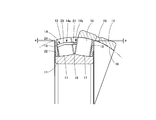
- the assembly of the inner ring 11, the roller 13 and the cage 14 is aligned in the opposite direction with respect to the outer ring 12 in order to check the inside of the bearing.
- the roller 13 is deformed to be exposed, that is, so-called “abdomen” is performed.
- the outer peripheral edge of the sealing plate 15 is on the extension line of the arc of the outer ring raceway 16 (see the one-dot chain line in FIG. 1) or on the outer ring 12 side in the cross section including the axis of the outer ring 12. In this case, since the sealing plate 15 interferes with the outer ring 12, the stomach cannot be laid out.
- the outer peripheral edge of the sealing plate 15 is predetermined on the axial side from the extension line of the arc of the outer ring raceway 16 in the cross section including the axis of the outer ring 12 (see the one-dot chain line in FIG. 4).
- the gap “a” By providing the gap “a”, the above-described interference can be avoided and the abdomen can be raised.
- the gap a By setting the gap a to a minimum size that does not impair sealing, sealing performance can be maintained.
- the outer surface of the sealing plate 15 is colored along the blocking portion a over the portion corresponding to the bonding portion b or both the bonding portion b and the reinforcing portion c.
- a sample seal 25 is adhered.
- Each color sample seal 25 is provided with a rank display such as A, B, C, etc., which indicates the degradation state of the lubricant according to the rank according to the color density of the lubricant.
- symbol 26 shows the injection hole of a lubricant.
- the sealed self-aligning roller bearing of the embodiment is as described above, and is used in the same manner as in the prior art, and the relative alignment at the bearing center between the shaft on the inner ring 11 side and the housing on the outer ring 12 side is performed. Allow. Intrusion of foreign matter from the outside is prevented by the closing plate 15 and the outer ring 22 of the retainer 14, and at the same time, leakage of the lubricant is prevented.
- the lubricant fills the inside of the bearing, and a part of the lubricant comes into contact with the inner surface of the closed portion a of the sealing plate 15.
- the internal lubricant can be visually observed from the outside through the blocking portion a.
- the rank of the deterioration state of the lubricant can be determined.
- this invention can be applied not only to a general roller bearing without self-alignment but also to a rolling bearing such as a ball bearing.
Landscapes
- Engineering & Computer Science (AREA)
- General Engineering & Computer Science (AREA)
- Mechanical Engineering (AREA)
- Rolling Contact Bearings (AREA)
- Support Of The Bearing (AREA)
- Sealing Of Bearings (AREA)
Abstract
La présente invention concerne un palier à roulement rendu étanche configuré de telle manière que la configuration des plaques d'étanchéité de manière à ce sorte qu'elles nécessitent sensiblement moins d'espace de montage dans le palier à roulement de palier rendu étanche a pour conséquence que le palier de à roulement rendu étanche présente une dimension permettant au palier de à roulement rendu étanche d'être interchangeable avec le un palier de roulement non rendu étanche et que la couleur de l'agent lubrifiant puisse peu être observée visuellement depuis l'extérieur du palier de à roulement rendu étanche.
Un palier de à roulement rendu étanche est pourvu : d'un corps de palier de à roulement ; et d'éléments d'étanchéité disposés chacun entre les extrémités extérieures du chemin de roulement de la bague couronne intérieure (17) et du chemin de roulement de la bague couronne extérieure (16) du corps du palier à roulement de palier. Les éléments d'étanchéité sont constitués de plaques d'étanchéité transparentes en plastique (15) et sont montés sur le dispositif de retenue (14).
Priority Applications (2)
| Application Number | Priority Date | Filing Date | Title |
|---|---|---|---|
| US13/394,224 US20120163745A1 (en) | 2009-09-07 | 2010-08-13 | Sealed rolling bearing |
| EP10813613A EP2476926A1 (fr) | 2009-09-07 | 2010-08-13 | Palier à roulement rendu étanche |
Applications Claiming Priority (2)
| Application Number | Priority Date | Filing Date | Title |
|---|---|---|---|
| JP2009205394A JP2011058508A (ja) | 2009-09-07 | 2009-09-07 | 密封型転がり軸受 |
| JP2009-205394 | 2009-09-07 |
Publications (1)
| Publication Number | Publication Date |
|---|---|
| WO2011027662A1 true WO2011027662A1 (fr) | 2011-03-10 |
Family
ID=43649204
Family Applications (1)
| Application Number | Title | Priority Date | Filing Date |
|---|---|---|---|
| PCT/JP2010/063739 WO2011027662A1 (fr) | 2009-09-07 | 2010-08-13 | Palier à roulement rendu étanche |
Country Status (4)
| Country | Link |
|---|---|
| US (1) | US20120163745A1 (fr) |
| EP (1) | EP2476926A1 (fr) |
| JP (1) | JP2011058508A (fr) |
| WO (1) | WO2011027662A1 (fr) |
Cited By (4)
| Publication number | Priority date | Publication date | Assignee | Title |
|---|---|---|---|---|
| EP2808570A1 (fr) | 2013-05-31 | 2014-12-03 | NTN-SNR Roulements | Roulement muni d'un système d'étanchéité |
| US20150176652A1 (en) * | 2013-12-19 | 2015-06-25 | Aktiebolaget Skf | Rolling-element bearing including seal unit |
| EP3029344A1 (fr) | 2014-12-01 | 2016-06-08 | NTN-SNR Roulements | Pièce et système d'étanchéité pour roulements, et roulement muni de tels pièces et systèmes |
| DE102017116875A1 (de) * | 2017-07-26 | 2019-01-31 | Thyssenkrupp Ag | Kombination eines Wälzlagers und mindestens eines Abdeckelements sowie Walzenmühle |
Families Citing this family (8)
| Publication number | Priority date | Publication date | Assignee | Title |
|---|---|---|---|---|
| EP2904282B1 (fr) * | 2012-10-04 | 2020-01-22 | Aktiebolaget SKF | Cage de roulement& palier à roulement |
| CN104781567A (zh) * | 2012-10-04 | 2015-07-15 | Skf公司 | 润滑滚动元件轴承的方法 |
| CN104718388A (zh) * | 2012-10-04 | 2015-06-17 | Skf公司 | 轴承保持架和滚动元件轴承 |
| CN111701248A (zh) * | 2014-07-09 | 2020-09-25 | H·迈尔 | 用于观景摩天轮的可居住支撑结构 |
| US10082179B2 (en) | 2014-12-16 | 2018-09-25 | Roller Bearing Company Of America, Inc. | Seal for self aligning roller bearing |
| JP2016161037A (ja) * | 2015-03-02 | 2016-09-05 | Ntn株式会社 | 自動調心ころ軸受 |
| FR3052831B1 (fr) * | 2016-06-20 | 2018-07-27 | Ntn-Snr Roulements | Procede d’etancheification d’un palier a roulement et palier a roulement ainsi obtenu |
| JP2019215058A (ja) * | 2018-06-14 | 2019-12-19 | Ntn株式会社 | 自動調心ころ軸受 |
Citations (5)
| Publication number | Priority date | Publication date | Assignee | Title |
|---|---|---|---|---|
| JPH0712736Y2 (ja) | 1987-11-10 | 1995-03-29 | 日本精工株式会社 | 自動調心ころ軸受 |
| JPH09317760A (ja) | 1996-05-30 | 1997-12-09 | Ntn Corp | 自動調心ころ軸受 |
| JP2003161318A (ja) * | 2001-07-10 | 2003-06-06 | Nsk Ltd | 軸受装置 |
| JP2003202023A (ja) * | 2002-01-08 | 2003-07-18 | Nsk Ltd | 玉軸受および軸受装置 |
| JP2007198540A (ja) | 2006-01-27 | 2007-08-09 | Nsk Ltd | シール付き転がり軸受 |
Family Cites Families (6)
| Publication number | Priority date | Publication date | Assignee | Title |
|---|---|---|---|---|
| US3981550A (en) * | 1975-01-20 | 1976-09-21 | Borg-Warner Corporation | Bearing improvement |
| JPS6363967A (ja) * | 1986-09-05 | 1988-03-22 | Toshiba Corp | 潤滑油劣化判定方法 |
| JPH01141231A (ja) * | 1987-11-24 | 1989-06-02 | Nec Corp | 軸受 |
| DE8904504U1 (fr) * | 1989-04-11 | 1989-05-18 | Fag Kugelfischer Georg Schaefer Kgaa, 8720 Schweinfurt, De | |
| JP3477835B2 (ja) * | 1993-10-12 | 2003-12-10 | 日本精工株式会社 | 保持器付自動調心ころ軸受 |
| JP2006177715A (ja) * | 2004-12-21 | 2006-07-06 | Jtekt Corp | 潤滑剤監視装置 |
-
2009
- 2009-09-07 JP JP2009205394A patent/JP2011058508A/ja not_active Withdrawn
-
2010
- 2010-08-13 US US13/394,224 patent/US20120163745A1/en not_active Abandoned
- 2010-08-13 WO PCT/JP2010/063739 patent/WO2011027662A1/fr active Application Filing
- 2010-08-13 EP EP10813613A patent/EP2476926A1/fr not_active Withdrawn
Patent Citations (5)
| Publication number | Priority date | Publication date | Assignee | Title |
|---|---|---|---|---|
| JPH0712736Y2 (ja) | 1987-11-10 | 1995-03-29 | 日本精工株式会社 | 自動調心ころ軸受 |
| JPH09317760A (ja) | 1996-05-30 | 1997-12-09 | Ntn Corp | 自動調心ころ軸受 |
| JP2003161318A (ja) * | 2001-07-10 | 2003-06-06 | Nsk Ltd | 軸受装置 |
| JP2003202023A (ja) * | 2002-01-08 | 2003-07-18 | Nsk Ltd | 玉軸受および軸受装置 |
| JP2007198540A (ja) | 2006-01-27 | 2007-08-09 | Nsk Ltd | シール付き転がり軸受 |
Cited By (5)
| Publication number | Priority date | Publication date | Assignee | Title |
|---|---|---|---|---|
| EP2808570A1 (fr) | 2013-05-31 | 2014-12-03 | NTN-SNR Roulements | Roulement muni d'un système d'étanchéité |
| US20150176652A1 (en) * | 2013-12-19 | 2015-06-25 | Aktiebolaget Skf | Rolling-element bearing including seal unit |
| US9739313B2 (en) * | 2013-12-19 | 2017-08-22 | Aktiebolaget Skf | Rolling-element bearing including seal unit |
| EP3029344A1 (fr) | 2014-12-01 | 2016-06-08 | NTN-SNR Roulements | Pièce et système d'étanchéité pour roulements, et roulement muni de tels pièces et systèmes |
| DE102017116875A1 (de) * | 2017-07-26 | 2019-01-31 | Thyssenkrupp Ag | Kombination eines Wälzlagers und mindestens eines Abdeckelements sowie Walzenmühle |
Also Published As
| Publication number | Publication date |
|---|---|
| EP2476926A1 (fr) | 2012-07-18 |
| US20120163745A1 (en) | 2012-06-28 |
| JP2011058508A (ja) | 2011-03-24 |
Similar Documents
| Publication | Publication Date | Title |
|---|---|---|
| WO2011027662A1 (fr) | Palier à roulement rendu étanche | |
| JP4255969B2 (ja) | ベアリングローラチェーン | |
| JP2008133871A (ja) | ベアリングローラチェーン | |
| JP2007198540A (ja) | シール付き転がり軸受 | |
| WO2016125516A1 (fr) | Dispositif de roulement pour véhicule ferroviaire | |
| JP2005076660A (ja) | 転がり軸受装置 | |
| US20160017926A1 (en) | Bearing device with sealing device | |
| US9752620B2 (en) | Dynamically aligning, maintenance free, radial insert ball bearing | |
| JP6282609B2 (ja) | 転がり軸受 | |
| CN109661523B (zh) | 车轴用轴承装置 | |
| CN111936757B (zh) | 车轮用轴承装置 | |
| GB2566208A (en) | Roller bearing apparatus | |
| JP2005325867A (ja) | 鉄道車両用軸受 | |
| JP2005226787A (ja) | 軸受用密封装置 | |
| JP2007285477A (ja) | シールチェーン | |
| JP6396681B2 (ja) | 車輪用軸受装置 | |
| JP6024291B2 (ja) | 転がり軸受 | |
| JP2018002148A (ja) | 車輪用軸受装置 | |
| US10323691B2 (en) | Needle bush bearing with sealing device | |
| KR102580857B1 (ko) | 씰링성이 향상된 구름 베어링 | |
| US11499605B2 (en) | Seal chain | |
| JP2015183712A (ja) | 軸受装置 | |
| JP6866567B2 (ja) | 自動調心ころ軸受 | |
| JP2012241819A (ja) | 水ポンプ用軸受装置 | |
| WO2017179580A1 (fr) | Palier à double rangée et palier à rouleaux de complément complet |
Legal Events
| Date | Code | Title | Description |
|---|---|---|---|
| 121 | Ep: the epo has been informed by wipo that ep was designated in this application |
Ref document number: 10813613 Country of ref document: EP Kind code of ref document: A1 |
|
| WWE | Wipo information: entry into national phase |
Ref document number: 13394224 Country of ref document: US |
|
| WWE | Wipo information: entry into national phase |
Ref document number: 2010813613 Country of ref document: EP |
|
| NENP | Non-entry into the national phase |
Ref country code: DE |