WO2011027662A1 - Sealed rolling bearing - Google Patents
Sealed rolling bearing Download PDFInfo
- Publication number
- WO2011027662A1 WO2011027662A1 PCT/JP2010/063739 JP2010063739W WO2011027662A1 WO 2011027662 A1 WO2011027662 A1 WO 2011027662A1 JP 2010063739 W JP2010063739 W JP 2010063739W WO 2011027662 A1 WO2011027662 A1 WO 2011027662A1
- Authority
- WO
- WIPO (PCT)
- Prior art keywords
- rolling bearing
- cage
- sealed
- sealing plate
- outer ring
- Prior art date
Links
Images

Classifications
-
- F—MECHANICAL ENGINEERING; LIGHTING; HEATING; WEAPONS; BLASTING
- F16—ENGINEERING ELEMENTS AND UNITS; GENERAL MEASURES FOR PRODUCING AND MAINTAINING EFFECTIVE FUNCTIONING OF MACHINES OR INSTALLATIONS; THERMAL INSULATION IN GENERAL
- F16C—SHAFTS; FLEXIBLE SHAFTS; ELEMENTS OR CRANKSHAFT MECHANISMS; ROTARY BODIES OTHER THAN GEARING ELEMENTS; BEARINGS
- F16C19/00—Bearings with rolling contact, for exclusively rotary movement
- F16C19/52—Bearings with rolling contact, for exclusively rotary movement with devices affected by abnormal or undesired conditions
-
- F—MECHANICAL ENGINEERING; LIGHTING; HEATING; WEAPONS; BLASTING
- F16—ENGINEERING ELEMENTS AND UNITS; GENERAL MEASURES FOR PRODUCING AND MAINTAINING EFFECTIVE FUNCTIONING OF MACHINES OR INSTALLATIONS; THERMAL INSULATION IN GENERAL
- F16C—SHAFTS; FLEXIBLE SHAFTS; ELEMENTS OR CRANKSHAFT MECHANISMS; ROTARY BODIES OTHER THAN GEARING ELEMENTS; BEARINGS
- F16C23/00—Bearings for exclusively rotary movement adjustable for aligning or positioning
- F16C23/06—Ball or roller bearings
- F16C23/08—Ball or roller bearings self-adjusting
- F16C23/082—Ball or roller bearings self-adjusting by means of at least one substantially spherical surface
- F16C23/086—Ball or roller bearings self-adjusting by means of at least one substantially spherical surface forming a track for rolling elements
-
- F—MECHANICAL ENGINEERING; LIGHTING; HEATING; WEAPONS; BLASTING
- F16—ENGINEERING ELEMENTS AND UNITS; GENERAL MEASURES FOR PRODUCING AND MAINTAINING EFFECTIVE FUNCTIONING OF MACHINES OR INSTALLATIONS; THERMAL INSULATION IN GENERAL
- F16C—SHAFTS; FLEXIBLE SHAFTS; ELEMENTS OR CRANKSHAFT MECHANISMS; ROTARY BODIES OTHER THAN GEARING ELEMENTS; BEARINGS
- F16C33/00—Parts of bearings; Special methods for making bearings or parts thereof
- F16C33/30—Parts of ball or roller bearings
- F16C33/46—Cages for rollers or needles
- F16C33/48—Cages for rollers or needles for multiple rows of rollers or needles
- F16C33/485—Cages for rollers or needles for multiple rows of rollers or needles with two or more juxtaposed cages joined together or interacting with each other
-
- F—MECHANICAL ENGINEERING; LIGHTING; HEATING; WEAPONS; BLASTING
- F16—ENGINEERING ELEMENTS AND UNITS; GENERAL MEASURES FOR PRODUCING AND MAINTAINING EFFECTIVE FUNCTIONING OF MACHINES OR INSTALLATIONS; THERMAL INSULATION IN GENERAL
- F16C—SHAFTS; FLEXIBLE SHAFTS; ELEMENTS OR CRANKSHAFT MECHANISMS; ROTARY BODIES OTHER THAN GEARING ELEMENTS; BEARINGS
- F16C33/00—Parts of bearings; Special methods for making bearings or parts thereof
- F16C33/30—Parts of ball or roller bearings
- F16C33/66—Special parts or details in view of lubrication
-
- F—MECHANICAL ENGINEERING; LIGHTING; HEATING; WEAPONS; BLASTING
- F16—ENGINEERING ELEMENTS AND UNITS; GENERAL MEASURES FOR PRODUCING AND MAINTAINING EFFECTIVE FUNCTIONING OF MACHINES OR INSTALLATIONS; THERMAL INSULATION IN GENERAL
- F16C—SHAFTS; FLEXIBLE SHAFTS; ELEMENTS OR CRANKSHAFT MECHANISMS; ROTARY BODIES OTHER THAN GEARING ELEMENTS; BEARINGS
- F16C33/00—Parts of bearings; Special methods for making bearings or parts thereof
- F16C33/72—Sealings
- F16C33/76—Sealings of ball or roller bearings
- F16C33/78—Sealings of ball or roller bearings with a diaphragm, disc, or ring, with or without resilient members
- F16C33/7803—Sealings of ball or roller bearings with a diaphragm, disc, or ring, with or without resilient members suited for particular types of rolling bearings
- F16C33/7806—Sealings of ball or roller bearings with a diaphragm, disc, or ring, with or without resilient members suited for particular types of rolling bearings for spherical roller bearings
-
- F—MECHANICAL ENGINEERING; LIGHTING; HEATING; WEAPONS; BLASTING
- F16—ENGINEERING ELEMENTS AND UNITS; GENERAL MEASURES FOR PRODUCING AND MAINTAINING EFFECTIVE FUNCTIONING OF MACHINES OR INSTALLATIONS; THERMAL INSULATION IN GENERAL
- F16C—SHAFTS; FLEXIBLE SHAFTS; ELEMENTS OR CRANKSHAFT MECHANISMS; ROTARY BODIES OTHER THAN GEARING ELEMENTS; BEARINGS
- F16C33/00—Parts of bearings; Special methods for making bearings or parts thereof
- F16C33/72—Sealings
- F16C33/76—Sealings of ball or roller bearings
- F16C33/78—Sealings of ball or roller bearings with a diaphragm, disc, or ring, with or without resilient members
- F16C33/7893—Sealings of ball or roller bearings with a diaphragm, disc, or ring, with or without resilient members mounted to a cage or integral therewith
-
- F—MECHANICAL ENGINEERING; LIGHTING; HEATING; WEAPONS; BLASTING
- F16—ENGINEERING ELEMENTS AND UNITS; GENERAL MEASURES FOR PRODUCING AND MAINTAINING EFFECTIVE FUNCTIONING OF MACHINES OR INSTALLATIONS; THERMAL INSULATION IN GENERAL
- F16C—SHAFTS; FLEXIBLE SHAFTS; ELEMENTS OR CRANKSHAFT MECHANISMS; ROTARY BODIES OTHER THAN GEARING ELEMENTS; BEARINGS
- F16C41/00—Other accessories, e.g. devices integrated in the bearing not relating to the bearing function as such
- F16C41/008—Identification means, e.g. markings, RFID-tags; Data transfer means
-
- F—MECHANICAL ENGINEERING; LIGHTING; HEATING; WEAPONS; BLASTING
- F16—ENGINEERING ELEMENTS AND UNITS; GENERAL MEASURES FOR PRODUCING AND MAINTAINING EFFECTIVE FUNCTIONING OF MACHINES OR INSTALLATIONS; THERMAL INSULATION IN GENERAL
- F16C—SHAFTS; FLEXIBLE SHAFTS; ELEMENTS OR CRANKSHAFT MECHANISMS; ROTARY BODIES OTHER THAN GEARING ELEMENTS; BEARINGS
- F16C19/00—Bearings with rolling contact, for exclusively rotary movement
- F16C19/22—Bearings with rolling contact, for exclusively rotary movement with bearing rollers essentially of the same size in one or more circular rows, e.g. needle bearings
- F16C19/34—Bearings with rolling contact, for exclusively rotary movement with bearing rollers essentially of the same size in one or more circular rows, e.g. needle bearings for both radial and axial load
- F16C19/38—Bearings with rolling contact, for exclusively rotary movement with bearing rollers essentially of the same size in one or more circular rows, e.g. needle bearings for both radial and axial load with two or more rows of rollers
-
- F—MECHANICAL ENGINEERING; LIGHTING; HEATING; WEAPONS; BLASTING
- F16—ENGINEERING ELEMENTS AND UNITS; GENERAL MEASURES FOR PRODUCING AND MAINTAINING EFFECTIVE FUNCTIONING OF MACHINES OR INSTALLATIONS; THERMAL INSULATION IN GENERAL
- F16C—SHAFTS; FLEXIBLE SHAFTS; ELEMENTS OR CRANKSHAFT MECHANISMS; ROTARY BODIES OTHER THAN GEARING ELEMENTS; BEARINGS
- F16C2226/00—Joining parts; Fastening; Assembling or mounting parts
- F16C2226/30—Material joints
- F16C2226/40—Material joints with adhesive
-
- F—MECHANICAL ENGINEERING; LIGHTING; HEATING; WEAPONS; BLASTING
- F16—ENGINEERING ELEMENTS AND UNITS; GENERAL MEASURES FOR PRODUCING AND MAINTAINING EFFECTIVE FUNCTIONING OF MACHINES OR INSTALLATIONS; THERMAL INSULATION IN GENERAL
- F16C—SHAFTS; FLEXIBLE SHAFTS; ELEMENTS OR CRANKSHAFT MECHANISMS; ROTARY BODIES OTHER THAN GEARING ELEMENTS; BEARINGS
- F16C2233/00—Monitoring condition, e.g. temperature, load, vibration
Definitions
- This invention relates to a sealed type rolling bearing having a function of preventing entry of foreign matter.
- Sealed rolling bearings have a sealing plate that is press-fitted on both sides of the raceway of one of the inner and outer races facing the inside and outside of the rolling element, and each seal plate is placed on both sides of the raceway of the other raceway.
- the structure which makes the free end part contact or approach is taken (patent document 1).
- the sealing plate has a function of preventing the internal lubricant from leaking outside, in addition to the function of preventing the entry of foreign matter from the outside into the bearing.
- a rubber seal with a cored bar is used for the type of sealing plate in which the free end of the sealing plate is brought into contact with the mating raceway.
- a metal plate is used in the non-contact type sealing plate.
- Patent Document 3 a rolling bearing in which the sealing plate is screwed to a cage is known.
- An object of the invention related to the rolling bearing is to eliminate the possibility of deformation of the sealing plate or the inner and outer rings when the sealing plate is press-fitted into the inner diameter surface of the outer ring or the outer diameter surface of the inner ring.
- the sealing plate is attached to the bearing retainer by screwing, and the inner and outer peripheral edges of the sealing plate are brought into contact with or close to the outer ring inner diameter surface and the inner ring outer diameter surface.
- the present invention makes the bearing size compatible with the non-sealed type rolling bearing by reducing the mounting space of the sealing plate in the sealed type rolling bearing to substantially zero, and from the outside of the bearing. It is an object of the present invention to provide a hermetic rolling bearing capable of visually observing the color of a lubricant.
- the present invention includes an inner ring and an outer ring, a large number of rolling elements interposed between the inner ring raceway and the outer ring raceway, a rolling bearing body including a holder for the rolling element, and the rolling
- a sealing type rolling bearing comprising an inner ring raceway of a bearing body and a sealing member provided between outer end portions of an outer ring raceway, the sealing member is formed of a transparent plastic sealing plate and attached to the cage Is adopted.
- the mounting space for the sealing plate is substantially zero on both sides of the raceway grooves of the inner and outer rings, so the bearing size is made the same as that of the non-sealing type.
- the concentration of the lubricant in contact with the inside of the sealing plate can be visually observed from the outside, an effect of quickly determining the deterioration state of the lubricant is also exhibited.
- the sealing plate is formed of a single transparent synthetic resin plate, there is an advantage that it is lighter and lower in cost than those using conventional rubber or metal plates.
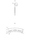
- the rolling bearing shown in FIG. 1 is a self-aligning roller bearing.
- This bearing holds and guides an inner ring 11 and an outer ring 12 that are coaxially arranged inside and outside, a large number of rollers 13 arranged in two rows between the inner and outer races, and the rollers 13 at equal intervals in the circumferential direction.
- a bearing body is constituted by the cage 14.
- a sealed self-aligning roller bearing is constituted by the bearing body and a pair of transparent sealing plates 15 attached to the left and right sides of the inner and outer rings 11 and 12.
- the size of the bearing body excluding the sealing plate 15 is the same as that of a non-sealing self-aligning roller bearing, that is, a self-aligning roller bearing of a type that does not use a sealing plate.
- an outer ring raceway 16 made of a concave spherical surface centered on the bearing center is formed. Further, inner ring raceways 17, 17 composed of two rows of concave spherical surfaces facing the outer ring raceway 16 are provided on the outer diameter surface of the inner ring 11. A flat portion 18 having a slight width rising from both inner ring raceways 17 and 17 along the spherical surface is formed between the inner peripheral portions of both inner ring raceways 17 and 17.
- the barrel-shaped rollers 13 each having a spherical surface are interposed.
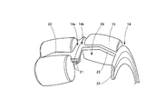
- the cage 14 is a squirrel-cage cage made of a steel plate, and as shown in FIGS. 1 and 3, the left cage 14 a disposed on the outer surface of the left inner ring raceway 17 and the right inner ring raceway 17.
- the right cage 14b disposed on the outer surface of the right and left sides is formed symmetrically.
- Each of the cages 14a and 14b includes an inner ring 21 and an outer ring 22 that face each other in the axial direction, and a column portion 23 that connects the two in the axial direction.
- the column portions 23 are spaced apart from each other in the circumferential direction. Many are provided.
- a rectangular pocket 24 is formed between the pillar portions 23, and one roller 13 is stored and held in each pocket 24.
- the inner peripheral surface of the outer ring 22 is brought into contact with the inner ring raceway 17 (see FIG. 1). By this contact, the cage 14 becomes an inner ring guide type guided by the inner ring 11.
- the outer ring 22 is provided so as to be in contact with the inner ring raceway 17, so that the outer ring 22 closes about half between the inner and outer rings 11 and 12. For this reason, in order to seal the bearing, the other half open portion may be closed by the sealing plate 15.
- the sealing plate 15 of the embodiment is an annular transparent plate made of synthetic resin such as PET, and a closing portion a (see FIG. 2) that closes the open portion is formed along the outer peripheral edge, and an outer ring is formed inside the closing portion.
- 22 is an annular member in which a reinforcing part c is provided inside the adhesive part b and the adhesive part b.
- the reinforced portion c is increased in width to increase the strength of the sealing plate 15 and facilitate handling.
- the sealing plate 15 is attached by bonding the bonding portion b to the outer surface of the outer ring 22.
- the outer peripheral edge of the closed portion a is positioned with respect to the outer ring raceway 16 in a non-contact state with a slight gap that does not lose the sealing performance.
- a contact type may be employ
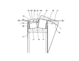
- the assembly of the inner ring 11, the roller 13 and the cage 14 is aligned in the opposite direction with respect to the outer ring 12 in order to check the inside of the bearing.
- the roller 13 is deformed to be exposed, that is, so-called “abdomen” is performed.
- the outer peripheral edge of the sealing plate 15 is on the extension line of the arc of the outer ring raceway 16 (see the one-dot chain line in FIG. 1) or on the outer ring 12 side in the cross section including the axis of the outer ring 12. In this case, since the sealing plate 15 interferes with the outer ring 12, the stomach cannot be laid out.
- the outer peripheral edge of the sealing plate 15 is predetermined on the axial side from the extension line of the arc of the outer ring raceway 16 in the cross section including the axis of the outer ring 12 (see the one-dot chain line in FIG. 4).
- the gap “a” By providing the gap “a”, the above-described interference can be avoided and the abdomen can be raised.
- the gap a By setting the gap a to a minimum size that does not impair sealing, sealing performance can be maintained.
- the outer surface of the sealing plate 15 is colored along the blocking portion a over the portion corresponding to the bonding portion b or both the bonding portion b and the reinforcing portion c.
- a sample seal 25 is adhered.
- Each color sample seal 25 is provided with a rank display such as A, B, C, etc., which indicates the degradation state of the lubricant according to the rank according to the color density of the lubricant.
- symbol 26 shows the injection hole of a lubricant.
- the sealed self-aligning roller bearing of the embodiment is as described above, and is used in the same manner as in the prior art, and the relative alignment at the bearing center between the shaft on the inner ring 11 side and the housing on the outer ring 12 side is performed. Allow. Intrusion of foreign matter from the outside is prevented by the closing plate 15 and the outer ring 22 of the retainer 14, and at the same time, leakage of the lubricant is prevented.
- the lubricant fills the inside of the bearing, and a part of the lubricant comes into contact with the inner surface of the closed portion a of the sealing plate 15.
- the internal lubricant can be visually observed from the outside through the blocking portion a.
- the rank of the deterioration state of the lubricant can be determined.
- this invention can be applied not only to a general roller bearing without self-alignment but also to a rolling bearing such as a ball bearing.
Abstract
A sealed rolling bearing configured in such a manner that, by configuring sealing plates so that the sealing plates require substantially no mounting space in the sealed rolling bearing, the sealed rolling bearing has a size which allows the sealed rolling bearing to be interchangeable with a non-sealed rolling bearing and that the color of the lubricating agent can be visually observed from the outside of the sealed rolling bearing. A sealed rolling bearing is provided with: a rolling bearing body; and sealing members each provided between outer ends of the inner ring raceway (17) and the outer ring raceway (16) of the rolling bearing body. The sealing members consist of transparent plastic sealing plates (15) and are mounted to the retainer (14).
Description
この発明は、異物の浸入防止機能を備えた密封型転がり軸受に関するものである。
This invention relates to a sealed type rolling bearing having a function of preventing entry of foreign matter.
密封型の転がり軸受は、転動体を挟んで内外に対向した内輪と外輪のいずれか一方の軌道輪の軌道の両側に密封板を圧入固定し、他方の軌道輪の軌道の両側に各密封板の自由端部を接触させるか又は接近させる構成がとられる(特許文献1)。密封板は、軸受内部に外部からの異物の浸入を防止する機能のほかに、内部の潤滑剤が外部に漏出することを防止する機能をも有している。
Sealed rolling bearings have a sealing plate that is press-fitted on both sides of the raceway of one of the inner and outer races facing the inside and outside of the rolling element, and each seal plate is placed on both sides of the raceway of the other raceway. The structure which makes the free end part contact or approach is taken (patent document 1). The sealing plate has a function of preventing the internal lubricant from leaking outside, in addition to the function of preventing the entry of foreign matter from the outside into the bearing.
密封板の自由端部を相手軌道輪に接触させるタイプの密封板においては、芯金付きのゴムシールが用いられる。また、非接触タイプの密封板においては、金属板が使用される。
A rubber seal with a cored bar is used for the type of sealing plate in which the free end of the sealing plate is brought into contact with the mating raceway. In the non-contact type sealing plate, a metal plate is used.
いずれのタイプにおいても、内外輪の軌道の両側に密封板の取り付けスペースが必要となるため、内外輪の幅がその取り付けスペースの分だけ大きくなり、非密封型の通常の転がり軸受(特許文献2)と比べると、軸受サイズが大きくなる。このため、非密封型の転がり軸受との部品の互換性が損なわれ、また重量も大となる問題がある。
In both types, since a space for mounting the sealing plate is required on both sides of the raceway of the inner and outer rings, the width of the inner and outer rings is increased by the amount of the mounting space, and a non-sealed normal rolling bearing (Patent Document 2) ), The bearing size becomes larger. For this reason, there is a problem that compatibility of parts with the non-sealing type rolling bearing is lost and the weight is increased.
密封板の取り付けスペースを少なくするために、密封板を保持器にねじ止めした転がり軸受が知られている(特許文献3)。この転がり軸受に係る発明は、密封板を外輪の内径面又は内輪の外径面に圧入する際に、密封板又は内外輪が変形するおそれをなくすことを発明の目的としている。そのために、密封板を軸受の保持器にねじ止めにより取り付け、その密封板の内外周縁を外輪内径面及び内輪外径面に接触又は接近させる構成を採っている。
In order to reduce the mounting space for the sealing plate, a rolling bearing in which the sealing plate is screwed to a cage is known (Patent Document 3). An object of the invention related to the rolling bearing is to eliminate the possibility of deformation of the sealing plate or the inner and outer rings when the sealing plate is press-fitted into the inner diameter surface of the outer ring or the outer diameter surface of the inner ring. For this purpose, the sealing plate is attached to the bearing retainer by screwing, and the inner and outer peripheral edges of the sealing plate are brought into contact with or close to the outer ring inner diameter surface and the inner ring outer diameter surface.
一方、密封型の転がり軸受においては、内部に封止された潤滑剤が使用期間の経過とともに潤滑機能が劣化するため、定期的な点検や潤滑剤の交換が必要である。その場合の潤滑剤の劣化状況の簡便な判定方法として、潤滑剤の色を目視により観察し、色見本と比べることによって判定する方法がある。
On the other hand, in a sealed type rolling bearing, since the lubrication function of the lubricant sealed inside deteriorates with the passage of the service period, periodic inspection and replacement of the lubricant are necessary. As a simple determination method of the deterioration state of the lubricant in that case, there is a method of determining by visually observing the color of the lubricant and comparing it with a color sample.
しかし、特許文献3に開示された密封型転がり軸受をはじめ、その他の従来の密封型転がり軸受においては、その密封板が金属板やゴム等の不透明な材料で形成されているため、軸受の外部から潤滑剤の色を目視により観察することは不可能である。このため、潤滑剤の劣化状況の判定に際しては、軸受を取り外し、さらにこれを分解して内部の潤滑剤の色を観察するという手数を要する問題がある。
However, in other sealed type rolling bearings including the sealed type rolling bearing disclosed in Patent Document 3, since the sealed plate is formed of an opaque material such as a metal plate or rubber, the outside of the bearing Therefore, it is impossible to visually observe the color of the lubricant. For this reason, when determining the deterioration state of the lubricant, there is a problem that it takes time and effort to remove the bearing, further disassemble it and observe the color of the lubricant inside.
そこで、この発明は、密封型転がり軸受における密封板の取り付けスペースを実質的にゼロとすることにより、軸受サイズを非密封型の転がり軸受との部品の互換性を持たせ、かつ軸受の外部から潤滑剤の色を目視により観察することができるようにした密封型転がり軸受を提供することを課題とする。
Therefore, the present invention makes the bearing size compatible with the non-sealed type rolling bearing by reducing the mounting space of the sealing plate in the sealed type rolling bearing to substantially zero, and from the outside of the bearing. It is an object of the present invention to provide a hermetic rolling bearing capable of visually observing the color of a lubricant.
前記の課題を解決するために、この発明は、内輪と外輪、これらの内輪軌道と外輪軌道の間に介在された多数の転動体、前記転動体の保持器からなる転がり軸受本体と、前記転がり軸受本体の内輪軌道と外輪軌道の外端部間に設けられた密封部材とからなる密封型転がり軸受において、前記密封部材が透明なプラスチック製の密封板により形成され前記保持器に取り付けられた構成を採用したものである。
In order to solve the above-described problems, the present invention includes an inner ring and an outer ring, a large number of rolling elements interposed between the inner ring raceway and the outer ring raceway, a rolling bearing body including a holder for the rolling element, and the rolling In a sealing type rolling bearing comprising an inner ring raceway of a bearing body and a sealing member provided between outer end portions of an outer ring raceway, the sealing member is formed of a transparent plastic sealing plate and attached to the cage Is adopted.
前記密封板の一部に潤滑剤の劣化状況を示す色見本シールが接着された構成を採ることもできる。
It is also possible to adopt a configuration in which a color sample seal indicating the state of deterioration of the lubricant is adhered to a part of the sealing plate.
この発明によれば、密封板を保持器に取り付けることにより、内外輪の軌道溝の両側に密封板の取り付けスペースが実質的にゼロになるので、軸受サイズを非密封型のものと同一に形成することができ、これにより部品の互換性を有する。これと同時に、前記の密封板の内側に接した潤滑剤の濃度を外部から目視できるので、迅速に潤滑剤の劣化状況を判定できる効果も発揮する。
According to the present invention, by attaching the sealing plate to the cage, the mounting space for the sealing plate is substantially zero on both sides of the raceway grooves of the inner and outer rings, so the bearing size is made the same as that of the non-sealing type. Thereby having component compatibility. At the same time, since the concentration of the lubricant in contact with the inside of the sealing plate can be visually observed from the outside, an effect of quickly determining the deterioration state of the lubricant is also exhibited.
さらに、密封板は、1枚の透明合成樹脂板によって形成されるので、従来のゴムや金属板によるものに比べ、軽量かつ低コストである利点もある。
Furthermore, since the sealing plate is formed of a single transparent synthetic resin plate, there is an advantage that it is lighter and lower in cost than those using conventional rubber or metal plates.
なお、前記密封板の一部に潤滑剤の劣化状況を示す色見本シールを接着しておくことにより、前記の判定を一層迅速に行うことができる。
It should be noted that the above determination can be made more quickly by adhering a color sample seal indicating the deterioration state of the lubricant to a part of the sealing plate.
以下、この発明の実施の形態を添付図面に基づいて説明する。図1に示した転がり軸受は、自動調心ころ軸受である。この軸受は、同軸状態に内外に配置された内輪11、外輪12、これら内外の軌道輪の間に2列に配置された多数のころ13、前記ころ13を周方向に等間隔に保持・案内する保持器14により軸受本体が構成される。
Hereinafter, embodiments of the present invention will be described with reference to the accompanying drawings. The rolling bearing shown in FIG. 1 is a self-aligning roller bearing. This bearing holds and guides an inner ring 11 and an outer ring 12 that are coaxially arranged inside and outside, a large number of rollers 13 arranged in two rows between the inner and outer races, and the rollers 13 at equal intervals in the circumferential direction. A bearing body is constituted by the cage 14.
前記の軸受本体と、その内外輪11、12の左右に取り付けられた一対の透明な密封板15とによって密封型の自動調心ころ軸受が構成される。
A sealed self-aligning roller bearing is constituted by the bearing body and a pair of transparent sealing plates 15 attached to the left and right sides of the inner and outer rings 11 and 12.
前記の密封板15を除いた軸受本体のサイズは、非密封型の自動調心ころ軸受、即ち、密封板を使用しない形式の自動調心ころ軸受と同じサイズに形成される。
The size of the bearing body excluding the sealing plate 15 is the same as that of a non-sealing self-aligning roller bearing, that is, a self-aligning roller bearing of a type that does not use a sealing plate.
前記外輪12の内径面には、軸受中心に中心をもった凹球面からなる外輪軌道16が形成される。また、前記の内輪11の外径面には前記外輪軌道16に対向した2列の凹球面からなる内輪軌道17、17が設けられる。両方の内輪軌道17、17の内周部の間に両方の内輪軌道17、17からその球面に沿って立ち上がった僅かな幅の平坦部18が形成される。
On the inner diameter surface of the outer ring 12, an outer ring raceway 16 made of a concave spherical surface centered on the bearing center is formed. Further, inner ring raceways 17, 17 composed of two rows of concave spherical surfaces facing the outer ring raceway 16 are provided on the outer diameter surface of the inner ring 11. A flat portion 18 having a slight width rising from both inner ring raceways 17 and 17 along the spherical surface is formed between the inner peripheral portions of both inner ring raceways 17 and 17.
前記の各内輪軌道17と外輪軌道16との間に、それぞれ球面を持った樽形のころ13が介在される。
Between the inner ring raceway 17 and the outer ring raceway 16, the barrel-shaped rollers 13 each having a spherical surface are interposed.
保持器14は、鋼板打ち抜き製のかご形保持器であり、図1及び図3に示したように、左側の内輪軌道17の外側面に配置される左保持器14aと、右側の内輪軌道17の外側面に配置される右保持器14bが左右対称形に形成されたものである。各保持器14a、14bは、いずれも軸方向に対向した内側環21と外側環22及びこれらの間を軸方向に連結する柱部23とからなり、柱部23は周方向に一定間隔をおいて多数設けられる。柱部23相互間に四角形のポケット24が形成され、各ポケット24にころ13が1個ずつ収納保持される。
The cage 14 is a squirrel-cage cage made of a steel plate, and as shown in FIGS. 1 and 3, the left cage 14 a disposed on the outer surface of the left inner ring raceway 17 and the right inner ring raceway 17. The right cage 14b disposed on the outer surface of the right and left sides is formed symmetrically. Each of the cages 14a and 14b includes an inner ring 21 and an outer ring 22 that face each other in the axial direction, and a column portion 23 that connects the two in the axial direction. The column portions 23 are spaced apart from each other in the circumferential direction. Many are provided. A rectangular pocket 24 is formed between the pillar portions 23, and one roller 13 is stored and held in each pocket 24.
前記外側環22の内周面が内輪軌道17に接触される(図1参照)。この接触により保持器14は内輪11によって案内される内輪案内型となる。
The inner peripheral surface of the outer ring 22 is brought into contact with the inner ring raceway 17 (see FIG. 1). By this contact, the cage 14 becomes an inner ring guide type guided by the inner ring 11.
外側環22が、内輪軌道17に接触するように設けられることにより、外側環22は内外輪11、12の間の約半分を閉塞する。このため、この軸受を密封するためには、残りの半分弱の開放部分を前記の密封板15によって閉塞すればよい。
The outer ring 22 is provided so as to be in contact with the inner ring raceway 17, so that the outer ring 22 closes about half between the inner and outer rings 11 and 12. For this reason, in order to seal the bearing, the other half open portion may be closed by the sealing plate 15.
実施形態の密封板15は、PET等の合成樹脂製の環状透明板であり、前記の開放部分を閉塞する閉塞部a(図2参照)が外周縁に沿って形成され、その内側に外側環22に対する接着部b及び接着部bの内側に補強部cを設けた環状の部材である。補強部cは、その分だけ幅を大きくすることにより、密封板15の強度を高め、取扱い易くしたものである。
The sealing plate 15 of the embodiment is an annular transparent plate made of synthetic resin such as PET, and a closing portion a (see FIG. 2) that closes the open portion is formed along the outer peripheral edge, and an outer ring is formed inside the closing portion. 22 is an annular member in which a reinforcing part c is provided inside the adhesive part b and the adhesive part b. The reinforced portion c is increased in width to increase the strength of the sealing plate 15 and facilitate handling.
前記密封板15は、接着部bを外側環22の外側面に接着することにより取り付けられる。閉塞部aの外周縁は外輪軌道16に対し、密封性を失わない僅かな隙間をもった非接触状態に位置決めされる。
なお、閉塞部aは前記のように、非接触(すきま有)を基本とするが、防塵性及び密封性を高めるため接触タイプを採用する場合がある。 Thesealing plate 15 is attached by bonding the bonding portion b to the outer surface of the outer ring 22. The outer peripheral edge of the closed portion a is positioned with respect to the outer ring raceway 16 in a non-contact state with a slight gap that does not lose the sealing performance.
In addition, as above-mentioned, although the obstruction | occlusion part a is based on non-contact (with clearance), a contact type may be employ | adopted in order to improve dust resistance and sealing performance.
なお、閉塞部aは前記のように、非接触(すきま有)を基本とするが、防塵性及び密封性を高めるため接触タイプを採用する場合がある。 The
In addition, as above-mentioned, although the obstruction | occlusion part a is based on non-contact (with clearance), a contact type may be employ | adopted in order to improve dust resistance and sealing performance.
自動調心ころ軸受においては、図4に示したように、軸受内部の点検等のために、外輪12に対し、内輪11、ころ13及び保持器14のアセンブリが相対的に反対方向に調心することによってころ13が露出した状態に変形すること、いわゆる「腹出し」が行われる場合がある。
In the self-aligning roller bearing, as shown in FIG. 4, the assembly of the inner ring 11, the roller 13 and the cage 14 is aligned in the opposite direction with respect to the outer ring 12 in order to check the inside of the bearing. By doing so, there is a case where the roller 13 is deformed to be exposed, that is, so-called “abdomen” is performed.
図1に示したように、前記密封板15の外周縁が、前記外輪12の軸線を含む断面内における外輪軌道16の円弧の延長線(図1の一点鎖線参照)上又は外輪12側にある場合は、密封板15が外輪12に干渉するため、腹出しを行うことはできない。
As shown in FIG. 1, the outer peripheral edge of the sealing plate 15 is on the extension line of the arc of the outer ring raceway 16 (see the one-dot chain line in FIG. 1) or on the outer ring 12 side in the cross section including the axis of the outer ring 12. In this case, since the sealing plate 15 interferes with the outer ring 12, the stomach cannot be laid out.
しかし、図4に示したように、密封板15の外周縁が、前記外輪12の軸線を含む断面内における外輪軌道16の円弧の延長線(図4の一点鎖線参照)より軸側に所定の隙間aを設けることにより、前記の干渉を回避して腹出しが可能となる。前記隙間aを密封の損なわない最小の大きさに設定することにより、密封性を維持することができる。
However, as shown in FIG. 4, the outer peripheral edge of the sealing plate 15 is predetermined on the axial side from the extension line of the arc of the outer ring raceway 16 in the cross section including the axis of the outer ring 12 (see the one-dot chain line in FIG. 4). By providing the gap “a”, the above-described interference can be avoided and the abdomen can be raised. By setting the gap a to a minimum size that does not impair sealing, sealing performance can be maintained.
前記の密封板15の外表面には、図2(b)に示したように、接着部bに相当する部分又は接着部bと補強部cの両方の部分にわたり、閉塞部aに沿って色見本シール25が接着されている。各色見本シール25には、潤滑剤の色の濃度に応じて潤滑剤の劣化状況をランク分けして示すA、B、Cなどのランク分け表示が付される。その他、図1において符号26は潤滑剤の注入穴を示す。
As shown in FIG. 2B, the outer surface of the sealing plate 15 is colored along the blocking portion a over the portion corresponding to the bonding portion b or both the bonding portion b and the reinforcing portion c. A sample seal 25 is adhered. Each color sample seal 25 is provided with a rank display such as A, B, C, etc., which indicates the degradation state of the lubricant according to the rank according to the color density of the lubricant. In addition, in FIG. 1, the code | symbol 26 shows the injection hole of a lubricant.
実施形態の密封型自動調心ころ軸受は以上のようなものであり、従来の場合と同様に使用され、内輪11側の軸と外輪12側のハウジングとの軸受中心における相対的な調心を許容する。外部からの異物の浸入に対しては、閉塞板15と、その保持器14の外側環22によって防止され、同時に潤滑剤の漏出も防止される。
The sealed self-aligning roller bearing of the embodiment is as described above, and is used in the same manner as in the prior art, and the relative alignment at the bearing center between the shaft on the inner ring 11 side and the housing on the outer ring 12 side is performed. Allow. Intrusion of foreign matter from the outside is prevented by the closing plate 15 and the outer ring 22 of the retainer 14, and at the same time, leakage of the lubricant is prevented.
使用中、潤滑剤は軸受内部に充満するので、その一部が密封板15の閉塞部aの内面に接触する。潤滑剤の劣化状況を判定する場合は、外部から閉塞部aを通して内部の潤滑剤を目視することができる。その色と色見本シール25に表示された潤滑剤の色の濃度を比較対照することにより、潤滑剤の劣化状況のランクを判定することができる。
During use, the lubricant fills the inside of the bearing, and a part of the lubricant comes into contact with the inner surface of the closed portion a of the sealing plate 15. When determining the deterioration state of the lubricant, the internal lubricant can be visually observed from the outside through the blocking portion a. By comparing and comparing the color and the density of the lubricant color displayed on the color sample seal 25, the rank of the deterioration state of the lubricant can be determined.
なお、以上の実施形態は、自動調心ころ軸受について述べたが、この発明は、自動調心性のない一般のころ軸受のほか、玉軸受等、転がり軸受一般に適用することができる。
In addition, although the above embodiment described the self-aligning roller bearing, this invention can be applied not only to a general roller bearing without self-alignment but also to a rolling bearing such as a ball bearing.
11 内輪
12 外輪
13 ころ
14 保持器
14a 左保持器
14b 右保持器
15 密封板
16 外輪軌道
17 内輪軌道
18 平坦部
21 内側環
22 外側環
23 柱部
24 ポケット
25 色見本シール
26 注入穴 11Inner ring 12 Outer ring 13 Roller 14 Retainer 14a Left retainer 14b Right retainer 15 Sealing plate 16 Outer ring race 17 Inner ring race 18 Flat part 21 Inner ring 22 Outer ring 23 Pillar part 24 Pocket 25 Color sample seal 26 Injection hole
12 外輪
13 ころ
14 保持器
14a 左保持器
14b 右保持器
15 密封板
16 外輪軌道
17 内輪軌道
18 平坦部
21 内側環
22 外側環
23 柱部
24 ポケット
25 色見本シール
26 注入穴 11
Claims (10)
- 内輪と外輪、これらの内輪軌道と外輪軌道の間に介在された多数の転動体、前記転動体の保持器からなる転がり軸受本体と、前記転がり軸受本体の内輪軌道と外輪軌道の外端部間に設けられた密封部材とからなる密封型転がり軸受において、前記密封部材が透明なプラスチック製の密封板により形成され、前記保持器に取り付けられたことを特徴とする密封型転がり軸受。 An inner ring and an outer ring, a large number of rolling elements interposed between the inner ring raceway and the outer ring raceway, a rolling bearing body composed of a cage for the rolling element, and between the inner ring raceway of the rolling bearing body and the outer end of the outer ring raceway. A sealing type rolling bearing comprising a sealing member provided on the sealing member, wherein the sealing member is formed of a transparent plastic sealing plate and attached to the cage.
- 前記転がり軸受本体が、非密封型の転がり軸受と同一サイズをもって構成され、両者の構成部材に互換性があることを特徴とする請求項1に記載の密封型転がり軸受。 2. The sealed type rolling bearing according to claim 1, wherein the rolling bearing body has the same size as that of the non-sealed type rolling bearing, and both constituent members are compatible.
- 前記保持器が、軸方向に対向した一対の側環と、これらの側環の間に周方向に一定ピッチで設けられた多数の柱部からなり、各柱部相互間に転動体を収納する多数のポケットが形成されたかご形保持器であり、前記側環が前記内輪に接触することにより当該保持器が内輪案内型となっていることを特徴とする請求項1又は2に記載の密封型転がり軸受。 The cage is composed of a pair of side rings opposed in the axial direction and a large number of column parts provided at a constant pitch in the circumferential direction between the side rings, and accommodates rolling elements between the column parts. The hermetically sealed cage according to claim 1 or 2, wherein the cage is a cage-type cage in which a large number of pockets are formed, and the cage is of an inner ring guide type when the side ring contacts the inner ring. Type rolling bearing.
- 前記密封板が、前記保持器の側環に接合されたことを特徴とする請求項3に記載の密封型転がり軸受。 The sealed rolling bearing according to claim 3, wherein the sealing plate is joined to a side ring of the cage.
- 前記密封板が前記保持器の側環と外輪軌道の間の隙間を閉塞することにより、当該側環と密封板の両者の協働によって前記内輪軌道と外輪軌道の間を密封することを特徴とする請求項3又は4に記載の密封型転がり軸受。 The sealing plate seals a gap between the inner ring raceway and the outer ring raceway by the cooperation of both the side ring and the seal plate by closing a gap between the side ring of the cage and the outer raceway. The sealed rolling bearing according to claim 3 or 4.
- 前記密封板が、外周縁に沿ってその内径側に設けられた閉塞部、前記閉塞部に沿ってその内径側に設けられた接着部、及び前記接着部に沿ってその内径側に設けられた補強部の3つの周方向のゾーンを有することを特徴とする請求項1から5のいずれかに記載の密封型転がり軸受。 The sealing plate is provided on the inner diameter side along the outer peripheral edge, on the inner diameter side along the adhesion portion, and on the inner diameter side along the adhesion portion. The sealed rolling bearing according to any one of claims 1 to 5, comprising three circumferential zones of the reinforcing portion.
- 前記密封板の一部に潤滑剤の劣化状況を示す色見本シールが接着されたことを特徴とする請求項1から6のいずれかに記載の密封型転がり軸受。 The sealed rolling bearing according to any one of claims 1 to 6, wherein a color sample seal indicating a deterioration state of the lubricant is adhered to a part of the sealing plate.
- 前記色見本シールが、前記密封板の接着部外面に接着されたことを特徴とする請求項7に記載の密封型転がり軸受。 The sealed type rolling bearing according to claim 7, wherein the color sample seal is bonded to an outer surface of the bonded portion of the sealing plate.
- 前記転がり軸受本体が自動調心ころ軸受により構成され、前記密封板の外周縁が、前記外輪の軸線を含む断面内における外輪軌道の円弧の延長線より軸側にあることを特徴とする請求項1から8のいずれかに記載の密封型転がり軸受。 The rolling bearing main body is constituted by a self-aligning roller bearing, and an outer peripheral edge of the sealing plate is located on an axial side with respect to an arc extension line of an outer ring raceway in a cross section including an axis of the outer ring. The sealed rolling bearing according to any one of 1 to 8.
- 前記転がり軸受本体が、自動調心ころ軸受、その他の転がり軸受であることを特徴とする請求項9に記載の密封型転がり軸受。 10. The sealed rolling bearing according to claim 9, wherein the rolling bearing body is a self-aligning roller bearing or other rolling bearing.
Priority Applications (2)
| Application Number | Priority Date | Filing Date | Title |
|---|---|---|---|
| US13/394,224 US20120163745A1 (en) | 2009-09-07 | 2010-08-13 | Sealed rolling bearing |
| EP10813613A EP2476926A1 (en) | 2009-09-07 | 2010-08-13 | Sealed rolling bearing |
Applications Claiming Priority (2)
| Application Number | Priority Date | Filing Date | Title |
|---|---|---|---|
| JP2009205394A JP2011058508A (en) | 2009-09-07 | 2009-09-07 | Sealed rolling bearing |
| JP2009-205394 | 2009-09-07 |
Publications (1)
| Publication Number | Publication Date |
|---|---|
| WO2011027662A1 true WO2011027662A1 (en) | 2011-03-10 |
Family
ID=43649204
Family Applications (1)
| Application Number | Title | Priority Date | Filing Date |
|---|---|---|---|
| PCT/JP2010/063739 WO2011027662A1 (en) | 2009-09-07 | 2010-08-13 | Sealed rolling bearing |
Country Status (4)
| Country | Link |
|---|---|
| US (1) | US20120163745A1 (en) |
| EP (1) | EP2476926A1 (en) |
| JP (1) | JP2011058508A (en) |
| WO (1) | WO2011027662A1 (en) |
Cited By (4)
| Publication number | Priority date | Publication date | Assignee | Title |
|---|---|---|---|---|
| EP2808570A1 (en) | 2013-05-31 | 2014-12-03 | NTN-SNR Roulements | Bearing provided with a sealing system |
| US20150176652A1 (en) * | 2013-12-19 | 2015-06-25 | Aktiebolaget Skf | Rolling-element bearing including seal unit |
| EP3029344A1 (en) | 2014-12-01 | 2016-06-08 | NTN-SNR Roulements | Sealing and sealing system for bearings and bearing equipped with such sealings and sealing systems |
| DE102017116875A1 (en) * | 2017-07-26 | 2019-01-31 | Thyssenkrupp Ag | Combination of a roller bearing and at least one cover element and roller mill |
Families Citing this family (8)
| Publication number | Priority date | Publication date | Assignee | Title |
|---|---|---|---|---|
| US9964150B2 (en) * | 2012-10-04 | 2018-05-08 | Aktiebolaget Skf | Method for lubricating a rolling element bearing |
| WO2014054993A1 (en) * | 2012-10-04 | 2014-04-10 | Aktiebolaget Skf | Bearing cage & rolling element bearing |
| JP2015530549A (en) * | 2012-10-04 | 2015-10-15 | アクティエボラゲット・エスコーエッフ | Cage and rolling bearing |
| CN111701248A (en) * | 2014-07-09 | 2020-09-25 | H·迈尔 | Inhabitable supporting structure for viewing ferris wheel |
| US10082179B2 (en) | 2014-12-16 | 2018-09-25 | Roller Bearing Company Of America, Inc. | Seal for self aligning roller bearing |
| JP2016161037A (en) * | 2015-03-02 | 2016-09-05 | Ntn株式会社 | Self-aligning roller bearing |
| FR3052831B1 (en) * | 2016-06-20 | 2018-07-27 | Ntn-Snr Roulements | METHOD FOR SEALING A BEARING BEARING AND BEARING BEARING THUS OBTAINED |
| JP2019215058A (en) * | 2018-06-14 | 2019-12-19 | Ntn株式会社 | Self-aligning roller bearing |
Citations (5)
| Publication number | Priority date | Publication date | Assignee | Title |
|---|---|---|---|---|
| JPH0712736Y2 (en) | 1987-11-10 | 1995-03-29 | 日本精工株式会社 | Spherical roller bearing |
| JPH09317760A (en) | 1996-05-30 | 1997-12-09 | Ntn Corp | Self-aligning roller bearing |
| JP2003161318A (en) * | 2001-07-10 | 2003-06-06 | Nsk Ltd | Bearing unit |
| JP2003202023A (en) * | 2002-01-08 | 2003-07-18 | Nsk Ltd | Ball bearing and bearing device |
| JP2007198540A (en) | 2006-01-27 | 2007-08-09 | Nsk Ltd | Roller bearing with seal |
Family Cites Families (6)
| Publication number | Priority date | Publication date | Assignee | Title |
|---|---|---|---|---|
| US3981550A (en) * | 1975-01-20 | 1976-09-21 | Borg-Warner Corporation | Bearing improvement |
| JPS6363967A (en) * | 1986-09-05 | 1988-03-22 | Toshiba Corp | Method for judging deterioration of lubricating oil |
| JPH01141231A (en) * | 1987-11-24 | 1989-06-02 | Nec Corp | Bearing |
| DE8904504U1 (en) * | 1989-04-11 | 1989-05-18 | Fag Kugelfischer Georg Schaefer Kgaa, 8720 Schweinfurt, De | |
| JP3477835B2 (en) * | 1993-10-12 | 2003-12-10 | 日本精工株式会社 | Spherical roller bearing with cage |
| JP2006177715A (en) * | 2004-12-21 | 2006-07-06 | Jtekt Corp | Lubricant monitoring device |
-
2009
- 2009-09-07 JP JP2009205394A patent/JP2011058508A/en not_active Withdrawn
-
2010
- 2010-08-13 WO PCT/JP2010/063739 patent/WO2011027662A1/en active Application Filing
- 2010-08-13 EP EP10813613A patent/EP2476926A1/en not_active Withdrawn
- 2010-08-13 US US13/394,224 patent/US20120163745A1/en not_active Abandoned
Patent Citations (5)
| Publication number | Priority date | Publication date | Assignee | Title |
|---|---|---|---|---|
| JPH0712736Y2 (en) | 1987-11-10 | 1995-03-29 | 日本精工株式会社 | Spherical roller bearing |
| JPH09317760A (en) | 1996-05-30 | 1997-12-09 | Ntn Corp | Self-aligning roller bearing |
| JP2003161318A (en) * | 2001-07-10 | 2003-06-06 | Nsk Ltd | Bearing unit |
| JP2003202023A (en) * | 2002-01-08 | 2003-07-18 | Nsk Ltd | Ball bearing and bearing device |
| JP2007198540A (en) | 2006-01-27 | 2007-08-09 | Nsk Ltd | Roller bearing with seal |
Cited By (5)
| Publication number | Priority date | Publication date | Assignee | Title |
|---|---|---|---|---|
| EP2808570A1 (en) | 2013-05-31 | 2014-12-03 | NTN-SNR Roulements | Bearing provided with a sealing system |
| US20150176652A1 (en) * | 2013-12-19 | 2015-06-25 | Aktiebolaget Skf | Rolling-element bearing including seal unit |
| US9739313B2 (en) * | 2013-12-19 | 2017-08-22 | Aktiebolaget Skf | Rolling-element bearing including seal unit |
| EP3029344A1 (en) | 2014-12-01 | 2016-06-08 | NTN-SNR Roulements | Sealing and sealing system for bearings and bearing equipped with such sealings and sealing systems |
| DE102017116875A1 (en) * | 2017-07-26 | 2019-01-31 | Thyssenkrupp Ag | Combination of a roller bearing and at least one cover element and roller mill |
Also Published As
| Publication number | Publication date |
|---|---|
| EP2476926A1 (en) | 2012-07-18 |
| JP2011058508A (en) | 2011-03-24 |
| US20120163745A1 (en) | 2012-06-28 |
Similar Documents
| Publication | Publication Date | Title |
|---|---|---|
| WO2011027662A1 (en) | Sealed rolling bearing | |
| JP4255969B2 (en) | Bearing roller chain | |
| JP2008133871A (en) | Bearing roller chain | |
| JP2007198540A (en) | Roller bearing with seal | |
| WO2016125516A1 (en) | Bearing device for railway vehicle | |
| JP2005076660A (en) | Anti-friction bearing device | |
| US20160017926A1 (en) | Bearing device with sealing device | |
| US9752620B2 (en) | Dynamically aligning, maintenance free, radial insert ball bearing | |
| JP6282609B2 (en) | Rolling bearing | |
| CN109661523B (en) | Axle bearing device | |
| JP2017053368A (en) | Bearing device for wheel | |
| CN111936757B (en) | Bearing device for wheel | |
| JP2005325867A (en) | Bearing for railroad car | |
| JP2005226787A (en) | Sealing device for bearing | |
| JP2007285477A (en) | Seal chain | |
| JP6396681B2 (en) | Wheel bearing device | |
| JP6024291B2 (en) | Rolling bearing | |
| US10323691B2 (en) | Needle bush bearing with sealing device | |
| KR102580857B1 (en) | Rolling bearing having improved sealing function | |
| US11499605B2 (en) | Seal chain | |
| JP2015183712A (en) | bearing device | |
| JP2009287626A (en) | Rolling bearing device | |
| JP6866567B2 (en) | Self-aligning roller bearing | |
| WO2018180290A1 (en) | Conical roller bearing | |
| JP2012241819A (en) | Bearing device for water pump |
Legal Events
| Date | Code | Title | Description |
|---|---|---|---|
| 121 | Ep: the epo has been informed by wipo that ep was designated in this application |
Ref document number: 10813613 Country of ref document: EP Kind code of ref document: A1 |
|
| WWE | Wipo information: entry into national phase |
Ref document number: 13394224 Country of ref document: US |
|
| WWE | Wipo information: entry into national phase |
Ref document number: 2010813613 Country of ref document: EP |
|
| NENP | Non-entry into the national phase |
Ref country code: DE |