WO2011019091A1 - 呼吸波形情報の演算装置及び呼吸波形情報を利用した医療機器 - Google Patents
呼吸波形情報の演算装置及び呼吸波形情報を利用した医療機器 Download PDFInfo
- Publication number
- WO2011019091A1 WO2011019091A1 PCT/JP2010/063892 JP2010063892W WO2011019091A1 WO 2011019091 A1 WO2011019091 A1 WO 2011019091A1 JP 2010063892 W JP2010063892 W JP 2010063892W WO 2011019091 A1 WO2011019091 A1 WO 2011019091A1
- Authority
- WO
- WIPO (PCT)
- Prior art keywords
- respiratory
- waveform
- information
- sleep
- time
- Prior art date
Links
Images


Classifications
-
- A—HUMAN NECESSITIES
- A61—MEDICAL OR VETERINARY SCIENCE; HYGIENE
- A61M—DEVICES FOR INTRODUCING MEDIA INTO, OR ONTO, THE BODY; DEVICES FOR TRANSDUCING BODY MEDIA OR FOR TAKING MEDIA FROM THE BODY; DEVICES FOR PRODUCING OR ENDING SLEEP OR STUPOR
- A61M16/00—Devices for influencing the respiratory system of patients by gas treatment, e.g. mouth-to-mouth respiration; Tracheal tubes
-
- A—HUMAN NECESSITIES
- A61—MEDICAL OR VETERINARY SCIENCE; HYGIENE
- A61B—DIAGNOSIS; SURGERY; IDENTIFICATION
- A61B5/00—Measuring for diagnostic purposes; Identification of persons
- A61B5/08—Detecting, measuring or recording devices for evaluating the respiratory organs
- A61B5/0826—Detecting or evaluating apnoea events
-
- A—HUMAN NECESSITIES
- A61—MEDICAL OR VETERINARY SCIENCE; HYGIENE
- A61B—DIAGNOSIS; SURGERY; IDENTIFICATION
- A61B5/00—Measuring for diagnostic purposes; Identification of persons
- A61B5/08—Detecting, measuring or recording devices for evaluating the respiratory organs
- A61B5/0816—Measuring devices for examining respiratory frequency
-
- A—HUMAN NECESSITIES
- A61—MEDICAL OR VETERINARY SCIENCE; HYGIENE
- A61B—DIAGNOSIS; SURGERY; IDENTIFICATION
- A61B5/00—Measuring for diagnostic purposes; Identification of persons
- A61B5/08—Detecting, measuring or recording devices for evaluating the respiratory organs
- A61B5/087—Measuring breath flow
-
- A—HUMAN NECESSITIES
- A61—MEDICAL OR VETERINARY SCIENCE; HYGIENE
- A61B—DIAGNOSIS; SURGERY; IDENTIFICATION
- A61B5/00—Measuring for diagnostic purposes; Identification of persons
- A61B5/103—Detecting, measuring or recording devices for testing the shape, pattern, colour, size or movement of the body or parts thereof, for diagnostic purposes
- A61B5/11—Measuring movement of the entire body or parts thereof, e.g. head or hand tremor, mobility of a limb
- A61B5/113—Measuring movement of the entire body or parts thereof, e.g. head or hand tremor, mobility of a limb occurring during breathing
-
- A—HUMAN NECESSITIES
- A61—MEDICAL OR VETERINARY SCIENCE; HYGIENE
- A61B—DIAGNOSIS; SURGERY; IDENTIFICATION
- A61B5/00—Measuring for diagnostic purposes; Identification of persons
- A61B5/41—Detecting, measuring or recording for evaluating the immune or lymphatic systems
- A61B5/414—Evaluating particular organs or parts of the immune or lymphatic systems
- A61B5/415—Evaluating particular organs or parts of the immune or lymphatic systems the glands, e.g. tonsils, adenoids or thymus
-
- A—HUMAN NECESSITIES
- A61—MEDICAL OR VETERINARY SCIENCE; HYGIENE
- A61B—DIAGNOSIS; SURGERY; IDENTIFICATION
- A61B5/00—Measuring for diagnostic purposes; Identification of persons
- A61B5/48—Other medical applications
- A61B5/4806—Sleep evaluation
- A61B5/4812—Detecting sleep stages or cycles
-
- A—HUMAN NECESSITIES
- A61—MEDICAL OR VETERINARY SCIENCE; HYGIENE
- A61B—DIAGNOSIS; SURGERY; IDENTIFICATION
- A61B5/00—Measuring for diagnostic purposes; Identification of persons
- A61B5/48—Other medical applications
- A61B5/4806—Sleep evaluation
- A61B5/4815—Sleep quality
-
- A—HUMAN NECESSITIES
- A61—MEDICAL OR VETERINARY SCIENCE; HYGIENE
- A61B—DIAGNOSIS; SURGERY; IDENTIFICATION
- A61B5/00—Measuring for diagnostic purposes; Identification of persons
- A61B5/48—Other medical applications
- A61B5/4806—Sleep evaluation
- A61B5/4818—Sleep apnoea
-
- A—HUMAN NECESSITIES
- A61—MEDICAL OR VETERINARY SCIENCE; HYGIENE
- A61B—DIAGNOSIS; SURGERY; IDENTIFICATION
- A61B5/00—Measuring for diagnostic purposes; Identification of persons
- A61B5/72—Signal processing specially adapted for physiological signals or for diagnostic purposes
- A61B5/7235—Details of waveform analysis
- A61B5/7253—Details of waveform analysis characterised by using transforms
- A61B5/7257—Details of waveform analysis characterised by using transforms using Fourier transforms
-
- A—HUMAN NECESSITIES
- A61—MEDICAL OR VETERINARY SCIENCE; HYGIENE
- A61M—DEVICES FOR INTRODUCING MEDIA INTO, OR ONTO, THE BODY; DEVICES FOR TRANSDUCING BODY MEDIA OR FOR TAKING MEDIA FROM THE BODY; DEVICES FOR PRODUCING OR ENDING SLEEP OR STUPOR
- A61M16/00—Devices for influencing the respiratory system of patients by gas treatment, e.g. mouth-to-mouth respiration; Tracheal tubes
- A61M16/021—Devices for influencing the respiratory system of patients by gas treatment, e.g. mouth-to-mouth respiration; Tracheal tubes operated by electrical means
- A61M16/022—Control means therefor
- A61M16/024—Control means therefor including calculation means, e.g. using a processor
- A61M16/026—Control means therefor including calculation means, e.g. using a processor specially adapted for predicting, e.g. for determining an information representative of a flow limitation during a ventilation cycle by using a root square technique or a regression analysis
-
- A—HUMAN NECESSITIES
- A61—MEDICAL OR VETERINARY SCIENCE; HYGIENE
- A61M—DEVICES FOR INTRODUCING MEDIA INTO, OR ONTO, THE BODY; DEVICES FOR TRANSDUCING BODY MEDIA OR FOR TAKING MEDIA FROM THE BODY; DEVICES FOR PRODUCING OR ENDING SLEEP OR STUPOR
- A61M16/00—Devices for influencing the respiratory system of patients by gas treatment, e.g. mouth-to-mouth respiration; Tracheal tubes
- A61M16/10—Preparation of respiratory gases or vapours
- A61M16/1005—Preparation of respiratory gases or vapours with O2 features or with parameter measurement
- A61M16/101—Preparation of respiratory gases or vapours with O2 features or with parameter measurement using an oxygen concentrator
-
- G—PHYSICS
- G16—INFORMATION AND COMMUNICATION TECHNOLOGY [ICT] SPECIALLY ADAPTED FOR SPECIFIC APPLICATION FIELDS
- G16Z—INFORMATION AND COMMUNICATION TECHNOLOGY [ICT] SPECIALLY ADAPTED FOR SPECIFIC APPLICATION FIELDS, NOT OTHERWISE PROVIDED FOR
- G16Z99/00—Subject matter not provided for in other main groups of this subclass
-
- A—HUMAN NECESSITIES
- A61—MEDICAL OR VETERINARY SCIENCE; HYGIENE
- A61M—DEVICES FOR INTRODUCING MEDIA INTO, OR ONTO, THE BODY; DEVICES FOR TRANSDUCING BODY MEDIA OR FOR TAKING MEDIA FROM THE BODY; DEVICES FOR PRODUCING OR ENDING SLEEP OR STUPOR
- A61M16/00—Devices for influencing the respiratory system of patients by gas treatment, e.g. mouth-to-mouth respiration; Tracheal tubes
- A61M16/10—Preparation of respiratory gases or vapours
- A61M16/105—Filters
- A61M16/106—Filters in a path
- A61M16/107—Filters in a path in the inspiratory path
-
- A—HUMAN NECESSITIES
- A61—MEDICAL OR VETERINARY SCIENCE; HYGIENE
- A61M—DEVICES FOR INTRODUCING MEDIA INTO, OR ONTO, THE BODY; DEVICES FOR TRANSDUCING BODY MEDIA OR FOR TAKING MEDIA FROM THE BODY; DEVICES FOR PRODUCING OR ENDING SLEEP OR STUPOR
- A61M16/00—Devices for influencing the respiratory system of patients by gas treatment, e.g. mouth-to-mouth respiration; Tracheal tubes
- A61M16/10—Preparation of respiratory gases or vapours
- A61M16/1005—Preparation of respiratory gases or vapours with O2 features or with parameter measurement
- A61M2016/102—Measuring a parameter of the content of the delivered gas
- A61M2016/1025—Measuring a parameter of the content of the delivered gas the O2 concentration
-
- A—HUMAN NECESSITIES
- A61—MEDICAL OR VETERINARY SCIENCE; HYGIENE
- A61M—DEVICES FOR INTRODUCING MEDIA INTO, OR ONTO, THE BODY; DEVICES FOR TRANSDUCING BODY MEDIA OR FOR TAKING MEDIA FROM THE BODY; DEVICES FOR PRODUCING OR ENDING SLEEP OR STUPOR
- A61M2202/00—Special media to be introduced, removed or treated
- A61M2202/02—Gases
- A61M2202/0208—Oxygen
-
- A—HUMAN NECESSITIES
- A61—MEDICAL OR VETERINARY SCIENCE; HYGIENE
- A61M—DEVICES FOR INTRODUCING MEDIA INTO, OR ONTO, THE BODY; DEVICES FOR TRANSDUCING BODY MEDIA OR FOR TAKING MEDIA FROM THE BODY; DEVICES FOR PRODUCING OR ENDING SLEEP OR STUPOR
- A61M2202/00—Special media to be introduced, removed or treated
- A61M2202/03—Gases in liquid phase, e.g. cryogenic liquids
-
- Y—GENERAL TAGGING OF NEW TECHNOLOGICAL DEVELOPMENTS; GENERAL TAGGING OF CROSS-SECTIONAL TECHNOLOGIES SPANNING OVER SEVERAL SECTIONS OF THE IPC; TECHNICAL SUBJECTS COVERED BY FORMER USPC CROSS-REFERENCE ART COLLECTIONS [XRACs] AND DIGESTS
- Y02—TECHNOLOGIES OR APPLICATIONS FOR MITIGATION OR ADAPTATION AGAINST CLIMATE CHANGE
- Y02A—TECHNOLOGIES FOR ADAPTATION TO CLIMATE CHANGE
- Y02A90/00—Technologies having an indirect contribution to adaptation to climate change
- Y02A90/10—Information and communication technologies [ICT] supporting adaptation to climate change, e.g. for weather forecasting or climate simulation
Definitions
- the present invention relates to an apparatus for calculating respiratory waveform information, an apparatus for evaluating comfort including sleep quality, an apparatus for calculating physiological data, a computer program for performing calculations using respiratory waveform information, and the quality of sleep of a subject.
- Computer program for evaluating the degree of comfort included, respiratory assistance device, treatment device for chronic heart disease, testing device for use in titration work, blood pressure testing device, computer program for performing blood pressure testing, polysomnography It relates to testing devices, etc. In particular, it has a simpler and simpler configuration than conventional ones, so that the comfort level including the quality of sleep of the subject can be reliably evaluated without the need for hospitalized examinations at medical institutions. It provides a possible configuration.
- human sleep includes wakefulness, REM (Rapid Eye Movement: sleep period in which eye movement is observed), NREM (non-REM) stage 1st stage (early sleep sleep), There are six types of stages: NREM stage second stage (somnolence), NREM stage third stage (moderate sleep stage), and NREM stage fourth stage (deep sleep stage).
- NREM stage second stage somnolence
- NREM stage third stage moderate sleep stage
- NREM stage fourth stage deep sleep stage
- each cycle includes a part or all of the above-mentioned REM and NREM sleep stages, and the depth of sleep changes cyclically (periodically) in each cycle.
- the whole night's sleep changes with a tendency to gradually become shallower from the deep sleep state in the early stage of sleep. Therefore, the degree of comfort, including the quality of sleep, can be clearly seen in the cycle of sleep repeated in this ultradian rhythm, or in each cycle there is a clear transition of the cyclic sleep stage, or the entire night sleep
- the evaluation is made based on whether or not the depth of sleep gradually decreases from the sleep initial stage to the end stage.
- a deep sleep stage is not seen in the early stage of sleep, and on the contrary, a deeper sleep stage may be obtained in the end stage.
- OSAS obstructive sleep apnea syndrome
- CSR Chain Stokes Respiratory Symptom
- CHF chronic heart failure
- CSR CSR after taking a small breath, the tidal volume gradually increases and becomes a large breath, then the tidal volume gradually decreases and the breathing stops (approximately 10-20 seconds apnea), and then repeats the same cycle again It is.
- the reason why CSR is expressed in CHF patients is understood as follows.
- the respiratory center of the brain normally controls respiratory control by detecting the partial pressure of CO 2 in the blood. CHF patients are hyperventilated because of their high brain sensitivity to CO 2 partial pressure when awake.
- PSG Polysonography: polysomnography device
- a medical person uses the measurement result of PSG, for example, specifies a sleep cycle period from the change of an electroencephalogram waveform, and evaluates by the method of discriminating between the REM period and the NREM period from the presence or absence of eye movement or surface myoelectricity.
- PSGs are disclosed in, for example, Patent Document 1 and Patent Document 2 below.
- Patent Document 3 the operation data such as breathing data and turning over in each sleep stage of the subject is accumulated in advance using the PSG, and the PSG is stored. In a test that is not used, the current sleep stage is identified only from the respiration data and motion data.
- the first identification data creation requires PSG, and the task of identifying the sleep stage from the measurement data requires the accuracy of the identification.
- conventional techniques relating to the observation and discovery of respiratory symptoms of Chain Stokes will be described.
- PSG brain waves, eye movements, respiratory airflow, ventilation exercises due to thoracoabdominal movement, arterial oxygen saturation, electrocardiogram (including heart rate), etc. are measured over the night sleep period.
- NREM sleep 1 or 2 shallow sleep
- a medical person makes a diagnosis such that the occurrence of Chain Stokes respiration is suspected.
- the PSG apparatus used must be installed in a medical institution because of the large scale, and the electroencephalogram detection electrode is used. Since a high-level technique is required for applying the technique to the subject, it is difficult for the subject to move after the professional engineer performs the application work and the electrode is applied. Therefore, in order to perform PSG, the subjects are often admitted to specialized medical institutions or dedicated laboratories called sleep laboratories on the schedule of 2 nights and 3 days (the first night is the PSG implementation and the second night is the prescription for treatment). And had to be examined in these medical institutions. PSG, which is a test that involves staying, requires hospitalization, and requires the preparation of sophisticated and complex equipment including an electroencephalography unit and the support of specialists. It was.
- the present invention has been made in view of the above-mentioned situation, and evaluates the comfort level including the quality of sleep by using only the respiratory waveform reliably and concisely without requiring an in-hospital examination.
- Respiratory waveform information computing device used to discover Stokes respiratory symptoms
- comfort evaluation device including quality of sleep
- physiological data computing device computer program for performing computation using respiratory waveform information
- An object of the present invention is to provide a polysomnography inspection apparatus.
- the present invention provides an apparatus for calculating respiratory waveform information described in the following 1) to 42), an apparatus for evaluating comfort including sleep quality, an apparatus for calculating physiological data, and breathing Computer program for performing calculations using waveform information, computer program for evaluating comfort level including sleep quality of subjects, respiratory assistance device, treatment device for chronic heart disease, examination for use in titration work
- An apparatus, a blood pressure test apparatus, a computer program for performing a blood pressure test, and a polysomnography test apparatus are provided.
- Step A A step of sequentially executing Fourier window transformation with the start point shifted at a predetermined shift time interval on the respiratory waveform to generate a frequency spectrum at each time.
- Step B generating an index indicating the regularity of the subject's breathing cycle within the Fourier window time at each time.
- Step C a step of generating waveform information indicating a time transition of the index as information of the calculation result. 2) (1) Measurement means for measuring the transition of the respiratory airflow of the subject over a predetermined measurement period, and (2) calculation including the following steps A to C for the waveform of the respiratory airflow measured by the measurement means And (3) an output means for performing at least one of display, printing, and sending to the outside of the apparatus for the information of the calculation result calculated by the calculation means.
- Information processing device Step A: A step of sequentially executing Fourier window transformation with the start point shifted at a predetermined shift time interval on the respiratory waveform to generate a frequency spectrum at each time.
- Step B generating an index indicating the regularity of the subject's breathing cycle within the Fourier window time at each time.
- Step C a step of generating waveform information indicating a time transition of the index as information of the calculation result.
- the respiratory waveform information calculation apparatus according to 1) or 2), wherein the index indicating the regularity of the respiratory cycle is configured to have a value that is inversely proportional to the standard deviation of the respiratory frequency fluctuation in a certain period. .
- the operation performed by the measuring means (1) according to any one of 1) to 4) is performed by a respiratory waveform recorder, and 1) to 4) based on the waveform recorded in the respiratory waveform recorder
- An apparatus for calculating respiratory waveform information characterized in that the respiratory waveform analyzer performs the operation performed by the calculating means (2) and the output means (3) according to any one of the above.
- Respiration waveform information recorded in the respiration waveform recorder is transmitted to the respiration waveform analysis device via a recording medium or a communication path. Arithmetic unit.
- Measuring means for measuring the transition of the subject's respiratory airflow over a predetermined measurement period including during sleep and (2) the following steps A to A for the waveform of the respiratory airflow measured by the measuring means: (A) the power of the ultradian rhythm contained in the waveform showing the time transition of the index indicating the regularity of the respiratory cycle obtained by the computing means, (a) The comfort level, including the quality of sleep, based on the magnitude of at least one of:) maximum value, (b) average value, and (c) time from the start of sleep to the maximum value.
- An apparatus for evaluating a comfort level including a quality of sleep comprising an evaluation means for performing an evaluation.
- Step A A step of sequentially executing Fourier window transformation with the start point shifted at a predetermined shift time interval on the respiratory waveform to generate a frequency spectrum at each time.
- Step B generating an index indicating the regularity of the subject's breathing cycle within the Fourier window time at each time.
- Step C a step of generating waveform information indicating a time transition of the index as information of the calculation result.
- the operation performed by the measuring means according to (1) according to 7) is performed by a respiratory waveform recorder, and based on the waveform recorded in the respiratory waveform recorder, the calculating means according to (2) according to 7) And the apparatus which evaluates the comfort level including the quality of sleep characterized by the respiration waveform analysis apparatus performing the operation
- the operation performed by the measurement unit according to 10) is performed by a physiological data recorder, and the operation performed by the generation unit and output unit according to 10) based on the waveform recorded in the physiological data recorder, An apparatus for calculating physiological data, which is performed by a physiological data analysis apparatus.
- Information on physiological data recorded in the physiological data recorder is transmitted to the physiological data analyzer via a recording medium or a communication path. Arithmetic unit.
- Step A A step of sequentially executing Fourier window transformation with the start point shifted at a predetermined shift time interval on the respiratory waveform to generate a frequency spectrum at each time.
- Step B Extracting the specific frequency domain power waveform of the respiratory airflow waveform, which is waveform data in which the power of the specific frequency domain changes over time, from the frequency spectrum at each time obtained in Step A as information on the result of the calculation Generating step.
- the calculation means further generates and outputs a waveform obtained by extracting a noise component resulting from the measurement performed by the measurement means from the waveform of the respiratory airflow, and outputs the waveform.
- An apparatus for computing the described respiratory waveform information 17) means for selecting an arbitrary time within the measurement period from the specific frequency domain power waveform subjected to the output process; (A) Waveform information obtained by enlarging the specific frequency domain power waveform in the vicinity area including the selected time, and / or (A) means for further generating information on the frequency spectrum in the vicinity region including the selected time as information on the result of the calculation;
- the respiratory waveform information computation device according to any one of 13) to 16), further comprising: 18) The operation performed by the measuring means according to any one of 13) to 17) is performed by a respiratory waveform recorder, and based on the waveform recorded in the respiratory waveform recorder, any of 13) to 17)
- An apparatus for calculating respiratory waveform information wherein the respiratory waveform analyzer performs the operations performed by the calculating means and the output means.
- Respiration waveform information according to 18), wherein the information of the respiratory waveform recorded in the respiratory waveform recorder is transmitted to the respiratory waveform analysis device via a recording medium or a communication path.
- a calculation step for performing a calculation including the following steps A to C, and (3) an output means for displaying, printing, or sending the information about the calculation result calculated by the calculation means to the outside of the apparatus
- a computer program for performing computation using respiratory waveform information comprising: an output step for performing at least one of the processes.
- Step A A step of sequentially executing Fourier window transformation with the start point shifted at a predetermined shift time interval on the respiratory waveform to generate a frequency spectrum at each time.
- Step B generating an index indicating the regularity of the subject's breathing cycle within the Fourier window time at each time.
- Step C a step of generating waveform information indicating a time transition of the index as information of the calculation result. 21)
- the calculation step includes (a) a waveform indicating a time transition, (b) a maximum value, (c) a power of an ultradian rhythm included in a waveform indicating a time transition of an index indicating the regularity of the respiratory cycle.
- Executing the calculation further including a step of newly generating at least one of the average value and (d) the time from the start of sleep until reaching the maximum value as information on the result of the calculation.
- a calculation step that executes a calculation including the following steps A to C, and (3) the evaluation means indicates a time transition of the index indicating the regularity of the respiratory cycle obtained in the calculation step.
- Step A A step of sequentially executing Fourier window transformation with the start point shifted at a predetermined shift time interval on the respiratory waveform to generate a frequency spectrum at each time.
- Step B generating an index indicating the regularity of the subject's breathing cycle within the Fourier window time at each time.
- Step C a step of generating waveform information indicating a time transition of the index as information of the calculation result.
- Step A (1) a measurement step in which the measurement means measures the transition of the respiratory airflow of the subject over a predetermined measurement period including during sleep; and (2) the calculation means uses the waveform of the respiratory airflow measured in the measurement step.
- a calculation step for performing a calculation including the following steps A and B; and (3) at least one of display, printing, or sending the information to the outside of the apparatus with respect to the calculation result information calculated by the calculation means.
- a computer program for performing computation using respiration waveform information comprising at least an output step for performing any output processing.
- Step B The specific frequency domain power waveform of the respiratory airflow waveform, which is waveform data in which the power in the specific frequency domain of (a) or (I) below transitions from the frequency spectrum at each time obtained in Step A above And / or extracting and generating the following extracted waveform of (c) as information on the result of the calculation.
- A A frequency band including the respiratory frequency of the body.
- B A frequency band that includes the frequency of occurrence of the respiratory symptom of Chain Stokes.
- C A waveform obtained by extracting a noise component resulting from the measurement executed in the measurement step from the respiratory waveform.
- Compressed air blowing means configured to send compressed air higher than atmospheric pressure and change the delivery pressure, conduit means connected to the delivery side of the compressed air blowing means, and the conduit means Provided at the other end of the device and provided with a mask means that is attached to the treatment patient and supplies the compressed air to the patient, and the compressed air is continuously supplied to the patient in a sleep state via the mask means.
- a breathing assistance device for supplying to (1) biometric information acquisition means for continuously acquiring biometric information of a patient to whom the compressed air is supplied, and (2) comfort including the quality of sleep of the patient using the acquired biometric information
- Control means for changing and controlling the delivery pressure of the delivery means for compressed air in a direction to increase the degree, and the biological information is information related to the respiratory waveform of the patient and the control means is continuously
- the delivery pressure change control is performed based on the time transition of the index indicating the regularity of the respiration cycle of the subject acquired in (1).
- Compressed air blowing means configured to send compressed air higher than atmospheric pressure and change the delivery pressure
- conduit means connected to the delivery side of the compressed air blowing means, and the conduit means Provided at the other end of the device and provided with a mask means that is attached to the treatment patient and supplies the compressed air to the patient, and the compressed air is continuously supplied to the patient in a sleep state via the mask means.
- a device for the treatment of chronic heart disease (1) biometric information acquisition means for continuously acquiring biometric information of a patient to whom the compressed air is supplied; (2) Control means for changing and controlling the delivery pressure of the delivery means for compressed air in a direction to increase the comfort level including the quality of sleep of the patient using the acquired biological information.
- the said biological information is the information regarding the respiratory waveform of the said patient
- the said control means changes the said delivery pressure based on the time transition of the parameter
- the compressed air blowing means is configured to automatically change and control the delivery pressure so that the lung ventilation amount of the treatment patient and / or the respiration rate of the treatment patient approaches a predetermined constant amount.
- Compressed air blowing means for sending compressed air higher than atmospheric pressure, conduit means connected to the delivery side of the compressed air blowing means, and the other end of the conduit means, provided to the treatment patient
- a respiratory assistance device comprising a mask means for wearing and supplying the compressed air to the patient, and continuously supplying the compressed air to the patient at a constant pressure or a variable pressure via the mask means , (1) the pressure value of the compressed air, (2) the change pattern of the pressure value of the compressed air, and (3) the selection among a plurality of the respiratory assistance devices so as to be suitable for treatment.
- An inspection apparatus for use in a titration work determined by a medical practitioner which continuously detects respiratory waveform information of a treatment patient, and shows the regularity of the respiratory cycle of the patient from the respiratory information finger
- the calculation means and the time transition of the pressure of the compressed air and the time transition of the index indicating the regularity of the breathing cycle are displayed, printed, and output to the outside so that they can be observed simultaneously.
- An inspection device for use in titration work comprising: 30) The operation performed by the detection means described in 29) is performed by a respiratory waveform recorder, and the operation performed by the calculation means and output means described in 29) is performed based on the waveform recorded in the respiratory waveform recorder.
- An inspection apparatus for use in a titration work which is performed by a respiratory waveform analyzer.
- Inspection device for use in work 32) (1) Respiratory airflow measurement means for measuring the transition of the respiratory airflow of the subject over the first predetermined measurement period, and (2) The following steps for the waveform of the respiratory airflow measured by the respiratory airflow measurement means: A calculation means for performing a calculation including A to C and outputting the result as information; and (3) a second predetermined measurement period having a period that coincides with the first predetermined period.
- a blood pressure value measuring means for measuring a blood pressure value transition of the blood pressure value, and (4) an aspect capable of mutually comparing the output calculation result information and the measured blood pressure value transition information.
- a blood pressure test apparatus comprising: output means for performing at least one of display, printing, and sending to the outside of the apparatus.
- Step A A step of sequentially executing Fourier window transformation with the start point shifted at a predetermined shift time interval on the respiratory waveform to generate a frequency spectrum at each time.
- Step B generating an index indicating the regularity of the subject's breathing cycle within the Fourier window time at each time.
- Step C a step of generating waveform information indicating a time transition of the index as information of the calculation result.
- the blood pressure test apparatus according to 32), wherein the first predetermined measurement period and / or the second predetermined measurement period includes the sleep of the subject.
- the operation performed by the respiratory airflow measuring unit according to 32) or 33) is performed by a respiratory waveform recorder, and / or the operation performed by the blood pressure value measuring unit is performed by a blood pressure value recorder, and the respiratory waveform recording is performed.
- the analyzer Based on the waveform recorded in the meter and / or the value recorded in the blood pressure value recorder, the analyzer performs the operations performed by the computing means and the output means described in 32) or 33) Blood pressure test device.
- a blood pressure test apparatus comprising: an acquisition command generation unit configured to generate the acquisition command when an index indicating regularity of the respiratory cycle exceeds a preset threshold value.
- Step A A step of sequentially executing Fourier window transformation with the start point shifted at a predetermined shift time interval on the respiratory waveform to generate a frequency spectrum at each time.
- Step B generating an index indicating the regularity of the subject's breathing cycle within the Fourier window time at each time.
- Step C a step of generating waveform information indicating a time transition of the index as information of the calculation result.
- the step of measuring the blood pressure value transition of the subject and (4) the output means can contrast the calculated calculation result information with the measured blood pressure value transition information.
- a computer program for performing a blood pressure test comprising: performing at least one of display, printing, and sending to the outside of the apparatus.
- Step A A step of sequentially executing Fourier window transformation with the start point shifted at a predetermined shift time interval on the respiratory waveform to generate a frequency spectrum at each time.
- Step B generating an index indicating the regularity of the subject's breathing cycle within the Fourier window time at each time.
- Step C a step of generating waveform information indicating a time transition of the index as information of the calculation result.
- a polysomnography inspection apparatus provided with a measuring means for measuring a blood pressure value of a subject. 41) (1) measuring means for measuring the transition of one or more physiological data of a subject over a first predetermined measurement period including during sleep; and (2) based on the physiological data measured by the measuring means, Determination means for continuously determining whether or not the subject is in a slow wave sleep state at the measurement time; and (3) a second predetermined measurement having a period that coincides with the first predetermined measurement period.
- a blood pressure test apparatus comprising: output means for performing at least one of display, printing, and sending to the outside of the apparatus. 42) (1) Blood pressure value measuring means for measuring and acquiring the blood pressure value of the subject in response to an acquisition command; (2) Measuring means for measuring the transition of one or more physiological data of the subject; Determination means for continuously determining whether or not the subject is in a slow wave sleep state at each measurement time based on physiological data measured by the measurement means; and (4) the determination means is in a slow wave sleep state.
- a blood pressure test apparatus comprising: an acquisition command generation unit configured to generate the acquisition command when it is determined that the acquisition command is present. 43) An oxygen supply device that supplies oxygen gas for inhalation or oxygen-enriched gas for inhalation to a patient, (1) biometric information acquisition means for continuously acquiring biometric information of the patient to whom the gas is supplied, (2) An oxygen supply apparatus comprising: control means for changing and controlling the supply flow rate of the gas in a direction to increase the comfort level of the patient using the acquired biological information. 44) The biological information is information relating to a respiratory waveform of the patient, and the control means controls the supply flow rate based on information on a respiratory cycle stability obtained from the information relating to the respiratory waveform. 43). The oxygen supply device according to 43).
- the apparatus further comprises breathing synchronization means for performing control to supply the gas in response to the user's inspiration based on a signal from a sensor that detects at least one of inspiration and expiration of the patient. Obtains information on the respiratory waveform based on the signal of the sensor, characterized in that the oxygen supply device according to 44).
- B The high-pressure gas container that compresses and stores the oxygen gas and discharges it according to the operation.
- a liquid oxygen container for storing the liquefied oxygen gas and releasing it as an oxygen gas according to the operation.
- Piping means having one end connected to the high-pressure gas container and the other end connected to the oxygen supply device 47) Sensor means for detecting the inhalation and / or expiration state of the subject, first generation means for generating the respiratory waveform information of the subject based on the output signal of the sensor means, and the generated respiratory waveform information
- a test system comprising: second generation means for generating information on respiratory cycle stability.
- a patient monitoring system comprising: second generation means for generating information on respiratory cycle stability, transmission means for receiving and transmitting the respiratory waveform information and / or information on the respiratory cycle stability via a communication path, and reception means.
- a medical device installed in a patient's house or a medical institution, and a communication medium connected to or incorporated in the medical device, receiving information from the medical device, and installed in a place away from the medical device Of the sensor means provided in or separately from the medical device, wherein the transmitted information detects the inhalation and / or expiration state of the patient.
- a medical device system comprising respiratory waveform information based on an output signal and / or respiratory cycle stability information obtained from the generated respiratory waveform information. 50) The medical device system according to 49), wherein the transmitted information further includes operation information of the medical device.
- the present invention evaluates the comfort level including the quality of sleep by using only the respiratory waveform reliably and concisely without requiring an in-hospital examination, and discovers the Chain Stokes respiratory symptom.
- FIG. 1 is a configuration diagram of a sleep evaluation system based on a respiratory waveform according to the present invention.
- FIG. 2 is a schematic diagram showing the principle when the system of FIG. 1 performs measurement.
- FIG. 3 is an example of a measurement waveform using the system of FIG.
- FIG. 4 is an example of a measurement waveform using the system of FIG.
- FIG. 5 is an example of a measurement waveform using the system of FIG.
- FIG. 6 is a waveform diagram for explaining a method of generating a noise waveform using the system of FIG.
- FIG. 7 is a waveform diagram showing time transitions of a plurality of indices created using the system of FIG.
- FIG. 8 is a schematic diagram for explaining the principle of calculating the variation index using the system of FIG. FIG.
- FIG. 9 is a diagram for explaining a typical example of good quality sleep from the electroencephalogram SWA waveform and the transition of the sleep stage.
- FIG. 10 is a schematic diagram for explaining the principle of calculating the standard deviation of the respiratory cycle using the system of FIG.
- FIG. 11 is an example of each waveform frequency spectrum graph in the selected time domain generated by the system of FIG.
- FIG. 12 is each index graph of the first case.
- FIG. 13 is an index graph of the first case.
- FIG. 14 is an index graph of the first case.
- FIG. 15 is an index graph of the first case.
- FIG. 16 is an index graph of the first case.
- FIG. 17 is an index graph of the second case.
- FIG. 18 is an index graph of the second case.
- FIG. 19 is an index graph of the second case.
- FIG. 10 is a schematic diagram for explaining the principle of calculating the standard deviation of the respiratory cycle using the system of FIG.
- FIG. 11 is an example of each waveform frequency spectrum graph in the selected time domain
- FIG. 20 is an index graph of the second case.
- FIG. 21 is an index graph of the second case.
- FIG. 22 is an index graph of the third case.
- FIG. 23 is an index graph of the third case.
- FIG. 24 is an index graph of the third case.
- FIG. 25 is an index graph of the third case.
- FIG. 26 is an index graph of the third case.
- FIG. 27 is an index graph of the fourth case.
- FIG. 28 is an index graph of the fourth case.
- FIG. 29 is an index graph of the fourth case.
- FIG. 30 is an index graph of the fourth case.
- FIG. 31 is an index graph of the fourth case.
- FIG. 32 is an index graph of the fifth case.
- FIG. 33 is an index graph of the fifth case.
- FIG. 34 is a block diagram of a CPAP device according to the present invention.
- FIG. 34 is a block diagram of a CPAP device according to the present invention.
- FIG. 34 is a block diagram of a
- FIG. 35 is a block diagram of a sleep introducing device according to the present invention.
- FIG. 36 is a configuration diagram of a massage device according to the present invention.
- FIG. 37 is a block diagram of a blood pressure measurement system according to the present invention.
- FIG. 38 is a schematic diagram of a graph output by the system of FIG.
- FIG. 39 is a schematic device configuration diagram illustrating a pressure fluctuation adsorption type oxygen concentrator as an embodiment of the present invention.
- FIG. 40 is a diagram illustrating an example of a medical support system according to the present embodiment.
- a sleep evaluation system based on a respiratory waveform (hereinafter also referred to as the present system or sleep evaluation system), which is an optimal configuration according to an embodiment of the present invention, will be described below with reference to the drawings.
- the sleep evaluation apparatus according to the present embodiment mainly generates and outputs waveform information based on the breathing waveform of the subject, and the main purpose is that the medical doctor performs diagnosis based on the waveform information.
- each modification including the respective modifications will be focused on the sleep evaluation apparatus as an embodiment specialized for the purpose of analyzing the respiratory waveform, but the technical features and effects disclosed herein are the respiratory waveform. It is not limited to the purpose of analysis.
- the sleep evaluation system 1 includes a portable respiratory waveform recorder 2 and a respiratory waveform analyzer 3 as shown in the block diagram of FIG.
- the portable respiratory waveform recorder 2 is a device capable of recording a portable respiratory waveform meter, which is typically lent to a subject from a medical institution, and continuously records the recorded waveform during sleep overnight after the subject returns home. Is preferably recorded and held and then transported to a medical institution.
- the biological information monitor “Morpheus (registered trademark) R set” (manufacturing and sales, Teijin Pharma, medical device approval number 21300BZY00123000, classification management medical device, specific maintenance management medical device) is a pressure sensor (nose) Cannula) is adopted, and apnea, hypopnea, and snoring can be detected finely, and this may be used.
- the recording of the respiratory waveform may be performed in a medical institution, and the recorded waveform data is recorded and transported on a recording medium such as a flash memory, a magnetic disk, or an optical disk, or transmitted via a communication path. Of course, it may be delivered to the device to be analyzed.
- the portable respiratory waveform recorder 2 includes a respiratory airflow sensor 2-1, a respiratory waveform detection amplification unit 2-2, and an A / D conversion unit 2-applied to the skin surface near the nasal cavity of the subject. 3.
- a memory unit 2-4 for recording and holding a respiration waveform as a digital signal, and an output terminal 2-5 for outputting digital respiration waveform data from the memory unit 2-4 to the outside.
- the respiratory airflow sensor 2-1 is attached to the vicinity of the subject's nasal cavity, and for example, by measuring and detecting the temperature of the respiratory airflow and the temperature of other outside air, the presence or absence of the airflow due to the subject's breathing. It is a thermal sensor for measuring strength.
- a thermal sensor for measuring strength.
- a pressure sensing respiration sensor including a PVDF (polyvinylidene fluoride) piezoelectric film as a pressure sensor for detecting respiration.
- a pressure sensing respiration sensor including a PVDF (polyvinylidene fluoride) piezoelectric film
- These various respiration sensors are attached to a predetermined part of the patient in order to detect the patient's respiratory airflow or the patient's respiratory effort (ventilation movement). Should be instructed to the patient.
- the tolerance for the position and direction of wearing the respiration sensor is larger than that for electrocardiogram sensors, It is easy for a patient or a patient's family to wear these sensors and obtain correct measurements according to the guidance of a medical institution.
- the subject's body movement is analyzed by irradiating the subject from a position away from electromagnetic waves and analyzing the reflected wave, Many non-contact type respiration sensors that detect respiration motion have been proposed.
- the document “Evaluation Microwave Respiratory Sensor” posted on the World Wide Web http://www3.ocn.ne.jp/ ⁇ mwlhp / kokuyu. PDF” “Weak microwave impulses are transmitted from the high-gain directional antenna to the subject. Microwave impulses reflected on the skin surface of the subject through bedding and clothing It is received as a reflected signal by the high sensitivity receiver throughout the gate time. The detection space is specified by sharp antenna directivity and distance gate reception, so that the sensitivity of the fine motion sensor can be increased without being affected by disturbance.
- the demonstration machine for evaluation is a circle with a detection distance of about 2m and a diameter of about 60cm, but it can be made into an elliptical detection surface that covers the bed width by the antenna design.
- " Microwave micro-motion sensor that can acquire weak wireless standards, so there is no problem of obtaining a license for commercialization. Is harmless to the human body because it is less than the electric field intensity of satellite broadcasting.Because it detects non-contact fine movement of the skin surface without being affected by bedding and clothing, it does not place any burden on the subject.
- the ceiling material with low wave passage loss can be installed behind the ceiling, so it does not give a psychological burden to the subject.
- the influence of disturbance is specified by specifying the detection distance and detection range compared to the Doppler microtremor detection method.
- Non-contact type breathing sensor using microwaves which explains the configuration, principle, and effect, is disclosed. Has been.
- the microwave-based human body detection device having the presence of the signal and means for detecting human biological information, and the detection means include a Doppler sensor that detects a Doppler shift of a reflected wave with respect to transmission.
- the signal obtained by the wave-based human body detecting device or the detection means and the comparison means is a signal synchronized with a human pulse.
- Japanese Laid-Open Patent Publication No. 2005-237469 “Portable Measuring Equipment, Health Management System, and Health Management Method”, which is a publicly known document, describes that “the transmission unit 11a of the microwave Doppler sensor 10a shown in FIG. (Refer to FIG. 1)
- the microwave is transmitted toward the heart of the user Pa (see FIG. 1), where the transmission unit 11a transmits the microwave. It has the property of transmitting cotton, nylon, etc., which is a material for clothes of Pa (see FIG. 1), and reflecting it with the body surface, metal, etc.
- the receiving unit 12a receives the reflected wave.
- the microwave is reflected from the body surface near the heart of the user Pa (see Fig.
- the amplification unit 15a receives the microwave signal from the transmission unit 11a.
- the signal of The amplifying unit 15a amplifies the microwave signal and the reflected wave signal, and the arithmetic unit 16a receives the microwave-related signal from the amplifying unit 15a via the processing unit 13a.
- the signal related to the wave is a signal obtained by amplifying the microwave signal, and the calculation unit 16a receives the signal related to the reflected wave from the amplification unit 15a via the processing unit 13a.
- the calculation unit 16a calculates change information (see FIG. 7), and the change information (see FIG. 7) is information on the change in the signal related to the reflected wave with respect to the signal related to the microwave.
- the unit 14a receives the change information (see FIG.
- Band information is extracted, which is information of a predetermined frequency band (see P1 to P4 in FIG. 7)
- the analysis unit 17a sends the band information (see P1 to P4 in FIG. 7) via the processing unit 13a.
- the analysis unit 17a analyzes the weak body movement caused by the heartbeat of the user Pa (see FIG. 1) based on the band information (see P1 to P4 in FIG. 7).
- the unit 17a analyzes the heart rate information (see FIG. 8) based on the band information (see P1 to P4 in FIG. 7.
- the heart rate information is information on the stress level.
- the unit 18a receives heart rate information (see FIG. 8) from the analysis unit 17a via the processing unit 13a, and the determination unit 18a has an abnormality of the user Pa (see FIG. 1) based on the heart rate information (see FIG. 8). There is an abnormality in the user Pa (see FIG. 1). If the determination unit 18a determines, processing unit 13a is, the heartbeat information (see FIG. 8), receives from the analysis unit 17a, and passes to the output device 20a. At the same time, the processing unit 13a refers to the storage device 40a, receives the identification information 41a from the storage device 40a, and passes the identification information 41a to the output device 20a. When the determination unit 18a determines that there is no abnormality in the user Pa (see FIG.
- the processing unit 13a does not pass any information to the output device 20a.
- the transmission output unit 21a of the output device 20a receives heart rate information (see FIG. 8) and identification information 41a from the microwave Doppler sensor 10a.
- the transmission output unit 21a transmits the heart rate information (see FIG. 8) and the identification information 41a to the management center 60 via a wireless telephone line.
- the other mobile phones 50b,... Are the same as the mobile phone 50a. ”, And this configuration may be used to detect breathing from breathing motion instead of heartbeat motion.
- Bio Information Monitor Device which is a publicly known document, “a device that monitors information on a living body by acquiring information on surface displacement of the living body in a non-contact manner, Means for generating high-frequency electromagnetic waves and radiating them in space; means for detecting the electromagnetic waves scattered on the surface of the living body; and means for calculating temporal variation of the position displacement of the living body surface from the propagation state of the electromagnetic waves.
- a biological information monitoring device comprising means for calculating, as biological information, a characteristic value that is oscillating such as a pulse or a breath from the time variation, the biological information being a pulse, a pulse wave, a breath, a heart Radio wave, blood pressure, or the biological information monitor device characterized by being obtained by analysis from the above, the high frequency electromagnetic wave is from millimeter wave to terahertz band (30 GHz to 30 THz)
- the biological information monitoring device is characterized in that it acquires information on the surface of a living body through a garment made of organic fiber, and the high-frequency electromagnetic wave is a short pulse that is repeatedly generated.
- the biological information monitoring device according to any one of the above, wherein the half-value width is 33 psec or less, and the means for calculating the time variation of the positional displacement of the biological surface by the electromagnetic wave
- the biological information monitor device further includes a storage unit, wherein the biological information monitor device is capable of detecting time fluctuations at the same time and detecting how the characteristic amount calculated from the time fluctuations propagates in the living body, A characteristic quantity stored in advance, a characteristic quantity in which an output signal obtained from the means for calculating the biological information is continuously stored, and an output from the means for calculating the biological information
- the living body information monitoring apparatus is characterized in that an actual signal is used to determine a state of mind and body of the living body, and the state of mind and body is determined based on blood pressure and arteries obtained from pulse vibration analysis and respiratory vibration analysis.
- the biological information monitoring apparatus characterized in that it is in a healthy state such as a degree of cure, and the determination result is displayed directly in text or voice or presented on a terminal via a network, the determination mind and body
- the state is characterized by an emotional state such as a degree of relaxation, a degree of stress, emotions, and emotions obtained by pulse vibration analysis and breathing vibration analysis, and the determination result is fed back to a mechanical device or electronic device.
- the biological information monitoring apparatus wherein the biological information monitoring apparatus is used as a control signal for an interface for operating a mechanical device or an electronic device. Toilet, human like chair is built in a location to stay a certain time, not mounted, above the biological information monitoring apparatus characterized by obtaining a remote biological information in the individual plants.
- the respiratory waveform analysis device 3 constituting the sleep evaluation system 1 is typically realized by a personal computer system including a display screen and a printer, and a computer program that is installed in the computer and operates.
- a portable respiratory waveform recorder 2 that is installed in an institution or the like and whose respiratory waveform acquisition from the subject has been completed is connected, the respiratory waveform data is transferred, and the above-described respiratory waveform data is used according to the procedure described later. The operation that was performed is executed.
- the respiratory waveform analyzer 3 includes an input 3-1 for capturing respiratory waveform digital data from the outside, a memory unit 3-2 for temporarily recording and storing the captured data, and the recorded data.
- An analysis unit 3-3 that reads out and performs a calculation operation described later using the display unit 3-4, and a display unit 3-4 that displays time-series data as a result of the calculation output from the analysis unit 3-3 on the display screen, Similarly, a printer unit 3-5 that prints the output time-series data and a data transmission terminal 3-6 that transmits data of calculation results to the outside are provided.
- the analysis unit 3-3 included in the respiratory waveform analysis device 3 is obtained by performing fast Fourier transform (FFT) by shifting the time by 5 seconds for the Fourier window period of 5 minutes from the input respiratory waveform.
- FFT fast Fourier transform
- each of the following frequency regions is extracted from a plurality of Fourier spectra at the start time of each Fourier window period, and a waveform that changes with time is generated and output at the above-described shift interval of 50 seconds.
- 0.11 ⁇ 0.5Hz (equivalent to respiratory frequency band) 0.012 to 0.04 Hz (corresponding to Chains Stokes breathing frequency band)
- FIG. 2 schematically showing the waveform analyzed or generated by the system 1 for each stage, an unprocessed respiratory waveform including various frequency components is shown in FIG.
- the analysis unit 3-3 sets a window time tFFT from the starting point 2a of this waveform, specifically, for example, a conversion window 2b1 of 5 minutes, and converts the waveform into a waveform included in this section.
- a fast Fourier transform (FFT) is performed on the image.
- the window time tFFT is not limited to 5 minutes, and various ranges such as 30 seconds to 30 minutes can be cited as long as the transition of the target frequency band power during the sleep period of the subject can be observed.
- a Fourier spectrum 2c1 of the waveform in this section is generated.
- the analysis unit 3-3 sets the Fourier transform window 2b2 having the same window time tFFT from the position shifted from the waveform start point 2a, specifically, the time forward direction by, for example, 50 seconds, and performs fast Fourier transform.
- the transformation is performed again, resulting in a Fourier spectrum 2c2 in this interval.
- the shift time ts is not limited to 50 seconds, but may be any range from 2 seconds to 5 minutes, for example, as long as the transition of the target frequency band power during the sleep period of the subject can be observed.
- the Fourier transform window is shifted by an integer multiple of the time ts, the fast Fourier transform is performed on each Fourier transform window, and a Fourier spectrum is generated.
- the respiratory waveform is measured over a predetermined measurement period including overnight sleep time of the subject, for example, 8 hours, the waveform start point 2a corresponds to the start time of the measurement period, and the end point 2d is This corresponds to the end time of the measurement period.
- the analysis unit 3-3 for all of the plurality of Fourier spectra obtained by the above operation, among the frequencies included in each Fourier spectrum, for example, 0.11 to 0.5 Hz (in the respiratory frequency band) Equivalent), 0.012 to 0.04 Hz (corresponding to the Chainstalks breathing frequency band), or other frequency regions, and the power is plotted at the time of the starting point of each Fourier window, that is, the above specified A power transition waveform (hereinafter also referred to as a specific frequency waveform) 2e in a specific frequency region, which is a waveform indicating how the power of the extracted frequency band changes according to the time transition during sleep, is obtained.
- a specific frequency waveform hereinafter also referred to as a specific frequency waveform
- the time transition waveform of this specific frequency power is, for example, the respiratory frequency component, the Chain Stokes respiratory frequency component, or the frequency component of the noise component resulting from the measurement over time, for 8 hours from the respiratory waveform measurement start time to the measurement end time. It is the waveform which showed the change which changes. Therefore, a medical person who wants to diagnose the sleep state of the subject observes the transition of the specific frequency waveform that has been displayed and printed on the screen and can be visually recognized.
- the system may have the following functions.
- a diagnosis is performed by a medical person observing the measured respiratory waveform displayed on the display unit 3-4, the respiratory frequency extracted waveform, or the waveform obtained by extracting the Chain Stokes frequency and performing various diagnoses, it is not the entire measurement period.
- the operator moves the cursor on the display unit 3-4, or reads a specific time from a printed waveform and inputs the time using the attached keyboard. The desired time is selected first.
- the analysis unit 3-3 includes the selected time or the vicinity thereof, that is, the frequency spectrum of the respiratory waveform as described above in the vicinity region including the selected time, and an enlarged view of each waveform enlarged in a short time interval. Can be generated and displayed, printed, and externally output in the same manner.
- the process of generating each band extraction waveform and each calculation waveform from the original measurement respiratory waveform will be described together with exemplary waveform data.
- the following numerical value is only an illustration and the implementation changed suitably is possible.
- (A) Original respiratory sensor output waveform Org Resp (Fig. 3 (a))
- the horizontal axis is the time from the start of measurement, and the unit is hours.
- the vertical axis represents the magnitude of the measured power.
- This respiration motion period waveform mean lung power and the following normalized Chain Stokes respiration power waveform CSR / mean lung power correspond to the power transition waveform 2e in the specific frequency region shown in FIG. (D) Normalized Chain Stokes respiratory power waveform CSR / mean lang power (Fig. 4 (d))
- the original measured respiratory waveform averaged four times, which is a waveform obtained by extracting a range of 0.012 to 0.04 Hz corresponding to the CSR period band from Resp4. Note that normalization is performed by dividing by the power of the respiratory motion periodic waveform, mean lang power.
- (E) Chain Stokes Respiration Evaluation Grade CS grade (Fig. 4 (e)) The above normalized Chain Stokes breathing power is divided into six stages from 0 to 5, for example, according to the amplitude, and the time transition of that stage (grade) is displayed.
- (F) Normalized noise component power waveform Noise / mean lung power (FIG. 4 (f)) This is a waveform showing the transition of the noise component that is detected by the respiration sensor described above but is not caused by the respiratory airflow. This noise component is caused by, for example, the body movement of the subject, and it is possible to observe the transition of the body movement of the subject during the sleep period. In addition, a body motion sensor, a pressure sensitive mat, a body motion detection band, etc. other than the respiratory sensor are unnecessary.
- FIG. 5 shows the respiratory sensor output waveform (Res4) averaged four times and the smoothing waveform (Smooth) obtained by taking a moving average of Res4 for the past 5 seconds. A part of the measurement waveform over the entire sleep period is extracted and shown, and the horizontal axis is the elapsed time (Sec, 104 scale).
- FIG. 6 further shows a method of generating a noise component waveform (Noise).
- FIG. 4 (f) shows the transition of the normalized noise component power waveform Noise / mean lum power during the sleep period, which is normalized by dividing by the mean lang power described above.
- G Respiration cycle variation index var (Fig.
- FIG. 8 schematically shows the respiratory motion periodic waveform mean first power described above.
- the band is 0.11 to 0.50 Hz as shown in the figure.
- the horizontal axis represents frequency and the vertical axis represents power.
- the peak frequency seen in the mean lun power, that is, the central frequency of the respiratory cycle is defined as HF (high frequency)
- the area defined with a width of 0.08 Hz on both sides of the HF is defined as the central band area (B ).
- a region lower than the central band region is defined as a left side band region (A), and a region higher than the central band region is defined as a right side band region (C).
- the left sideband region (A) is obtained by frequency-integrating the entire spectral power, that is, the basin of A, B, and C in the spectrum diagram of FIG. )
- the right sideband region (C) spectral power i.e., the quotient divided by the frequency integral of the A and C regions should increase.
- This value is called the breathing cycle variation index (var)
- FIG. 9 illustrates the relationship between the sleep wave stage (SWA) and the sleep stage using a typical pattern in the case of a subject having a good comfort level including the quality of sleep.
- the horizontal axis is the measurement time, and represents the whole sleep period (8 hours in the figure).
- the transition of the sleep stage that is repeated periodically is synchronized with the change in the power of the SWA, and in particular, the power of the SWA is also maximum in the stage IV where the sleep is deepest.
- FIG. 9 is not the data of the subject but shows one typical example.
- the present inventor pays attention to the breathing motion of the subject during sleep, and if there is little change in the respiratory cycle obtained by measurement, if the viewpoint is changed, the stability of the respiratory frequency or the regularity of the respiratory cycle The present inventors have found that it is possible to evaluate the degree of comfort including observation of the sleep cycle and thus the quality of sleep.
- the phrase “regularity of the respiratory cycle” will be used in consideration of the small fluctuation of the respiratory cycle and the stability of the respiratory frequency.
- the respiratory motion cycle waveform described above “mean lung power” is extracted from the respiratory waveform obtained by measurement as the respiratory cycle band, and first, the average value of the respiratory frequency (X bar ) And the standard deviation (SD) of the respiratory frequency using a known statistical method, the magnitude of the fluctuation of the respiratory cycle can be known. Furthermore, by taking the reciprocal of this standard deviation (SD), the stability of the respiratory cycle can be shown. Instead of using the average value (X bar) of the respiration frequency, another index such as the respiration cycle peak frequency (HF) described above may be used.
- RSI Resipability Stability Index
- this RSI is graphed so that the time transition in overnight sleep can be understood, the sleep cycle appears clearly and the comfort level including the sleep quality is good, or the sleep quality cannot be clearly observed and the sleep quality is included. Whether the degree of comfort is poor can be easily determined by observation by a medical practitioner, or can be automatically determined by a diagnostic device from its regularity.
- these transition waveforms are electroencephalogram slow wave components (SWA). It is already known that it is not suitable as a method for evaluating the comfort level including the quality of sleep.
- the system is obtained by executing fast Fourier transform (FFT) by shifting the time by 5 seconds for the Fourier window period of 5 minutes from the input respiratory waveform. Further, a frequency region of 0.11 to 0.50 Hz including a typical human respiratory cycle of 0.4 Hz is extracted from a plurality of Fourier spectra at the time starting from each Fourier window period. Furthermore, in the system of the modified example of the present invention, the analysis unit 3-3 performs an average value (X bar) and a standard deviation (SD) of frequencies included in the respiratory frequency band for each Fourier window obtained at the above-described 50-second shift interval. ) Is calculated.
- FIG. 7 (h) illustrates the breathing cycle standard deviation RespHzSD of a conventional subject.
- the above-mentioned RSI which is the reciprocal of this SD, is calculated for each Fourier window period having a shift interval of 50 seconds, and its power is plotted on an axis orthogonal to the time axis.
- a graph can be created, and this can be displayed, printed, or output to the outside as information on the calculation result. By observing this RSI graph, it is possible to easily observe and diagnose the stability of the sleep cycle and thus the comfort level including the quality of sleep.
- FIG. 7 (i) shows the breathing cycle standard deviation RespHzSD of a conventional subject. The qualitative explanation of the meaning of observing the above RSI will be explained from another viewpoint. In FIG.
- the period can be easily visually observed and diagnosed.
- the numerical values such as the Fourier window period described above are merely examples, and can be carried out with other values as appropriate.
- the above method in which the RSI is calculated by the reciprocal of the standard deviation also shows the regularity of the respiratory cycle. Of course, it is possible to use an index obtained by the above-mentioned calculation method, and these are also a part of the present invention. Further, as shown in FIG. 10, SD, RSI, etc.
- each graph waveform is calculated using only data up to 95% from the peak of the respiratory frequency graph, and the lower 5% data is discarded to suppress the influence of noise. Also good.
- the medical practitioner observes these graph waveforms and designates a time region that he / she wants to particularly observe, and the time The waveform of each graph in the region and the frequency distribution (spectrogram) of each waveform in the time region can be displayed.
- FIG. 11 shows an example of this, and the medical practitioner observed each waveform over the entire sleep region and selected a specific region having a particularly large CSR. Therefore, as shown in FIG. As shown in FIG. 11A and FIG.
- the spectrogram of each waveform in the selected time region can be displayed.
- FIG. 11 it can be easily recognized that the CSR spectral power is large from (1), and that the CSR waveform periodically increases and decreases from (2). That is, CSR is seen in the subject in this region.
- the configuration for selecting a specific time region using the operating means, the spectrogram in that region, and the configuration for displaying the power waveform can be easily realized from the known technology, so avoid the trouble. Therefore, detailed description is omitted here.
- RSI Repilation Stability Index
- waveform such as RSI
- wavelet analysis which is a mathematical technique for analyzing with high accuracy, will be described as preparation.
- Fourier analysis is well known as a traditional analysis method for irregular continuous signal sequences including biological signals.
- a method of expanding a function having a period to a Fourier series is further extended to an aperiodic function, and the periodicity of a sine wave waveform and self-similarity
- An arbitrary irregular continuous signal sequence is expressed by superimposition including an infinite order of a function waveform having a characteristic.
- Equation 1 obtains a frequency function from a time function
- Equation 2 finds a time function from a frequency function. That is, a function having the time domain as the variable domain is converted into a function having the time domain as the variable domain by performing Fourier transform.
- Fourier analysis which is an analysis method using the Fourier transform described above, is intended to perform frequency analysis of the function waveform to be analyzed in the entire variable region, so that the local trend on the time axis is not a problem.
- the window Fourier transform corresponds to a localized one while partially destroying both periodicity and similarity, and is not a radical solution.
- wavelet (wavelet) transformation localizes Fourier transform while maintaining periodicity while maintaining periodicity.
- This wavelet transform is not very high in frequency resolution, but it is very suitable for analyzing local similarity of data because of the locality and similarity of the kernel function.
- This wavelet analysis can be said to be a tool in which periodicity in Fourier analysis is replaced with locality.
- the specific wavelet analysis procedure will be described in accordance with the description in the known document 2. In the one-dimensional case, one function ⁇ (t) is selected, and this is analyzed as an analyzing wavelet or a mother wavelet. Call it.
- ⁇ (t) is “a function that attenuates sufficiently far away”.
- a function system of two parameters set consisting of a large number of functions
- Equation 3 is created, and this is called a wavelet.
- the wavelet is composed of functions similar to each other.
- a has a role in the period (the reciprocal of the frequency), but b is a time parameter, and there is no corresponding one in the Fourier transform.
- the continuous wavelet transform when the parameters a and b are continuous can be regarded as using the above analyzing wavelet (Equation 3) as an integral kernel exp (j2 ⁇ ft) in the Fourier transform.
- T (a, b) is called a (continuous) wavelet transform of f (t), which is a function to be analyzed, and is hereinafter also called a “wavelet coefficient”.
- an expression similar to the Parsval relation in Fourier analysis is established, and the following isometric form, that is, an expression 7 that is a relational expression of “energy distribution rule” is established.
- the energy of the component of frequency 1 / a at time b is
- 2 is displayed as a bird's-eye view or color plot on the ab plane, and various phenomena included in the time series are classified using the patterns seen there. That is, by performing wavelet transformation on the waveform to be analyzed, wavelet coefficients corresponding to the respective points in the two variable spaces of frequency 1 / a and time b are calculated, and each frequency 1 is used using this wavelet coefficient. / A and power can be calculated as an index of energy with respect to time b.
- the following publicly known document 3 explains the application of wavelet analysis, particularly the discontinuous signal detection function.
- Known Document 3 Ryuichi Kanno and Shigeo Yamamoto “Wavelet Analysis -Birth / Development / Application” 23-23 pages, 131-133 pages (issued June 5, 1997, Kyoritsu Publishing)
- the first function is the detection of discontinuous signals.
- the discontinuous signal seen in the natural phenomenon is extremely small and covered with noise.
- the wavelet transform is capable of detecting this signal discontinuity. This is because the absolute value of the wavelet coefficient at the discontinuous point on the time axis becomes larger than other points, and the discontinuous point can be detected.
- NYHA degree III Daily life is highly restricted. It is asymptomatic at rest, but symptoms can also be caused by walking on flat ground or by subordinate daily activities. NYHA IV: Some symptoms may occur even with very mild activity. Symptoms of heart failure and angina may occur even at rest.
- the BNP test (brain natriuretic peptide) is a test that measures the amount of hormone secreted into the blood from the heart (mainly the ventricle) when the heart is stressed. The higher the BNP value, the more the heart It can be said that the burden is on.
- the guideline for grasping the pathological condition of heart disease using BNP test values is as follows. 18.4 pg / ml or less: Within the reference range. 18.5 pg / ml or more: The reference range is exceeded. The value rises as the condition worsens. 12 to 31 for explaining each case, the following graphs for explaining the features of the present invention are shown in common for each case.
- Brain wave SWA trend This is a trend graph of data obtained by calculating the above-mentioned SWA from a brain wave for 5 minutes, and repeating this up to 8 hours by shifting it by 50 seconds. Therefore, the sampling frequency of this graph is every 50 seconds (0.02 Hz).
- Respiration cycle RSI trend This is a trend graph of data obtained by calculating the above-mentioned RSI from a respiration curve for 5 minutes, shifting this by 50 seconds, and repeatedly performing it for 8 hours. Therefore, the sampling frequency of this graph is every 50 seconds (0.02 Hz).
- (I) and (ii) both add the envelope obtained by filtering the waveform to make it easier to see the rhythm of the waveform trend.
- (xi) and (xii) are omitted in the first case, and (ix) and (x) are omitted in the second to fourth cases. is doing.
- (V) Respiratory cycle RS autocorrelation function Similarly, the autocorrelation function of the above RSI waveform, that is, the transition of the correlation coefficient by the shift comparison between the RSI waveforms is shown.
- (X) Changes in ultradian power included in the respiratory cycle RSI trend The transition of the ultradian rhythm power included in the waveform of (ix) is graphed using the above wavelet analysis method, that is, the average power of 0.0001 to 0.0003 Hz (90-minute period) is tracked. It shows the transition of the depth of sleep.
- (Xi) Changes in ultradian power included in the electroencephalogram SWA trend (Viii) is the same.
- both the electroencephalogram SWA trend and the respiratory cycle RSI trend have periodicity, and the period is about 90 ⁇ from the peak interval of the autocorrelation function waveform. It is 100 minutes and it can be seen that it matches the ultradian rhythm. In the cross-correlation function, the maximum correlation between them shows a high value of around 0.9, which means that they are closely related.
- the periodicity of the ultradian rhythm included in the electroencephalogram SWA trend and the respiratory cycle RSI trend is larger in healthy subjects, and the periodicity increases as the NYHA stage progresses and the heart disease becomes more serious. This is the point at which expression is reduced.
- the peak of the respiratory cycle RSI becomes constant at a certain level or more, so that it may be difficult to find the maximum value by wavelet analysis such as EEG SWA.
- wavelet analysis such as EEG SWA.
- the wavelet of the respiratory cycle RSI is likely to show an ultradian power like a wide trapezoid (first case). Rather, it is considered that the respiratory cycle RSI tends to show a peak (second and third cases), consistent with occasional deep sleep in severe patients with sleep disorders (second and third cases). From the above, it seems that the respiratory cycle RSI sharply reflects a certain amount of deep sleep (non-REM sleep, which needs to be compared with depth).
- FIG. 32 shows changes in RSI and ultradian rhythm during sleep of the fifth case patient before administration of oxygen therapy.
- FIG. 33 shows the transition during sleep of the RSI and ultradian rhythm of the fifth case patient after the start of oxygen therapy, in which 90% oxygen is continuously administered.
- a respiration waveform is measured and recorded by a portable respiration waveform measurement device, and then transported to a medical institution, but is transmitted directly to an analysis device via a communication path, It is possible not only to simply display the transition of the frequency component, but also to perform a screening-based automatic evaluation (however, a definitive diagnosis is performed by a medical practitioner) according to the number, size, clarity, and position of the peak.
- a screening-based automatic evaluation however, a definitive diagnosis is performed by a medical practitioner
- a particularly important configuration will be described as a modified example of the system according to the present invention.
- the present inventor has obtained the following knowledge while performing sleep evaluation diagnosis using the respiratory waveform measurement information of the subject as described above in a large number of cases.
- the stability of the respiratory cycle refers to the extraction of the respiratory cycle bandwidth from the measured respiratory waveform, first the average value of the respiratory frequency (X bar), and then using a known statistical method, Can be shown by calculating the standard deviation (Sd) and taking the reciprocal of this standard deviation (Sd). Similar to the embodiment described above, the reciprocal of the standard deviation of the measured respiratory waveform is referred to herein as RSI (Resipability Stability Index). If this RSI is graphed to show the time transition in overnight sleep, the sleep cycle clearly appears and the comfort level including the sleep quality is good, or the sleep quality cannot be clearly observed and the sleep quality is included. The medical staff should be able to easily determine whether the degree of comfort is poor.
- FFT Fast Fourier Transform
- the point of extracting a frequency region of 0.1 to 0.5 Hz including a typical human respiratory cycle of 0.4 Hz from a plurality of Fourier spectra at the starting time is the same as the configuration described above.
- the analysis unit 3-3 includes the average value (X bar) and standard deviation (Sd) of the frequencies included in the respiratory frequency band for each Fourier window obtained at the above-described 50-second shift interval.
- the size of the peak of the RSI graph, the area sandwiched between the graph and the time axis, that is, the time integral value of the RSI graph, the expected rise time of the RSI transition graph, that is, the deviation from the start time of the respiratory stable period This is the amount of graphical displacement obtained from the geometrical value from the RSI graph when the comfort level including the ideal sleep quality of the subject or the general subject is good.
- the configuration for automatically evaluating the comfort level including the quality of sleep using the configuration of the sleep evaluation system 1 according to the present invention can be easily reached, so the detailed description of the specific configuration is omitted. .
- CPAP device positive airway pressure type respiratory assistance device
- SAS sleep Apnea Syndrome
- the control unit provided in the apparatus performs the control of the delivery pressure of the gas delivered to the patient.
- a configuration in which a device for delivering a gas to a patient and a device for controlling the delivery pressure are not integrated but has been introduced into the market has already been introduced into the market. Therefore, in addition to the configuration in which the function unit for performing gas delivery and the function unit for performing delivery pressure control are integrally provided in the CPAP device as described below, delivery control may be a separate device. In the description, such a modified example is included in the scope to explain the configuration.
- CPAP device has 30cmH of air 2
- This is a positive airway pressure type respiratory assistance device that boosts pressure to about O and supplies it to the nostril using a nasal mask as a breathing assistance means.
- pressurized air is supplied into the respiratory airway through the nostrils during sleep, and the airflow is continuously maintained at positive pressure in the airway.
- This is a medical device provided to prevent a decrease in oxygen concentration in blood caused by respiratory arrest caused by obstruction of the airway.
- a specific configuration of the CPAP apparatus is disclosed in, for example, Japanese Patent Laid-Open No. 7-275362.
- SAS Sleep apnea syndrome
- Apnea is defined as the cessation of airflow for 10 seconds or more
- SAS is the apnea index AI (apnea index: sleep 1) when there are 30 or more apneas during 7 hours of sleep overnight.
- AI apnea index: sleep 1
- AHI apnea hypopnea index
- Apnea hypopnea index The number of times apnea and hypopnea are combined per hour of sleep.
- Hypopnea A condition in which the airway is not completely closed, but ventilation is reduced due to narrowing. A decrease of 50% or more in ventilation is accompanied by a decrease of 3% or more in oxygen saturation (SpO2).
- the causes of obstruction are (A) morphological abnormalities (such as fat deposits in the respiratory tract due to obesity, tonsillar hypertrophy, macroglossia, nasal septum curvature, adenoid, micrognathia (small jaw)), and (B) functional Abnormal (the strength of the muscles that make up the airway decreases).
- morphological abnormalities such as fat deposits in the respiratory tract due to obesity, tonsillar hypertrophy, macroglossia, nasal septum curvature, adenoid, micrognathia (small jaw)
- B functional Abnormal (the strength of the muscles that make up the airway decreases).
- morphological abnormalities such as fat deposits in the respiratory tract due to obesity, tonsillar hypertrophy, macroglossia, nasal septum curvature, adenoid, micrognathia (small jaw)
- functional Abnormal the strength of the muscles that make up the airway decreases.
- the CPAP device sends air at a constant positive pressure through the nasal mask to widen the upper airway, and as a result, operates to eliminate airway obstruction and prevent apnea.
- the pressure for expanding the airway (hereinafter also referred to as “positive pressure”) varies from patient to patient.
- CSA For respiratory attenuation such as CSA, which is characteristic of specific diseases such as heart failure
- Bilevel-PAP Two different pressures for the patient's exhalation period and inspiration period
- the patient's respiratory status Presence / absence, airflow level, interval, etc.
- an auxiliary ventilator such as one that is applied while changing the pressure (referred to as servo-type automatic control assisted ventilation) is used, and the optimum pressure varies depending on each patient and each symptom. Either way, the positive pressure level is determined as a prescription based on the doctor's findings.
- the CPAP device 21a in the present embodiment has the following configuration as shown in FIG.
- the CPAP device main body 21b is a device configured to be able to variably control the positive pressure level described above.
- the blower 21b-1 generates compressed air and sends it out of the device, and the compressed air sent from the blower 21b-1.
- Compressed air (positive pressure air) delivered from the CPAP device main body 21b is supplied from the mask 21f to the patient's airway via the conduit 21e.
- the respiration sensor 21d has the same configuration as the respiration sensor in the sleep evaluation system 1 described above.
- the sleep state analysis unit 21c is provided separately or integrally with the CPAP device main body 21b, and receives a respiratory sensor 21d output to amplify a respiratory waveform detection amplification unit 21c-1, and an analog conversion output AD conversion unit 21c- 2.
- the sleep state analysis unit 21c-4 obtains the digitized signal of the detection waveform input from the respiration sensor 21d as described above, sequentially executes the Fourier transform during the Fourier window period, and extracts the respiration frequency band signal from this It is possible to generate the time transition of the obtained RSI in real time.
- the operation principle of this embodiment CPAP device 21a is as follows. 6 types of sleep stages are typically repeated 3 times a night with a 90-minute cycle, and changes in physiological data in each cycle are slow wave components (SWA: Slow Wave Activity) as shown below. It can be observed clearly.
- the stability of the respiratory cycle refers to the extraction of the respiratory cycle bandwidth from the measured respiratory waveform, first the average value of the respiratory frequency (X bar), and then using a known statistical method, Can be shown by calculating the standard deviation (Sd) and taking the reciprocal of this standard deviation (Sd).
- the reciprocal of the standard deviation of the measured respiratory waveform is referred to herein as RSI (Resipability Stability Index). If this RSI is graphed to show the time transition in overnight sleep, the sleep cycle clearly appears and the comfort level including the sleep quality is good, or the sleep quality cannot be clearly observed and the sleep quality is included. The quality of sleep explained above so that the medical staff should be able to easily judge whether the degree of comfort is poor and the time transition of the obtained subject's RSI approaches the transition in good quality sleep. If the pressure of positive pressure air is controlled by using the configuration of the automatic comfort level evaluation apparatus including the positive pressure, the positive CPAP treatment condition is adjusted according to the individual patient or according to the condition of the patient for the day.
- RSI Resipability Stability Index
- Compressed air is supplied to the patient and an optimal sleep state is obtained. It is effective to perform feedback control for this positive pressure level control.
- the sleep state analysis unit 21c-4 and the CPAP control unit 21b-2 may perform analysis and change of the positive pressure level at one or more time points during sleep, and always monitor the time transition waveform of RSI. Then, the control may be continued so as to obtain an optimum positive pressure level in real time.
- This positive pressure level control is a method that is executed only as a test for determining the positive pressure level of this patient, or is always controlled when this CPAP device 21a is used to treat an OSA patient. Any of the methods can be used.
- the patient image to be treated using the CPAP device 21a has been described as a patient with sleep apnea syndrome as in the conventional CPAP device.
- the CPAP device 21a according to the embodiment of the present invention in addition to the sleep apnea syndrome patient described above, it is possible to extend the target to chronic heart disease patients, particularly heart failure patients, due to the structural features. That is, it is known that treatment with Bilevel-PAP for assisting the respiratory pump function improves hemodynamics in patients with chronic heart disease, particularly heart failure patients.
- patients with chronic heart disease have excessively increased sympathetic nerve activity due to heart failure or the like, that is, they are in an excited state, and thus often have sleep deprivation.
- Bi-PAP treatment requiring mask wearing is In addition, there is a possibility that the comfort level including sleep and sleep quality may be deteriorated, so that long-term use may be avoided.
- the CPAP device 21a of the present embodiment is used, the result of the respiratory waveform analysis is fed back, the adjustment of the pressure level and the pressure waveform can be adjusted, and the use at night is possible, enabling long-term treatment. It becomes.
- the respiratory state of the patient are constantly monitored and applied while changing the optimal pressure at each moment so that the patient's lung ventilation and / or breathing rate approaches a predetermined amount.
- a description will be given of the point that the effect of the present invention can be further improved when it is configured on the premise of a servo type automatic control auxiliary ventilation device (Adaptive Servo Ventilator: ASV) that performs automatic control.
- ASV Automatic Servo Ventilator
- This respiratory sinus arrhythmia (change in heart rate caused by respiration) disappears almost completely when the cardiac vagus nerve is blocked by atropine, indicating that the cardiac vagus nerve activity is mainly involved.
- One of the causes of the decrease in vagus nerve activity synchronized with the inspiratory phase is a central mechanism in which cardiac vagus nerve activity is suppressed by interference from the respiratory center (Hamlin RL. Smith CR, Smetzer DL. Sinus).
- Respiratory sinus arrhythmy in humans an obligatory role for vaginal feed. Therefore, as described above, in the CPAP device that performs control using the pressure of respiratory air as an index, the transition of the respiratory frequency when the period of the respiratory motion of the patient being treated and the ventilation fluctuate are not constant in the sleep process. May be affected. However, as explained above, the servo-type automatic control auxiliary ventilation device constantly monitors the respiratory status (existence / absence, airflow level, interval, etc.) of the patient being treated and changes the optimal pressure at each moment. Control is performed so that the lung ventilation and / or the patient's breathing rate approaches a predetermined constant value.
- an index indicating the regularity of the patient's respiratory cycle For example, using the time transition of RSI, control can be performed so that the comfort level including the quality of sleep is increased. Therefore, since the control loop is only through the patient's respiratory frequency, the control response is direct. As a result, more accurate sleep evaluation results and control using the results can be executed, so that it is possible to provide a treatment patient with better quality sleep, which is a unique effect of this embodiment.
- a medical device such as a respiratory assistance device assumed to be used is attached to the subject who is awake
- a method of determining the suitability of the medical device to the subject or setting conditions by performing trial use is also a method of determining the suitability of the medical device to the subject or setting conditions by performing trial use.
- the present invention realizes an improvement with high accuracy and high work efficiency according to the physiology of the human body, and is specifically sent to a sleeping or awake subject.
- the operating pressure of the breathing assistance device is changed manually or automatically, the time change of the operating pressure is recorded, the subject's breathing waveform is continuously recorded, and the above-mentioned RSI time change waveform is generated and recorded. It is.
- the time change of the working pressure and RSI may be used for diagnosis by observing in real time by a medical technician performing the titration, or these waveforms are recorded, or a waveform is generated later based on the recorded data. These waveforms are displayed on a monitor device, printed on a printer device, or transmitted to the outside.
- the operating pressure at that time can be determined as an appropriate treatment pressure. This is because the behavior of the human respiratory motion cycle is directly controlled by the brain center, and there are few disturbance factors, so compared to observing other physiological information such as heart rate, This is because the effect of pressure application can be directly observed, and the precision of titration can be further increased.
- the medical staff may determine at least one of the selection of devices among a plurality of respiratory assistance devices such as (device) to be suitable for treatment.
- a plurality of respiratory assistance devices such as (device) to be suitable for treatment.
- proper titration can be performed not only during sleep but also by observation during awakening, without requiring hospitalization or at the patient's home Since the titration can be completed within a short time even at the place of home visit medical treatment, the burden on the patient can be reduced and the medical economic effect can be improved.
- the titration according to the present invention is effective not only in CPAP but also in various respiratory assistance devices that deliver pressurized air and other respiratory gases under the patient's spontaneous breathing.
- the titration using was effective only at the time of measurement for titration, and there was no method other than re-hospitalization and re-performing titration when changes in symptoms occurred.
- by performing the titration according to the embodiment of the present invention as described above it is possible to directly evaluate the quality of sleep and the comfort level, so that the patient himself is not limited to when hospitalized, for example, at home, at a desired timing such as symptom change.
- Japanese Patent Laid-Open No. 2003-199831 discloses that a subject is first relaxed by uttering an ultrasonic wave from a speaker loaded on a pillow, and changing the mode of the ultrasonic wave in time order, and then gradually leading to falling asleep. To do.
- some physical stimulus such as sound or ultrasound is applied to the subject
- the physical stimulus is determined as a program in advance, or the sleep progress from the motion of the subject who does not yet fall asleep.
- the sleep introduction device 22a of the present embodiment has the following configuration illustrated in FIG.
- the physical stimulation device 22b gives a subject who is going to fall asleep to any kind of light, sound, ultrasonic wave, heat, wind, image, smell, contact stimulus, electrical stimulus, magnetic stimulus, etc. from the output unit 22b-1. It is comprised so that a physical stimulus may be given, and the aspect of the physical stimulus can be changed with the function of the physical stimulus control part 22b-2. For example, if the physical stimulus is light, the intensity, wavelength (color), presence / absence / interval of blinking, area / shape / position of the light emitter, and presence / absence of light emission can be changed.
- the respiration sensor 22d has the same configuration as the respiration sensor in the sleep evaluation system 1 described above.
- the sleep state analysis unit 22c is provided separately or integrally with the physical stimulation device 22b, and receives a respiratory sensor 22d output to amplify a respiratory waveform detection amplification unit 22c-1, and an analog conversion output AD conversion unit 22c- 2. It has the memory part 22c-3 which accumulate
- the sleep state analysis unit 22c-4 obtains the digitized signal of the detection waveform input from the respiration sensor 22d as described above, sequentially executes the Fourier transform during the Fourier window period, and extracts the respiration frequency band signal from this For example, the time transition of the obtained RSI can be generated in real time. Therefore, it is configured to control the driving conditions of the sleep introduction device 22a so that the comfort level including the quality of sleep is improved by looking at the transition of the RSI and the like.
- a mechanical attachment unit automatically grinds a subject and automatically performs an operation
- This type of massage device is, for example, disclosed in Japanese Patent Application Laid-Open No. 2007-89716.
- a parallel link mechanism type massage device the treatment element is stable with respect to the human body independently in the vertical direction, the horizontal width direction, and the withdrawal direction.
- a massage device is disclosed that enables movement control with good reproducibility to allow a treatment element to perform a desired massage operation.
- Japanese Patent Laid-Open No. 2003-310679 is formed in a substantially boot shape so that the calf, heel, and toes can be brought into close contact with each other at the same time, and a joint is provided so that it can be opened and closed when a leg is inserted from the toes.
- a leg massage device including a connection pipe connecting an air pump and an air supply / exhaust hole provided in an air filling bag.
- the massage operation pattern is determined in advance as a program, or it is only intended to be selected based on the subjective pleasure and discomfort of the subject of the massage. It was not intended to select an optimal massage pattern by using feedback control while directly evaluating the physiological state of the body.
- the massage device 23a according to the present embodiment has the following configuration as illustrated in FIG.
- the massage main body 23b has the following massage stimulation part 23b-1 and the massage pattern control part 23b-2.
- the massage stimulation part 23b-1 is a structure for performing massage operation
- the massage pattern control unit 23b-2 changes and controls the mode of the massage performed by the massage stimulation unit 23b-1, and all the operations such as massage operation, massage strength and pattern are controlled.
- the respiration sensor 23b has a configuration as already described.
- the sleep state analysis unit 23c is provided separately or integrally with the physical stimulation device 23b, and receives and amplifies the respiratory waveform detection unit 23c-1 that outputs the pulse oximeter 23d, and the AD conversion unit 23c that digitizes the analog output. -2, It has the memory part 23c-3 which accumulate
- the sleep state analysis unit 23c-4 obtains the digitized signal of the detection waveform input from the respiration sensor 23d as described above, sequentially executes the Fourier transform during the Fourier window period, and extracts the respiration frequency band signal from this It is possible to generate, for example, the above-described RSI time transition obtained in real time.
- the blood pressure value of the human body fluctuates under many conditions such as activity, rest, and sleep, and these blood pressures are not always correlated with the blood pressure at any time in the examination room. It is known not to.
- a 24-hour blood pressure measurement method (ABPM method) is used to measure blood pressure values of hypertensive patients.
- the outline of the ABPM method is a method in which a blood pressure is measured during a period including sleep, typically at intervals of 15 to 30 minutes, by attaching a sphygmomanometer to a subject. Moreover, evaluation of nighttime blood pressure is possible only by this ABPM method. By the way, the reliability and accuracy of blood pressure values measured at night are explained in the above guidelines as follows.
- nocturnal blood pressure and sleep blood pressure do not necessarily match.
- the blood pressure varies depending on the sleep phase on the electroencephalogram, the blood pressure decreases most during the slow wave sleep phase (deep sleep), and large blood pressure fluctuations are observed in REM sleep. Therefore, even at night, if there are many waking hours, the nighttime blood pressure will be considerably higher than the true sleep blood pressure. In particular, elderly people often wake up due to nighttime urine, and this must be taken into account in the evaluation.
- the person who performs the ABPM method for the first time may be awakened or shallow in sleep due to pressurization, and blood pressure may increase, especially in patients with sleep disorders, It has been reported that blood pressure rises (14/4 mmHg) by awakening during pressure. Since nighttime blood pressure varies depending on the sleep depth, its reproducibility is not always good.
- the blood pressure diurnal variation is divided into two-phase rectangular waves of daytime blood pressure (BP high) and nighttime blood pressure (BP low), and an optimal two-phase rectangular wave is calculated (square wave fit) or cumulative sums (cumulative sums)
- BP min daytime blood pressure
- BP low nighttime blood pressure
- An optimal two-phase rectangular wave is calculated (square wave fit) or cumulative sums (cumulative sums)
- the polysomnography test performed by hospitalization described above to measure the blood pressure value of the subject who is in a deep sleep state in the non-REM phase
- the period of slow wave sleep (non-REM sleep) of the subject is diagnosed and specified from the transition of the electroencephalogram SWA waveform described above, and the blood pressure measurement value in the slow wave sleep period is used.
- the blood pressure measurement device may be controlled to perform the blood pressure measurement operation by knowing that the subject is currently in the slow wave sleep period.
- a blood pressure value can be measured stably.
- the PSG test requires hospitalization as described above, and is not a test that can be performed while the subject sleeps at home without burden.
- the blood pressure value of the subject in the basal state cannot be directly measured. Therefore, in the blood pressure measurement system 24a according to the embodiment of the present invention, paying attention to the above-described index indicating the stability of the respiratory cycle, for example, RSI, the blood pressure value of the subject in the non-REM period requires hospitalization.
- the system 24a includes a respiratory waveform recorder 24b that may be configured to be portable, and a blood pressure value that may also be configured to be portable.
- the respiratory waveform recorder 24b is a device capable of recording a respiratory wave meter, which can be configured to be portable, and is typically lent to a subject from a medical institution, and the subject sleeps overnight after returning home.
- a configuration in which the recording waveform is continuously recorded and held and then transported to a medical institution is preferable.
- the recording of the respiratory waveform may be performed in a medical institution, and the data of the recorded waveform is recorded in a flash memory or the like, transported, or transmitted through a communication path to be analyzed, That is, it may of course be delivered to the analysis device 24d.
- the respiratory waveform recorder 24b includes a respiratory airflow sensor 24b-1, a respiratory waveform detection amplification unit 24b-2, an A / D conversion unit 24b-3, which are attached to the skin surface near the nasal cavity of the subject.
- the memory unit 24b-4 records and holds a respiratory waveform as a digital signal, and has an output terminal 24b-5 for outputting digital respiratory waveform data from the memory unit 24b-4 to the outside.
- the respiratory airflow sensor 24b-1 is attached to the vicinity of the nasal cavity of the subject, and for example, by detecting and measuring the temperature of the respiratory airflow and the temperature of other outside air, the presence or absence of airflow due to the subject's breathing It can be a thermal sensor to measure strength, or it can detect the presence and intensity of respiratory airflow, such as a resistance change method caused by deformation of a strip-shaped member due to respiratory airflow, or rotation using windmill structure airflow. If possible, it can be used. In particular, it is desirable to use a pressure sensing respiration sensor including a PVDF (polyvinylidene fluoride) piezoelectric film as a pressure sensor for detecting respiration.
- PVDF polyvinylidene fluoride
- respiration movement instead of directly measuring the respiratory airflow, measure the tension that the band wrapped around the subject's chest and abdomen is stretched by breathing, or install a pressure sensor on the mat under the subject. Then, the subject's breathing movement (ventilation movement) may be measured and recorded.
- respiration movement may be measured and recorded.
- respiration sensors are attached to a predetermined part of the patient in order to detect the patient's respiratory airflow or the patient's respiratory effort (ventilation movement). Should be instructed to the patient.
- the tolerance for the position and direction of wearing the respiration sensor is larger than that for electrocardiogram sensors, It is easy for a patient or a patient's family to wear these sensors and obtain correct measurements according to the guidance of a medical institution.
- the subject's body movement is analyzed by irradiating the subject from a position away from electromagnetic waves and analyzing the reflected wave, Many non-contact type respiration sensors that detect respiration motion have been proposed.
- the sensor that detects the respiratory motion based on the analysis result of the reflected wave from the subject irradiated with the electromagnetic wave may be a respiratory sensor.
- the blood pressure value recorder 24c of the system 24a can be configured based on the same measurement principle as a known automatic blood pressure monitor including the device used in the 24-hour blood pressure measurement method (ABPM) described above.
- ABPM blood pressure measurement method
- This is a device for measuring the blood pressure of a subject.
- the specific measurement principle is an automated indirect auscultation blood pressure measurement method as follows. That is, wear a cuff on the subject's upper arm, etc., and apply cuff pressure to about the median blood pressure predicted from the patient's condition, for example, about 100 mmHg (millimeter mercury column) to confirm that Korotkoff sounds can be heard. If you can hear the Korotkoff sound, increase the cuff pressure until you no longer hear it, and slowly decrease the cuff pressure while watching the display.
- mmHg millimeter mercury column
- the first audible pulsating sound is the first phase of the Korotkoff sound. Reading the scale at this point will give the highest blood pressure. Second, the sound suddenly becomes clear in the second phase. The tone changes and is in the third phase. The minimum blood pressure is when the Korotkoff sound is no longer heard.
- the blood pressure value recorder 24c includes a cuff 24c-1.
- the cuff 224c-1 includes a cuff portion for applying pressure to the upper arm and the like, and a sound sensor portion (microphone) for auscultation.
- the cuff 24c-1 replaces the manual auscultation method with a microphone as described above, and in addition to the microphone (KM) method for automatically determining blood vessel sound (Korotkoff sound) and measuring the blood pressure, the cuff pressure pulse pressure It may be configured based on an oscillometric (OS) method of measuring blood pressure by analyzing pressure oscillations due to, or other alternative methods. Further, the blood pressure value detection control unit 24c-2 performs cuff pressurization pressure control, listening and analysis of the Korotkoff sound, and pressurization control based on the analyzed Korotkoff sound in order to cause the cuff 24c-1 to perform the above-described operation. All and blood pressure values measured in the above procedure are acquired and transmitted.
- OS oscillometric
- the blood pressure value is continuously measured over a period including nighttime and sleeping.
- the time interval for blood pressure measurement is typically 15 to 30 minutes.
- the AD conversion unit 24c-3 converts the acquired analog blood pressure value into a digital signal
- the memory unit 24c-4 temporarily stores the digitized blood pressure value and sends it to the outside. It has a function.
- the delivery of the digital blood pressure value data to the analysis device 24d may be performed via a communication path or a medium delivery method in which the digital blood pressure value data is stored in a portable memory medium and the medium is attached.
- the analysis device 24d constituting the blood pressure measurement system 24a is typically realized by a personal computer system including a display screen and a printer, and a computer program installed and operated on the computer, such as a medical institution.
- the respiratory waveform data and blood pressure value data from the subject are transferred or passed to the medium described above, and the calculation using the respiratory waveform data is executed according to the procedure described later. is there. Furthermore, these respiratory waveforms and the temporal (temporal) transition of the waveform that is the result of computation based on the respiratory waveform, and the transition of the blood pressure value that should be contrasted with this respiratory waveform transition, are displayed on the display screen in time series. Displaying, printing with a printer, or both are performed, and as a result, a medical person who observes the screen display and the printing result can diagnose the basal blood pressure value.
- the analysis device 24d includes an input terminal 24d-1 for capturing respiratory waveform digital data from the outside, and an input terminal 24d-7 for capturing blood pressure digital data from the outside.
- Memory unit 24d-2 that temporarily records and holds data
- analysis result 24d-3 that reads out the recorded data and performs arithmetic operations as will be described later using the data, and results of computation output from analysis unit 24d-3
- a display unit 24d-4 for displaying time series data such as a respiratory cycle stability index or a blood pressure value transition waveform on the display screen, a printer unit 24d-5 for printing these time series data output in the same manner, and these time series
- a data sending end 24d-6 for sending data to the outside is provided.
- the analysis unit 24d-3 included in the analysis device 24d has the same principle as that of the sleep evaluation device 1 based on the respiratory waveform described with reference to FIG.
- the previously described breathing motion period waveform mean lung power is extracted, the average value of the breathing frequency (X bar) is first calculated, and the standard deviation (SD) of the breathing frequency is calculated using a known statistical method.
- SD standard deviation
- RSI Resipability Stability Index
- the RSI transition waveform in which the sleep cycle is clearly observed in the time domain in which the RSI value is large the subject is currently in the non-REM period. That is, it can be detected that the person is in a deep sleep state.
- the system 24a schematically illustrates a graph for output such as display and printing
- the horizontal axis represents the measurement time of the physiological data of the subject
- the vertical axis represents the magnitude of the RSI and the magnitude of the blood pressure value.
- the RSI and the blood pressure value are displayed side by side at the same time so that the RSI and the blood pressure value at the same time can be observed in contrast.
- the observer who has seen the graph shown in FIG. 38 first observes the transition waveform 25a of RSI, identifies the time region where the RSI is large (FIGS. 38Ta to Tb 25a-1), and the subject enters a deep sleep state in this region. Understand that there is.
- the blood pressure value transition waveform 25b the blood pressure value transition waveform 25b-1 at Ta to Tb, which is the same time, is observed, and it can be determined that a low blood pressure value in this region should be adopted as the base blood pressure value. It is.
- the blood pressure value of the subject in deep sleep state can be obtained directly without using a large-scale inspection facility such as PSG, or by indirect means such as statistical methods, and the basal blood pressure can be reproduced. It is possible to measure easily with high accuracy and accuracy.
- each obtained by executing Fast Fourier Transform (FFT) by shifting the time by 5 seconds for the Fourier window period of 5 minutes from the input respiratory waveform A frequency region of 0.11 to 0.50 Hz including 0.4 Hz, which is a typical human respiratory cycle, is extracted from a plurality of Fourier spectra at the time starting from the Fourier window period.
- the analysis unit 24d-3 causes the average value (X bar) and standard deviation (SD) of the frequencies included in the respiratory frequency band for each Fourier window obtained at the above-described 50-second shift interval. ) Is calculated.
- the RSI is calculated from the reciprocal of the standard deviation, and is displayed in such a manner that it can be compared with the blood pressure value.
- the respiratory waveform and blood pressure value are continuously measured by the above-described method, and the RSI is large, that is, the physiological state of the subject is stable. It is also possible to use it to measure the blood pressure value when The points that may be obtained by extending these embodiments are also the same in the following modifications.
- the blood pressure measurement is continuously performed during the sleep of the subject, and the measurement interval is typically 15 to 30 minutes, which is the same as the ABPM method.
- the automatic blood pressure monitor measures the blood pressure by pressurizing and tightening the cuff with the upper arm of the subject, there is a possibility that the subject is awakened by performing the measurement. Therefore, as a modified example of the above-described embodiment of the present invention, blood pressure is not continuously measured for a sleeping subject, but blood pressure by cuff pressurization only when the RSI exceeds a preset threshold and sleep is deep. You may comprise so that a measurement may be performed.
- blood pressure measurement is continuously performed while the subject is sleeping, but when the measured blood pressure value data is stored in memory, information is transmitted, or the output is displayed when the RSI exceeds a preset threshold. It may be configured to execute only. With such a configuration, it is possible to reduce the memory capacity, reduce the risk of communication errors when sending information, and improve the work efficiency when the observer observes the waveform data. Since the configuration of these modified examples is the same as that of the blood pressure measurement system 24a described above except for the above-described differences, the description will not be repeated here in consideration of complexity.
- the blood pressure measurement system described above knows that it is in the slow wave sleep state from the transition of the RSI, for example, as an index of the stability of the respiratory cycle, and can detect the basal blood pressure value. Based on this, there is an advantage that the operation at home becomes easy.
- the index and physiological data for knowing that the patient is in the state of slow wave sleep are not limited only to the respiratory waveform and the index called RSI obtained therefrom.
- the medical doctor specifies the time domain in which the subject is in the state of slow-wave sleep from the transition of the electroencephalogram waveform, particularly the electroencephalogram SWA waveform, and the blood pressure measurement value in that area is the basal blood pressure value May be adopted.
- the electroencephalogram waveform of the subject is continuously measured over a predetermined period including during sleep, for example, the power of the electroencephalogram SWA waveform, which is a component obtained by extracting the low frequency region, is continuously monitored.
- the measurement device automatically commands the execution of blood pressure measurement, and the blood pressure value in the slow wave sleep region, that is,
- the blood pressure measurement system may be configured so that the basal blood pressure value is automatically measured.
- one or a plurality of physiological data other than the electroencephalogram waveform may be adopted as physiological data for detecting the slow wave sleep state of the subject, or each of the plurality of physiological data is continuously measured and displayed. It may be configured such that the device automatically determines the presence of slow wave sleep according to a predetermined condition that is performed or a combination of these physiological data.
- sleep can be regarded as a physiological and functional state of the brain, for example, if it is configured to use an electroencephalogram waveform for measurement, the state of the brain itself is observed and the basal blood pressure value is measured as a definitive diagnosis, It becomes possible to decide.
- a polysomnography inspection apparatus conventionally used for detecting a slow wave sleep state of a subject will be described below.
- PSG testing devices measure detailed biological information such as brain waves, electromyograms, eye movements, etc.
- a patient is admitted to a medical institution or a dedicated test facility called a sleep laboratory, and various sensors attached to a test instrument called a sleep polygraphy measurement recording device (hereinafter referred to as a PSG test device). Attaches to each position of the patient and goes to bed.
- output signals from the above sensors are continuously recorded on a predetermined recording medium (such as a hard disk of a personal computer or a memory card).
- the recorded data is analyzed using a manual analysis in which medical staff directly analyze examination data or a dedicated device called a sleep polygraphy automatic analysis device.
- a report summarizing evaluations for a plurality of items is automatically created.
- the plurality of evaluation items are, for example, the following items.
- PSG inspection device products include “Sleep Watcher E Series” (Manufacturing and Sales, Teijin Pharma, Medical Device Approval Number 21400BZY00026000, Class Classification, Managed Medical Device, Specific Maintenance Managed Medical Device).
- This “Sleepwatcher E Series” is characterized by an electroencephalograph-based design, capable of measuring up to 55 channels, and capable of displaying delicate waveforms with a high sampling rate (up to 512 Hz) and A / D resolution of 14 bits.
- Built-in pulse oximeter and pressure sensor simple operation with simple design, compatible with various inspection environment with LAN, system expandability, 2 bed system via HUB Easy expansion, support for digital video image input (optional), easy-to-understand operation in Japanese language display, improved work efficiency for inspection and diagnosis, and various analysis results in rich text format, including report layout It has the point that it can be laid out.
- the “Sleep Watcher E Series” can handle the following data as physiological data to be measured, which are input test channels, that is, measurement targets.
- AC electrode electroencephalogram sleep diagnostic channel
- 32ch AC input (breathing, limb movement channel): 8ch DC input (position, other channels): 4ch Oximeter: 1ch Pressure sensor: 2ch External DC input (optional): 8ch
- the blood pressure value is not included in the physiological data to be measured.
- the stage determination of sleep EEG is determined based on the bolographic findings that combine the electroencephalogram (EEG), eye movement (EOG), electromyogram (EMG), and the like.
- the blood pressure value is newly set as the physiological data to be measured for the subject who is sleeping, and the medical doctor comprehensively analyzes the plurality of physiological data,
- the blood pressure value during slow wave sleep can be specified and the basal blood pressure value can be determined.
- the device automatically determines the presence of slow wave sleep under a predetermined condition by a combination of one or more of these physiological data, the presence or absence of the slow wave sleep, the measured blood pressure value, It may be configured to output such as display, printing, and sending to the outside so that they can be compared with each other.
- FIG. 39 is a schematic device configuration diagram illustrating a pressure fluctuation adsorption type oxygen concentrator as an embodiment of the present invention.
- the oxygen concentrator 1 includes a respiratory synchronization unit 201 that detects at least one of a patient's exhalation and inspiration, and a control unit 401 as a characteristic configuration.
- the breath synchronization unit 201 is a conventional technique that reduces the amount of electric power required for the operation of the oxygen concentrator and reduces the size of the oxygen concentrator by supplying the oxygen concentrated gas only during the patient's inspiration period. While exhibiting the function used as it is, the function of generating the respiratory waveform information of the patient by using the function of detecting exhalation or inspiration is provided.
- the control unit 401 calculates the respiratory cycle stability index called RSI described above from the obtained respiratory waveform information, continuously monitors the transition of the RSI, and the state where the RSI becomes a high value, that is, the patient
- the opening degree of the control valve 110 that controls the flow rate of the oxygen enriched gas for inhalation is changed to change the supply flow rate of the oxygen enriched gas so that the comfort level is improved.
- the oxygen concentration is supplied more finely and in accordance with the physiological condition of the actual patient, and in order to add the function to the oxygen concentrator, the oxygen concentrator Therefore, it is possible to add the above new high functions while keeping the apparatus simple and low cost without requiring a large addition of mechanical or electronic control components.
- the oxygen concentrator 1 of the present embodiment will be described, including portions overlapping with the oxygen concentrator with respiratory synchronization function according to the prior art.
- 39 which is a schematic configuration diagram of the present embodiment, 1 is an oxygen concentrator, and 3 is a user (patient) inhaling humidified oxygen-enriched air (also referred to as “oxygen-enriched gas”).
- the pressure fluctuation adsorption-type oxygen concentrator 1 passes through an air filter provided at a raw material air intake port, and removes fine dust.
- An HEPA filter 101 an intake silencer 102, a compressor 103, a flow path switching valve 104, an adsorption cylinder 105, A check valve 107, a product tank 108, a pressure regulating valve 109, a flow rate setting means 110, and a particle filter 111 are provided.
- the oxygen enriched gas which concentrated oxygen gas from the raw material air taken in from the outside can be manufactured.
- a humidifier (not shown) for humidifying the generated oxygen enriched gas, a set value of the flow rate setting means 110, and a measured value of the oxygen concentration sensor 301 and the flow rate sensor 302 are provided.
- a control unit 401 for controlling the compressor and the flow path switching valve 104, a compressor box 501 for preventing noise from the compressor, and a cooling fan 502 for cooling the compressor are incorporated.
- the raw material air taken in from the outside is taken in from an air intake port provided with an external air intake filter 101 and an intake silencer 102 for removing foreign matters such as dust.
- the normal air contains 1.2% of about 21% oxygen gas, about 77% nitrogen gas, 0.8% argon gas, carbon dioxide and other gases. In such an apparatus, only oxygen gas necessary as a breathing gas is concentrated and extracted.
- the oxygen gas is taken out from the adsorption cylinder filled with an adsorbent made of zeolite or the like that selectively adsorbs nitrogen gas molecules rather than oxygen gas molecules. While the cylinders are sequentially switched, the source air is pressurized and supplied by the compressor 103, and approximately 77% of nitrogen gas contained in the source air is selectively adsorbed and removed in the adsorption cylinder.
- the adsorption cylinder is formed of a cylindrical container filled with the adsorbent, and usually a multi-cylinder type of 3 or more cylinders is used in addition to the single-cylinder type and the double-cylinder type. In order to produce oxygen-enriched air from air, it is preferable to use a multi-cylinder type adsorption cylinder.
- a swing type air compressor may be used, and a rotary type air compressor such as a screw type, a rotary type, or a scroll type may be used.
- the power source of the electric motor that drives the compressor may be alternating current or direct current.
- the oxygen-enriched gas mainly composed of oxygen gas that has not been adsorbed by the adsorption cylinder 105 flows into the product tank 108 via a check valve 107 provided so as not to flow backward to the adsorption cylinder.
- the nitrogen gas adsorbed by the adsorbent filled in the adsorption cylinder needs to be desorbed from the adsorbent in order to adsorb nitrogen gas again from the newly introduced raw material air.
- the pressurized state realized by the compressor is switched to the reduced pressure state (for example, the atmospheric pressure state or the negative pressure state) by the flow path switching valve, and the adsorbent is regenerated by desorbing the adsorbed nitrogen gas.
- the oxygen-enriched gas may be caused to flow back as a purge gas from the product end side or product tank of the adsorption cylinder during the adsorption process.
- a nitrogen exhaust silencer 503 is generally used because a loud air flow noise is generated when nitrogen is desorbed.
- the oxygen-enriched gas generated from the raw air is stored in the product tank 108.
- the oxygen-enriched gas stored in this product tank contains a high-concentration oxygen gas such as 95%, for example.
- the humidifier Oxygen-concentrated gas supplied to the patient (not shown) and humidified is supplied to the patient.
- a humidifier includes a moisture permeable membrane module having a moisture permeable membrane, a non-water-supply humidifier that takes moisture from external air and supplies it to a dry oxygen-concentrated gas, and a bubbling humidifier that uses water as a humidification source.
- a surface evaporation humidifier can be used.
- a control valve is used as the flow rate setting means 110.
- the control valve 401 controls the opening degree of the control valve by the oxygen supply flow rate up / down button 402 provided in the oxygen concentrator.
- the flow rate is changed to a predetermined flow rate.
- the respiratory cycle included in the respiratory waveform information which is a type of biological information, in a direction that improves the comfort level of the patient.
- the respiratory synchronization unit 201 is a main component of the second flow rate setting mode, and supplies the oxygen-enriched gas only during the patient's inspiration period, thereby reducing the amount of power required to operate the oxygen concentrator. This is the main element for realizing the breathing synchronization function that realizes downsizing of the oxygen concentrator. First, the respiratory synchronization function will be described.
- a highly sensitive pressure sensor for example, a semiconductor pressure sensor disposed in the respiratory synchronization unit 201 detects a slight negative pressure when the patient inhales oxygen-enriched gas through a conduit called a cannula, and outputs this sensor.
- the control unit 401 Based on the signal, the control unit 401 performs control to open and close the control valve 110 so as to supply the oxygen-enriched gas over the entire period or a part of the inspiration in the respiratory cycle of the patient.
- the control valve 110 also serves as a so-called flat valve.
- the control valve for determining the flow rate and the switching valve for switching between gas cutoff and flow may be configured separately.
- inhalation takes 1/3 and exhalation takes 2/3 of the time, so the oxygen-enriched gas with a flow rate higher than the continuous base flow rate is only during the entire inhalation period or only a part thereof.
- the oxygen enriched gas is supplied only when the patient actually inhales oxygen.
- the respiratory synchronization unit 201 includes a pressure sensor inside, and can detect the breath expiration timing of the patient and, as a result, generate respiratory waveform information. Therefore, the oxygen concentrator 1 of this embodiment examines the respiratory cycle of the patient from the respiratory waveform information obtained in this way, calculates the stability as, for example, the RSI shown above, and continues the transition of the RSI. Therefore, the control unit 401 can detect what level the patient's physiological stability or comfort level is and how it is changing.
- the control unit 401 continuously monitors the transition of the RSI, so that the RSI becomes a high value, that is, the direction in which the patient's comfort level is improved.
- the opening degree of the control valve 110 By changing the opening degree of the control valve 110, the supply flow rate of the oxygen-enriched gas is changed and controlled.
- the doctor determines the oxygen supply for oxygen therapy as a prescription, but the amount of oxygen that the human body needs physiologically varies depending on the human activity and other circumstances.
- the doctor determines the prescription flow rate with different values for each work (active state), at rest, and at sleep.
- An optimal amount of oxygen gas is supplied according to the condition.
- this embodiment is particularly useful when a patient pulls a portable oxygen concentrator to walk and go to hospital or perform walking exercise (rehabilitation). Of course, such supply control should be done under the direction and management of a doctor.
- the respiratory pressure sensor already included in the breath-synchronized oxygen concentrator is used, there is no need for a further configuration for measuring the respiratory waveform, and the configuration of the oxygen concentrator. Has the advantage of being concise and low cost.
- the present embodiment can be implemented with various modifications other than the embodiment described above, and these also correspond to the implementation of the present invention.
- oxygen concentrators in addition to oxygen concentrators, it can be applied to oxygen gas cylinders and devices that supply oxygen for inhalation from liquid oxygen bottles, and various physiological data other than respiratory waveforms such as heart rate, electrocardiogram, brain waves, body temperature
- the present invention can be applied to any apparatus that can continuously measure oxygen saturation in the blood, volume of breathing, walking speed, blood pressure, etc., and can evaluate the physiological state and comfort level of the human body.
- a sensor for obtaining a respiratory waveform an airflow sensor, a temperature sensor, a sound sensor, etc. may be used in addition to a pressure sensor for a respiratory synchronization function.
- the present invention is applied to various medical devices, in particular, a medical device monitoring system that transmits operation information of an oxygen concentrator installed in a patient's home to a remote monitoring center or a telemedicine system that transmits and receives physiological data.
- a medical device monitoring system that transmits operation information of an oxygen concentrator installed in a patient's home to a remote monitoring center or a telemedicine system that transmits and receives physiological data.
- the applied embodiment will be described with reference to the drawings.
- a remote system that transmits measured physiological data (vital data) such as a patient's blood pressure, body temperature, respiratory frequency, and blood oxygen saturation to a receiving terminal via a communication path, a so-called telemedicine system, It has been used for remote diagnosis and patient condition observation.
- the patient's physiological stability or comfort index is transmitted to the receiving terminal via the communication path or based on the physiological data received via the communication path. It has not been known or proposed to generate an index of physical stability or comfort level.
- Teijin Pharma Co., Ltd. an oxygen concentrator operation monitoring system (Teijin Oxygen-concentrator Monitoring System: TOMS (registered trademark)) is used by patients at home.
- TOMS Teijin Oxygen-concentrator Monitoring System
- a system for monitoring the operation status of equipment by a monitoring center has been proposed and is actually used.
- a configuration has also been proposed in which the operation monitoring of the medical device is provided with a function of transmitting patient physiological data, for example, blood oxygen saturation, and the patient's condition can be observed at the monitoring center.
- the patient's physiological stability or comfort index exemplified by RSI, which is the respiratory cycle stability index described above, or physiological data used to generate this index can be transmitted. It is composed.
- FIG. 40 is a diagram illustrating an example of a medical support system in the present embodiment.
- the present invention is not limited to a configuration in which information such as RSI is placed on a medical device operation information monitoring system as shown in FIG.
- the system may mainly be configured to send various index values.
- the patient's respiratory waveform information is acquired by measurement methods such as airflow, temperature changes, rib cage and abdominal movements, body movements during sleep and changes in the center of gravity, and the respiratory waveform information is acquired via communication channels. It is configured to transmit or convert to RSI before transmission and transmit the RSI via a communication path.
- patient locations 100, 110 including a patient's home, a nursing home, a child welfare facility, a medical institution where a patient is hospitalized or hospitalized, etc.
- Medical device 10 used for home therapy such as the medical oxygen concentrator described in 1), a communication terminal slave unit 12 connected to the medical device 10 via a communication cable 11 or the like, and a wireless communication with the communication terminal slave unit 12
- a communication terminal master 14 capable of communicating information via a medium or a wired communication medium 13 is installed.
- the communication terminal base unit 14 uploads information to the server 20 in the data center 200 located away from the medical device 10 via a public communication network such as the public telephone line 150.
- a database DB for storing medical device and patient information, operation information of the medical device, and the like.
- the server 20 is installed in a place remote from the patient's house or installed in a place away from the medical device in the medical institution.
- the communication terminal slave unit 12 may be housed in the housing of the medical device 10 and connected via a communication connection member.
- the communication terminal base unit 14 is connected to the public communication network 150 by connecting the telephone line cable 15 to the telephone modular jack installed in the patient's house. Therefore, the communication terminal base unit 14 shares the public communication network 150 with communication devices such as fixed telephones in the patient's home.
- the oxygen concentrator as the medical device 10 concentrates oxygen in the air to generate a high oxygen concentration gas, for example, 90%, and the patient inhales oxygen according to a doctor's prescription.
- the medical device 10 creates this operation information, for example, information such as when, how long, and how much oxygen supply has been performed, and outputs the information to the communication terminal slave unit 12.
- base station 14 acquires this driving
- the upload timing is a timing uniquely determined for each of a plurality of medical devices, for example, once every 24 hours. In this way, by setting the respective upload timings for a plurality of medical devices, it is possible to avoid the concentration of uploads to the server. Further, since the communication terminal master 14 shares the public communication network 150 with the communication equipment in the patient's home, the upload timing is set to the night time zone.
- the medical device 10 creates emergency information when an abnormality occurs. For example, the oxygen concentration or oxygen flow rate becomes an abnormal value, or each component of the medical device deviates from the steady state.
- This emergency information is supplied to the communication terminal master unit 14 via the communication terminal slave unit 12. And the communication terminal main
- the respiration waveform information of the patient can be obtained by the pressure sensor of the respiratory synchronizer of the oxygen concentrator or other sensor means. From this respiratory waveform information, for example, RSI can be generated as information on the stability of the respiratory cycle, as already described.
- the system according to the present embodiment is configured to transmit the information such as RSI to the server side from the medical device side in addition to the operation information of the medical device such as the oxygen concentrator.
- the medical device is not limited to an oxygen concentrator, and may be a medical device that uses information such as RSI. Various system configurations are possible.
- the respiratory waveform information may be transmitted to the server, and the server may generate the RSI, or the RSI may be generated and transmitted by the medical device, or the RSI may be specified. It is also possible to transmit information when the threshold value of elapses.
- the description of the present embodiment is only one aspect, and the communication terminal base unit may be a single terminal or may be built in a medical device.
- the communication path for transmitting information may be a mobile phone line, or information may be delivered to the server via a recording medium such as a USB memory.
- information such as how the RSI has changed over a certain period of time, such as a week or a day, and the flow rate of the oxygen-enriched gas at that time, is compiled as journal data on paper and on a screen. It is also possible to use a report format that can be viewed by medical personnel.
- An apparatus for calculating waveform information, an apparatus for evaluating comfort including sleep quality, an apparatus for calculating physiological data, a computer program for performing calculations using respiratory waveform information, and a comfort level including sleep quality of a subject Provided by computer program for evaluation, respiratory assistance device, treatment device for chronic heart disease, testing device for use in titration work, blood pressure testing device, computer program for performing blood pressure testing, polysomnography testing device, etc. Is done.
Abstract
Description
覚醒している期間を含めて、ヒトの睡眠には、覚醒期と、REM期(Rapid Eye Movement:眼球運動のみられる睡眠期間)、NREM(non−REM)期第1ステージ(傾睡眠初期)、NREM期第2ステージ(傾睡眠期)、NREM期第3ステージ(中等度睡眠期)、NREM期第4ステージ(深睡眠期)という6種類のステージが含まれている。
正常な睡眠では、覚醒期から睡眠状態に入ると、睡眠周期(ウルトラディアンリズム)と呼ばれる典型的には90分、一般的には60分~120分の周期で睡眠状態の遷移が一晩に3周期繰り返され、各周期には上記のREM期、NREM期睡眠各ステージの一部あるいは全てが含まれており、各周期の中で睡眠の深さがサイクリックに(周期的に)変化すると共に、一晩の睡眠全体として睡眠初期の深い睡眠状態から次第に浅くなる傾向で推移する。
従って睡眠の質を含めた快適度は、このウルトラディアンリズムで繰り返される睡眠の周期が明確に見られるか、各周期においてはサイクリックな睡眠ステージ推移が明確に認められるか、一晩の睡眠全体として睡眠初期から終期に向かって次第に睡眠の深度が浅くなるように推移しているか、等により評価がなされる。
質が良好ではない睡眠では、睡眠状態の推移においてウルトラディアンリズムが明確ではなく、例えば睡眠初期に深い睡眠ステージが見られることがなく、逆に終期においてより深い睡眠ステージとなる場合がある。
質の良い睡眠を阻害する要因となる疾患は種々存在し、例えば閉塞性睡眠時無呼吸症候群(OSAS:Obstructive sleep apnea syndrome)では、就寝中の患者の舌部が重力により下がって物理的に気道を閉塞することにより呼吸が阻害されて覚醒をもたらし深い睡眠ステージに入ることが阻害される。
また、慢性心不全(うっ血性心不全、CHF:congestive heart failure)疾患患者の約40%で見られるとされる、チェーンストークス呼吸症状(CSR:Cheyne−Stokes Respiration)もまた睡眠の質を含めた快適度を低下させる要因となる。
CSRは、小さい呼吸から一回換気量が漸増し大きな呼吸となった後,一回換気量が漸減し呼吸停止(10‐20秒程度の無呼吸)がおこり,その後再び同様の周期を繰り返す呼吸である。
CHF患者においてCSRが発現する原因は次の様に理解される。
脳の呼吸中枢は、正常では血液中のCO2分圧を検知して呼吸コントロールを行っている。CHF患者は覚醒時にはCO2分圧に対する脳の感受性が高く、過換気の状態になっている。
ところが睡眠中はこの感受性が少し回復して低下するため、血中のCO2分圧が覚醒時よりも上昇しないと(すなわち無呼吸にならないと)呼吸が開始されないため、上記のCSRが発現するものである。
CHFにおいてチェーンストークス呼吸症状はしばしば観察され、夜間低酸素状態と覚醒による睡眠障害を伴う。夜間低酸素状態と覚醒は肺動脈圧と交感神経活性を増大させる原因となり、運動耐容能を低下させるとともに、予後を悪化させる。
このように種々の疾患を原因として睡眠の質を含めた快適度の低下が起こるため、被験者の睡眠の質を含めた快適度を評価して診断及び治療に活用することが必要となる。
まず、従来において睡眠の質を含めた快適度を評価する方法を説明する。
従来、睡眠の質を含めた快適度を評価するためには、「PSG(Polysomnography:睡眠ポリグラフ装置)」と呼ばれる装置を用いた下記する睡眠検査(以下、この睡眠検査を「PSG」あるいは「PSG検査」と呼ぶ)を行うことが一般的であった。PSGは、呼吸気流、いびき音、血中酸素飽和度(SpO2)、脳波、筋電図、眼球の動きなどを被験者の睡眠期間に亘って測定して、睡眠の深さ(睡眠段階)、睡眠の分断化や覚醒反応の有無などを医療者が定量的に評価する検査である。
医療者はPSGの測定結果を用いて、例えば脳波波形の変化から睡眠周期期間を特定し、眼球運動や表面筋電の有無からREM期とNREM期の弁別を行うなどの方法で評価を行う。これらPSGについては例えば下記の特許文献1、特許文献2に開示がなされている。
またPSGとは異なるものの、特許文献3には、その0023段落に示されているように、PSGを用いて予め被験者の各睡眠段階における呼吸データや寝返りなど動作データを蓄積しておき、PSGを用いない検査においてこれら呼吸データや動作データなどだけから現在の睡眠段階を同定しようとするものである。最初の同定用データ作成にはPSGの実施が必要であり、また測定データから睡眠段階の同定を行う作業はその同定の精度が課題となる。
次に、チェーンストークス呼吸症状の観察、発見に関する従来の技術を説明する。
チェーンストークス呼吸症状の発見もまた、従来は上記のPSGを用いることが一般的であった。すなわちPSGを用いて脳波、眼球運動、呼吸気流、胸腹の動きによる換気運動、動脈血酸素飽和度、心電図(心拍数を含む)などを夜間の睡眠期間にわたって測定し、測定結果レポートから医療者は、NREM睡眠1~2(浅い睡眠)の時に、呼吸気流及び呼吸努力の漸増漸減が繰り返し現れれば、チェーンストークス呼吸の発現が疑われる、などの診断を医療者が行う。
このようなチェーンストークス呼吸症状の簡便、確実な発見を目的として、帝人株式会社は先に、心拍変動解析に基づく自律神経変調状態の解析結果、呼吸気流、呼吸努力(換気運動)の測定結果からチェーンストークス呼吸症状を医療者が観察できるようにするための生体情報モニタ装置を提案し、その構成は特許文献4に開示されている。
しかしながらこれらのチェーンストークス呼吸発見のための従来技術構成はすべて、生理データを観察して医療者がチェーンストークス呼吸を発見するものであった。すなわち慢性心不全の重要なリスクファクターとしてチェーンストークス呼吸が認識されているにもかかわらず、チェーンストークス呼吸の発生を自動的に検出する構成は、現在まで提案がされていなかった。
そこでPSGを行うために被験者は多くの場合2泊3日(一泊目がPSG実施、二泊目が治療における処方の決定)の日程で専門医療機関や、スリープラボと呼ばれる専用の検査施設に入院を行い、これら医療機関内で検査を受ける必要があった。宿泊を伴う検査であるPSGは入院が必要とされ、脳波検査部を含む高度・複雑な装置の用意と専門技師の対応とが必要とされるため検査費用の増大を招くという課題が解決されなかった。
また、上記特許文献3に開示の技術では、最初の同定用データ作成にはPSGの実施が必要であり、また測定データから睡眠段階の同定を装置が自動的に行う作業はその同定アルゴリズムの妥当性と精度が課題となる。
さらに、CHF患者に頻繁に見られる不整脈がデータに含まれると、精度よく評価を行うことが困難である。
さらに、心電図波形から作業者の観察によりピークを特定する作業が必要であるし、心電図を測定するための電極貼付が精度と技量を必要とするので医療機関での検査装置装着が必要となる、など技術的な課題が存在した。
また従来の技術においては、睡眠中の被験者の重要な生理データである呼吸気流波形のみから直接的に生理学的な根拠のもとで、睡眠の質を含めた快適度、チェーンストークス呼吸症状の発生を医療者が観察可能とする構成、及びこれらを自動評価あるいは自動抽出する構成は何ら開示されていない。
本発明は上記の状況に鑑みてなされたものであって、入院検査を必要とせずに確実且つ簡潔に、且つ呼吸波形のみを用いることによって、睡眠の質を含めた快適度を評価し、チェーンストークス呼吸症状を発見するために用いる呼吸波形情報の演算装置、睡眠の質を含めた快適度を評価する装置、生理データの演算装置、呼吸波形情報を用いて演算を行うためのコンピュータプログラム、被験者の睡眠の質を含めた快適度を評価するためのコンピュータプログラム、呼吸補助装置、慢性心疾患の治療装置、タイトレーション作業に用いるための検査装置、血圧検査装置、血圧検査を行うためのコンピュータプログラム、ポリソムノグラフィー検査装置を提供することを目的とする。
1)(1)睡眠中を含む所定計測期間に亘り被験者の呼吸気流の推移を計測する計測手段と、(2)前記計測手段で計測された呼吸気流の波形に対し、下記のステップA~Cを含んだ演算を行う演算手段と、(3)前記演算手段によって演算された演算結果の情報について、表示、印刷または装置外部への送出のうちの少なくともいずれかの処理を行う出力手段と、を備えた呼吸波形情報の演算装置。
ステップA:前記呼吸波形に対して、所定のずらし時間間隔で起点をずらしたフーリエ窓変換を順次実行し、それぞれの時刻における周波数スペクトルを生成する工程。
ステップB:前記それぞれの時刻において、前記フーリエ窓時間内での当該被験者の呼吸周期の規則性を示す指標を生成する工程。
ステップC:前記指標の時間推移を示す波形情報を前記演算結果の情報として生成する工程。
2)(1)所定計測期間に亘り被験者の呼吸気流の推移を計測する計測手段と、(2)前記計測手段で計測された呼吸気流の波形に対し、下記のステップA~Cを含んだ演算を行う演算手段と、(3)前記演算手段によって演算された演算結果の情報について、表示、印刷または装置外部への送出のうちの少なくともいずれかの処理を行う出力手段と、を備えた呼吸波形情報の演算装置。
ステップA:前記呼吸波形に対して、所定のずらし時間間隔で起点をずらしたフーリエ窓変換を順次実行し、それぞれの時刻における周波数スペクトルを生成する工程。
ステップB:前記それぞれの時刻において、前記フーリエ窓時間内での当該被験者の呼吸周期の規則性を示す指標を生成する工程。
ステップC:前記指標の時間推移を示す波形情報を前記演算結果の情報として生成する工程。
3)前記呼吸周期の規則性を示す指標が、一定期間における呼吸周波数変動の標準偏差に反比例する値に構成されたことを特徴とする、1)または2)に記載の呼吸波形情報の演算装置。
4)前記呼吸周期の規則性を示す指標の時間推移を示す波形に含まれるウルトラディアンリズムのパワーの、(a)時間推移を示す波形、(b)最大値、(c)平均値、および(d)睡眠開始から最大値へ到達するまでの時間、の内の少なくともいずれかの情報を前記演算の結果の情報として生成する工程を更に含むことを特徴とする、1)~3)のいずれかに記載の呼吸波形情報の演算装置。
5)1)~4)のいずれかに記載の(1)の計測手段が行う動作を、呼吸波形記録計で行い、前記呼吸波形記録計に記録された波形に基づいて、1)~4)のいずれかに記載の(2)の演算手段及び(3)の出力手段が行う動作を、呼吸波形解析装置が行うことを特徴とする、呼吸波形情報の演算装置。
6)前記呼吸波形記録計に記録された呼吸波形の情報は、記録媒体又は通信路を経由して、前記呼吸波形解析装置へ伝送されることを特徴とする、5)に記載の呼吸波形情報の演算装置。
7)(1)睡眠中を含む所定計測期間に亘り当該被験者の呼吸気流の推移を計測する計測手段と、(2)前記計測手段で計測された呼吸気流の波形に対し、下記のステップA~ステップCを含んだ演算を実行する演算手段と、(3)前記演算手段で得られた、呼吸周期の規則性を示す指標の時間推移を示す波形に含まれるウルトラディアンリズムのパワーの、(a)最大値、(b)平均値、および(c)睡眠開始から最大値へ到達するまでの時間、の内の少なくともいずれかの数値の大きさに基づいて、睡眠の質を含めた快適度の評価を行う評価手段とを備えた、睡眠の質を含めた快適度を評価する装置。
ステップA:前記呼吸波形に対して、所定のずらし時間間隔で起点をずらしたフーリエ窓変換を順次実行し、それぞれの時刻における周波数スペクトルを生成する工程。
ステップB:前記それぞれの時刻において、前記フーリエ窓時間内での当該被験者の呼吸周期の規則性を示す指標を生成する工程。
ステップC:前記指標の時間推移を示す波形情報を前記演算結果の情報として生成する工程。
8)7)に記載の(1)の計測手段が行う動作を、呼吸波形記録計で行い、前記呼吸波形記録計に記録された波形に基づいて、7)に記載の(2)の演算手段及び(3)の出力手段が行う動作を、呼吸波形解析装置が行うことを特徴とする、睡眠の質を含めた快適度を評価する装置。
9)前記呼吸波形記録計に記録された呼吸波形の情報は、記録媒体又は通信路を経由して、前記呼吸波形解析装置へ伝送されることを特徴とする、8)に記載の睡眠の質を含めた快適度を評価する装置。
10)所定の計測期間に亘り被験者の生理データを計測する計測手段と、前記計測期間中の各計測時刻における、当該計測値の安定度を示す指標を各計測時刻毎に生成し、当該計測期間中における当該指標の時間推移のデータを生成する生成手段と、前記生成されたデータについて表示、印刷または装置外部への送出のうちの少なくともいずれかの出力処理を行う出力手段と、を備えたことを特徴とする、生理データの演算装置。
11)10)に記載の計測手段が行う動作を、生理データ記録計で行い、前記生理データ記録計に記録された波形に基づいて、10)に記載の生成手段及び出力手段が行う動作を、生理データ解析装置が行うことを特徴とする、生理データの演算装置。
12)前記生理データ記録計に記録された生理データの情報は、記録媒体又は通信路を経由して、前記生理データ解析装置へ伝送されることを特徴とする、11)に記載の生理データの演算装置。
13)(1)睡眠中を含む所定計測期間に亘り被験者の呼吸気流の推移を計測する計測手段と、(2)前記計測手段で計測された呼吸気流の波形に対し下記のステップA及びBを含んだ演算を行う演算手段と、(3)前記演算手段によって演算された演算結果の情報について、表示、印刷または装置外部への送出のうちの少なくともいずれかの出力処理を行う出力手段と、を少なくとも備えた呼吸波形情報の演算装置。
ステップA:前記呼吸波形に対して、所定のずらし時間間隔で起点をずらしたフーリエ窓変換を順次実行し、それぞれの時刻における周波数スペクトルを生成する工程。
ステップB:前記ステップAで得られた各時刻の周波数スペクトルから、特定周波数領域のパワーが時間推移する波形データである、呼吸気流波形の特定周波数領域パワー波形を、前記演算の結果の情報として抽出生成する工程。
14)前記特定周波数領域が、人体の呼吸周波数を含むことを特徴とする13)に記載の呼吸波形情報の演算装置。
15)前記特定周波数領域が、人体のチェーンストークス呼吸症状の発生周波数を含むことを特徴とする13)または14)に記載の呼吸波形情報の演算装置。
16)前記演算手段は更に、前記呼吸気流の波形から、前記計測手段が行う計測に起因したノイズ成分を抽出した波形を生成して出力することを特徴とする13)~15)のいずれかに記載の呼吸波形情報の演算装置。
17)前記出力処理された特定周波数領域パワー波形から、前記計測期間内の任意の時刻を選択する手段、及び
(ア)前記選択された時刻を含んだ近傍領域において、前記特定周波数領域パワー波形を拡大した波形情報、および/または、
(イ)前記選択された時刻を含んだ近傍領域における前記周波数スペクトルの情報、を、前記演算の結果の情報として更に生成する手段、
を更に有することを特徴とする、13)~16)のいずれかに記載の呼吸波形情報の演算装置。
18)13)~17)のいずれかに記載の計測手段が行う動作を、呼吸波形記録計で行い、前記呼吸波形記録計に記録された波形に基づいて、13)~17)のいずれかに記載の演算手段及び出力手段が行う動作を、呼吸波形解析装置が行うことを特徴とする、呼吸波形情報の演算装置。
19)前記呼吸波形記録計に記録された呼吸波形の情報は、記録媒体又は通信路を経由して、前記呼吸波形解析装置へ伝送されることを特徴とする、18)に記載の呼吸波形情報の演算装置。
20)(1)計測手段が、睡眠中を含む所定計測期間に亘り被験者の呼吸気流の推移を計測する計測ステップと、(2)演算手段が、前記計測ステップで計測された呼吸気流の波形に対し、下記のステップA~Cを含んだ演算を行う演算ステップと、(3)出力手段が、前記演算手段によって演算された演算結果の情報について、表示、印刷または装置外部への送出のうちの少なくともいずれかの処理を行う出力ステップと、を備えた呼吸波形情報を用いて演算を行うためのコンピュータプログラム。
ステップA:前記呼吸波形に対して、所定のずらし時間間隔で起点をずらしたフーリエ窓変換を順次実行し、それぞれの時刻における周波数スペクトルを生成する工程。
ステップB:前記それぞれの時刻において、前記フーリエ窓時間内での当該被験者の呼吸周期の規則性を示す指標を生成する工程。
ステップC:前記指標の時間推移を示す波形情報を前記演算結果の情報として生成する工程。
21)前記演算ステップは、前記呼吸周期の規則性を示す指標の時間推移を示す波形に含まれるウルトラディアンリズムのパワーの、(a)時間推移を示す波形、(b)最大値、(c)平均値、および(d)睡眠開始から最大値へ到達するまでの時間、の内の少なくともいずれかの情報を新たに前記演算の結果の情報として生成する工程を更に含んで前記演算を実行することを特徴とする、20)に記載の、呼吸波形情報を用いて演算を行うためのコンピュータプログラム。
22)(1)計測手段が、睡眠中を含む所定計測期間に亘り当該被験者の呼吸気流の推移を計測する計測ステップと、(2)演算手段が、前記計測ステップで計測された呼吸気流の波形に対し、下記のステップA~ステップCを含んだ演算を実行する演算ステップと、(3)評価手段が、前記演算ステップで得られた、前記呼吸周期の規則性を示す指標の時間推移を示す波形に含まれるウルトラディアンリズムのパワーの、(a)最大値、(b)平均値、および(c)睡眠開始から最大値へ到達するまでの時間、の内の少なくともいずれかの数値の大きさに基づいて、睡眠の質を含めた快適度の評価を行う評価ステップとを備えた、被験者の睡眠の質を含めた快適度を評価するために実行させるためのコンピュータプログラム。
ステップA:前記呼吸波形に対して、所定のずらし時間間隔で起点をずらしたフーリエ窓変換を順次実行し、それぞれの時刻における周波数スペクトルを生成する工程。
ステップB:前記それぞれの時刻において、前記フーリエ窓時間内での当該被験者の呼吸周期の規則性を示す指標を生成する工程。
ステップC:前記指標の時間推移を示す波形情報を前記演算結果の情報として生成する工程。
23)(1)計測手段が、睡眠中を含む所定計測期間に亘り被験者の呼吸気流の推移を計測する計測ステップと、(2)演算手段が、前記計測ステップで計測された呼吸気流の波形に対し下記のステップA及びBを含んだ演算を行う演算ステップと、(3)出力手段が、前記演算手段によって演算された演算結果の情報について、表示、印刷または装置外部への送出のうちの少なくともいずれかの出力処理を行う出力ステップと、を少なくとも備えた呼吸波形情報を用いて演算を行うためのコンピュータプログラム。
ステップA:前記呼吸波形に対して、所定のずらし時間間隔で起点をずらしたフーリエ窓変換を順次実行し、それぞれの時刻における周波数スペクトルを生成する工程。
ステップB:前記ステップAで得られた各時刻の周波数スペクトルから、下記の(ア)または(イ)の特定周波数領域のパワーが時間推移する波形データである、呼吸気流波形の特定周波数領域パワー波形、および/または下記の(ウ)の抽出波形を前記演算の結果の情報として抽出生成する工程。
(ア)体の呼吸周波数を含む周波数帯域。
(イ)人体のチェーンストークス呼吸症状の発生周波数を含む周波数帯域。
(ウ)前記計測ステップで実行された計測に起因したノイズ成分を、前記呼吸波形から抽出した波形。
24)大気圧よりも高い圧縮空気を送出し、且つ当該送出圧を変更可能に構成した圧縮空気用送風手段と、前記圧縮空気用送風手段の送出側に連結された導管手段と、前記導管手段の他端部に備えられ、治療患者に装着して前記圧縮空気を当該患者へ供給するマスク手段を具備し、睡眠状態にある当該患者に対し、前記マスク手段を介して前記圧縮空気を継続的に供給するための呼吸補助装置であって、
(1)前記圧縮空気が供給されている患者の生体情報を継続的に取得する生体情報取得手段と、(2)前記取得された生体情報を用いて、当該患者の睡眠の質を含めた快適度を高める方向へ、前記圧縮空気用送出手段の送出圧を変更制御する制御手段と、を更に有し、且つ、前記生体情報は当該患者の呼吸波形に関する情報であるとともに前記制御手段は継続的に取得された当該被験者の呼吸周期の規則性を示す指標の時間推移に基づいて前記送出圧の変更制御を行うことを特徴とする、呼吸補助装置。
25)大気圧よりも高い圧縮空気を送出し、且つ当該送出圧を変更可能に構成した圧縮空気用送風手段と、前記圧縮空気用送風手段の送出側に連結された導管手段と、前記導管手段の他端部に備えられ、治療患者に装着して前記圧縮空気を当該患者へ供給するマスク手段を具備し、睡眠状態にある当該患者に対し、前記マスク手段を介して前記圧縮空気を継続的に供給するよう構成された、慢性心疾患の治療装置であって、
(1)前記圧縮空気が供給されている患者の生体情報を継続的に取得する生体情報取得手段と、
(2)前記取得された生体情報を用いて、当該患者の睡眠の質を含めた快適度を高める方向へ、前記圧縮空気用送出手段の送出圧を変更制御する制御手段と、を更に有し、且つ、前記生体情報は当該患者の呼吸波形に関する情報であるとともに、前記制御手段は継続的に取得された当該被験者の呼吸周期の規則性を示す指標の時間推移に基づいて前記送出圧の変更制御を行うことを特徴とする、慢性心疾患の治療装置。
26)前記圧縮空気用送風手段は、治療患者の肺換気量、及び/又は治療患者の呼吸数が予め定めた一定量に近づくよう前記送出圧を自動変更制御するよう構成されたことを特徴とする、24)または25)に記載の装置。
27)24)~26)のいずれかに記載の(1)の生体情報取得手段が行う動作を、呼吸波形記録計で行い、前記呼吸波形記録計に記録された波形に基づいて、24)~26)に記載の(2)の制御手段が行う動作を、送出圧変更制御装置が行うことを特徴とする装置。
28)前記呼吸波形記録計に記録された呼吸波形の情報は、記録媒体又は通信路を経由して、前記送出圧変更制御装置へ伝送されることを特徴とする、27)に記載の装置。
29)大気圧よりも高い圧縮空気を送出する圧縮空気用送風手段と、前記圧縮空気用送風手段の送出側に連結された導管手段と、前記導管手段の他端部に備えられ、治療患者に装着して前記圧縮空気を当該患者へ供給するマスク手段を具備し、当該患者に対し前記マスク手段を介して前記圧縮空気を一定圧または可変圧にて継続的に供給するための呼吸補助装置における、(1)前記圧縮空気の圧力値、(2)前記圧縮空気の圧力値の変化パターン、及び(3)複数ある前記呼吸補助装置の中での選択、の少なくともいずれかを治療に適するように医療者が決定するタイトレーション作業に用いるための検査装置であって、治療患者の呼吸波形情報を継続的に検出する、検出手段と、前記呼吸情報から、当該患者の呼吸周期の規則性を示す指標を算出する、算出手段と前記圧縮空気の圧力の時間推移と、前記呼吸周期の規則性を示す指標の時間推移とを、同時に観察できるよう表示、印刷、および外部への出力の内の少なくともいずれかを行う出力手段と、を備えたことを特徴とするタイトレーション作業に用いるための検査装置。
30)29)に記載の検出手段が行う動作を、呼吸波形記録計で行い、前記呼吸波形記録計に記録された波形に基づいて、29)に記載の算出手段および出力手段が行う動作を、呼吸波形解析装置が行うことを特徴とする、タイトレーション作業に用いるための検査装置。
31)前記呼吸波形記録計に記録された呼吸波形の情報は、記録媒体又は通信路を経由して、前記呼吸波形解析装置へ伝送されることを特徴とする、30)に記載の、タイトレーション作業に用いるための検査装置。
32)(1)第1の所定計測期間に亘り被験者の呼吸気流の推移を計測する呼吸気流計測手段と、(2)前記呼吸気流計測手段で計測された呼吸気流の波形に対し、下記のステップA~Cを含んだ演算を行い、その結果を情報として出力する演算手段と、(3)前記第1の所定期間との間に一致する期間を有する第2の所定計測期間に亘り、前記被験者の血圧値の推移を計測する血圧値計測手段と、(4)前記出力された演算結果の情報と、前記計測された血圧値の推移の情報とを、相互に対照することが可能な態様にて、表示、印刷または装置外部への送出のうちの少なくともいずれかの処理を行う出力手段と、を備えた血圧検査装置。
ステップA:前記呼吸波形に対して、所定のずらし時間間隔で起点をずらしたフーリエ窓変換を順次実行し、それぞれの時刻における周波数スペクトルを生成する工程。
ステップB:前記それぞれの時刻において、前記フーリエ窓時間内での当該被験者の呼吸周期の規則性を示す指標を生成する工程。
ステップC:前記指標の時間推移を示す波形情報を前記演算結果の情報として生成する工程。
33)前記第1の所定計測期間および/または前記第2の所定計測期間が、前記被験者の睡眠中を含むように構成されたことを特徴とする32)に記載の、血圧検査装置。
34)32)または33)に記載の呼吸気流計測手段が行う動作を呼吸波形記録計で行い、および/または、前記血圧値計測手段が行う動作を血圧値記録計で行うとともに、前記呼吸波形記録計に記録された波形および/または前記血圧値記録計に記録された値に基づいて、32)または33)に記載の演算手段及び出力手段が行う動作を、解析装置が行うことを特徴とする、血圧検査装置。
35)前記呼吸波形記録計に記録された呼吸波形の情報、および/または、前記血圧値記録計に記録された血圧値は、記録媒体又は通信路を経由して、前記解析装置へ伝送されることを特徴とする、34)に記載の血圧検査装置。
36)(1)被験者の血圧値を、取得指令に応じて計測取得する血圧値計測手段と、(2)前記被験者の呼吸気流の推移を計測する呼吸気流計測手段と、(3)前記呼吸気流計測手段で計測された呼吸気流の波形に対し、下記のステップA~Cを含んだ演算を行う演算手段と、(4)前記演算手段が演算した情報に含まれる、下記のステップBに記載された呼吸周期の規則性を示す指標が予め設定した閾値を越えた場合に、前記取得指令を生成する、取得指令生成手段と、を備えたことを特徴とする、血圧検査装置。
ステップA:前記呼吸波形に対して、所定のずらし時間間隔で起点をずらしたフーリエ窓変換を順次実行し、それぞれの時刻における周波数スペクトルを生成する工程。
ステップB:前記それぞれの時刻において、前記フーリエ窓時間内での当該被験者の呼吸周期の規則性を示す指標を生成する工程。
ステップC:前記指標の時間推移を示す波形情報を前記演算結果の情報として生成する工程。
37)前記呼吸周期の規則性を示す指標が、一定期間における呼吸周波数変動の標準偏差に反比例する値に構成されたことを特徴とする、32)~36)のいずれかに記載の血圧検査装置。
38)(1)呼吸気流計測手段が、第1の所定計測期間に亘り被験者の呼吸気流の推移を計測するステップと、(2)演算手段が、前記呼吸気流計測手段で計測された呼吸気流の波形に対し、下記のステップA~Cを含んだ演算を行うステップと、(3)血圧計測手段が、前記第1の所定期間との間に一致する期間を有する第2の所定計測期間に亘り、前記被験者の血圧値の推移を計測するステップと、(4)出力手段が、前記演算された演算結果の情報と前記計測された血圧値の推移の情報とを、相互に対照することが可能な態様にて、表示、印刷または装置外部への送出のうちの少なくともいずれかの処理を行うステップと、を備えた血圧検査を行うためのコンピュータプログラム。
ステップA:前記呼吸波形に対して、所定のずらし時間間隔で起点をずらしたフーリエ窓変換を順次実行し、それぞれの時刻における周波数スペクトルを生成する工程。
ステップB:前記それぞれの時刻において、前記フーリエ窓時間内での当該被験者の呼吸周期の規則性を示す指標を生成する工程。
ステップC:前記指標の時間推移を示す波形情報を前記演算結果の情報として生成する工程。
39)前記呼吸周期の規則性を示す指標が、一定期間における呼吸周波数変動の標準偏差に反比例する値に構成されたことを特徴とする、38)の血圧検査を行うためのコンピュータプログラム。
40)被験者の血圧値を計測する計測手段を備えた、ポリソムノグラフィー検査装置。
41)(1)睡眠中を含む第1の所定計測期間に亘り被験者の単数または複数の生理データの推移を計測する計測手段と、(2)前記計測手段で計測された生理データに基づき、各計測時刻において当該被験者が徐波睡眠の状態にあるか否かを継続的に判定する判定手段と、(3)前記第1の所定計測期間との間に一致する期間を有する第2の所定計測期間に亘り、前記被験者の血圧値の推移を計測する血圧値計測手段と、(4)前記判定結果の情報と、前記計測された血圧値の推移の情報とを、相互に対照することが可能な態様にて、表示、印刷または装置外部への送出のうちの少なくともいずれかの処理を行う出力手段と、を備えた血圧検査装置。
42)(1)被験者の血圧値を、取得指令に応じて計測取得する血圧値計測手段と、(2)前記被験者の単数または複数の生理データの推移を計測する計測手段と、(3)前記計測手段で計測された生理データに基づき、各計測時刻において当該被験者が徐波睡眠の状態にあるか否かを継続的に判定する判定手段と、(4)前記判定手段が徐波睡眠の状態にあると判定した場合に、前記取得指令を生成する取得指令生成手段と、を備えたことを特徴とする血圧検査装置。
43)吸入用酸素ガスあるいは吸入用酸素濃縮ガスを患者へ供給する酸素供給装置であり、(1)前記ガスを供給する対象患者の生体情報を継続的に取得する生体情報取得手段、(2)前記取得された生体情報を用いて、当該患者の快適度を高める方向へ、前記ガスの供給流量を変更制御する制御手段、を備えた酸素供給装置。
44)前記生体情報は当該患者の呼吸波形に関する情報であり、且つ、前記制御手段はこの呼吸波形に関する情報から得られる呼吸周期安定度の情報に基づいて、前記供給流量の制御を行うことを特徴とする43)に記載の酸素供給装置。
45)前記患者の吸気又は呼気の少なくともいずれかの状態を検出するセンサの信号に基づき、前記ガスを使用者の吸気に応じて供給する制御を行う呼吸同調手段を更に備え、且つ、前記制御手段は、該センサの信号に基づいて前記呼吸波形に関する情報を取得することを特徴とする、44)に記載の酸素供給装置。
46)前記ガスの供給源が、当該装置内部または外部に設けられた下記(A)から(D)のいずれかであることを特徴とする、43)から45)のいずれかに記載の酸素供給装置。
(A)空気中の酸素を分離し前記酸素濃縮ガスを生成する手段
(B)前記酸素ガスを圧縮貯蔵し、操作に応じて放出する高圧ガス容器
(C)液化した前記酸素ガスを貯蔵し、操作に応じて酸素ガスとして放出する液体酸素容器
(D)一端が前記高圧ガス容器に接続され、他端が当該酸素供給装置に接続された配管手段
47)被験者の吸気及び/又は呼気の状態を検出するセンサ手段、前記センサ手段の出力信号に基づいて、当該被験者の呼吸波形情報を生成する第1の生成手段、前記生成された呼吸波形情報から呼吸周期安定度の情報を生成する第2の生成手段、を備えた検査システム。
48)被験者の吸気及び/又は呼気の状態を検出するセンサ手段、前記センサ手段の出力信号に基づいて、当該被験者の呼吸波形情報を生成する第1の生成手段、前記生成された呼吸波形情報から呼吸周期安定度の情報を生成する第2の生成手段、前記呼吸波形情報及び/又は前記呼吸周期安定度の情報を、通信路経由で送受信する送信手段および受信手段を備えた、患者モニタリングシステム。
49)患者宅内または医療機関内に設置された医療機器と、前記医療機器に接続又は内蔵され、前記医療機器から情報を取得して当該医療機器から離れた場所に設置された受信端末へ通信媒体を介して送信する送信端末とを有し、且つ、前記送信される情報が、当該患者の吸気及び/又は呼気の状態を検出した、前記医療機器に内蔵または別体に設けられたセンサ手段の出力信号に基づいた呼吸波形情報、及び/又は前記生成された呼吸波形情報から得られる呼吸周期安定度の情報を含むことを特徴とする医療機器システム。
50)前記送信される情報が、前記医療機器の運転情報を更に含むことを特徴とする49)に記載の医療機器システム。
なお、以上述べた各構成は、本発明の趣旨を逸脱しない限り、互いに組み合わせることが可能である。
図2は、図1のシステムが測定を行う際の原理を示す模式図である。
図3は、図1のシステムを用いた、測定波形の例である。
図4は、図1のシステムを用いた、測定波形の例である。
図5は、図1のシステムを用いた、測定波形の例である。
図6は、図1のシステムを用いてノイズ波形を生成する方法を説明するための、波形図である。
図7は、図1のシステムを用いて作成した、複数の指数の時間推移を示す波形図である。
図8は、図1のシステムを用いて、変動指数を算出する原理を説明するための模式図である。
図9は、良質な睡眠の典型例を、脳波SWA波形と睡眠ステージの推移とから説明するための図である。
図10は、図1のシステムを用いて、呼吸周期の標準偏差を算出する原理を説明するための模式図である。
図11は、図1のシステムが生成した、選択された時間領域における各波形周波数スペクトルグラフの例である。
図12は、第1の症例の各指標グラフである。
図13は、第1の症例の各指標グラフである。
図14は、第1の症例の各指標グラフである。
図15は、第1の症例の各指標グラフである。
図16は、第1の症例の各指標グラフである。
図17は、第2の症例の各指標グラフである。
図18は、第2の症例の各指標グラフである。
図19は、第2の症例の各指標グラフである。
図20は、第2の症例の各指標グラフである。
図21は、第2の症例の各指標グラフである。
図22は、第3の症例の各指標グラフである。
図23は、第3の症例の各指標グラフである。
図24は、第3の症例の各指標グラフである。
図25は、第3の症例の各指標グラフである。
図26は、第3の症例の各指標グラフである。
図27は、第4の症例の各指標グラフである。
図28は、第4の症例の各指標グラフである。
図29は、第4の症例の各指標グラフである。
図30は、第4の症例の各指標グラフである。
図31は、第4の症例の各指標グラフである。
図32は、第5の症例の各指標グラフである。
図33は、第5の症例の各指標グラフである。
図34は、本発明に係る、CPAP装置の構成図である。
図35は、本発明に係る、睡眠導入装置の構成図である。
図36は、本発明に係る、マッサージ装置の構成図である。
図37は、本発明に係る、血圧測定システムの構成図である。
図38は、図37のシステムが出力するグラフの模式図である。
図39は、本発明の一実施形態である圧力変動吸着型酸素濃縮装置を例示した概略装置構成図である。
図40は、本実施例における医療支援システムの一例を示す図である。
本発明の実施形態にかかる最適な構成である、呼吸波形に基づく睡眠評価システム(以下、本システム、睡眠評価システムともいう)を以下、各図面とともに説明する。
なお本実施形態の睡眠評価装置は、被験者の呼吸波形に基づいて波形情報を生成出力し、医療者がこの波形情報に基づいて診断を行うことを主な目的としている。
また、以下の説明では、各変形例を含めて、呼吸波形の解析目的に特化した一実施形態としての睡眠評価装置に傾注するが、ここに開示された技術的な特徴、効果は呼吸波形の解析目的に何ら限定されるものではない。他の人体の生理データの解析に用いることが可能であるし、以下の説明における呼吸波形の周期という計測値とは別に、他の生理データの周期あるいは振幅およびその他の計測値について本実施形態の構成を適用することが出来る。それら応用構成の具体的な構成は本実施形態の記載から十分に理解することが出来る。
また、呼吸波形など生理データを用いて、被験者の身体の状態を観察したり、装置が自動評価をしたり、あるいは自動評価の結果を用いて医療機器などを自動制御する際に、睡眠中の被験者の生理データを用いる構成とする点は、最も重要であるものの、様々な実施形態における一つの例示に過ぎない。日中あるいは夜間に、覚醒状態にある被験者の生理データを用いた場合においても、以下の各実施例に示す本発明に特徴的な効果が示されうるものである。
〔呼吸波形に基づく睡眠評価装置の構成〕
本睡眠評価システム1は、図1の構成図に示すように、可搬型呼吸波形記録計2と、呼吸波形解析装置3とを備えている。
可搬型呼吸波形記録計2は、持ち運びが可能な呼吸波計を記録できる装置であって、典型的には医療機関から被験者に貸与され、被験者が帰宅後に一晩の睡眠において連続的に記録波形を記録保持し、その後医療機関へ搬送される形態が好適である。例えば、生体情報モニター「モルフェウス(登録商標)Rセット」(製造販売 帝人ファーマ、医療機器承認番号 21300BZY00123000、クラス分類管理医療機器、特定保守管理医療機器)は、気流・いびきの検出に圧センサ(鼻カニューラ)を採用し、無呼吸、低呼吸、いびきをきめ細かに検出できるよう構成されているので、これを用いてもよい。
なお、呼吸波形の記録を医療機関内で行っても勿論よいし、記録波形のデータは、フラッシュメモリや、磁気ディスク、光ディスク等の記録媒体に記録して輸送されたり、通信路経由で伝送されることで解析を行うべき装置へ送達されても勿論よい。通信路とは、例えばインターネット通信網、専用通信回線、ダイヤルアップ電話回線等が挙げられ、有線・無線を問わない。
上記の機能を実現するために可搬型呼吸波形記録計2は、被験者の鼻腔付近の皮膚面に貼付する呼吸気流センサ2−1、呼吸波形検出増幅部2−2、A/D変換部2−3、デジタル信号として呼吸波形を記録保持するメモリー部2−4、メモリー部2−4からのデジタル呼吸波形データを外部へ出力するための出力端子2−5を有している。
上記の呼吸気流センサ2−1は、被験者の鼻腔付近に貼り付けて、例えば、呼吸気流の温度とその他の外気の温度とを判別して測定検知することにより、この被験者の呼吸による気流の有無、強弱を測定するためのサーマルセンサである。
なお、被験者の呼吸気流を測定するための構成としては、上記のサーマルセンサーの他に、短冊状部材の呼吸気流による変形に起因する抵抗変化方式、風車構造の気流による回転を利用したものなど、呼吸気流の有無と強度を検知できるものであれば使用が可能である。
特に、呼吸を検出する圧力センサーとしてPVDF(ポリフッ化ビニリデン)圧電フィルムなどを備える圧感知呼吸センサーを用いることは望ましい態様である。
更に、呼吸気流を直接測定するのではなく、被験者の胸や腹に巻かれたバンドが呼吸動作で伸長されるテンションを測定したり、被験者の下に敷くマットに感圧センサーを設けたりするなどして、被験者の呼吸動作(換気運動)を測定記録してもよい。
これら様々な呼吸センサーは、患者の呼吸気流あるいは患者の呼吸努力(換気運動)を検知するために患者の所定部に装着されるものであって、その装着方法は検査に先立って医療機関などから患者へ指導されるべきものである。しかし、心電図を測定するための電極を患者の胸部表皮の特定の位置に貼り付けることと比べると、その呼吸センサーを装着する位置、方向などの許容度が、心電図用センサーと比較して大きく、医療機関の指導に従い患者あるいは患者家族がこれらセンサーを装着し、正しい計測値を得ることは容易である。
更に、近年、上記のような被験者に何らかのセンシング手段を装着して呼吸動作を検知するのではなく、電磁波を離れた位置から被験者に照射し、反射波を解析することで被験者の体動や、呼吸動作を検知する、非接触式の呼吸センサーが多数提案されてきている。
例えば、ワールドワイドウェブ上に掲示されて閲覧可能である文書「評価用マイクロ波呼吸センサー」(http://www3.ocn.ne.jp/~mwlhp/kokyu.PDF)には、「微弱なマイクロ波インパルスが高利得指向性アンテナから被検者に向けて発信されます。寝具及び着衣をとうして被検者の皮膚表面で反射されたマイクロ波インパルスは微動反射信号としてゲート時間中にわたって高感度受信器で受信されます。シャープなアンテナ指向性と距離ゲート受信により検知空間を特定することで外乱の影響を受けずに微動センサーの高感度化が可能となります。評価用デモ機では検知距離約2mで直径60cm程度の円状となっていますが、アンテナ設計によりベッド幅をカバーする楕円形の検知面とすることが可能です。」、「免許が不要な微弱無線規格取得が可能なマイクロ波微動センサーですので商品化に関して免許取得などの問題は有りません。また、微弱無線マイクロ波の放射電界強度は衛星放送の電界強度以下ですので人体に無害です。寝具布団、着衣の影響を受けず皮膚表面の微動を非接触に検知しますので被検者にまったく負担をかけません。石膏ボードなどマイクロ波の通過損失の少ない天井材では天井裏に設置可能なため被検者に心理的負担を与えません。ドップラー方式微動検出方法に比較して検知距離と検知範囲を特定することにより外乱の影響を受けずに高感度化が可能となり、また複数台の近接設置によっても相互に干渉しません。」と、構成、原理、効果が説明された、マイクロ波を用いた非接触式呼吸センサーが開示されている。
同様に、公知文献である特開2002−71825号公報「マイクロ波利用人体検知装置」には、トイレ、洗面所、キッチン、風呂、シャワー、等の生活シーンで、マイクロ波を送信波とし、マイクロ波を受信する単一のアンテナと、前記アンテナで受信されたマイクロ波を検波する検波手段と、変化成分検出手段の出力を所定位置と比較する比較手段と、前記比較手段からの信号により、人の存在と、人の生体情報を検出する手段とを有するマイクロ波利用人体検出装置や、前記検波手段は、送信に対する反射波のドップラーシフトを検出するドップラーセンサーを備えることを特徴とする上記のマイクロ波利用人体検知装置や、前記検波手段と比較手段によって得られる信号は、人間の脈拍に同期した信号であることを特徴とする上記のマイクロ波利用人体検知装置や、前記検波手段と比較手段によって得られる信号は、人間の呼吸動作に同期した信号であることを特徴とする上記のマイクロ波利用人体検知装置が開示されている。
同様に、公知文献である特開2005−237569号公報「携帯型測定機器、健康管理システム及び健康管理方法」には、「図2に示すマイクロ波ドップラーセンサ10aの送信部11aが、利用者Pa(図1参照)に向けてマイクロ波を送信する。ここで、送信部11aが、利用者Pa(図1参照)の心臓付近に向けてマイクロ波を送信する。なお、マイクロ波は、利用者Pa(図1参照)の衣服の材料である木綿やナイロンなどを透過し、体表面や金属などで反射する性質を持っている。受信部12aが、反射波を受信する。ここで、反射波が、利用者Pa(図1参照)の心臓付近の体表面でマイクロ波が反射したものである。増幅部15aが、マイクロ波の信号を、送信部11aから受け取る。増幅部15aが、反射波の信号を、受信部12aから受け取る。増幅部15aが、マイクロ波の信号及び反射波の信号を増幅する。演算部16aが、マイクロ波に関する信号を、処理部13a経由で増幅部15aから受け取る。ここで、マイクロ波に関する信号は、マイクロ波の信号を増幅した信号である。演算部16aが、反射波に関する信号を、処理部13a経由で増幅部15aから受け取る。ここで、反射波に関する信号は、反射波の信号を増幅した信号である。演算部16aが、変化情報(図7参照)を演算する。変化情報(図7参照)が、マイクロ波に関する信号に対する反射波に関する信号の変化に関する情報である。抽出部14aが、変化情報(図7参照)を、処理部13a経由で演算部16aから受け取る。抽出部14aが、変化情報(図7参照)に基づいて、帯域情報を抽出する。帯域情報は、所定の周波数帯域(図7のP1~P4参照)の情報である。分析部17aが、帯域情報(図7のP1~P4参照)を、処理部13a経由で抽出部14aから受け取る。分析部17aが、帯域情報(図7のP1~P4参照)に基づいて、利用者Pa(図1参照)の心拍による微弱な体動を分析する。これにより、分析部17aが、帯域情報(図7のP1~P4参照)に基づいて、心拍情報(図8参照)を分析する。ここで、心拍情報(図8参照)は、ストレス度に関する情報である。判定部18aが、心拍情報(図8参照)を、処理部13a経由で分析部17aから受け取る。判定部18aが、心拍情報(図8参照)に基づいて、利用者Pa(図1参照)の異常を判定する。利用者Pa(図1参照)に異常があると判定部18aが判定した場合、処理部13aが、心拍情報(図8参照)を、分析部17aから受け取り、出力装置20aへ渡す。それとともに、処理部13aが、記憶装置40aを参照し、識別情報41aを記憶装置40aから受け取り、識別情報41aを出力装置20aへ渡す。利用者Pa(図1参照)に異常がないと判定部18aが判定した場合、処理部13aが、何の情報も出力装置20aへ渡さない。出力装置20aの送信出力部21aが、心拍情報(図8参照)と識別情報41aとをマイクロ波ドップラーセンサ10aから受け取る。送信出力部21aが、心拍情報(図8参照)と識別情報41aとを、無線電話回線経由で管理センタ60へ送信する。他の携帯電話機50b,・・・も、携帯電話機50aと同様である。」との開示があり、この構成を用いて、心拍動作にかえて呼吸動作から呼吸検知を行ってもよい。
同様に、公知文献である、特開2005−270570公報「生体情報モニタ装置」には、「生体の表面変位の情報を非接触で取得することで該生体の情報をモニタする装置であって、高周波の電磁波を発生して空間に放射する手段と、生体の表面で散乱した該電磁波を検出する手段と、該電磁波の伝播状況から該生体表面の位置変位の時間変動を演算する手段とを備え、該時間変動から脈、呼吸などの振動している特性量を生体情報として演算する手段を備えていることを特徴とする生体情報モニタ装置、前記生体情報は、脈拍、脈波、呼吸、心電波、血圧あるいはこれらから解析により得られるものであることを特徴とする上記の生体情報モニタ装置、上記の高周波の電磁波は、ミリ波からテラヘルツ帯(30GHz~30THz)であり、有機繊維などで構成された衣服を透過して生体表面の情報を取得することを特徴とする上記の生体情報モニタ装置、上記の高周波の電磁波は繰り返し発生される短パルスであり、パルスの半値幅が33psec以下であることを特徴とする上記のいずれか記載の生体情報モニタ装置、上記の電磁波により該生体表面の位置変位の時間変動を演算する手段により、生体における複数箇所の位置変位の時間変動を同時に演算し、該時間変動から演算した特性量が生体内で伝播していく様子を検出できることを特徴とする上記の生体情報モニタ装置、生体情報モニタ装置には記憶手段をさらに備え、予め記憶させた特性量と、前記生体情報を演算する手段から得られた出力信号を持続的に記憶させた特性量と、生体情報を演算する手段から出力される実際の信号を用いて生体の心身状態を判定することを特徴とする上記の生体情報モニタ装置、前記判定する心身状態は、脈の振動解析と呼吸の振動解析より得られた、血圧、動脈硬化度などの健康状態であることを特徴とし、判定結果を直接文字または音声で表示するか、ネットワークを介した端末上に提示することを特徴とする上記の生体情報モニタ装置、前記判定する心身状態は、脈の振動解析と呼吸の振動解析より得られた、リラックス度、ストレス度、喜怒哀楽などの感情状態であることを特徴とし、判定結果を機械装置または電子機器にフィードバックさせて該機械装置または電子機器を操作するインターフェースの制御信号として利用することを特徴とする上記の生体情報モニタ装置、前記生体情報モニタ装置は、洗面台、トイレ、椅子等の人間が一定時間留まる個所に内蔵され、該個所において非装着、リモートで生体情報を取得することを特徴とする上記の生体情報モニタ装置。」が開示されているので、これらの構成を利用してもよい。これら非接触型呼吸センサーを利用した構成が本発明の範囲に含まれることは、全ての実施例について同様である。
同じく本睡眠評価システム1を構成する呼吸波形解析装置3は、典型的には表示画面やプリンターを含むパーソナルコンピュータシステムと、そのコンピュータにインストールされて動作を行うコンピュータプログラムにより実現されるもので、医療機関などに設置され、被験者からの呼吸波形取得が終了した携帯型呼吸波形記録計2が接続され、その呼吸波形データが転送されて、後に説明するような手順に従い、上記の呼吸波形データを用いた演算を実行するものである。更にこれらの呼吸波形や、呼吸波形に基づいて演算を行った結果である波形の時間的(経時的)推移を時系列的に表示画面に表示したり、プリンターにより印刷したり、あるいはその両方を実行し、その結果、画面表示や印刷結果を観察する医療者が睡眠評価を行うことを可能とするものである。
これらの機能を実現するために呼吸波形解析装置3は、外部から呼吸波形デジタルデータを取り込むための入力端3−1、取り込んだデータを一旦記録保持するメモリー部3−2、記録されたデータを読み出して、それを用いた後述するような演算操作を行う解析部3−3、解析部3−3から出力された演算の結果である時系列データを表示画面に表示する表示部3−4、同じく出力された時系列データを印刷するプリンター部3−5、演算結果のデータを外部へ送出するデータ送出端3−6を備えている。
〔呼吸波形解析装置の動作〕
次に、本システム1の特徴的な構成である呼吸波形解析装置3が行う、呼吸波形の演算の動作を説明する。
呼吸波形解析装置3が備える上記の解析部3−3は、入力された呼吸波形から、5分間というフーリエ窓期間について5秒間ずつ時間をずらして高速フーリエ変換(FFT)を実行して得られた、各フーリエ窓期間の起点となる時刻における複数のフーリエスペクトルから、例えば以下のようなそれぞれの周波数領域を抽出して、上記の50秒間のずらし間隔で時間と共に推移変化する波形を生成出力する。
0.11~0.5Hz(呼吸周波数帯域に相当)
0.012~0.04Hz(チェーンストークス呼吸周波数帯域に相当)
上記の動作をより具体的に説明すると、本システム1が解析あるいは生成する波形を段階ごとに模式的に示す図2において、種々の周波数成分を含んだ未処理の呼吸波形は図2(A)に示す如くであり、これに対して解析部3−3は、この波形の起点2aから窓時間tFFT、具体的には例えば5分間の変換窓2b1を設定し、この区間内に含まれる波形に対して高速フーリエ変換(FFT)を実行する。窓時間tFFTは5分間に限らず、例えば30秒から、30分といった様々な範囲が挙げられ、被験者の睡眠期間における対象周波数帯域パワーの推移が観察できるものであればよい。 実行の結果、この区間の波形のフーリエスペクトル2c1が生成される。
次に解析部3−3は、波形の起点2aからずらし時間ts、具体的には例えば50秒だけ時間順方向にずらした位置から、同じく窓時間tFFTのフーリエ変換窓2b2を設定して高速フーリエ変換を再び実行し、この結果、この区間におけるフーリエスペクトル2c2を得る。
窓時間と同様に、ずらし時間tsは50秒に限らず、例えば2秒から、5分といった様々な範囲が挙げられ、被験者の睡眠期間における対象周波数帯域パワーの推移が観察できるものであればよい。
以下同じ様に、フーリエ変換窓の起点をずらし時間tsの整数倍ずつずらしたそれぞれのフーリエ変換窓で高速フーリエ変換を実行してフーリエスペクトルを生成し、この操作を、フーリエ変換窓の終点が呼吸波形の終点2dに達するまで続行する。実際の演算動作では、被験者の一晩の睡眠時間を含む所定計測期間、例えば8時間に亘り呼吸波形の測定がなされ、波形の起点2aはその測定期間の開始時刻に相当し、終点2dはその測定期間の終了時刻に相当する。
次に解析部3−3は、上記の操作で得られた複数のフーリエスペクトル全てについて、各フーリエスペクトルに含まれている周波数の中で、例えば、0.11~0.5Hz(呼吸周波数帯域に相当)や、0.012~0.04Hz(チェーンストークス呼吸周波数帯域に相当)、あるいはその他の周波数領域を抽出してそのパワーをそれぞれのフーリエ窓の起点の時刻にプロットした波形、すなわち上記の特定抽出周波数帯域のパワーが、睡眠中の時刻推移に応じてどのように推移するかを示す波形である、特定周波数領域のパワー推移波形(以下、特定周波数波形ともいう)2eを得る。
なお、特定周波数波形を抽出するに際して、上記のいずれかの周波数領域のみを選択して抽出してもよいし、他の周波数領域を用いることも可能である。また、上記に示した周波数領域はいずれも一例であって、本発明の実施にあたっては適宜変更を行うことが可能であり、上記の記載は限定をするものではない。
この特定周波数パワーの時刻推移波形は、呼吸波形計測開始時刻から計測終了時刻までの例えば8時間に亘り、呼吸周波数成分やチェーンストークス呼吸周波数成分、あるいは計測に起因したノイズ成分の周波数成分が時間と共に変化する推移を示した波形である。
従って、被験者の睡眠時の状態を診断しようとする医療者は、画面表示や印刷がなされて視認可能となったこれらの特定周波数波形の推移を観察することによって、呼吸波形データという被験者の睡眠の状態に直結する重要な生理データから、直接的かつ生理学的な根拠のもとで、睡眠中の呼吸パワーの推移、チェーンストークス呼吸症状の有無やそのパワーの推移、計測に伴うノイズ分の有無やそのパワーの推移を明瞭に観察することが可能となる。
しかも、その観察に要する生理データは呼吸波形という一つのチャネルで十分であり、心電図のように多数の電極をはがれなく接触させるという煩わしい問題も無く、電極のように医療者が装着を行う必要のあるセンサー部もなく、計測が比較的容易である。
この結果、PSGという被験者および社会全体にとって費用と時間的負担が大きい入院検査方法に代えて、あるいはそのような入院検査の前のスクリーニング検査の目的で、本システムを用いた検査を行うことにより、上記のような多大な効果がもたらされる。
また、本システムは上記の機能に加えて下記の機能を有する構成にしてもよい。表示部3−4に表示された計測呼吸波形や、呼吸周波数抽出波形、チェーンストークス周波数を抽出した波形を医療者が観察して、種々の診断を行う診断の際に、全計測期間ではなく特定の計測時刻領域のデータを拡大してその時刻近傍、すなわち選択した時刻を含んだ、近傍領域を特に観察したい場合がある。
そこで本システム1では、表示部3−4上で操作者がカーソルを動かしたり、あるいはプリントアウトされた波形から特定の時刻を読み取ってその時刻を付属するキーボードで入力するなどして、拡大表示させたい時刻がまず選択される。
解析部3−3は選択された時刻あるいはその近傍、すなわち選択した時刻を含んだ、近傍領域における、上記のとおりのこの呼吸波形の周波数スペクトルや、短い時間間隔における拡大された各波形の拡大図などを生成し、同様にして表示や印刷や外部出力を行わせるように構成することが可能である。
〔症例データ〕
以下に、オリジナルの測定呼吸波形から、各帯域抽出波形、各演算波形を生成する過程を、例示の波形データとともに説明していく。なお、下記の数値は例示に過ぎず、適宜変更した実施が可能である。
(a)オリジナル呼吸センサー出力波形 Org Resp(図3(a))
横軸は測定開始からの時間であり単位はhoursである。縦軸は測定されたパワーの大きさである。(以下同じ)
このオリジナル呼吸センサー出力波形のサンプリング周波数は、16Hzである。
(b)4回平均されたオリジナル測定呼吸波形 Resp4、Res(図3(b))
サンプリングに伴う突発的なノイズを抑圧するために、過去4データを平均し、この4Hzの波形を以後の帯域抽出、データ加工の原波形として用いる。
すなわち、先に説明した図2(A)の、未処理の呼吸波形に相当する。
(c)呼吸動作周期波形 mean lung power(図3(c))
上記の、4回平均されたオリジナル測定呼吸波形 Respから呼吸周波数帯域に相当する高周波領域である0.11~0.5Hz成分を抽出し、更にその最大パワーの周期の前後0.08Hzの帯域の平均パワーである。この波形の時間的推移を追跡観察すれば、被験者の呼吸動作の大きさの推移を知ることが出来る。
この呼吸動作周期波形 mean lung powerと、次の正規化したチェーンストークス呼吸パワー波形 CSR/mean lung powerとが、図2(B)に示す特定周波数領域のパワー推移波形2eに相当する。
(d)正規化したチェーンストークス呼吸パワー波形 CSR/mean lung power(図4(d))
4回平均されたオリジナル測定呼吸波形 Resp4から、CSRの周期の帯域に相当する、0.012~0.04Hzの範囲を抽出した波形である。なお呼吸動作周期波形のパワー mean lung power で除算し正規化を行っている。
(e)チェーンストークス呼吸発生評価グレード CS grade(図4(e))
上記の正規化したチェーンストークス呼吸パワーを、振幅の大きさに応じて、例えば0から5まで6つの段階に分け、その段階(グレード)の時間推移を表示している。
(f)正規化したノイズ成分パワー波形 Noise/mean lung power(図4(f))
上記に説明した呼吸センサーで検出されたものの、呼吸気流に起因しない、ノイズ成分の推移を示す波形である。このノイズ成分は例えば被験者の体動などに起因しており、睡眠期間における被験者の体動の大きさ推移を観察することが可能となる。しかも、呼吸センサー以外の、体動センサー、感圧マット、体動検出バンドなどが不要である。
このノイズ成分波形の生成方法として、特定周波数を抽出してもよいが、本実施形態では呼吸波形Res4を更に移動平均してスムージング化し、スムージング波形から更に突出した部分を検知して生成している。
この方法を図5、図6に従い説明する。
図5は、上記した、4回平均した呼吸センサー出力波形(Res4)と、このRes4の過去5秒間の移動平均を取ったスムージング波形(Smooth)とを並べて図示したものである。睡眠全期間に亘る測定波形の中で一部分を取り出して示したもので、横軸は経過時間(Sec、104スケール)である。
図6は更にノイズ成分波形(Noise)を生成する方法を示したもので、まず4回平均した呼吸センサー出力波形(Res4)の下部の包絡線(ボトム、bottom)を生成し、このbottomからスムージング波形(Smooth)を減算し、この結果をノイズ波形(Noise)としている。
つまり呼吸波形のトレンドを示すスムージング波形(Smooth)に照らして、このトレンドからはずれたセンサー出力をノイズ分として抽出しているものである。
図4(f)に、先に説明したmean lung powerで除算し正規化した、正規化したノイズ成分パワー波形 Noise/mean lung power の睡眠期間中における推移を示す。
(g)呼吸周期の変動指数 var(図7(g))
次に、被験者の呼吸周期の変動の推移を見るための、呼吸周期の変動指数 varについて、図8に従い説明する。
図8には、まず、先に説明を行った呼吸動作周期波形 mean lung powerが模式的に図示されてある。先の定義に従いその帯域は図示のとおり0.11~0.50Hzである。なお図8の横軸は周波数、縦軸はパワーである。
ここでmean lung powerに見られるピーク周波数すなわち呼吸周期の中心的な周波数をHF(high frequency)と定義し、そのHFの両側に0.08Hzの幅で定義された領域を、中心バンド領域(B)とする。そして中心バンド領域よりも低域の領域を、左方サイドバンド領域(A)とし、中心バンド領域よりも高域の領域を、右方サイドバンド領域(C)と定義する。
ここで、もしも被験者の呼吸周期の変動が大きい状態となれば、図8のスペクトル図において、全体のスペクトルパワーすなわちA、B、Cの流域を周波数積分した値で、左方サイドバンド領域(A)及び右方サイドバンド領域(C)のスペクトルパワーすなわちAおよびCの領域を周波数で積分した値を割った商が、高まるはずである。この値を呼吸周期の変動指数(var)と呼び、実測値の推移を図7(g)に示してある。
(h)呼吸周期の標準偏差 RespHzSD(図7(h))
次に、被験者の呼吸周期の変動の推移を見るための、先に説明した呼吸周期の変動指数varとはまた異なるアプローチから選定した、2つの指標について説明する。
本発明者は、上記の被験者の呼吸波形計測情報を用いた睡眠評価診断を多数の症例で行う中で、次のような知見を得た。
最初に説明をしたように、睡眠は6種類の睡眠ステージからなる一つの周期が、典型的にはおよそ90分周期で一晩に3回繰り返され、この各周期における生理データの変化は下記のように脳波の徐波成分(SWA:Slow Wave Activity)で明瞭に観察することが出来る。そして、睡眠時無呼吸など何らかの原因によって睡眠の質を含めた快適度が低下した被験者では、このSWAにおける睡眠段階の周期がくずれて明瞭に観察できないことが、先の本発明者による検討によりわかっている。
図9は、脳波の徐波成分(SWA)と、睡眠の質を含めた快適度が良い被験者の場合について、睡眠ステージとの関係を典型的パターンを用いて説明したものである。横軸は測定時間であって、一晩の睡眠全期間(図示では8時間)を表している。図9から明瞭にわかるとおり、周期的に繰り返される睡眠ステージの推移は、SWAのパワーの変化と同期し、特に、最も睡眠が深いステージIVにおいてSWAのパワーも最大となっている。
なお先に説明を行った図3~図7のデータは、心疾患を有することがなく睡眠の質を含めた快適度も良好であると認められる同一被験者についての同一の呼吸センサー出力波形から生成したものであるが、図9のデータはこの被験者のデータではなく、一つの典型例を示したものである。
本発明者は、睡眠中の被験者の呼吸動作に注目し、計測して得られる呼吸周期の変動の少なさ、見方を変えれば呼吸周波数の安定性、あるいは呼吸周期の規則性に着目すればこの睡眠周期の観察、ひいては睡眠の質を含めた快適度の評価を行えることを見出し、本発明に至ったものである。以後、「呼吸周期の規則性」という語句を、呼吸周期の変動の少なさや、呼吸周波数の安定性、という性質を含めて用いるものとする。
先に説明を行ったシステムを用い、計測で得られた呼吸波形から呼吸周期の帯域として、例えば、先に説明した呼吸動作周期波形 mean lung power を抽出し、まず呼吸周波数の平均値(X bar)を算出し、更に既知の統計的手法を用いて、呼吸周波数の標準偏差(SD)を算出すれば、呼吸周期の変動の大きさを知ることが出来る。更にこの標準偏差(SD)の逆数を取ることで、呼吸周期の安定度を示すことが出来る。なお、呼吸周波数の平均値(X bar)を用いる代わりに、先に説明した呼吸周期ピーク周波数(HF)など他の指標を用いても良い。
計測された呼吸波形の標準偏差の逆数を、ここではRSI(Respiration Stability Index)と呼ぶこととする。このRSIを一晩の睡眠における時間推移がわかるようにグラフ化すれば、睡眠周期が明瞭に現れており睡眠の質を含めた快適度が良いのかあるいは、明瞭に観察できず睡眠の質を含めた快適度が悪いのか、が医療者が観察して容易に判断できたり、あるいはその規則性から診断装置による自動判定が行える。
一方、上記の本発明実施形態とは異なる構成である、例えば被験者が睡眠中の呼吸数の推移、あるいは心拍数の推移を記録し観察する方法では、これらの推移波形は脳波徐波成分(SWA)の推移と一致せず、従って睡眠の質を含めた快適度を評価する方法としては適さないことが既にわかっている。
そこで本発明の変形例のシステムでは、既に説明を行ったとおり、入力された呼吸波形から、5分間というフーリエ窓期間について5秒間ずつ時間をずらして高速フーリエ変換(FFT)を実行して得られた、各フーリエ窓期間の起点となる時刻における複数のフーリエスペクトルから、典型的な人体の呼吸周期である0.4Hzが含まれる0.11~0.50Hzの周波数領域を抽出する。
更に本発明の変形例のシステムでは、解析部3−3が、上記の50秒間のずらし間隔で得られるフーリエ窓ごとの呼吸周波数帯域に含まれる周波数の平均値(X bar)および標準偏差(SD)を算出する。
図7(h)は、従前の被験者の呼吸周期標準偏差RespHzSDを図示したものである。このSDの逆数である上記のRSIを、この50秒間のずらし間隔を有する個々のフーリエ窓期間ごとに算出し時間軸に対して直行する軸上にそのパワーをプロットした、RSIの時間推移を示すグラフを作成し、これを演算結果の情報として、表示、印刷あるいは外部への出力をすることが出来る。このRSIのグラフを観察すれば、睡眠周期の安定性、ひいては睡眠の質を含めた快適度を容易に観察、診断することが可能である。
図7(i)は、同じく従前の被験者の呼吸周期標準偏差RespHzSDを図示したものである。
上記のRSIを観察する意味を別の観点から定性的に説明する。
呼吸周波数抽出後の周波数周波数スペクトルである、例えば呼吸動作周期波形mean lung powerの周波数スペクトルを模式的に示した図10において、睡眠が深く、被験者の呼吸がゆっくり(slow)としてその周波数の変位も少なく呼吸動作が安定している状態における周波数スペクトルは、グラフ10aに示すように周波数平均値fxbar−sの周囲の包絡線の図形の幅が狭く、fSDsとして表したその標準偏差も小さいと考えられる。
一方、睡眠がより浅い状態においては、呼吸の動作が速く(rapid)なり、呼吸周波数がより高い周波数平均値fxbar−rへシフトし、且つ、呼吸周波数の変動もより大きくなることから包絡線図形の幅が広がり、この状態での標準偏差fSD−rもより大きな値となる。
従って上記のとおり、標準偏差の逆数であるRSIの時間推移を調べれば、図10に示したような、安定期(regular period グラフ10a)にある期間と、不安定期(irregular period グラフ10b)である期間とを、視覚的に容易に観察、診断することができる。
なお上記のフーリエ窓期間などの数値はそれぞれ例示に過ぎず、適宜他の値により実施を行うことができ、RSIを標準偏差の逆数により算定した上記方法についても、呼吸周期の規則性を示す他の算法により得られた指標でも勿論可能であり、これらもまた本発明の一部である。
また図10に図示したように、呼吸周波数グラフのピークから95%までのデータのみを用いてSD、RSIなどの算出を行い、下位5%のデータは捨ててノイズによる影響を抑圧するようにしてもよい。
更に、上記に説明したように被験者の一晩の睡眠期間全域に亘って各グラフ波形を表示する他に、医療者がこれらグラフ波形を観察して特に拡大観察したい時間領域を指定し、その時間領域における各グラフの波形、及びその時間領域における各波形の周波数分布(スペクトログラム)を表示させることができる。
図11はその1例であって、医療者は睡眠全域にわたる各波形の観察を行い、特にCSRが大きい特定領域を選択したので、図11(2)に図示されるように300秒にわたる選択領域での各波形グラフ、及び図11(1)に図示されるように、この選択時間領域における各波形のスペクトログラムを表示させることが出来る。図11によれば(1)からCSRのスペクトルパワーが大きいこと、(2)からCSR波形が周期的に増減を繰り返していることが容易に視認できる。すなわちこの領域において被験者にはCSRが見られる。
上記に説明したような、操作手段を用いて特定時間領域を選択する構成、その領域におけるスペクトログラムや、パワー波形を表示するための構成は公知技術から容易に実現できるものであるので、煩雑を避けるためにここでは詳細説明を省略する。
〔ウェーブレット解析について〕
次に、先に説明を行った呼吸波形に基づく生成波形の中で、特にRSI(Repiration Stability Index)を用いた症例の比較検討結果を説明する。
説明に先立ち、RSIのような解析対象波形において、睡眠の基本的な生理周期であるウルトラディアンリズム(約90分)のような特定の周波数成分のパワーが時間と共にどのように変化しているかを精度良く解析する数学的手法である、ウェーブレット解析(wavelet analysis)を、準備として説明する。
従来から、生体信号を含めた不規則連続信号系列に対する伝統的な解析手法として、フーリエ解析が良く知られている。
フーリエ解析は、例えば下記公知文献1で詳細に開示がなされているように、周期を有する関数をフーリエ級数展開する手法をさらに非周期性関数にまで拡張し、正弦波波形という周期性と自己相似性とを有する関数波形の無限次数を含めた重畳によって、任意の不規則連続信号系列を表現しようとするものである。
公知文献1:城戸健一「デジタル信号処理入門」13~15ページ(昭和60年7月20日発行、丸善株式会社)
すなわち時間軸上の無限区間に存在する時間tを変数とする関数 x(t)と、周波数軸上の無限区間に存在する周波数fを変数とする関数 X(f)とを、下記、式1及び式2が成立するように選ぶことが出来て、このときこれら2つの式をフーリエ変換対と呼び、X(f)をx(t)のフーリエ変換と呼ぶ。


上記のフーリエ変換を用いる解析手法であるフーリエ解析は、解析対象である関数波形をその全変数領域において周波数解析しようとするものであるので、時間軸上の局在的傾向が問題とならない不連続信号の解析では極めて有効であるものの、下記の公知文献2に示すように、特定の特徴を有している不連続信号の解析に用いる場合には解決し難い課題が存在し、これらへの解析の一手段として近年、ウェーブレット解析が提唱されている。
公知文献2:山田道夫:ウェーブレット変換とは何か(「数理科学」1992年12月号、11~14ページ、サイエンス社)
上記公知文献2によれば、フーリエ変換で得られる周波数領域での情報であるフーリエスペクトルは時刻に関する情報を失っているため、スペクトルと局所的事象との対応関係を見い出すことは難しい。
例えば、時刻とともに周波数が単調に増加していく場合でも、スペクトルだけを見て周波数変化の傾向を判断することは不可能である。また各時刻において明瞭な局所的相似性を持つデータ、つまりそれぞれの時刻の付近だけとってみればはっきりしたスペクトルのべき則が現れる場合でも、時系列の中に異なる相似性を持つ時刻が混在する時にはスペクトルの明瞭なべき則は期待できず、スペクトルの形でもって相似性の特徴を判断することは殆ど不可能である。
フーリエ変換のこのような不都合な性質は、積分核 exp(j2πft)が一様に広がった関数であることに起因している。
そこで、変換対象データを時間軸上の局所部分に限定をおこなってフーリエ変換を行う手法(窓フーリエ変換)が用いられることもあるが、フーリエ解析の不確定性原理により時間と周波数について同時には精度を上げることが出来ないという課題がある。すなわち窓フーリエ変換は、周期性と相似性の両方を部分的に崩しながら局在化したものに相当し、抜本的な解決とはならない。
これに対して、フーリエ変換を周期性は崩しながらも相似性は厳格に保ったまま局所化するのがウェーブレット(wavelet:小波、さざ波)変換である。
このウェーブレット変換は周波数の分解能はそれ程高いわけではないが、核関数の局所性と相似性から、データの持つ局所相似性の解析に非常に適している。このウェーブレット解析とは、フーリエ解析における周期性を局所性に置き換えた道具と言うことができる。
具体的なウェーブレット解析の手順を引き続き公知文献2の記述に従い説明すると、1次元の場合において、一つの関数 φ(t)を選び、これをアナライジングウェーブレット(analyzing wavelet)あるいはマザーウェーブレット(mother wavelet)と呼ぶ。このφ(t)が満たすべき条件を定性的に述べれば、「遠くで十分早く減衰する関数」である。アナライジングウェーブレットの具体例としては、メキシカンハット関数など複数のものが提案され実際に解析に用いられている。
このアナライジングウェーブレットを用いて式3のような2つのパラメータの関数系(多数の関数からなる集合)を作り、これをウェーブレットと呼ぶ。

パラメータa、bが連続である場合の連続ウェーブレット変換は、上記のアナライジングウェーブレット(式3)をフーリエ変換における積分核exp(j2πft)のように用いたものとみなすことが出来て、フーリエ変換と同様に順変換と逆変換とが存在し、それぞれ式4、式5で示される。


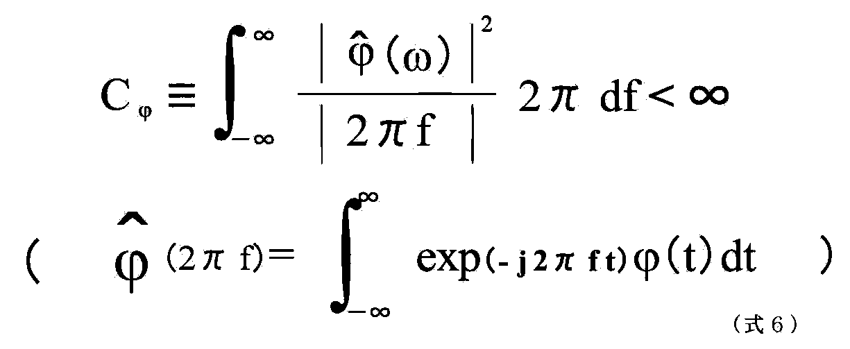
連続ウェーブレット変換では、フーリエ解析におけるParsevalの関係に似た式が成立し、次のような等長感形式、つまり「エネルギー分配則」の関係式である式7が成立する。
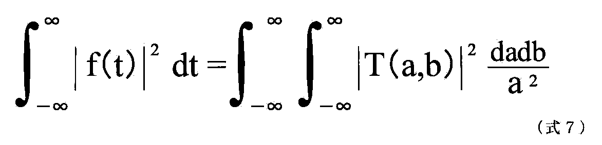
つまり、解析対象の波形に対してウェーブレット変換を行うことにより、周波数1/aと時刻bという二つの変数空間におけるそれぞれの点に対応したウェーブレット係数が算出され、このウェーブレット係数を用いて各周波数1/a、時刻bに対するエネルギーの指標としてパワーを算出することが出来る。
また下記の公知文献3には、ウェーブレット解析の応用、特に不連続信号検出機能について解説がなされている。
公知文献3:芦野隆一、山本鎮男「ウェーブレット解析~誕生・発展・応用」23~25ページ、131~133ページ(1997年6月5日発行、共立出版)
ウェーブレット解析の応用を考えたとき、その第一の機能は不連続信号の検出である。自然現象に見られる不連続信号は極めて小さく、しかも雑音に覆われている。ウェーブレット変換は、この信号の不連続を見知する能力がある。なぜならば時間軸上の不連続点でのウェーブレット係数の絶対値が、その他の点より一段と大きくなり、その不連続点を検出できるからである。
このように、種々の周波数成分が局在的傾向をもって重畳している複雑な不連続信号波形の解析には、ウェーブレット解析が有効に働くものと考えられ、本発明者はその点に着目して以下に説明する知見、及び本発明に到達したのである。
〔各症例〕
以下、2つの群の症例群、全4症例についてRSI及びウルトラディアンリズムパワー推移波形、その他の解析結果を用いた対照比較の結果を説明する。症例群は次の2つである。
症例群I (健常群)
症例数:1(第1の症例 図12~図16)
心疾患:無し
顕著なCSR:無し
睡眠の質:良好
症例群II (疾患群)
症例数:3(第2の症例 図17~図21、第3の症例 図22~26、第4の症例 図27~図31)
心疾患:慢性心不全
顕著なCSR:有り
睡眠の質:良好ではない
症例群II(疾患群)に含まれる症例の病態は次の通りである。
第2の症例:NYHA I度、BNP=47pg/ml
第3の症例:NYHA II度、BNP=115pg/ml
第4の症例:NYHA III度、BNP=1000pg/ml
ここでNYHAとは、ニューヨーク心臓協会(New York Heart Association:NYHA)が定めた心不全の症状の程度の分類であり、以下のように心不全の重症度を4種類に分類するものである。
NYHA I度:症状はなく、通常の日常生活は制限されないもの。
NYHA II度:日常生活が軽度から中等度に制限されるもの。安静時には無症状だが、普通の行動で疲労・動悸・呼吸困難・狭心痛を生じる。
NYHA III度:日常生活が高度に制限されるもの。安静時は無症状だが、平地の歩行や日常生活以下の労作によっても症状が生じる。
NYHA IV度:非常に軽度の活動でも何らかの症状を生ずる。安静時においても心不全・狭心症症状を生ずることもある。
また、BNP検査(脳性ナトリウム利尿ペプチド)とは、心臓に負担がかかると心臓(主に心室)から血液に分泌されるホルモンの量を計測する検査であって、このBNPの数値が高いほど心臓に負担がかかっているということができる。臨床的には、心筋梗塞、心不全の診断・予後判定に有用であり、血液検査で心疾患を測定できる唯一の検査である。
BNP検査値を用いた心疾患病態の把握の目安は次の通りである。
18.4 pg/ml以下:基準範囲内である。
18.5 pg/ml以上:基準範囲を超えている。病態の悪化に応じて値が上昇する。
また、各症例を説明するための図12~図31には、本発明の特徴を説明するための下記のグラフを各症例に共通して示してある。
(i)脳波SWAトレンド:5分間の脳波から前述のSWAを算出し、これを50秒ずつずらして8時間まで繰り返し施行したデータのトレンドグラフである。従って、このグラフのサンプリング周波数は50秒ごと(0.02Hz)となる。
(ii)呼吸周期RSIトレンド:5分間の呼吸曲線から、前述したRSIを算出し、これを50秒ずつずらして8時間まで繰り返し施行したデータのトレンドグラフである。従って、このグラフのサンプリング周波数は50秒ごと(0.02Hz)となる。
(i)、(ii)とも波形をフィルタリングして得られた包絡線を付記し、波形トレンドのリズムを見やすくしてある。
(iii)脳波SWAおよび呼吸周期RSIの周波数分布
上記約8時間のSWAとRSI(0.02Hz)のデータに対し、最大エントロピー法(Maximum Entropy Method:MEM)による周波数分析を行い、これらの時系列信号に含まれる主要な振動成分を抽出したものである。周波数領域の把握を重視し、それぞれの最大パワーで規格化して表示してある。
(iv)脳波SWA自己相関関数
上記のSWA波形の自己相関関数、すなわちSWA波形どうしのずらし比較による相関係数の推移を示したものである。波形に潜む重要なリズムの存在が統計学的に証明するためのものである。
なお、重複する図示を省略して説明を明瞭とするため、第1の症例では(xi)、(xii)を省略し、第2~第4の症例では、(ix)、(x)を省略している。
(v)呼吸周期RS自己相関関数
同じく、上記のRSI波形の自己相関関数、すなわちRSI波形どうしのずらし比較による相関係数の推移を示したものである。
(vi)脳波SWAおよび呼吸周期RSIの相互相関関数
上記のSWA波形およびRSI波形相互のずらし比較による相関係数の推移を示したものである。両者の相関が高いのか否かを統計学的に証明するためのグラフである。
(vii)脳波SWAトレンド
(i)の波形を、連続波形としたものである。
(viii)脳波SWAトレンドに含まれるウルトラディアンパワーの推移
(vii)の波形に含まれる脳波SWAウルトラディアンリズムパワーの推移を、上記のウェーブレット解析手法を用いてグラフ化したもの、すなわち0.0001~0.0003Hz(90分周期)のパワーの平均値を追跡したものであり、眠りの深さの推移を示している。
(ix)呼吸周期RSIトレンド
(ii)の波形を、連続波形としたものである。
(x)呼吸周期RSIトレンドに含まれるウルトラディアンパワーの推移
(ix)の波形に含まれるウルトラディアンリズムパワーの推移を、上記のウェーブレット解析手法を用いてグラフ化したもの、すなわち0.0001~0.0003Hz(90分周期)のパワーの平均値を追跡したものであり、眠りの深さの推移を示している。
(xi)脳波SWAトレンドに含まれるウルトラディアンパワーの推移
(viii)と同一である。
(xii)呼吸周期RSIトレンドに含まれるウルトラディアンパワーの推移
(x)と同一である。
上記の第1~第4の症例に関する、(i)~(xii)の各グラフから、次の点が認められる。
まず、(i)、(ii)から、脳波SWAトレンドと呼吸周期RSIトレンドの時相が一致しているのがよく分かる。同じくこのデータから、ある程度の睡眠の深さになると呼吸が規則正しく安定化し、それ以上眠りが深くなっても、呼吸の規則性は一定である(規則性が上限に達している)ことが理解できる。RSIが睡眠中規則正しくなるためにはSWAの閾値があることが予想される。第1の症例の一番右のSWAピークの出現時にRSIは反応していないためである。
次に、(iii)から、0.0001~0.0003Hz(約90~100分周期)のウルトラディアンリズムが、脳波SWAトレンド、呼吸周期RSIトレンドの両者に明瞭に認められる。
また、(iv)、(v)、(vi)から、自己相関関数では、脳波SWAトレンド、呼吸周期RSIトレンドの両者に周期性があり、自己相関関数波形のピーク間隔からその周期が約90~100分であり、ウルトラディアンリズムに一致することが分かる。相互相関関数で両者の最大相関は0.9前後の高い値を示しており、両者が密接に関連していること意味する。
特に留意すべき点は、脳波SWAトレンド、呼吸周期RSIトレンドに含まれるウルトラディアンリズムの周期性が、健常者がより大きく、NYHA段階が進んで心疾患が重篤になっていくほど周期性の発現が小さくなっている点である。これはそれぞれのトレンド波形の自己相関関数に見られるピークの大きさの相違から知ることが出来る。
また、よく眠っている健常者のデータ(第1の症例)と、心不全患者のデータ(第2~第4の症例)を対比させると脳波SWAと呼吸周期RSIそれぞれの特徴がわかり、次のような興味深い性質が理解できる。
脳波SWAは眠りの深さに応じてパワーが大きくなっているが、呼吸周期RSIでは、ある一定以上の深い眠りにおいて規則性が明瞭となる閾値のようなものがあると予想される。ある程度の眠りになると急激に規則正しくなりそれ以上は規則正しくなり得ない(規則性は上限値がある)ためである。
従って、呼吸周期RSIの山の大きさはある程度以上で一定となってしまうため、脳波SWAのようなウェーブレット解析では最大値を見つけ難くなる可能性がある。
とりわけ健常者のように一晩中眠りの深い症例では呼吸周期RSIのwaveletは、幅の広い台形のようなウルトラディアンパワーを示しやすいのではないかと思われる(第1の症例)。
むしろ眠りの障害されている重症な患者で時々出る深い眠りに一致して、呼吸周期RSIがピークを示しやすいと考えられる(第2、第3の症例)。
以上のことから、呼吸周期RSIはある一定以上の深い眠り(ノンREM睡眠、深さとの対比が必要)を鋭敏に反映すると思われる。
以上の考察は、各症例の脳波SWAトレンド、呼吸周期RSIトレンドの対比を主な視点として行なったものである。
次に、各症例の呼吸周期RSIトレンド、およびそこに含まれるウルトラディアンリズムパワーの推移に着目し、症例群I(健常群)、症例群II(疾患群)の群間の差異について考察する。
これら2つの群を、各図示されたRSI、ウルトラディアンリズムパワーの推移から比較対照すると、群間で次の相違点が顕著である。従って、RSI、そのウルトラディアンリズム波形推移あるいはその双方を用いて、「慢性心不全及び顕著なCSRが無く、睡眠の質が良好である群」と「慢性心不全及び顕著なCSRがあり、睡眠の質が良好ではない群」とを診断で識別することが可能である。
特に明瞭な相違点は、次の通りである。

症例を用いた説明の最後として、第5の症例を、図32、図33を用いて説明する。
この第5の症例は慢性心不全に罹患し、顕著なチェーンストークス呼吸が認められ、睡眠の質は不良である。
図32はこの第5の症例患者の、酸素療法投与前の、RSIおよびウルトラディアンリズムの睡眠中の推移を示したものである。
図33は同じく90%酸素を継続的に投与する、酸素療法開始後の第5の症例患者のRSIおよびウルトラディアンリズムの睡眠中の推移を示したものである。
図32および図33を対比することによって、酸素投与開始後は、RSIの値が増大するとともに、RSIの値が顕著に大きな時間領域すなわち患者の呼吸周期が安定しており睡眠の深さが深い時間領域が、投与前と比較して拡大していることが明瞭に理解できる。
更に、同じく双方の図を対比することによって、ウルトラディアンパワーの大きさが投与前よりも増大しており、このことからも酸素投与によって患者の睡眠の質が改善されていることが理解できる。
〔変形例その1 ~ テレメディスンへの応用〕
本発明の実施に際しては上記実施形態以外にも種々の変形が考えられる。
例えば呼吸波形を可搬型呼吸波形計測装置で計測記録し、その後で医療機関へ搬送するのではなく、通信路を介して直接解析装置へ送信するテレメディスンシステムでの実施や、呼吸波形中の各周波数成分の推移を単に表示するのみならず、ピークの数や大きさや明瞭さや位置に応じてスクリーニング的な自動評価を行う(但し確定診断は医療者が行う)構成なども可能である。
〔変形例その2 ~ 呼吸周波数安定度の推移を表示する〕
次に、本発明におけるシステムの変形例として特に重要度を有する構成を説明する。
本発明者は、上記のような被験者の呼吸波形計測情報を用いた睡眠評価診断を多数の症例で行う中で、次のような知見を得た。
上述したように、睡眠は6種類の睡眠ステージが典型的には90分周期で一晩に3回繰り返され、この各周期における生理データの変化は下記のように脳波の徐波成分(SWA:Slow Wave Activity)で明瞭に観察することが出来る。そして、睡眠時無呼吸など何らかの原因によって睡眠の質を含めた快適度が低下した被験者ではこのSWAにおける睡眠段階の周期がくずれて明瞭に観察できないことがわかっている。
そこで、睡眠中の被験者の呼吸動作に注目し、計測して得られる呼吸周期の変動、特に呼吸周期の安定性に着目すればこの睡眠周期の観察、ひいては睡眠の質を含めた快適度の評価を行える可能性がある。
呼吸周期の安定性とは、計測で得られた呼吸波形から呼吸周期の帯域を抽出し、まず呼吸周波数の平均値(X bar)を算出し、更に既知の統計的手法を用いて、呼吸周波数の標準偏差(Sd)を算出し、この標準偏差(Sd)の逆数を取ることで示すことが出来る。
先に説明した実施態様と同様に、計測された呼吸波形の標準偏差の逆数を、ここではRSI(Respiration Stability Index)と呼ぶこととする。このRSIを一晩の睡眠において時間推移がわかるようにグラフ化すれば、睡眠周期が明瞭に現れており睡眠の質を含めた快適度が良いのかあるいは、明瞭に観察できず睡眠の質を含めた快適度が悪いのか、を医療者が観察して容易に判断できるはずである。
そこで本発明における変形例のシステムでは、入力された呼吸波形から、5分間というフーリエ窓期間について5秒間ずつ時間をずらして高速フーリエ変換(FFT)を実行して得られた、各フーリエ窓期間の起点となる時刻における複数のフーリエスペクトルから、典型的な人体の呼吸周期である0.4Hzが含まれる0.1~0.5Hzの周波数領域を抽出する点は先に説明した構成と同様である。
更に本発明における変形例のシステムでは、解析部3−3が、上記の50秒間のずらし間隔で得られるフーリエ窓ごとの呼吸周波数帯域に含まれる周波数の平均値(X bar)および標準偏差(Sd)を算出し、このSdの逆数である上記のRSIを、この50秒間のずらし間隔を有する個々のフーリエ窓期間ごとに算出し時間軸に対して直行する軸上にプロットした、RSIの時間推移を示すグラフを作成し、これを演算結果の情報として、表示、印刷あるいは外部への出力をする。
このRSIのグラフを観察すれば、睡眠周期の明瞭さ、ひいては睡眠の質を含めた快適度を容易に観察、診断することが可能である。
〔変形例その3 ~ 睡眠の質を含めた快適度を自動的に評価する装置〕
上記説明した変形例では、呼吸周波数の標準偏差の逆数などから、呼吸周期の規則性を示す指標RSIを算出し、このRSIの時間的推移を表示などして医療者などが観察、診断する方法であった。
しかし、睡眠の質を含めた快適度がよく睡眠周期が明瞭に現れる場合のRSIの推移グラフはわかっているので、得られたSRI推移グラフから睡眠の質を含めた快適度を自動で判定することが可能である。
具体的には、RSIグラフのピークの大きさ、グラフが時間軸との間に挟む面積すなわちRSIグラフの時間積分値、予想されるRSI推移グラフ立ち上がり時刻すなわち呼吸安定期始まり時刻からのずれ、その被験者のあるいは一般的な被験者の理想的な睡眠の質を含めた快適度が良い場合のRSIグラフからの幾何学的な数値からされた図形的変位量などである。また他にも可能である。
これらのアプローチから上記の本発明における睡眠評価システム1の構成を利用して、睡眠の質を含めた快適度を自動評価する構成は容易に到達できるので、詳細具体的な構成の説明は省略する。
次に、本発明の他の変形例として、上記に説明を行った呼吸波形解析に基づく睡眠評価技術を、患者の治療に用いる治療機器などに具体的に応用した実施例などを説明する。
〔変形例その4 ~ 気道陽圧式呼吸補助装置に関する発明の実施形態〕
まず、気道閉塞に起因する睡眠時無呼吸症候群(以下、SAS:Sleep Apnea Syndromeともいう)の治療装置である、気道陽圧式呼吸補助装置(以下、「CPAP装置」あるいは「呼吸補助装置」ともいう)に本発明を適用した実施態様について説明を行う。
なお、以下に説明を行うCPAP装置に関する実施例では、患者へ送出する気体の送出圧制御を、装置内部に設けられた制御部が行うものである。
ところで、患者への気体送出を行う装置と、その送出圧の制御を行う装置とを一体とはせずに別体の装置とした構成も、既に市場に導入されてきている。そこで、以下の説明のようなCPAP装置内部に気体送出を行う機能部と、送出圧制御を行う機能部とを一体に設ける構成の他に、送出制御を別体の装置としてもよく、以下の説明ではこのような変形例をも範囲に含めて構成の説明を行うこととする。
CPAP装置は、大気を30cmH2O程度まで昇圧して呼吸の補助手段として鼻マスクを用いて鼻孔部へ供給する気道陽圧式呼吸補助装置である。
詳細には、睡眠時無呼吸症候群の治療手段の一方法として、睡眠時に昇圧空気を鼻孔部を通して呼吸気道内に送気し、気道内を持続的に陽圧に維持せしめて呼吸気流を気道内に導通させ、気道部の閉塞に起因する呼吸停止がもたらす血液中の酸素濃度低下を防止するために提供される医療用具である。CPAP装置の具体的な構成は、例えば特開平7−275362号公報に開示がなされている。
睡眠時無呼吸症候群(SAS)とは、睡眠中に断続的に無呼吸を繰返し、その結果、日中傾眠などの種々の症状を呈する疾患の総称である。
無呼吸(apnea)とは、10秒以上の気流の停止と定義され、SASは、一晩7時間の睡眠中に30回以上の無呼吸がある場合、無呼吸指数 AI(apnea index:睡眠1時間あたりの無呼吸の回数)が、AI≧5(回/時間)の場合、あるいは実際の臨床では、無呼吸に低呼吸を加味した無呼吸低呼吸指数(AHI)が用いられる。
無呼吸低呼吸指数(Apnea hypopnea Index):睡眠1時間あたりの無呼吸と低呼吸を合わせた回数。
低呼吸(hypopnea):気道が完全に閉じるのではなく、狭小化のために換気量が少なくなった状態。換気の50%以上の低下に、酸素飽和度(SpO2)の3%以上の低下を伴うもの。
SASは、その原因から、閉塞型(閉塞性ともいう)(Obstructive Sleep apnea=OSA、睡眠中に上気道が閉塞して気流が停止するもので、無呼吸の間でも胸壁と腹壁の呼吸運動が認められるが、動きは互いに逆になるという奇異運動を示す)、中枢型(中枢性ともいう)(Central Sleep apnea=CSA、呼吸中枢の機能異常によりREM期を中心とした睡眠中に呼吸筋への刺激が消失して無呼吸となる)、及びOSAとCSAとの混合型(中枢型無呼吸で始まり、後半になって閉塞型無呼吸に移行する場合が多い。閉塞型無呼吸の一つとして分類することが多い)に分類される。
これらの中でCPAP装置による治療の対象となる患者は、OSAの患者である。
OSAは、上気道の閉塞によって無呼吸、低呼吸が起きるために発症する。
閉塞の原因は、(A)形態的異常(肥満によって気道に脂肪沈着する、扁桃肥大、巨舌症、鼻中隔彎曲症、アデノイド、小顎症(あごが小さい)など)、と、(B)機能的異常(気道を構成している筋肉の保持する力が低下する)である。
健常人の睡眠パターンは眠り始めに深い睡眠(ノンレム睡眠)が見られるのに対し、OSA患者は無呼吸のため血中酸素が低下し、胸腔内圧力が陰圧となって睡眠中に何度も覚醒反応が発生し、深い眠りが得られないことから、日中傾眠などの症状を呈する。
このようなOSA患者に対してCPAP装置は、鼻マスクを介して一定陽圧の空気を送り込み、上気道を広げ、この結果、気道閉塞を解消して無呼吸を防止するよう動作を行う。気道を広げるための圧力(以下「陽圧」ともいう)は患者個々に異なる。
また、心不全などの特定の疾患に特徴的に見られるCSA等の呼吸減衰に対しては、患者気道に印加される圧縮空気の圧力レベル(陽圧)を一定の圧力を保つCPAP以外にも、患者の呼気期間と吸気期間とで2つの異なる圧力としたもの(Bilevel−PAPと呼ぶ)、患者の呼吸の状態(有無、気流レベル、間隔など)を常時モニターしてその瞬間ごとに最適な圧を変化させながら印加するもの(サーボ型自動制御補助換気と呼ぶ)などの補助人工呼吸装置を用いる場合があり、その至適圧力は患者個々に、また症状によって異なる。
いずれの方法にせよ、陽圧レベルの決定は医師の所見に基づいて処方として決定がなされる。従来は治療対象患者の睡眠の質を含めた快適度を直接評価して、睡眠の質を含めた快適度を良好に保つために最適な陽圧レベルを決定する構成は知られていなかった。
これら従来の課題を解決するために、本実施形態におけるCPAP装置21aは、図34に示すとおり、次の構成を有している。
まずCPAP装置本体21bは、上記した陽圧レベルを可変制御可能に構成した装置であって、圧縮空気を生成して装置外へ送出するブロア21b−1、そのブロア21b−1の送出する圧縮空気の圧力(陽圧レベル)の変更制御を含めてCPAP装置本体21bの運転制御を行うCPAP制御部21b−2を有している。
CPAP装置本体21bから送出される圧縮空気(陽圧空気)は導管21eを経由してマスク21fから患者の気道へ供給がなされる。
なおCPAP装置本体21bの構成は、以下に述べる特徴的構成を除いて、既に開示されている従来技術構成を用いることが可能である。
呼吸センサー21dは、上記の睡眠評価システム1における呼吸センサーと同様の構成を有している。
睡眠状態解析部21cは、CPAP装置本体21bと別体または一体に設けられ、呼吸センサー21d出力を受けて増幅する呼吸波形検出増幅部21c−1、そのアナログ出力をデジタル化するAD変換部21c−2、デジタル化した波形の情報を蓄積し、アクセス可能とするメモリー部21c−3、及び以下に述べる睡眠状態解析部21c−4を有している。
睡眠状態解析部21c−4は、上記のように呼吸センサー21dから入力する検出波形のデジタル化信号を得て、フーリエ窓期間中のフーリエ変換を順次実行し、呼吸周波数帯域の抽出信号、およびこれから得られるRSIの時間推移をリアルタイムに生成することが可能である。
本実施例CPAP装置21aの動作原理は次の通りである。
睡眠は6種類の睡眠ステージが典型的には90分周期で一晩に3回繰り返され、この各周期における生理データの変化は下記のように脳波の徐波成分(SWA:Slow Wave Activity)で明瞭に観察することが出来る。そして、睡眠時無呼吸など何らかの原因によって睡眠の質を含めた快適度が低下した被験者ではこのSWAにおける睡眠段階の周期がくずれて明瞭に観察できないことがわかっている。
そこで、睡眠中の被験者の呼吸動作に注目し、計測して得られる呼吸周期の変動、特に呼吸周期の安定性に着目すればこの睡眠周期の観察、ひいては睡眠の質を含めた快適度の評価を行える可能性がある。
呼吸周期の安定性とは、計測で得られた呼吸波形から呼吸周期の帯域を抽出し、まず呼吸周波数の平均値(X bar)を算出し、更に既知の統計的手法を用いて、呼吸周波数の標準偏差(Sd)を算出し、この標準偏差(Sd)の逆数を取ることで示すことが出来る。
先に説明した実施態様と同様に、計測された呼吸波形の標準偏差の逆数を、ここではRSI(Respiration Stability Index)と呼ぶこととする。このRSIを一晩の睡眠において時間推移がわかるようにグラフ化すれば、睡眠周期が明瞭に現れており睡眠の質を含めた快適度が良いのかあるいは、明瞭に観察できず睡眠の質を含めた快適度が悪いのか、を医療者が観察して容易に判断できるはずであるとともに、得られた被験者のRSIの時間推移が、良質な睡眠における推移に近づくよう、先に説明した睡眠の質を含めた快適度自動評価装置の構成を利用して、陽圧空気の圧力を制御すれば、個々の患者に合わせて、あるいはまた患者のその日の状態に合わせて、最適なCPAP治療条件で陽圧空気が患者へ供給され、最適な睡眠状態が得られる。
この陽圧レベル制御はフィードバック制御を行うことが有効である。睡眠状態解析部21c−4とCPAP制御部21b−2とは、睡眠中の単数あるいは複数の時間ポイントで解析と陽圧レベルの変更を行ってもよいし、常時、RSIの時間推移波形をモニターして、リアルタイムに最適な陽圧レベルとなるよう制御を継続してもよい。
また、この陽圧レベル制御は、この患者の陽圧レベルを決定するための検査としてその場合にだけ実行する方法、あるいはこのCPAP装置21aを用いてOSA患者の治療を行う際には常に制御を行う方法のいずれでもよい。
ところで、上記の説明ではCPAP装置21aを用いて治療を行う対象の患者像として、従来構成のCPAP装置と同様に睡眠時無呼吸症候群の患者として説明した。
一方、本発明実施形態にかかるCPAP装置21aでは、その構成上の特徴から、上記の睡眠時無呼吸症候群患者に加えて、対象を慢性心疾患患者、特に心不全患者に広げることが可能となる。
すなわち、慢性心疾患患者、特に心不全患者に対して、呼吸ポンプ機能を補助するBilevel−PAPによる治療が血行動態を改善させることは知られている。
しかし、慢性心疾患患者は、心不全などによって交感神経活性が過度に上昇しており、すなわち興奮状態にあるため、入眠障害があることが多く、その中でマスク装着が必要なBi−PAP治療はさらに入眠・睡眠の質を含めた快適度を悪化させる可能性もあり、長期に使用することは避ける場合があった。
それを解消するために、本実施形態のCPAP装置21aを用いれば、呼吸波形解析の結果をフィードバックし、圧力レベル、圧力波形の調整を調整して、夜間の使用を可能とし、長期治療が可能となる。
次に、本実施形態の気道陽圧式呼吸補助装置において、患者への印加圧力が一定であるCPAP装置や、圧力変化が二相しかないBilevel−PAPとは異なり、患者の呼吸の状態(有無、気流レベル、間隔など)を常時モニターしてその瞬間ごとに最適な圧を変化させながら印加して、患者の肺換気量、呼吸数の両方かあるいはいずれか一方が予め定めた一定量に近づくように自動制御を行うサーボ型自動制御補助換気装置(Adaptive Servo Ventilator:ASV)を前提として構成した場合には、本発明の効果がより増進される点を説明する。
正常呼吸(毎分8~15回)において、心拍数は吸気時に増大し呼気時に減少する。この呼吸性洞不整脈(呼吸によって起こる心拍数の変化)はアトロピンにより心臓迷走神経を遮断するとほぼ完全に消失することから、主に心臓迷走神経活動が関与していることがわかる。
吸気時相に同期して迷走神経活動が減弱する原因の一つに、呼吸中枢からの干渉により心臓迷走神経活動が抑制される中枢性機序がある(Hamlin RL.Smith CR,Smetzer DL.Sinus arrhythmia in the dogs.Am J Physiol 1966;210:321−328.Shykoff BE,Naqvi SJ,Menon AS,Slutsky AS.Respiratory sinus arrhythmia in dogs.J Clin Invest 1991;87:1612−1627.)。
これは吸気時の横隔膜神経の活動に同期した心拍増加が、たとえ肺や胸郭の動きがなくとも認められるという事実に基づく。
一方、呼吸性心拍変動を惹起する末梢性機序として、肺の伸展受容器からの求心性入力により迷走神経活動が吸気時に同期して遮断されるgating effectsがある。事実、心臓への迷走神経遠心路が保たれているが、肺からの迷走神経求心路が遮断されている肺移植患者において、呼吸性心拍変動が明らかに減弱することが知られている(Tara BH.Simon PM,Dempsey JA,Skatrud JB,Iber C.Respiratory sinus arrhythmia in humans:an obligatory role for vagal feedback from the lungs.J Appl Physiol 1995;78:638−645.)。
従って、上記に説明したように、呼吸気の圧力を指標として制御を行うCPAP装置において、治療患者の呼吸動作の周期や換気鼠が睡眠の過程において一定ではなく変動をした場合に呼吸周波数の推移に影響を与える可能性がある。
ところが、サーボ型自動制御補助換気装置は、先に説明したとおり、治療患者の呼吸の状態(有無、気流レベル、間隔など)を常時モニターしてその瞬間ごとに最適な圧を変化させながら患者の肺換気量と、患者の呼吸数の両方あるいはいずれか一方を予め決められた一定値に近づくように制御を行うものであるから、このサーボ型自動制御補助換気装置を用いた場合には睡眠中の患者の呼吸動作における動作周期や肺換気量の変動が相対的に少なくなるよう、換気装置によるコントロールが可能となる。
従って、サーボ型自動制御補助換気装置を前提として、上記に説明したごとくの特徴を有する本実施例の気道陽圧式呼吸補助装置を構成した場合には、患者の呼吸周期の規則性を示す指標、例えばRSIの時間推移を用いて、睡眠の質を含めた快適度が高まるようにコントロールを行うことが出来るので、コントロールのループが患者の呼吸周波数のみを介することからダイレクトであり制御の応答性がより良くなり、この結果、より精度の高い睡眠評価結果とこれを用いたコントロールが実行できることから、本実施形態の特有の効果である、より良質な睡眠を治療患者に提供するという点を他のタイプのCPAP装置(サーボ型自動制御補助換気装置ではないタイプ)よりも更に増進させることができる。
なお、上記のサーボ型自動制御補助換気装置は、「オートセットCS」の製品名で2007年に帝人ファーマ株式会社が市場導入を行っている。
上記した「オートセットCS」は、下記に略号を用いて列挙する各国の特許または特許出願等によって、その構成の技術的特徴部分がカバーされている。
AU 691200,AU 697652,AU 702820,AU 709279,AU 724589,AU 730844,AU 731800,AU 736723,AU 734771,AU 750095,AU 750761,AU 756622,AU 761189,AU 2002306200,CA 2263126,EP 0661071,EP 1318307,JP 3635097,JP 3737698,NZ 527088,US 4944310,US 5199424,US 5245995,US 5522382,US 5704345,US 6029665,US 6138675,US 6152129,US 6240921,US 6279569,US 6363933,US 6367474,US 6398739,US 6425395,US 6502572,US 6532959,US 6591834,US 6659101,US 6945248,US 6951217,US 7004908,US 7040317,US 7077132。
〔呼吸補助装置のタイトレーションに用いる検査装置に関する発明の実施形態〕
次に、上記説明を行った本発明の実施形態である、CPAPを含めた呼吸補助装置のタイトレーションに用いることが有効である、検査装置に関する発明の実施形態を説明する。
これら呼吸補助装置のタイトレーションとは、CPAPなど呼吸補助装置の適正圧(治療圧)の決定を医療者などが行う作業であって、例えば、ワールドワイドウェブ上に閲覧可能に配置された情報「神戸共同病院 睡眠時む呼吸症行群」<http://homepage3.nifty.com/SAS−kyo/titration.pdf#search=’タイトレーション’>に詳細な説明がなされている。
従来は、終夜睡眠ポリグラフィ(PSG)検査を行いながら、呼吸補助装置の作動圧力を最小圧から開始して、呼吸状態を観察しながら作動圧力を調整し、無呼吸や、低呼吸状態が観察されるごとに無呼吸や低呼吸、イビキが解消されるように手動で圧力を上昇・下降など可変させていく(マニュアル・タイトレーション:手動圧調整)方法があり、最終的に患者の睡眠状態が良好で、呼吸障害が解消される最小の圧が指摘圧(治療圧)となる。この方法は終夜観察という多大な労力を要する作業であり、自動的に器械が圧力を可変し記録してくれる、Auto−CPAP装置を用いて人的な労力を省力化する、オート・タイトレーションという方法もある。
また、上記のように睡眠中の被験者を対象としてタイトレーション作業を行う方法の他に、覚醒中の被験者に対して、使用を想定している呼吸補助装置などの医療機器を装着し、短期間の使用試行を行って、被験者へのこの医療機器の適合性、あるいは設定条件の決定などを行う方法もある。
以後の説明では、睡眠中の被験者に対するタイトレーション作業に限らず、上記のような覚醒中の被験者へのタイトレーション作業を含めて、「タイトレーション」という文言を用いて説明を行うこととする。
本発明はこのタイトレーション作業を、より人体の生理に即した、精度が高く且つ作業効率のよい改良を実現するものであって、具体的には、睡眠中または覚醒中の被験者に送出される呼吸補助装置の作動圧を、手動または自動にて変化させるとともに作動圧の時間変化を記録し、且つ、被験者の呼吸波形を継続的に記録してき、上記したRSIの時間変化波形を生成記録するものである。
作動圧およびRSIの時間変化は、タイトレーションを行う医療者がリアルタイムに観察して診断に用いても良いし、これらの波形を記録しておいたり、記録したデータに基づき後刻波形を生成して、これらの波形をモニター装置で表示したり、プリンター装置で印刷したり、あるいは外部へ送信を行う。
医療者は同時に観察可能な、作動圧変化波形とRSI波形とを比較して、例えば5分ごとに作動圧を変化させた場合に、それに伴って変化をするRSI波形が極大値を有する場合に、そのときの作動圧を適切な治療圧力として決定することが可能となる。これは人体の呼吸動作周期の挙動が脳中枢からの直接的な支配を受けており、外乱要素が少ないので、他の生理情報例えば心拍数などを観察することと比較して、呼吸補助装置による圧力印加の効果を直接観察することができ、タイトレーションの精度をより高めることが出来るからである。
他にも、(1)圧縮空気の圧力値、(2)圧縮空気の圧力値の変化パターン、及び(3)上記に説明した、CPAP装置、バイレベルPAP装置、ASV(サーボ型自動制御補助換気装置)など複数ある呼吸補助装置の中での装置の選択、の内の少なくともいずれかを治療に適するように医療者が決定するようにしてもよい。
また、呼吸周期の挙動を観察することから、睡眠中に限られること無く覚醒中の観察によっても適切なタイトレーションを行うことが出来、入院を要せず外来診療の場、あるいは患者宅での往診診療の場でも短時間の内にタイトレーションを完了することが出来るので、患者の負担が軽減されるとともに医療経済効果を向上させることが出来る。
なお、本発明によるタイトレーションは、CPAPに限らず、患者の自発呼吸の下で加圧空気やその他の呼吸気体を送出する、様々な呼吸補助装置において有効であるが、上記したような従来技術を用いたタイトレーションは、タイトレーションのための測定時にのみ有効で、症状の変化が生じた場合には再入院してタイトレーションを再実施する以外に方法がなかった。
それに対して上記したとおりの本発明実施形態によるタイトレーションを行うことで、睡眠の質や快適度を直接評価できることから、入院時に限らず例えば在宅においても、症状変化など所望のタイミングで患者自身がスイッチ操作を行ってタイトレーションを任意に実施し、症状に応じた最適条件を発見し、自動で設定することが可能となる。
〔睡眠導入装置に関する発明の実施形態〕
次に、本発明の他の実施形態として、不眠症患者あるいは健常者を睡眠状態に導いて良好な睡眠を実現することを目的とした、睡眠導入装置に本発明を適応した例を説明する。
この種の睡眠導入装置は、例えば、特許第3868326号公報には、これから入眠しようとする患者に対してスピーカーから音を発声して聴音せしめ、この音に対して患者がジョイスティックを操作した動作の内容を分析することで、より早く患者が入眠にいたるように発声音を選択制御しようとするものである。
また、特開2003−199831号公報には、枕に仕込んだスピーカーから超音波を発声させ、この超音波の態様を時間順次に変えることによって対象者をまずリラックスさせ、その後次第に入眠へ導こうとするものである。
しかしながらこれら従来技術構成によれば、音や超音波など何らかの物理刺激を対象者に加えるものの、それら物理刺激はあらかじめプログラムとして決定されていたり、あるいはまだ入眠に至らない対象者の動作から睡眠の進行を推定することによって選択しようとするばかりであって、対象者の睡眠の状態や睡眠の質を含めた快適度を直接評価しつつ、フィードバック制御を用いて最適な物理刺激の態様を選択しようとするものではなかった。
それに対して本実施形態の睡眠導入装置22aは、図35に例示した下記の構成を有している。
まず物理刺激装置22bは、これから入眠をしようとする対象者に対して、出力部22b−1から光、音、超音波、熱、風、画像、匂い、接触刺激、電気刺激、磁気刺激など何らかの物理刺激を与えるよう構成され、且つその物理刺激の態様を、物理刺激制御部22b−2の機能により変化させることができる。例えば物理刺激が光であれば、その強度、波長(色)、点滅の有無や間隔、発光体の面積や形や位置、さらには光の発光の有無までをも変化させることができる。
あるいは物理刺激が音であれば、その強度、波長(音程)、発声パターンや間隔、発声の方向や位置、さらには発声の有無までをも変化させることができる。
呼吸センサー22dは、上記の睡眠評価システム1における呼吸センサーと同様の構成を有している。
睡眠状態解析部22cは、物理刺激装置22bと別体または一体に設けられ、呼吸センサー22d出力を受けて増幅する呼吸波形検出増幅部22c−1、そのアナログ出力をデジタル化するAD変換部22c−2、デジタル化した波形の情報を蓄積し、アクセス可能とするメモリー部22c−3、及び以下に述べる睡眠状態解析部22c−4を有している。
睡眠状態解析部22c−4は、上記のように呼吸センサー22dから入力する検出波形のデジタル化信号を得て、フーリエ窓期間中のフーリエ変換を順次実行し、呼吸周波数帯域の抽出信号、およびこれから得られる例えば上記のRSIの時間推移をリアルタイムに生成することが可能である。
従ってこのRSIなどの推移を見て、睡眠の質を含めた快適度がより良くなるように、睡眠導入装置22aの運転条件を制御するよう構成されている。
〔マッサージ装置に関する発明の実施形態〕
次に、本発明の他の実施形態として、対象者に対して機構的なアタッチメント部が揉み解し動作などを自動的に行う、マッサージ装置に本発明を適応した例を説明する。
この種のマッサージ装置は、例えば、特開2007−89716号公報には、パラレルリンク機構式のマッサージ装置において、施療子を人体に対して独立に上下方向、左右幅方向、及び出退方向に安定かつ再現性良く移動制御して施療子に所望のマッサージ動作を行わせることを可能とするマッサージ装置が開示されている。
また、特開2003−310679号公報には、ふくらはぎ、かかと、つま先までを同時に密着し得るように略ブーツ形状に形成すると共に、つま先から脚を入れる際に開くように接合部を開閉自在に設けたふくらはぎ用袷部を有する脚用押圧袋と、脚用押圧袋2の表皮材の略全面に張り付けた空気充填用袋体と、空気充填用袋体に空気の供給と排気をするエアポンプと、空気充填用袋体に設けた給排気孔とエアポンプとを連結する連結管と、を備えた脚用マッサージ装置が開示されている。
しかしながらこれら従来技術構成によれば、マッサージの動作パターンはあらかじめプログラムとして決定されていたり、あるいはマッサージの対象者が抱く主観的な快感や不快感に基づいて選択しようとするばかりであって、対象者の生理状態を直接評価しつつ、フィードバック制御を用いて最適なマッサージパターンを選択しようとするものではなかった。
それに対して本実施形態であるマッサージ装置23aは、図36に例示するように下記の構成を有している。
まず、マッサージ本体23bは次のマッサージ刺激部23b−1、マッサージパターン制御部23b−2を有する。
マッサージ刺激部23b−1は、マッサージの対象者に対して、ローラ、ハンド、エアカフなどアタッチメントを用いてマッサージ動作を行うための構成であって、具体的には公知のマッサージ装置と同様のアタッチメントを用いることができる。
マッサージパターン制御部23b−2は上記のマッサージ刺激部23b−1が実行するマッサージの態様を変更制御するもので、マッサージの動作有無や、マッサージの強さやパターンなど動作の全てが制御対象である。
呼吸センサー23bは、既に説明したとおりの構成を有している。
睡眠状態解析部23cは、物理刺激装置23bと別体または一体に設けられ、パルスオキシメータ23d出力を受けて増幅する呼吸波形検出増幅部23c−1、そのアナログ出力をデジタル化するAD変換部23c−2、デジタル化した波形の情報を蓄積し、アクセス可能とするメモリー部23c−3、及び以下に述べる睡眠状態解析部23c−4を有している。
睡眠状態解析部23c−4は、上記のように呼吸センサー23dから入力する検出波形のデジタル化信号を得て、フーリエ窓期間中のフーリエ変換を順次実行し、呼吸周波数帯域の抽出信号、およびこれから得られる、例えば上記のRSIの時間推移をリアルタイムに生成することが可能である。
従ってこのRSIなどの推移を見て、睡眠の質を含めた快適度がより良くなるように、マッサージ装置23aの運転条件を制御するよう構成されている。
〔血圧測定システムに関する発明の実施形態〕
次に、本発明の他の実施形態として、信頼性、再現性が良好、かつ簡潔な態様で被験者の血圧を測定するための、血圧測定システムに本発明を適応した例を説明する。
島田和幸ほか、循環器病の診断と治療に関するガイドライン1998−1999年度合同研究班報告「24時間血圧計の使用(ABPM)基準に関するガイドライン」(Japanese Circulation Journal Vol.64,Suppl.V,2000。以下「ガイドライン」という。)によれば、人体の血圧値は、活動時、安静時、睡眠時など多くの条件下の血圧値が変動し、必ずしもこれらの血圧と診察室での随時血圧とは相関しないことが知られている。
上記のガイドラインにも示されているように、高血圧患者の血圧値を測定するためには、24時間血圧測定法(ambulatory blood pressure monitoring:ABPM法)が用いられる。
1)診察室あるいは家庭での血圧が大きく変動する場合
2)白衣高血圧(white coat hypertension:通常の日常生活においては、正常血圧であるが、医療環境においては再現性よく、繰り返し高血圧を呈するもの)が疑われる場合
3)薬物治療抵抗性の高血圧の場合
4)降圧薬投与中に低血圧を示唆する徴候がみられる場合
5)早朝に高血圧を示す場合
ABPM法の概要は、被験者に血圧計を装着し、典型的には15分~30分間隔で、睡眠中を含めた期間中に血圧測定を行う方法である。
また夜間血圧の評価はこのABPM法によってのみ可能である。
ところで、この夜間に測定される血圧値の信頼性、精度について、上記のガイドラインでは次のように説明がなされている。
「ABPM 法のみが夜間睡眠血圧を測定できる。「夜間」という意味には、就眠という生理的状態が含まれている。しかし、夜間血圧と睡眠血圧とは必ずしも一致しない。また脳波上の睡眠時相によって血圧は異なり、徐波睡眠相(深睡眠)で最も血圧は低下し、REM睡眠には大きな血圧動揺がみられる。従って、夜間といえども覚醒時間帯が多ければ真の睡眠血圧より夜間血圧はかなり高くなってしまう。
特に高齢者では夜間尿のため起床することが多く、このことを評価の上で配慮しなければならない.またABPM法は上腕カフ加圧を行っているため、初めてABPM法を行う人では加圧のために覚醒ないし睡眠深度が浅くなり血圧が上昇することがあり、とくに睡眠障害を有する患者ではカフ加圧時に覚醒して血圧が上昇(14/4mmHg)することが報告されている。
夜間血圧は、睡眠深度により変動するため、その再現性は必ずしも良くない。このため、血圧日内変動を昼間血圧(BP high)と夜間血圧(BP low)の2相の矩形波に分け、最適な2相矩形波を計算する方法(squarewave fit)や累積加算(cumulative sums)法によって夜間血圧(BP min)を再現良く推定する方法が考案されている。栃久保らは、心拍数と血圧の相関式と最小心拍数から導き出される夜間の推計学的「基底血圧値」を提唱している。」
すなわち、就寝中の(夜間の)被験者の血圧は睡眠の深さが測定値に影響する。
そこで被験者の基底血圧値を再現性良く計測するために、ノンREM期の深い睡眠状態にある被験者の血圧値を測定するために、先に説明した入院により行うポリソムノグラフィー検査(PSG検査)のような大規模検査装置を用いて、例えば、先に説明した脳波SWA波形の推移から、被験者の徐波睡眠(ノンレム期睡眠)の期間を診断特定し、その徐波睡眠期の血圧測定値を採用しても良いし、あるいは被験者が現在、徐波睡眠期に有ることを知って、血圧測定動作を行うよう血圧測定装置を制御するようにしてもよい。このように構成することで、被験者の生理データに基づいて被験者が徐波睡眠の状態にあることを医学的に確認した上で、安定的に血圧値を測定できる。
しかしながら、PSG検査は先に説明したように入院が必要となり、被験者が負担無く自宅で睡眠しながら行える検査ではない。
また様々な統計的手法から夜間の基底血圧値を推定しようとする方法が提唱されているものの、もとより基底状態にある被験者の血圧値を直接計測することは出来なかった。
そこで、本発明の実施形態に係る、血圧測定システム24aでは、先に説明した呼吸周期の安定度を示す指標例えばRSIに着目し、ノンREM期にある被験者の血圧値を、入院を要することの無い自宅で行える簡潔な方法で、直接測定することを可能とするものである。
図37に従い、本実施形態の血圧測定システム24aの構成を説明すると、まず本システム24aは、可搬型に構成してもよい呼吸波形記録計24bと、同じく可搬型に構成してもよい血圧値記録計24c、パーソナルコンピュータなどで実現される解析装置24dとを備えている。
呼吸波形記録計24bは、持ち運びが可能に構成することも可能な、呼吸波計を記録できる装置であって、典型的には医療機関から被験者に貸与され、被験者が帰宅後に一晩の睡眠において連続的に記録波形を記録保持し、その後医療機関へ搬送される形態が好適である。
なお、呼吸波形の記録を医療機関内で行っても勿論よいし、記録波形のデータは、フラッシュメモリなどに記録して輸送されたり、通信路経由で伝送されることで解析を行うべき装置、すなわち解析装置24dへ送達されても勿論よい。
上記の機能を実現するために呼吸波形記録計24bは、被験者の鼻腔付近の皮膚面に貼付する呼吸気流センサ24b−1、呼吸波形検出増幅部24b−2、A/D変換部24b−3、デジタル信号として呼吸波形を記録保持するメモリー部24b−4、メモリー部24b−4からのデジタル呼吸波形データを外部へ出力するための出力端子24b−5を有している。
上記の呼吸気流センサ24b−1は、被験者の鼻腔付近に貼り付けて、例えば、呼吸気流の温度とその他の外気の温度とを判別して測定検知することにより、この被験者の呼吸による気流の有無、強弱を測定するためのサーマルセンサでもよいし、あるいは、短冊状部材の呼吸気流による変形に起因する抵抗変化方式、風車構造の気流による回転を利用したものなど、呼吸気流の有無と強度を検知できるものであれば使用が可能である。
特に、呼吸を検出する圧力センサーとしてPVDF(ポリフッ化ビニリデン)圧電フィルムなどを備える圧感知呼吸センサーを用いることは望ましい態様である。
更に、呼吸気流を直接測定するのではなく、被験者の胸や腹に巻かれたバンドが呼吸動作で伸長されるテンションを測定したり、被験者の下に敷くマットに感圧センサーを設けたりするなどして、被験者の呼吸動作(換気運動)を測定記録してもよい。
これら様々な呼吸センサーは、患者の呼吸気流あるいは患者の呼吸努力(換気運動)を検知するために患者の所定部に装着されるものであって、その装着方法は検査に先立って医療機関などから患者へ指導されるべきものである。しかし、心電図を測定するための電極を患者の胸部表皮の特定の位置に貼り付けることと比べると、その呼吸センサーを装着する位置、方向などの許容度が、心電図用センサーと比較して大きく、医療機関の指導に従い患者あるいは患者家族がこれらセンサーを装着し、正しい計測値を得ることは容易である。
更に、近年、上記のような被験者に何らかのセンシング手段を装着して呼吸動作を検知するのではなく、電磁波を離れた位置から被験者に照射し、反射波を解析することで被験者の体動や、呼吸動作を検知する、非接触式の呼吸センサーが多数提案されてきている。
先の実施形態にて説明を行ったように、ワールドワイドウェブ上に掲示されて閲覧可能である文書「評価用マイクロ波呼吸センサー」(http://www3.ocn.ne.jp/~mwlhp/kokyu.PDF)や、同様に公知文献である特開2002−71825号公報「マイクロ波利用人体検知装置」、特開2005−237569号公報、特開2005−270570公報「生体情報モニタ装置」に開示がなされたような、電磁波を照射した被験者からの反射波の解析結果に基づいて呼吸動作を検出するセンサーが、呼吸センサーであっても勿論よい。
また、本システム24aの血圧値記録計24cは、先に説明した24時間血圧測定法(ABPM)に用いられる装置を含めた公知の自動血圧計と同様の測定原理に基づいて構成することが可能な、被験者の血圧測定を行うための装置である。
具体的な測定原理は、次のような間接聴診式の血圧測定方法を自動化したものである。
すなわち、被験者の上腕などにカフを装着し、患者の状態から予測される血圧の中央値程度、例えば100mmHg(ミリメートル水銀柱)程度に、カフ圧を掛け、コロトコフ音が聴取できる事を確認する。コロトコフ音が聞こえたら、聞こえなくなるまでカフ圧を上げ、表示を見ながらゆっくりカフ圧を下げる。最初に聞こえる拍動音が、コロトコフ音第1相である、この時点で目盛りを読むと、最高血圧が得られる。次に、音が急にはっきりしてくるのが第2相である。また音調が変わり、第3相である。コロトコフ音が聞こえなくなった時点が最低血圧である。
この原理に基づいて測定を行うために血圧値記録計24cは、カフ24c−1を備えている。カフ224c−1は、上腕などに圧力を加えるためのカフ部と、聴診のための音センサー部(マイクロホン)を備えている。
なお、カフ24c−1は上記のように手動の聴診法をマイクロホンに置き換え血管音(コロトコフ音)を自動的に判定して血圧を測定するマイクロホン(KM)法の他に、カフ圧の脈圧による圧振動(oscillation)を分析して血圧を測定するオシロメトリック(OS)法、あるいはその他の代替方法に基づいて構成してもよい。
また血圧値検出制御部24c−2は、カフ24c−1に上述の動作を行わせるために、カフの加圧圧力制御、コロトコフ音の聴取と解析、解析したコロトコフ音に基づいた加圧制御の全てと、上記手順で測定された血圧値の取得と送出を行う。
なお、血圧値の測定は、夜間、睡眠中を含む期間に亘り、継続的に行われる。血圧計測の時間間隔は典型的には15分から30分である。
AD変換部24c−3は、取得されたアナログ値の血圧値をデジタル信号に変換し、メモリー部24c−4はそのデジタル化された血圧値の一時的な記憶と、外部へ送出する為のインターフェース機能を有する。なお、デジタル血圧値データの解析装置24dへの送達は、通信路経由であっても、可搬型メモリー媒体に記憶してその媒体を装着する、媒体渡しの方法であっても構わない。
同じく本血圧測定システム24aを構成する解析装置24dは、典型的には表示画面やプリンターを含むパーソナルコンピュータシステムと、そのコンピュータにインストールされて動作を行うコンピュータプログラムにより実現されるもので、医療機関などに設置され、被験者からの呼吸波形データ、および血圧値データが転送、あるいは前出の媒体渡しがなされて、後に説明するような手順に従い、上記の呼吸波形データを用いた演算を実行するものである。更にこれらの呼吸波形や、呼吸波形に基づいて演算を行った結果である波形の時間的(経時的)推移、およびこの呼吸波形推移と対照すべき血圧値の推移を時系列的に表示画面に表示したり、プリンターにより印刷したり、あるいはその両方を実行し、その結果、画面表示や印刷結果を観察する医療者が基底血圧値の診断を行うことを可能とするものである。
これらの機能を実現するために解析装置24dは、外部から呼吸波形デジタルデータを取り込むための入力端24d−1、同じく外部から血圧値デジタルデータを取り込むための入力端24d−7、取り込んだこれらのデータを一旦記録保持するメモリー部24d−2、記録されたデータを読み出して、それを用いた後述するような演算操作を行う解析部24d−3、解析部24d−3から出力された演算の結果である呼吸周期安定度指数、あるいは血圧値推移波形などの時系列データを表示画面に表示する表示部24d−4、同じく出力されたこれら時系列データを印刷するプリンター部24d−5、これら時系列データを外部へ送出するデータ送出端24d−6を備えている。
〔解析装置の動作〕
次に、本システム24aの特徴的な構成である解析装置24dが行う、呼吸波形の演算、および血圧値の対照可能な出力などの動作を説明する。
解析装置24dが備える上記の解析部24d−3は、図1を用いて説明した、呼吸波形に基づく睡眠評価装置1と同様の原理に従い、計測で得られた呼吸波形から呼吸周期の帯域として、例えば、先に説明した呼吸動作周期波形 mean lung powerを抽出し、まず呼吸周波数の平均値(X bar)を算出し、更に既知の統計的手法を用いて、呼吸周波数の標準偏差(SD)を算出すれば、呼吸周期の変動の大きさを知ることが出来る。更にこの標準偏差(SD)の逆数を取ることで、呼吸周期の安定度を示すことが出来る。
なお、呼吸周波数の平均値(X bar)を用いる代わりに、先に説明した呼吸周期ピーク周波数(HF)など他の指標を用いても良い。
先に説明した他の実施形態と同様に、計測された呼吸波形の標準偏差の逆数を、ここではRSI(Respiration Stability Index)と呼ぶこととする。このRSIを一晩の睡眠における時間推移がわかるようにグラフ化すれば、睡眠周期が明瞭に現れており睡眠の質を含めた快適度が良いのかあるいは、明瞭に観察できず睡眠の質を含めた快適度が悪いのか、が医療者が観察して容易に判断でるとともに、睡眠周期が明瞭に観察されるRSI推移波形において、RSIの値が大きい時間領域においては、被験者が現在ノンREM期、すなわち深い睡眠の状態にあることが検知可能である。
本システム24aが表示、印刷などの出力を行うグラフを模式的に説明した図38において、横軸は被験者の生理データの計測時刻であり、縦軸はRSIの大きさおよび血圧値の大きさである。
同じ時刻におけるRSIおよび血圧値を、対照的に観察することが可能なように、この2つの生理データの計測時刻を同じくして、RSIと血圧値を上下に並べて表示してある。
図38に示すグラフを見た観察者は、まずRSIの推移波形25aを観察して、RSIが大きな時間領域(図38Ta~Tb 25a−1)を識別してこの領域では被験者が深い睡眠状態にあることを理解する。
次に血圧値推移波形25bの中で、同じ時刻であるTa~Tbにおける血圧値推移波形25b−1を観察し、この領域の低い血圧値を基底血圧値として採用すべきであることを判断可能である。
この結果、PSGのような大規模検査設備を用いずとも、あるいは、統計的手法のような間接的手段によらず直接に、深い睡眠状態にある被験者の血圧値を得て、基底血圧を再現性よく、精度良く簡便に測定することが可能となる。
そこで本発明のシステムでは、既に説明を行ったとおり、入力された呼吸波形から、5分間というフーリエ窓期間について5秒間ずつ時間をずらして高速フーリエ変換(FFT)を実行して得られた、各フーリエ窓期間の起点となる時刻における複数のフーリエスペクトルから、典型的な人体の呼吸周期である0.4Hzが含まれる0.11~0.50Hzの周波数領域を抽出する。更に本発明の変形例のシステムでは、解析部24d−3が、上記の50秒間のずらし間隔で得られるフーリエ窓ごとの呼吸周波数帯域に含まれる周波数の平均値(X bar)および標準偏差(SD)を算出する。そして標準偏差の逆数から上述のRSIを算出し、血圧値と対照が可能な態様で表示などを行うよう構成されている。
なお、呼吸波形と血圧値とは、同時に並行して計測を行うことが望ましいが、両者に一致する期間があれば、一致期間において双方のデータが対照評価が可能なように構成すればよく、双方の計測期間が異なっていても構わない。
また、被験者が睡眠状態にある夜間に限らず、覚醒中の被験者について、上述の方法にて呼吸波形と血圧値とを継続的に計測し、RSIが大きい状態、すなわち被験者の生理状態が安定期にある場合の血圧値を測定するように用いることも可能である。
これらの実施態様を拡張した構成としても良い点は、下記の変形例においても同様である。
〔血圧測定システムの変形例〕
先に説明した実施形態において、血圧測定は、被験者の睡眠中に継続的に行われその計測間隔は典型的には15分ないし30分であって、ABPM法と同様であることを説明した。
ところで自動血圧計はカフを被験者の上腕などで加圧して締め付けて血圧測定をおこなうので、測定を行うことで被験者を覚醒させる可能性がある。
そこで上記の本発明実施形態の変形例として、睡眠中の被験者に対して継続的に血圧測定を行うのではなく、RSIが予め設定した閾値を越えて睡眠が深い状態のみにおいてカフ加圧による血圧測定を行うように構成してもよい。
あるいは、血圧測定は被験者の睡眠中に継続的に行うものの、測定された血圧値データのメモリーへの記憶、情報送出、あるいは表示などの出力を、RSIが予め設定された閾値を越えた場合にのみ実行するように構成してもよい。そのように構成することで、メモリーの容量を低減したり、情報送出の際の通信エラーリスクを減らしたり、波形データを観察者が観察する際の作業効率を向上させることが出来る。
これら変形例の構成は、上述の相違点を除いて先に説明した血圧測定システム24aと同様であるので、煩雑となることを考慮してここでは説明を繰り返さない。
〔ポリソムノグラフィー検査(PSG検査)への本発明の適用〕
上記に説明を行った血圧測定システムは、呼吸周期の安定度の指標として例えばRSIの推移から徐波睡眠状態にあることを知り、基底血圧値を検出可能としたので、計測が容易な呼吸波形に基づいて在宅での運用が容易となる利点がある。
ところで、本発明を実施するにあたって、徐波睡眠の状態にあることを知るための指標および生理データは、呼吸波形およびこれから得られるRSIという指標にのみ限定されるものでない。
例えば、先に説明したように、脳波SWA波形の推移から睡眠の深さ、すなわち徐波睡眠の存在を医療者は診断することが出来るので、睡眠中を含む期間について、脳波波形と、血圧値とを並行して継続的に計測し、医療者が脳波波形の特に脳波SWA波形の推移から、被験者が徐波睡眠の状態にある時間領域を特定し、その領域における血圧測定値を基底血圧値として採用してもよい。
あるいは、睡眠中を含む所定期間に亘り被験者の脳波波形を継続的に測定し、例えばその低周波領域を抽出した成分である脳波SWA波形のパワーを継続的にモニターし、もしも脳波SWA波形のパワーが予め定めた閾値を越えた際に、この被験者が現在徐波睡眠の状態にあると判断して、計測装置が自動的に血圧値の測定実行を指令し、徐波睡眠領域における血圧値すなわち基底血圧値が自動的に計測されるよう、血圧測定システムを構成してもよい。
更に、被験者の徐波睡眠状態を検出するための生理データとして脳波波形以外の単数または複数の生理データを採用しても良いし、あるいはこれら複数の生理データをそれぞれ継続的に計測して表示を行ったり、これら複数の生理データを組み合わせた所定条件によって徐波睡眠の存在を装置が自動的に判断するよう構成してもよい。
睡眠は脳の生理的、機能的な状態であるともみなすことが出来るので、例えば脳波波形を計測に用いた構成とすれば、脳そのものの状態を観察して確定診断として基底血圧値を計測、決定することが可能となる。
このような本発明の実施形態の前提となりうる構成として、被験者の徐波睡眠状態を検出するために従来から用いられている、ポリソムノグラフィー検査装置(PSG検査装置)を以下に説明する。
PSG検査装置は、呼吸気流、いびき音、動脈血酸素飽和度(SpO2)といった基礎的な項目に加え、脳波や筋電図、眼球の動きなどより詳細な生体情報を測定することで、睡眠の深さ(睡眠段階)、睡眠の分断化や覚醒反応の有無、睡眠構築、睡眠効率などを呼吸状態の詳細とあわせて定量的に算出するための検査装置である。
PSG検査を行うためには、患者は医療機関や、スリープラボと呼ばれる専用の検査施設に入院を行い、睡眠ポリグラフィー測定記録装置(以下、PSG検査装置という)と呼ばれる検査器具に付属する各種センサを患者の各体位部に装着し就寝する。そして睡眠中は上記の各センサからの出力信号が所定の記録媒体(パーソナルコンピュータのハードディスクや、メモリーカード等)に連続的に記録される。
記録後のデータは、医療従事者が直接検査データを解析するマニュアル解析、もしくは睡眠ポリグラフィー自動解析装置と呼ばれる専用の装置を用いて解析が行われる。上記の自動解析の場合、複数の項目についての評価をまとめたレポートが自動的に作成される。上記複数の評価項目とは、例えば下記の各項目である。

この「スリープウォッチャーEシリーズ」は、特徴として、脳波計をベースとした設計で、最大55チャネルまで測定可能であり、高サンプリングレート(最大512Hz)、A/D分解能14bitで繊細な波形表示が可能、パルスオキシメータ、圧力センサを本体に内蔵、シンプルな設計により簡単に操作が行え、LAN対応で様々な検査環境にも対応可能、システムの拡張性を備えており、2ベッドシステムへHUB経由で簡単拡張、デジタルビデオ画像入力(オプション)にも対応、日本語表示で分かりやすい操作が行え、検査・診断の作業効率が向上し、レポートレイアウトをはじめ、様々な解析結果をリッチテキスト形式で自由自在にレイアウトできる、という点を有している。
また、「スリープウォッチャーEシリーズ」は、入力検査チャネル、すなわち計測の対象となる生理データとして次のデータを取り扱うことが可能である。
AC電極(脳波睡眠診断チャネル):32ch
AC入力(呼吸、四肢運動チャネル):8ch
DC入力(体位、その他チャネル):4ch
オキシメータ:1ch
圧力センサ:2ch
外部DC入力(オプション):8ch
なお、これら従来のPSG検査装置では、血圧値は計測対象の生理データに含まれていない。
睡眠脳波の段階判定は、脳波(EEG)、眼球運動(EOG)、頤筋電図(EMG)、などをあわせた、ボリグラフ所見に基づいて判定される。睡眠段階の判定基準として、国際基準(Rechtschaffen & Kales、1968)が定められている。
従ってこのような従来からあるPSG検査装置の計測対象生理データに加えて新たに血圧値を睡眠中の被験者の計測対象生理データとし、医療者がこれら複数の生理データを総合的に解析して、徐波睡眠中の血圧値を特定して、基底血圧値を決定するように構成することが出来る。
あるいはまた、これら生理データの内の一つあるいは複数の組み合わせによって所定の条件の下で徐波睡眠の存在を装置が自動判定し、その徐波睡眠の存在の有無と、計測された血圧値とを相互に対照できるように表示、印刷、外部へ送出など出力を行うように構成してもよい。
あるいはまた、徐波睡眠の存在を装置が自動判定した際に、被験者の血圧値計測を実行するよう構成してもよい。
これらの本発明実施形態の具体的な構成は、先に説明を行った本発明の他の実施形態の構成、および上記PSG検査装置の構成から明らかあるので、煩雑さを避けるためにここでは説明を繰り返さない。
〔酸素濃縮器への本発明の適用〕
次に、本発明の他の側面として、人体の生理状態、特に快適度の評価を呼吸周期の安定性等を用いて行う本発明の酸素供給装置の実施態様例を、図面を用いて説明する。
図39は、本発明の一実施形態である圧力変動吸着型酸素濃縮装置を例示した概略装置構成図である。
本実施例の酸素濃縮装置1は、その特徴的な構成として、患者の呼気、吸気の少なくともいずれかを検出する呼吸同調部201と、制御部401とを備えている。呼吸同調部201は、患者の吸気期間中にのみ酸素濃縮ガスを供給することにより、酸素濃縮装置の運転に要する電力量の削減、酸素濃縮装置の構成小型化などを実現するという、従来技術で用いられている機能をそのまま発揮するとともに、その呼気や吸気の検出機能を利用して、患者の呼吸波形情報を生成する機能を奏する。制御部401は、得られた呼吸波形情報から、先に説明したRSIという呼吸周期安定度の指数を算出し、このRSIの推移を継続的に監視して、RSIが高い値となる状態すなわち患者の快適度が向上する方向へ、吸入用酸素濃縮ガスの流量を制御する制御弁110の開度を変更して、酸素濃縮ガスの供給流量を変更制御する。この結果、本実施例によれば、よりきめ細かに、実際の患者の生理状態に即して最適な酸素ガス量が供給されるとともに、その機能を酸素濃縮器に付加するためには酸素濃縮器の運転制御プログラムの変更が主体となるため、機構的、あるいは電子制御的構成部品の大きな追加を必要とせず、装置を簡潔、低コストのままに上記の新しい高機能を付加する事ができる。
以下、従来技術に係る呼吸同調機能付酸素濃縮器と重複する部分を含めて、本実施例の酸素濃縮器1を説明する。
本実施例の概略構成図である図39において、1は酸素濃縮装置、3は加湿された酸素富化空気(「酸素濃縮ガス」ともいう)を吸入する使用者(患者)を示す。圧力変動吸着型酸素濃縮装置1は、原料空気取り込み口に備えられたエアーフィルタを通り、細かな塵埃を取り除くHEPAフィルタ101、吸気消音器102、コンプレッサ103、流路切換弁104、吸着筒105、逆止弁107、製品タンク108、調圧弁109、流量設定手段110、パーティクルフィルタ111を備える。これにより外部から取り込んだ原料空気から酸素ガスを濃縮した酸素濃縮ガスを製造することができる。
また、酸素濃縮装置の筐体内には、生成された酸素濃縮ガスを加湿するための加湿器(図示しない)、前記流量設定手段110の設定値と、酸素濃度センサ301、流量センサ302の測定値を用いて、コンプレッサや流路切換弁104を制御する制御部401、コンプレッサの騒音を防音するためのコンプレッサボックス501、コンプレッサを冷却するための冷却ファン502が内蔵されている。
まず外部から取り込まれる原料空気は、塵埃などの異物を取り除くための外部空気取り込みフィルタ101、吸気消音器102を備えた空気取り込み口から取り込まれる。このとき、通常の空気中には、約21%の酸素ガス、約77%の窒素ガス、0.8%のアルゴンガス、二酸化炭素ほかのガスが1.2%含まれている。かかる装置では、呼吸用ガスとして必要な酸素ガスのみを濃縮して取り出す。
この酸素ガスの取り出しは、原料空気を酸素ガス分子よりも窒素ガス分子を選択的に吸着するゼオライトなどからなる吸着材が充填された吸着筒に対して、流路切換弁104によって対象とする吸着筒を順次切り換えながら、原料空気をコンプレッサ103により加圧して供給し、吸着筒内で原料空気中に含まれる約77%の窒素ガスを選択的に吸着除去する。
かかる吸着筒としては、前記吸着材を充填した円筒状容器で形成され、通常、1筒式、2筒式の他に3筒以上の多筒式が用いられるが、連続的かつ効率的に原料空気から酸素富化空気を製造するためには、多筒式の吸着筒を使用することが好ましい。また、前記のコンプレッサとしては、揺動型空気圧縮機が用いられるほか、スクリュー式、ロータリー式、スクロール式などの回転型空気圧縮機が用いられる場合もある。また、このコンプレッサを駆動する電動機の電源は、交流であっても直流であってもよい。
前記吸着筒105で吸着されなかった酸素ガスを主成分とする酸素濃縮ガスは、吸着筒へ逆流しないように設けられた逆止弁107を介して、製品タンク108に流入する。
また、吸着筒内に充填された吸着材に吸着された窒素ガスは、新たに導入される原料空気から再度窒素ガスを吸着するために吸着材から脱着させる必要がある。このために、コンプレッサによって実現される加圧状態から、流路切換弁によって減圧状態(例えば大気圧状態又は負圧状態)に切り換え、吸着されていた窒素ガスを脱着させて吸着材を再生させる。この脱着工程において、その脱着効率を高めるため、吸着工程中の吸着筒の製品端側或いは製品タンクから酸素濃縮ガスをパージガスとして逆流させるようにしてもよい。
通常、窒素を脱着させるときには大きな気流音が発生するため、一般的には窒素排気消音器503が用いられる。
原料空気から生成された酸素濃縮ガスは、製品タンク108へ蓄えられる。この製品タンクに蓄えられた酸素濃縮ガスは、例えば95%といった高濃度の酸素ガスを含んでおり、調圧弁109や流量設定手段110などによってその供給流量と圧力とが制御されながら、加湿器(図示しない)へ供給され、加湿された酸素濃縮ガスが患者に供給される。かかる加湿器には、水分透過膜を有する水分透過膜モジュールによって、外部空気から水分を取り込んで乾燥状態の酸素濃縮ガスへ供給する無給水式加湿器や、加湿源として水を用いたバブリング式加湿器、或いは表面蒸発式加湿器を用いることが出来る。
流量設定手段110には、コントロールバルブが用いられる。酸素濃縮ガスの供給流量をマニュアルで設定する第1のモードが選択された際には、酸素濃縮装置に設けられた酸素供給流量のアップダウンボタン402により制御部401によりコントロールバルブの開度が制御され、流量が所定流量に変更される。この第1の流量設定モードの他に、本発明の特徴である第2の流量設定モードとして、患者の快適度が向上する方向へ、生体情報の一種である呼吸波形情報に含まれる呼吸周期の安定度をモニタリングして、この呼吸周期安定度から評価が行える患者の快適度が向上する方向へ、酸素濃縮ガスの供給流量を制御することが可能である。上記2つのモードはモード選択スイッチ403の選択操作により、患者あるいはその介助者が選択操作を行うことができる。
呼吸同調部201は、この第2の流量設定モードの主要な構成要素であるとともに、患者の吸気期間中にのみ酸素濃縮ガスを供給することにより、酸素濃縮装置の運転に要する電力量の削減、酸素濃縮装置の構成小型化などを実現する、呼吸同調機能を実現するための主要要素である。まず呼吸同調機能について説明する。
呼吸同調部201内に配置された高感度の圧力センサ(例えば半導体圧力センサ)は、患者がカニューラと呼ぶ導管を通して酸素濃縮ガスを吸気した時のわずかの負圧を検知し、このセンサが出力する信号に基づいて制御部401は、患者の呼吸サイクルにおける吸気の全期間あるいは一部期間にわたり酸素濃縮ガスを供給するように、制御弁110を開閉する制御を行う。尚、本実施例では制御弁110が所謂開平弁を兼ねる構成としたが、流量を決定するための制御弁と、ガスの遮断と流動を切り替える切替弁とを別体として構成してもよい。
一般的に人の呼吸サイクルでは、吸気は1/3、呼気は2/3の時間を占めるので、この吸気期間の全期間あるいはその一部期間にのみ、連続ベース流量より高流量の酸素濃縮ガスを供給することにより、患者が、実際に酸素を吸う時だけ酸素濃縮ガスが供給される。また、呼気期間は酸素濃縮ガスの供給が止められるので、患者へ供給すべき酸素濃縮ガスの量が節約(conserving)され、この結果、運転電力量が削減され、より小型の酸素濃縮器構成で同一の酸素ガス供給が行えることとなる。
以上のように呼吸同調部201は内部に圧力センサーを備えており、患者の呼気吸気タイミングを検知して、その結果呼吸波形情報を生成することが可能である。
そこで本実施例の酸素濃縮器1は、このようにして得られた呼吸波形情報から、患者の呼吸周期を調べて、その安定度を例えば先に示したRSIとして算出し、RSIの推移を継続的に記録すれば、患者の生理的安定度あるいは快適度がどのようなレベルにあるか、どのように推移しつつあるかを制御部401が検出することが出来る。
そこで上記した第2の供給流量設定モードが選択された際には、制御部401はRSIの推移を継続的に監視し、RSIが高い値となる状態すなわち患者の快適度が向上する方向へ、制御弁110の開度を変更して、酸素濃縮ガスの供給流量を変更制御する。
各患者に対しては、医師が酸素療法の酸素供給量を処方として決定しているのであるが、人体が生理的に必要とする酸素量は、人体の活動状況、その他の状況で異なるものであって、例えば労作時(活動が活発な状態)、安静時、睡眠時それぞれに異なる値で処方流量を医師が決めているが、本実施例によれば、よりきめ細かに、実際の患者の生理状態に即して最適な酸素ガス量が供給される。
また、携帯型酸素濃縮器を患者が牽引して歩行し、通院や、歩行運動(リハビリテーション)を行なう際に、特に本実施例は有益である。
勿論、このような供給量の制御は医師の指示と管理の下でなされるべきである。
また本実施例によれば、呼吸同調形の酸素濃縮器が既に有している呼吸圧センサを利用しているので、呼吸波形を測定するための更なる構成が必要なく、酸素濃縮器の構成が簡潔で低コストとなるメリットがある。
本実施例は、上記に説明を行った態様以外に様々に変形して実施が可能であり、それらもまた本発明の実施に相当する。
例えば酸素濃縮器以外でも、酸素ガスボンベや、液体酸素瓶から吸入用酸素を供給する装置への適用が可能であるし、呼吸波形以外の様々な生理データ、例えば心拍数、心電図、脳波、体温、血液中の酸素飽和度、呼吸体積量、歩行速度、血圧値など継続的に計測が可能であって、人体の生理状態や快適度を評価できるものであれば全てに適用が可能である。
また呼吸波形を得るためのセンサとして、呼吸同調機能のための圧力センサのほかに、気流センサ、温度センサ、音センサなどを用いても構わない。
〔医療機器モニタリングシステム、テレメディスンシステムへの本発明の適用〕
次に各種医療機器、特に患者宅に設置された酸素濃縮器の運転情報などを、遠隔にある監視センターへ送信する医療機器モニタリングシステム、あるいは生理データの送受信を行うテレメディスンシステムへ、本発明を適用した実施例について図面に基づいて説明を行う。
従来、患者の血圧、体温、呼吸頻度、血中酸素飽和度といった、測定された生理データ(バイタルデータ)を通信路を経由して受信端末へ送信する遠隔システム、いわゆるテレメディスンシステムが、患者の遠隔診断あるいは患者の容態観察に用いられてきた。
しかし、これら直接の生理データではなく、患者の生理的安定度あるいは快適度の指標を通信路経由で受信端末へ送信したり、あるいは通信路経由で受信した生理データに基づいて、これら患者の生理的安定度あるいは快適度の指標を生成することは従来知られておらず、提案もされていなかった。
また、本出願人である帝人ファーマ株式会社が運用する、酸素濃縮器運転モニタリングシステム(Teijin Oxygen−concentrator Monitoring System:TOMS(トムス)(登録商標))のように、自宅などで患者が使用する医療機器の運転状況を監視センターがモニタリングするシステムが提案され、実際に活用されている。このような医療機器の運転モニタリングに、患者の生理データ、例えば血中酸素飽和度の送信機能を持たせ、監視センターにて患者の容態観察を行なえる構成もまた提案がされている。しかしながら、上記と同様に直接の生理データの送受信及び利用ではなく、患者の生理的安定度あるいは快適度の指標を通信路経由で受信端末へ送信したり、あるいは通信路経由で受信した生理データに基づいて、これら患者の生理的安定度あるいは快適度の指標を生成することは知られておらず、提案もされていなかった。
本実施例は、先に説明した呼吸周期安定度の指標であるRSIで例示される、患者の生理的安定度あるいは快適度の指標、またはこの指標を生成するために用いる生理データを送信可能と構成したものである。
このような患者の生理的安定度あるいは快適度を監視センター、あるいは医療者が把握することによって、単純な生理データの計測値だけでは分からない患者の容態、容態の推移(トレンド)、在宅酸素療法のような患者宅で行なわれる治療効果の確認、容態の悪化が実際に起こる前のトレンド観察による予防保全、といった活用が可能となる。
図40は、本実施例における医療支援システムの一例を示す図である。
本実施例の実施にあたり、図40に示すような医療機器運転情報のモニタリングシステムにRSIなどの情報を載せる構成に限ることなく、従来のテレメディスンシステムのように生理データや、その生理データから生成される種々の指標値を送ることを主としたシステムとして構成しても勿論よい。そのようなシステムでは、患者の呼吸波形情報を、気流、温度変化、胸郭や腹部の動き、睡眠時の体動や重心位置の変化といった測定方法で取得し、その呼吸波形情報を通信路経由で送るか、あるいは送信の前にRSIに変換し、通信路経由でRSIを送信するように構成されている。
医療機器運転情報のモニタリングシステムに適用した実施例である図40において、患者宅や、老人ホームや児童福祉施設、患者が入院や通院をする医療機関などを含む患者所在地100、110には、先に説明した医療用酸素濃縮装置などの在宅療法に使用される医療機器10と、医療機器10に通信ケーブル11などを介して接続される通信端末子機12と、通信端末子機12と無線通信媒体もしくは有線通信媒体13を介して情報通信可能な通信端末親機14とが設置されている。そして、通信端末親機14は、公衆電話回線150などの公衆通信網を介して、医療機器10から離れた場所にあるデータセンタ200内のサーバ20に、情報のアップロードを行う。データセンタ内のサーバ20には、医療機器と患者の情報と、その医療機器の運転情報などを格納するデータベースDBが接続されている。このサーバ20は、例えば、患者宅から遠隔の地に設置されたり、医療機関内の医療機器から離れた場所に設置されたりする。
通信端末子機12は、医療機器10の筐体に収納されて通信接続部材を介して接続される場合もある。そして、通信端末親機14は、患者宅内に設置されている電話のモジュラージャックに電話回線ケーブル15を接続することで公衆通信網150に接続される。よって、通信端末親機14は、患者宅内の固定電話などの通信機器と公衆通信網150を共有しあっている。
通常状態では、医療機器10である酸素濃縮装置は、空気中の酸素を濃縮して例えば90%の高い酸素濃度ガスを生成し、患者は医師の処方にしたがって酸素吸入を行う。医療機器10は、この運転情報、例えば酸素供給を何時、どのくらいの期間、どのくらいの量行ったかなどの情報を作成し、通信端末子機12に出力する。そして、通信端末親機14はこの運転情報を取得し、あらかじめ設定されたアップロードタイミングでサーバ20にアップロードする。このアップロードタイミングは、例えば24時間に1回の周期で複数の医療機器それぞれに対して固有に定められたタイミングである。このように複数の医療機器に対してそれぞれのアップロードタイミングを定めることで、サーバへのアップロードが集中することを回避する。また、通信端末親機14は、患者宅内の通信機器と公衆通信網150を共有しているので、アップロードタイミングは、夜間の時間帯に設定されている。
医療機器10は、異常が発生すると緊急情報を作成する。例えば、酸素濃度または酸素流量などが異常値になった、あるいは、医療機器の各構成部品が定常状態から逸脱した状態となった場合などである。この緊急情報は、通信端末子機12を経由して通信端末親機14に供給される。そして、通信端末親機14は、その緊急情報を、アップロードタイミングを待つことなく、リアルタイムでサーバ20にアップロードする。
以上は、本医療機器モニタリングシステムにおいて医療機器の運転情報を送受信する動作の説明であった。先に説明したように、酸素濃縮器の呼吸同調部の圧力センサ、あるいはその他のセンサ手段により、患者の呼吸波形情報を得ることができる。この呼吸波形情報からは、既に説明したように呼吸周期の安定度の情報として例えばRSIを生成することが出来る。RSIなどは患者の快適度を示す指標となるので、この医療支援システムを利用することによって、遠隔にある患者宅の患者のRSIをリアルタイムモニタリングしたり、サーバ20に蓄積記録したりすれば、患者の容態観察や悪化予知、酸素療法の治療効果の確認のために非常に有効である。
そのため本実施例システムは、これらのRSI等の情報を、酸素濃縮器等の医療機器運転情報に加えて、医療機器側からサーバ側へ送信するように構成されている。この医療機器は、酸素濃縮器に限らず、RSI等の情報を利用する医療機器であればよい。
システムの構成は種々のものが考えられ、例えば呼吸波形情報をサーバへ送信し、サーバにてRSIを生成してもよいし、医療機器側でRSIを生成して送信したり、あるいはRSIが特定の閾値を経過した場合に情報を送信することも可能である。
また本実施例の説明は一態様にすぎず、通信端末親機子機がひとつの端末であっても構わないし、医療機器内部に内蔵されていても構わない。
また情報を送信する通信路が携帯電話回線であってもよいし、USBメモリなど記録媒体を介して情報がサーバへ送達されても勿論構わない。
あるいは、一週間、一日といった一定の期間に亘り、RSIがどのように推移したのか、そのときに酸素濃縮ガスの供給流量はどうであったのか、といった情報をジャーナルデータとして紙面や画面にまとめ、医療者などが閲覧できるよう報告書形式としてもよい。
2−1 呼吸センサー(計測手段)
3−3 解析部(演算手段)
3−4 表示部(出力手段)
3−5 プリンター部(出力手段)
3−6 出力端(出力手段)
Claims (50)
- (1)睡眠中を含む所定計測期間に亘り被験者の呼吸気流の推移を計測する計測手段と、
(2)前記計測手段で計測された呼吸気流の波形に対し、下記のステップA~Cを含んだ演算を行う演算手段と、
(3)前記演算手段によって演算された演算結果の情報について、表示、印刷または装置外部への送出のうちの少なくともいずれかの処理を行う出力手段と、を備えた呼吸波形情報の演算装置。
ステップA:前記呼吸波形に対して、所定のずらし時間間隔で起点をずらしたフーリエ窓変換を順次実行し、それぞれの時刻における周波数スペクトルを生成する工程。
ステップB:前記それぞれの時刻において、前記フーリエ窓時間内での当該被験者の呼吸周期の規則性を示す指標を生成する工程。
ステップC:前記指標の時間推移を示す波形情報を前記演算結果の情報として生成する工程。 - (1)所定計測期間に亘り被験者の呼吸気流の推移を計測する計測手段と、
(2)前記計測手段で計測された呼吸気流の波形に対し、下記のステップA~Cを含んだ演算を行う演算手段と、
(3)前記演算手段によって演算された演算結果の情報について、表示、印刷または装置外部への送出のうちの少なくともいずれかの処理を行う出力手段と、を備えた呼吸波形情報の演算装置。
ステップA:前記呼吸波形に対して、所定のずらし時間間隔で起点をずらしたフーリエ窓変換を順次実行し、それぞれの時刻における周波数スペクトルを生成する工程。
ステップB:前記それぞれの時刻において、前記フーリエ窓時間内での当該被験者の呼吸周期の規則性を示す指標を生成する工程。
ステップC:前記指標の時間推移を示す波形情報を前記演算結果の情報として生成する工程。 - 前記呼吸周期の規則性を示す指標が、一定期間における呼吸周波数変動の標準偏差に反比例する値に構成されたことを特徴とする、請求項1または2に記載の呼吸波形情報の演算装置。
- 前記呼吸周期の規則性を示す指標の時間推移を示す波形に含まれるウルトラディアンリズムのパワーの、(a)時間推移を示す波形、(b)最大値、(c)平均値、および(d)睡眠開始から最大値へ到達するまでの時間、の内の少なくともいずれかの情報を前記演算の結果の情報として生成する工程を更に含むことを特徴とする、請求項1~3のいずれかに記載の呼吸波形情報の演算装置。
- 請求項1~4のいずれかに記載の(1)の計測手段が行う動作を、呼吸波形記録計で行い、前記呼吸波形記録計に記録された波形に基づいて、請求項1~4のいずれかに記載の(2)の演算手段及び(3)の出力手段が行う動作を、呼吸波形解析装置が行うことを特徴とする、呼吸波形情報の演算装置。
- 前記呼吸波形記録計に記録された呼吸波形の情報は、記録媒体又は通信路を経由して、前記呼吸波形解析装置へ伝送されることを特徴とする、請求項5に記載の呼吸波形情報の演算装置。
- (1)睡眠中を含む所定計測期間に亘り当該被験者の呼吸気流の推移を計測する計測手段と、
(2)前記計測手段で計測された呼吸気流の波形に対し、下記のステップA~ステップCを含んだ演算を実行する演算手段と、
(3)前記演算手段で得られた、呼吸周期の規則性を示す指標の時間推移を示す波形に含まれるウルトラディアンリズムのパワーの、(a)最大値、(b)平均値、および(c)睡眠開始から最大値へ到達するまでの時間、の内の少なくともいずれかの数値の大きさに基づいて、睡眠の質を含めた快適度の評価を行う評価手段とを備えた、睡眠の質を含めた快適度を評価する装置。
ステップA:前記呼吸波形に対して、所定のずらし時間間隔で起点をずらしたフーリエ窓変換を順次実行し、それぞれの時刻における周波数スペクトルを生成する工程。
ステップB:前記それぞれの時刻において、前記フーリエ窓時間内での当該被験者の呼吸周期の規則性を示す指標を生成する工程。
ステップC:前記指標の時間推移を示す波形情報を前記演算結果の情報として生成する工程。 - 請求項7に記載の(1)の計測手段が行う動作を、呼吸波形記録計で行い、前記呼吸波形記録計に記録された波形に基づいて、請求項7に記載の(2)の演算手段及び(3)の出力手段が行う動作を、呼吸波形解析装置が行うことを特徴とする、睡眠の質を含めた快適度を評価する装置。
- 前記呼吸波形記録計に記録された呼吸波形の情報は、記録媒体又は通信路を経由して、前記呼吸波形解析装置へ伝送されることを特徴とする、請求項8に記載の睡眠の質を含めた快適度を評価する装置。
- 所定の計測期間に亘り被験者の生理データを計測する計測手段と、
前記計測期間中の各計測時刻における、当該計測値の安定度を示す指標を各計測時刻毎に生成し、当該計測期間中における当該指標の時間推移のデータを生成する生成手段と、前記生成されたデータについて表示、印刷または装置外部への送出のうちの少なくともいずれかの出力処理を行う出力手段と、を備えたことを特徴とする、生理データの演算装置。 - 請求項10に記載の計測手段が行う動作を、生理データ記録計で行い、前記生理データ記録計に記録された波形に基づいて、請求項10に記載の生成手段及び出力手段が行う動作を、生理データ解析装置が行うことを特徴とする、生理データの演算装置。
- 前記生理データ記録計に記録された生理データの情報は、記録媒体又は通信路を経由して、前記生理データ解析装置へ伝送されることを特徴とする、請求項11に記載の生理データの演算装置。
- (1)睡眠中を含む所定計測期間に亘り被験者の呼吸気流の推移を計測する計測手段と、
(2)前記計測手段で計測された呼吸気流の波形に対し下記のステップA及びBを含んだ演算を行う演算手段と、
(3)前記演算手段によって演算された演算結果の情報について、表示、印刷または装置外部への送出のうちの少なくともいずれかの出力処理を行う出力手段と、を少なくとも備えた呼吸波形情報の演算装置。
ステップA:前記呼吸波形に対して、所定のずらし時間間隔で起点をずらしたフーリエ窓変換を順次実行し、それぞれの時刻における周波数スペクトルを生成する工程。
ステップB:前記ステップAで得られた各時刻の周波数スペクトルから、特定周波数領域のパワーが時間推移する波形データである、呼吸気流波形の特定周波数領域パワー波形を、前記演算の結果の情報として抽出生成する工程。 - 前記特定周波数領域が、人体の呼吸周波数を含むことを特徴とする請求項13に記載の呼吸波形情報の演算装置。
- 前記特定周波数領域が、人体のチェーンストークス呼吸症状の発生周波数を含むことを特徴とする請求項13または14に記載の呼吸波形情報の演算装置。
- 前記演算手段は更に、前記呼吸気流の波形から、前記計測手段が行う計測に起因したノイズ成分を抽出した波形を生成して出力することを特徴とする請求項13~15のいずれかに記載の呼吸波形情報の演算装置。
- 前記出力処理された特定周波数領域パワー波形から、前記計測期間内の任意の時刻を選択する手段、及び
(ア)前記選択された時刻を含んだ近傍領域において、前記特定周波数領域パワー波形を拡大した波形情報、および/または、
(イ)前記選択された時刻を含んだ近傍領域における前記周波数スペクトルの情報、を、前記演算の結果の情報として更に生成する手段、
を更に有することを特徴とする、請求項13~16のいずれかに記載の呼吸波形情報の演算装置。 - 請求項13~17のいずれかに記載の計測手段が行う動作を、呼吸波形記録計で行い、前記呼吸波形記録計に記録された波形に基づいて、請求項13~17のいずれかに記載の演算手段及び出力手段が行う動作を、呼吸波形解析装置が行うことを特徴とする、呼吸波形情報の演算装置。
- 前記呼吸波形記録計に記録された呼吸波形の情報は、記録媒体又は通信路を経由して、前記呼吸波形解析装置へ伝送されることを特徴とする、請求項18に記載の呼吸波形情報の演算装置。
- (1)計測手段が、睡眠中を含む所定計測期間に亘り被験者の呼吸気流の推移を計測する計測ステップと、
(2)演算手段が、前記計測ステップで計測された呼吸気流の波形に対し、下記のステップA~Cを含んだ演算を行う演算ステップと、
(3)出力手段が、前記演算手段によって演算された演算結果の情報について、表示、印刷または装置外部への送出のうちの少なくともいずれかの処理を行う出力ステップと、を備えた呼吸波形情報を用いて演算を行うためのコンピュータプログラム。
ステップA:前記呼吸波形に対して、所定のずらし時間間隔で起点をずらしたフーリエ窓変換を順次実行し、それぞれの時刻における周波数スペクトルを生成する工程。
ステップB:前記それぞれの時刻において、前記フーリエ窓時間内での当該被験者の呼吸周期の規則性を示す指標を生成する工程。
ステップC:前記指標の時間推移を示す波形情報を前記演算結果の情報として生成する工程。 - 前記演算ステップは、前記呼吸周期の規則性を示す指標の時間推移を示す波形に含まれるウルトラディアンリズムのパワーの、(a)時間推移を示す波形、(b)最大値、(c)平均値、および(d)睡眠開始から最大値へ到達するまでの時間、の内の少なくともいずれかの情報を新たに前記演算の結果の情報として生成する工程を更に含んで前記演算を実行することを特徴とする、請求項20に記載の、呼吸波形情報を用いて演算を行うためのコンピュータプログラム。
- (1)計測手段が、睡眠中を含む所定計測期間に亘り当該被験者の呼吸気流の推移を計測する計測ステップと、
(2)演算手段が、前記計測ステップで計測された呼吸気流の波形に対し、下記のステップA~ステップCを含んだ演算を実行する演算ステップと、
(3)評価手段が、前記演算ステップで得られた、前記呼吸周期の規則性を示す指標の時間推移を示す波形に含まれるウルトラディアンリズムのパワーの、(a)最大値、(b)平均値、および(c)睡眠開始から最大値へ到達するまでの時間、の内の少なくともいずれかの数値の大きさに基づいて、睡眠の質を含めた快適度の評価を行う評価ステップとを備えた、被験者の睡眠の質を含めた快適度を評価するために実行させるためのコンピュータプログラム。
ステップA:前記呼吸波形に対して、所定のずらし時間間隔で起点をずらしたフーリエ窓変換を順次実行し、それぞれの時刻における周波数スペクトルを生成する工程。
ステップB:前記それぞれの時刻において、前記フーリエ窓時間内での当該被験者の呼吸周期の規則性を示す指標を生成する工程。
ステップC:前記指標の時間推移を示す波形情報を前記演算結果の情報として生成する工程。 - (1)計測手段が、睡眠中を含む所定計測期間に亘り被験者の呼吸気流の推移を計測する計測ステップと、
(2)演算手段が、前記計測ステップで計測された呼吸気流の波形に対し下記のステップA及びBを含んだ演算を行う演算ステップと、
(3)出力手段が、前記演算手段によって演算された演算結果の情報について、表示、印刷または装置外部への送出のうちの少なくともいずれかの出力処理を行う出力ステップと、を少なくとも備えた呼吸波形情報を用いて演算を行うためのコンピュータプログラム。
ステップA:前記呼吸波形に対して、所定のずらし時間間隔で起点をずらしたフーリエ窓変換を順次実行し、それぞれの時刻における周波数スペクトルを生成する工程。
ステップB:前記ステップAで得られた各時刻の周波数スペクトルから、下記の(ア)または(イ)の特定周波数領域のパワーが時間推移する波形データである、呼吸気流波形の特定周波数領域パワー波形、および/または下記の(ウ)の抽出波形を前記演算の結果の情報として抽出生成する工程。
(ア)人体の呼吸周波数を含む周波数帯域。
(イ)人体のチェーンストークス呼吸症状の発生周波数を含む周波数帯域。
(ウ)前記計測ステップで実行された計測に起因したノイズ成分を、前記呼吸波形から抽出した波形。 - 大気圧よりも高い圧縮空気を送出し、且つ当該送出圧を変更可能に構成した圧縮空気用送風手段と、
前記圧縮空気用送風手段の送出側に連結された導管手段と、
前記導管手段の他端部に備えられ、治療患者に装着して前記圧縮空気を当該患者へ供給するマスク手段を具備し、睡眠状態にある当該患者に対し、前記マスク手段を介して前記圧縮空気を継続的に供給するための呼吸補助装置であって、
(1)前記圧縮空気が供給されている患者の生体情報を継続的に取得する生体情報取得手段と、
(2)前記取得された生体情報を用いて、当該患者の睡眠の質を含めた快適度を高める方向へ、前記圧縮空気用送出手段の送出圧を変更制御する制御手段と、を更に有し、且つ、前記生体情報は当該患者の呼吸波形に関する情報であるとともに前記制御手段は継続的に取得された当該被験者の呼吸周期の規則性を示す指標の時間推移に基づいて前記送出圧の変更制御を行うことを特徴とする、呼吸補助装置。 - 大気圧よりも高い圧縮空気を送出し、且つ当該送出圧を変更可能に構成した圧縮空気用送風手段と、
前記圧縮空気用送風手段の送出側に連結された導管手段と、
前記導管手段の他端部に備えられ、治療患者に装着して前記圧縮空気を当該患者へ供給するマスク手段を具備し、睡眠状態にある当該患者に対し、前記マスク手段を介して前記圧縮空気を継続的に供給するよう構成された、慢性心疾患の治療装置であって、
(1)前記圧縮空気が供給されている患者の生体情報を継続的に取得する生体情報取得手段と、
(2)前記取得された生体情報を用いて、当該患者の睡眠の質を含めた快適度を高める方向へ、前記圧縮空気用送出手段の送出圧を変更制御する制御手段と、を更に有し、且つ、前記生体情報は当該患者の呼吸波形に関する情報であるとともに、前記制御手段は継続的に取得された当該被験者の呼吸周期の規則性を示す指標の時間推移に基づいて前記送出圧の変更制御を行うことを特徴とする、慢性心疾患の治療装置。 - 前記圧縮空気用送風手段は、治療患者の肺換気量、及び/又は治療患者の呼吸数が予め定めた一定量に近づくよう前記送出圧を自動変更制御するよう構成されたことを特徴とする、請求項24または25に記載の装置。
- 請求項24~26のいずれかに記載の(1)の生体情報取得手段が行う動作を、呼吸波形記録計で行い、前記呼吸波形記録計に記録された波形に基づいて、請求項24~26に記載の(2)の制御手段が行う動作を、送出圧変更制御装置が行うことを特徴とする装置。
- 前記呼吸波形記録計に記録された呼吸波形の情報は、記録媒体又は通信路を経由して、前記送出圧変更制御装置へ伝送されることを特徴とする、請求項27に記載の装置。
- 大気圧よりも高い圧縮空気を送出する圧縮空気用送風手段と、
前記圧縮空気用送風手段の送出側に連結された導管手段と、
前記導管手段の他端部に備えられ、治療患者に装着して前記圧縮空気を当該患者へ供給するマスク手段を具備し、当該患者に対し前記マスク手段を介して前記圧縮空気を一定圧または可変圧にて継続的に供給するための呼吸補助装置における、(1)前記圧縮空気の圧力値、(2)前記圧縮空気の圧力値の変化パターン、及び(3)複数ある前記呼吸補助装置の中での選択、の少なくともいずれかを治療に適するように医療者が決定するタイトレーション作業に用いるための検査装置であって、
治療患者の呼吸波形情報を継続的に検出する、検出手段と、
前記呼吸情報から、当該患者の呼吸周期の規則性を示す指標を算出する、算出手段と
前記圧縮空気の圧力の時間推移と、前記呼吸周期の規則性を示す指標の時間推移とを、同時に観察できるよう表示、印刷、および外部への出力の内の少なくともいずれかを行う出力手段と、を備えたことを特徴とするタイトレーション作業に用いるための検査装置。 - 請求項29に記載の検出手段が行う動作を、呼吸波形記録計で行い、前記呼吸波形記録計に記録された波形に基づいて、請求項29に記載の算出手段および出力手段が行う動作を、呼吸波形解析装置が行うことを特徴とする、タイトレーション作業に用いるための検査装置。
- 前記呼吸波形記録計に記録された呼吸波形の情報は、記録媒体又は通信路を経由して、前記呼吸波形解析装置へ伝送されることを特徴とする、請求項30に記載の、タイトレーション作業に用いるための検査装置。
- (1)第1の所定計測期間に亘り被験者の呼吸気流の推移を計測する呼吸気流計測手段と、
(2)前記呼吸気流計測手段で計測された呼吸気流の波形に対し、下記のステップA~Cを含んだ演算を行い、その結果を情報として出力する演算手段と、
(3)前記第1の所定期間との間に一致する期間を有する第2の所定計測期間に亘り、前記被験者の血圧値の推移を計測する血圧値計測手段と、
(4)前記出力された演算結果の情報と、前記計測された血圧値の推移の情報とを、相互に対照することが可能な態様にて、表示、印刷または装置外部への送出のうちの少なくともいずれかの処理を行う出力手段と、を備えた血圧検査装置。
ステップA:前記呼吸波形に対して、所定のずらし時間間隔で起点をずらしたフーリエ窓変換を順次実行し、それぞれの時刻における周波数スペクトルを生成する工程。
ステップB:前記それぞれの時刻において、前記フーリエ窓時間内での当該被験者の呼吸周期の規則性を示す指標を生成する工程。
ステップC:前記指標の時間推移を示す波形情報を前記演算結果の情報として生成する工程。 - 前記第1の所定計測期間および/または前記第2の所定計測期間が、前記被験者の睡眠中を含むように構成されたことを特徴とする請求項32に記載の、血圧検査装置。
- 請求項32または33に記載の呼吸気流計測手段が行う動作を呼吸波形記録計で行い、および/または、前記血圧値計測手段が行う動作を血圧値記録計で行うとともに、前記呼吸波形記録計に記録された波形および/または前記血圧値記録計に記録された値に基づいて、請求項32または33に記載の演算手段及び出力手段が行う動作を、解析装置が行うことを特徴とする、血圧検査装置。
- 前記呼吸波形記録計に記録された呼吸波形の情報、および/または、前記血圧値記録計に記録された血圧値は、記録媒体又は通信路を経由して、前記解析装置へ伝送されることを特徴とする、請求項34に記載の血圧検査装置。
- (1)被験者の血圧値を、取得指令に応じて計測取得する血圧値計測手段と、
(2)前記被験者の呼吸気流の推移を計測する呼吸気流計測手段と、
(3)前記呼吸気流計測手段で計測された呼吸気流の波形に対し、下記のステップA~Cを含んだ演算を行う演算手段と、
(4)前記演算手段が演算した情報に含まれる、下記のステップBに記載された呼吸周期の規則性を示す指標が予め設定した閾値を越えた場合に、前記取得指令を生成する、取得指令生成手段と、を備えたことを特徴とする、血圧検査装置。
ステップA:前記呼吸波形に対して、所定のずらし時間間隔で起点をずらしたフーリエ窓変換を順次実行し、それぞれの時刻における周波数スペクトルを生成する工程。
ステップB:前記それぞれの時刻において、前記フーリエ窓時間内での当該被験者の呼吸周期の規則性を示す指標を生成する工程。
ステップC:前記指標の時間推移を示す波形情報を前記演算結果の情報として生成する工程。 - 前記呼吸周期の規則性を示す指標が、一定期間における呼吸周波数変動の標準偏差に反比例する値に構成されたことを特徴とする、請求項32~36のいずれかに記載の血圧検査装置。
- (1)呼吸気流計測手段が、第1の所定計測期間に亘り被験者の呼吸気流の推移を計測するステップと、
(2)演算手段が、前記呼吸気流計測手段で計測された呼吸気流の波形に対し、下記のステップA~Cを含んだ演算を行うステップと、
(3)血圧計測手段が、前記第1の所定期間との間に一致する期間を有する第2の所定計測期間に亘り、前記被験者の血圧値の推移を計測するステップと、
(4)出力手段が、前記演算された演算結果の情報と前記計測された血圧値の推移の情報とを、相互に対照することが可能な態様にて、表示、印刷または装置外部への送出のうちの少なくともいずれかの処理を行うステップと、を備えた血圧検査を行うためのコンピュータプログラム。
ステップA:前記呼吸波形に対して、所定のずらし時間間隔で起点をずらしたフーリエ窓変換を順次実行し、それぞれの時刻における周波数スペクトルを生成する工程。
ステップB:前記それぞれの時刻において、前記フーリエ窓時間内での当該被験者の呼吸周期の規則性を示す指標を生成する工程。
ステップC:前記指標の時間推移を示す波形情報を前記演算結果の情報として生成する工程。 - 前記呼吸周期の規則性を示す指標が、一定期間における呼吸周波数変動の標準偏差に反比例する値に構成されたことを特徴とする、請求項38の血圧検査を行うためのコンピュータプログラム。
- 被験者の血圧値を計測する計測手段を備えた、ポリソムノグラフィー検査装置。
- (1)睡眠中を含む第1の所定計測期間に亘り被験者の単数または複数の生理データの推移を計測する計測手段と、
(2)前記計測手段で計測された生理データに基づき、各計測時刻において当該被験者が徐波睡眠の状態にあるか否かを継続的に判定する判定手段と、
(3)前記第1の所定計測期間との間に一致する期間を有する第2の所定計測期間に亘り、前記被験者の血圧値の推移を計測する血圧値計測手段と、
(4)前記判定結果の情報と、前記計測された血圧値の推移の情報とを、相互に対照することが可能な態様にて、表示、印刷または装置外部への送出のうちの少なくともいずれかの処理を行う出力手段と、を備えた血圧検査装置。 - (1)被験者の血圧値を、取得指令に応じて計測取得する血圧値計測手段と、
(2)前記被験者の単数または複数の生理データの推移を計測する計測手段と、
(3)前記計測手段で計測された生理データに基づき、各計測時刻において当該被験者が徐波睡眠の状態にあるか否かを継続的に判定する判定手段と、
(4)前記判定手段が徐波睡眠の状態にあると判定した場合に、前記取得指令を生成する取得指令生成手段と、を備えたことを特徴とする血圧検査装置。 - 吸入用酸素ガスあるいは吸入用酸素濃縮ガスを患者へ供給する酸素供給装置であり、
(1)前記ガスを供給する対象患者の生体情報を継続的に取得する生体情報取得手段、
(2)前記取得された生体情報を用いて、当該患者の快適度を高める方向へ、前記ガスの供給流量を変更制御する制御手段、を備えた酸素供給装置。 - 前記生体情報は当該患者の呼吸波形に関する情報であり、且つ、前記制御手段はこの呼吸波形に関する情報から得られる呼吸周期安定度の情報に基づいて、前記供給流量の制御を行うことを特徴とする請求項43に記載の酸素供給装置。
- 前記患者の吸気又は呼気の少なくともいずれかの状態を検出するセンサの信号に基づき、前記ガスを使用者の吸気に応じて供給する制御を行う呼吸同調手段を更に備え、且つ、前記制御手段は、該センサの信号に基づいて前記呼吸波形に関する情報を取得することを特徴とする、請求項44に記載の酸素供給装置。
- 前記ガスの供給源が、当該装置内部または外部に設けられた下記(A)から(D)のいずれかであることを特徴とする、請求項43から45のいずれか1項に記載の酸素供給装置。
(A)空気中の酸素を分離し前記酸素濃縮ガスを生成する手段
(B)前記酸素ガスを圧縮貯蔵し、操作に応じて放出する高圧ガス容器
(C)液化した前記酸素ガスを貯蔵し、操作に応じて酸素ガスとして放出する液体酸素容器
(D)一端が前記高圧ガス容器に接続され、他端が当該酸素供給装置に接続された配管手段 - 被験者の吸気及び/又は呼気の状態を検出するセンサ手段、
前記センサ手段の出力信号に基づいて、当該被験者の呼吸波形情報を生成する第1の生成手段、
前記生成された呼吸波形情報から呼吸周期安定度の情報を生成する第2の生成手段、
を備えた検査システム。 - 被験者の吸気及び/又は呼気の状態を検出するセンサ手段、
前記センサ手段の出力信号に基づいて、当該被験者の呼吸波形情報を生成する第1の生成手段、
前記生成された呼吸波形情報から呼吸周期安定度の情報を生成する第2の生成手段、
前記呼吸波形情報及び/又は前記呼吸周期安定度の情報を、通信路経由で送受信する送信手段および受信手段を備えた、患者モニタリングシステム。 - 患者宅内または医療機関内に設置された医療機器と、
前記医療機器に接続又は内蔵され、前記医療機器から情報を取得して当該医療機器から離れた場所に設置された受信端末へ通信媒体を介して送信する送信端末とを有し、且つ、
前記送信される情報が、当該患者の吸気及び/又は呼気の状態を検出した、前記医療機器に内蔵または別体に設けられたセンサ手段の出力信号に基づいた呼吸波形情報、及び/又は前記生成された呼吸波形情報から得られる呼吸周期安定度の情報を含むことを特徴とする医療機器システム。 - 前記送信される情報が、前記医療機器の運転情報を更に含むことを特徴とする請求項49に記載の医療機器システム。
Priority Applications (10)
| Application Number | Priority Date | Filing Date | Title |
|---|---|---|---|
| ES10808269T ES2823307T3 (es) | 2009-08-13 | 2010-08-11 | Dispositivo para calcular información de forma de onda respiratoria y dispositivo médico que utiliza la información de forma de onda respiratoria |
| SG2012009478A SG178363A1 (en) | 2009-08-13 | 2010-08-11 | Device for calculating respiratory waveform information and medical device using respiratory waveform information |
| US13/388,414 US10195377B2 (en) | 2009-08-13 | 2010-08-11 | Device for calculating respiratory waveform information and medical instrument using respiratory waveform information |
| EP10808269.4A EP2465434B1 (en) | 2009-08-13 | 2010-08-11 | Device for calculating respiratory waveform information and medical device using respiratory waveform information |
| CN201080035812.XA CN102481127B (zh) | 2009-08-13 | 2010-08-11 | 呼吸波形信息的运算装置和利用呼吸波形信息的医疗设备 |
| KR1020127006067A KR101844077B1 (ko) | 2009-08-13 | 2010-08-11 | 호흡 파형 정보의 연산 장치 및 호흡 파형 정보를 이용한 의료 기기 |
| BR112012003140-6A BR112012003140B1 (pt) | 2009-08-13 | 2010-08-11 | dispositivos para calcular dados fisiológicos, de assistência respiratória, de teste usado em um trabalho de titulação, de teste de pressão sanguínea, de suprimento de oxigênio, e sistema de monitoramento de paciente |
| JP2011526794A JP5679971B2 (ja) | 2009-08-13 | 2010-08-11 | 呼吸波形情報の演算装置及び呼吸波形情報を利用した医療機器 |
| HK12107876.0A HK1167078A1 (en) | 2009-08-13 | 2012-08-10 | Device for calculating respiratory waveform information and medical device using respiratory waveform information |
| US16/134,369 US11571533B2 (en) | 2009-08-13 | 2018-09-18 | Device for calculating respiratory waveform information and medical instrument using respiratory waveform information |
Applications Claiming Priority (2)
| Application Number | Priority Date | Filing Date | Title |
|---|---|---|---|
| JP2009187759 | 2009-08-13 | ||
| JP2009-187759 | 2009-08-13 |
Related Child Applications (2)
| Application Number | Title | Priority Date | Filing Date |
|---|---|---|---|
| US13/388,414 A-371-Of-International US10195377B2 (en) | 2009-08-13 | 2010-08-11 | Device for calculating respiratory waveform information and medical instrument using respiratory waveform information |
| US16/134,369 Division US11571533B2 (en) | 2009-08-13 | 2018-09-18 | Device for calculating respiratory waveform information and medical instrument using respiratory waveform information |
Publications (1)
| Publication Number | Publication Date |
|---|---|
| WO2011019091A1 true WO2011019091A1 (ja) | 2011-02-17 |
Family
ID=43586259
Family Applications (1)
| Application Number | Title | Priority Date | Filing Date |
|---|---|---|---|
| PCT/JP2010/063892 WO2011019091A1 (ja) | 2009-08-13 | 2010-08-11 | 呼吸波形情報の演算装置及び呼吸波形情報を利用した医療機器 |
Country Status (11)
| Country | Link |
|---|---|
| US (2) | US10195377B2 (ja) |
| EP (1) | EP2465434B1 (ja) |
| JP (1) | JP5679971B2 (ja) |
| KR (1) | KR101844077B1 (ja) |
| CN (1) | CN102481127B (ja) |
| BR (1) | BR112012003140B1 (ja) |
| ES (1) | ES2823307T3 (ja) |
| HK (1) | HK1167078A1 (ja) |
| MY (1) | MY165523A (ja) |
| SG (2) | SG10201502886VA (ja) |
| WO (1) | WO2011019091A1 (ja) |
Cited By (24)
| Publication number | Priority date | Publication date | Assignee | Title |
|---|---|---|---|---|
| JP2013248364A (ja) * | 2012-06-04 | 2013-12-12 | Tetsuo Kikuchi | 健康管理装置 |
| JP2014210034A (ja) * | 2013-04-18 | 2014-11-13 | 英次 麻野井 | 慢性心不全の診断方法及び診断装置 |
| CN104586373A (zh) * | 2015-01-19 | 2015-05-06 | 张永江 | 心血管内科呼吸监察台 |
| JP2015085191A (ja) * | 2013-09-27 | 2015-05-07 | 公立大学法人奈良県立医科大学 | 呼吸監視装置及び呼吸監視方法 |
| JP2015192715A (ja) * | 2014-03-31 | 2015-11-05 | 学校法人慶應義塾 | 情報処理装置、情報処理システム、情報処理方法、およびプログラム |
| JP2016047305A (ja) * | 2015-11-30 | 2016-04-07 | 株式会社豊田中央研究所 | 意識状態推定装置及びプログラム |
| CN105664314A (zh) * | 2015-12-31 | 2016-06-15 | 北京怡和嘉业医疗科技有限公司 | 正压通气治疗参数调节方法、调节系统及治疗系统 |
| CN106999055A (zh) * | 2014-12-11 | 2017-08-01 | 皇家飞利浦有限公司 | 用于确定针对睡眠阶段分类的谱边界的系统和方法 |
| JP2017535312A (ja) * | 2014-09-30 | 2017-11-30 | コーニンクレッカ フィリップス エヌ ヴェKoninklijke Philips N.V. | 徐波を検出するシステム及び方法 |
| JP2018051162A (ja) * | 2016-09-30 | 2018-04-05 | 学校法人慶應義塾 | 生体信号検出システム、生体信号検出方法 |
| JP2018114194A (ja) * | 2017-01-20 | 2018-07-26 | ダイキン工業株式会社 | 酸素濃縮装置 |
| WO2018180219A1 (ja) * | 2017-03-27 | 2018-10-04 | 公立大学法人名古屋市立大学 | 睡眠状態の評価 |
| WO2018211965A1 (ja) * | 2017-05-15 | 2018-11-22 | オムロン株式会社 | ウエアラブル装置およびプログラム |
| CN109068980A (zh) * | 2016-04-22 | 2018-12-21 | 诺基亚技术有限公司 | 控制活体主体的一个或多个生命体征的测量 |
| JP2018201782A (ja) * | 2017-06-02 | 2018-12-27 | 国立大学法人神戸大学 | 現象発生判断システム、および、現象発生判断方法 |
| JP2019048054A (ja) * | 2012-09-19 | 2019-03-28 | レスメッド センサー テクノロジーズ リミテッド | 睡眠段階を決定するシステム、方法及び可読媒体 |
| US10492720B2 (en) | 2012-09-19 | 2019-12-03 | Resmed Sensor Technologies Limited | System and method for determining sleep stage |
| KR102075711B1 (ko) | 2018-01-15 | 2020-02-10 | (주)엘메카 | 환자의 상태 정보를 기초로 자율 구동되는 인공 지능형 의료용 석션기의 동작 기준값 설정 방법 |
| WO2020071374A1 (ja) * | 2018-10-02 | 2020-04-09 | コニカミノルタ株式会社 | 状態監視装置および状態監視方法 |
| JP2021087515A (ja) * | 2019-12-02 | 2021-06-10 | 住友理工株式会社 | 心不全診断装置 |
| JP2021102071A (ja) * | 2015-10-07 | 2021-07-15 | プレコルディール オサケユイチア | 心臓状態を表す情報を生成する方法、装置、コンピュータ・プログラム及びコンピュータ・プログラム製品 |
| WO2023149057A1 (ja) * | 2022-02-01 | 2023-08-10 | 英次 麻野井 | 心音抽出装置、心音抽出プログラム、記録媒体およびモニタリングシステム |
| US11759677B2 (en) | 2018-02-16 | 2023-09-19 | University Of Louisville Research Foundation, Inc. | Respiratory training and airway pressure monitoring device |
| JP7476514B2 (ja) | 2019-10-29 | 2024-05-01 | オムロンヘルスケア株式会社 | 血圧計、血圧計の作動方法、およびプログラム |
Families Citing this family (87)
| Publication number | Priority date | Publication date | Assignee | Title |
|---|---|---|---|---|
| JP5679971B2 (ja) * | 2009-08-13 | 2015-03-04 | 英次 麻野井 | 呼吸波形情報の演算装置及び呼吸波形情報を利用した医療機器 |
| US20120092171A1 (en) * | 2010-10-14 | 2012-04-19 | Qualcomm Incorporated | Mobile device sleep monitoring using environmental sound |
| US9155853B2 (en) * | 2011-08-31 | 2015-10-13 | General Electric Company | Systems and methods of adjusting ventilator modes and settings visually via a touchscreen |
| EP3245945B1 (en) * | 2011-11-07 | 2020-07-22 | ResMed Pty Ltd | Apparatus for providing ventilation to a patient |
| GB201209413D0 (en) * | 2012-05-28 | 2012-07-11 | Obs Medical Ltd | Respiration rate extraction from cardiac signals |
| JP5914653B2 (ja) * | 2012-06-15 | 2016-05-11 | 株式会社日立製作所 | 刺激呈示システム |
| US10159446B2 (en) * | 2012-09-04 | 2018-12-25 | Gregg A. Dickerson | Medical gating using positive airway pressure devices |
| DE102012219128B4 (de) * | 2012-10-19 | 2016-06-02 | Pateca GmbH | Verfahren und System zur Ermittlung anatomischer Ursachen für die Entstehung von Schnarchgeräuschen |
| US11648373B2 (en) | 2013-07-08 | 2023-05-16 | Resmed Sensor Technologies Limited | Methods and systems for sleep management |
| CN116328142A (zh) | 2013-07-08 | 2023-06-27 | 瑞思迈传感器技术有限公司 | 用于睡眠管理的方法和系统 |
| FR3009184A1 (fr) * | 2013-07-31 | 2015-02-06 | Univ Sud Toulon Var | Procede et systeme d'identification d'une activite respiratoire |
| JP2015075821A (ja) * | 2013-10-07 | 2015-04-20 | 横河電機株式会社 | 状態診断方法および状態診断装置 |
| EP2905006B8 (fr) | 2014-02-11 | 2017-06-07 | Sorin CRM SAS | Dispositif de discrimination des stades de sommeil d'un patient. |
| EP2904969B1 (fr) * | 2014-02-11 | 2022-01-05 | Sorin CRM SAS | Dispositif de traitement du syndrome d'apnée du sommeil chez un patient par stimulation kinesthésique |
| CA2888394A1 (en) * | 2014-05-02 | 2015-11-02 | University Health Network | Method and system for sleep detection |
| CN103920215B (zh) * | 2014-05-04 | 2015-08-26 | 湖南明康中锦医疗科技发展有限公司 | 一种气体流发生器送气触发方法 |
| JP5636129B1 (ja) * | 2014-05-16 | 2014-12-03 | 株式会社テクノリンク | 呼吸異常改善装置 |
| US9931483B2 (en) * | 2014-05-28 | 2018-04-03 | Devilbiss Healtcare Llc | Detection of periodic breathing during CPAP therapy |
| US20170274174A1 (en) * | 2014-08-22 | 2017-09-28 | The General Hospital Corporation | System and method for administering, monitoring and controlling biomimetic sleep |
| CN105361885B (zh) * | 2014-08-26 | 2018-12-11 | 雃博股份有限公司 | 呼吸波形辨识系统 |
| EP2989979B8 (en) * | 2014-08-27 | 2022-02-16 | Wellell Inc. | Respiratory waveform recognition method and system |
| JP6315196B2 (ja) * | 2014-09-19 | 2018-04-25 | パナソニックIpマネジメント株式会社 | 生体情報検出装置およびベッド |
| US20160161307A1 (en) * | 2014-12-05 | 2016-06-09 | General Electric Company | System and method for metering gas |
| US10760934B2 (en) | 2014-12-05 | 2020-09-01 | Natural Gas Solutions North America, Llc | Using localized flow characteristics on electronic flow meter to quantify volumetric flow |
| EP3261536A4 (en) * | 2015-02-27 | 2018-10-17 | 12th Man Technologies, Inc. | Digitally coached spirometry system and method |
| US11247015B2 (en) | 2015-03-24 | 2022-02-15 | Ventec Life Systems, Inc. | Ventilator with integrated oxygen production |
| US10245406B2 (en) | 2015-03-24 | 2019-04-02 | Ventec Life Systems, Inc. | Ventilator with integrated oxygen production |
| CN106308801B (zh) * | 2015-06-29 | 2019-03-01 | 无锡智感星际科技有限公司 | 一种利用智能手机检测人体呼吸频率的方法 |
| CN108135486A (zh) * | 2015-08-17 | 2018-06-08 | 瑞思迈传感器技术有限公司 | 睡眠呼吸障碍筛查仪 |
| WO2017082165A1 (ja) * | 2015-11-10 | 2017-05-18 | 日本電信電話株式会社 | 呼吸推定方法および装置 |
| CN105232049A (zh) * | 2015-11-17 | 2016-01-13 | 北京怡和嘉业医疗科技有限公司 | 一种云平台 |
| CN105595672A (zh) * | 2016-01-13 | 2016-05-25 | 上海乔马电子科技有限公司 | 智能床垫系统及精确获知床垫上人体生命特征数据的方法 |
| FR3047654A1 (fr) * | 2016-02-12 | 2017-08-18 | Commissariat Energie Atomique | Dispositif permettant d’elaborer un indicateur de la regularite d’un signal respiratoire d’un individu destine a etre utilise pour determiner un etat de l’individu |
| CN105769122B (zh) * | 2016-03-16 | 2018-10-12 | 中国科学院电子学研究所 | 一种睡眠呼吸暂停低通气指数的测量设备 |
| JP6538599B2 (ja) * | 2016-03-17 | 2019-07-03 | 富士フイルム株式会社 | 診断支援装置とその作動方法および作動プログラム |
| US20190159722A1 (en) | 2016-04-15 | 2019-05-30 | Omron Corporation | Biological information analysis device, system, and program |
| JP6268219B2 (ja) * | 2016-05-17 | 2018-01-24 | ミネベアミツミ株式会社 | 呼吸波形描画システム及び生体情報モニタリングシステム |
| US10773049B2 (en) | 2016-06-21 | 2020-09-15 | Ventec Life Systems, Inc. | Cough-assist systems with humidifier bypass |
| CN109963608B (zh) * | 2016-09-26 | 2022-07-26 | 株式会社美全 | 呼吸辅助装置、呼吸辅助方法 |
| CN110325110B (zh) | 2016-11-10 | 2022-08-09 | 纽约州立大学研究基金会 | 用于气道阻塞的系统、方法和生物标记 |
| US10987025B2 (en) * | 2016-12-20 | 2021-04-27 | General Electric Company | Systems and methods for a respiratory sensor |
| JP7258751B2 (ja) * | 2016-12-20 | 2023-04-17 | コーニンクレッカ フィリップス エヌ ヴェ | 患者の監視 |
| KR20180075832A (ko) * | 2016-12-27 | 2018-07-05 | 바이텔스 주식회사 | 수면 상태 모니터링 방법 및 장치 |
| JP6951701B2 (ja) * | 2017-02-10 | 2021-10-20 | ミネベアミツミ株式会社 | ベッドモニタリングシステム |
| CN108619597B (zh) * | 2017-03-17 | 2021-03-05 | 深圳市大雅医疗技术有限公司 | 一种呼吸机流道的压力补偿方法 |
| RU2695888C2 (ru) * | 2017-03-24 | 2019-07-29 | Общество С Ограниченной Ответственностью "Многопрофильное Предприятие "Элсис" | Способ оценки психофизиологического состояния человека |
| JP6808020B2 (ja) * | 2017-03-31 | 2021-01-06 | 帝人ファーマ株式会社 | 呼吸情報取得装置および呼吸情報取得方法 |
| WO2018212067A1 (ja) * | 2017-05-18 | 2018-11-22 | 帝人ファーマ株式会社 | 増悪予兆装置、酸素濃縮装置および増悪予兆システム |
| JP6952500B2 (ja) * | 2017-05-31 | 2021-10-20 | 日本光電工業株式会社 | 生体情報処理装置 |
| JP7187767B2 (ja) * | 2017-09-01 | 2022-12-13 | 横河電機株式会社 | フィールド機器、システム、および波形データ出力方法 |
| EP3684463A4 (en) | 2017-09-19 | 2021-06-23 | Neuroenhancement Lab, LLC | NEURO-ACTIVATION PROCESS AND APPARATUS |
| US11717686B2 (en) | 2017-12-04 | 2023-08-08 | Neuroenhancement Lab, LLC | Method and apparatus for neuroenhancement to facilitate learning and performance |
| CN108309286A (zh) * | 2017-12-15 | 2018-07-24 | 中国人民解放军第二军医大学第二附属医院 | 睡眠障碍检测治疗系统 |
| CN108245750A (zh) * | 2017-12-29 | 2018-07-06 | 湖南明康中锦医疗科技发展有限公司 | 一种氧疗仪输出气量的控制方法、装置和系统 |
| WO2019133997A1 (en) | 2017-12-31 | 2019-07-04 | Neuroenhancement Lab, LLC | System and method for neuroenhancement to enhance emotional response |
| DE102019103543A1 (de) * | 2018-02-28 | 2019-08-29 | Löwenstein Medical Technology S.A. Luxembourg | Atemgasanalysator zur Auswertung eines Atemgases |
| US11484268B2 (en) | 2018-03-15 | 2022-11-01 | Ricoh Company, Ltd. | Biological signal analysis device, biological signal measurement system, and computer-readable medium |
| JP7024576B2 (ja) * | 2018-04-20 | 2022-02-24 | オムロンヘルスケア株式会社 | 電子血圧計および心不全検出器 |
| US11364361B2 (en) | 2018-04-20 | 2022-06-21 | Neuroenhancement Lab, LLC | System and method for inducing sleep by transplanting mental states |
| CN110753564B (zh) * | 2018-05-02 | 2023-04-11 | 深圳迈瑞生物医疗电子股份有限公司 | 呼吸机和呼吸机的通气控制方法 |
| JP2021524795A (ja) | 2018-05-13 | 2021-09-16 | サミール・サレハ・アフマド | ポータブル酸素濃縮器を使用するポータブル医療用人工呼吸器システム |
| KR102036087B1 (ko) * | 2018-05-23 | 2019-10-25 | 주식회사 바이랩 | 수면 무호흡 중증도를 측정하는 장치 및 방법 |
| CN113382683A (zh) | 2018-09-14 | 2021-09-10 | 纽罗因恒思蒙特实验有限责任公司 | 改善睡眠的系统和方法 |
| CA3114148A1 (en) * | 2018-09-25 | 2020-04-02 | Teijin Pharma Limited | Respiratory information acquisition device |
| JP7055217B2 (ja) * | 2018-09-28 | 2022-04-15 | 帝人ファーマ株式会社 | 呼吸数計測装置 |
| TWI699199B (zh) * | 2018-12-20 | 2020-07-21 | 遠東科技大學 | 腹式呼吸引導器 |
| CN109741830B (zh) * | 2019-01-09 | 2022-12-06 | 哈尔滨理工大学 | 单双周期混合判断的胸腹表面区域呼吸信号周期预测方法 |
| CN109741827B (zh) * | 2019-01-09 | 2022-11-01 | 哈尔滨理工大学 | 结合双周期判断的胸腹表面区域呼吸信号周期预测方法 |
| CN109741829B (zh) * | 2019-01-09 | 2022-10-28 | 哈尔滨理工大学 | 结合三周期判断的胸腹表面区域呼吸信号周期预测方法 |
| WO2020150404A1 (en) * | 2019-01-17 | 2020-07-23 | Covidien Lp | Ventilator-initiated decision support and waveform capture during ventilation |
| US11439348B1 (en) * | 2019-03-19 | 2022-09-13 | Lena Saleh | Apparatus, systems and methods for affecting the physiological condition of a user |
| US11786694B2 (en) | 2019-05-24 | 2023-10-17 | NeuroLight, Inc. | Device, method, and app for facilitating sleep |
| CN110478595B (zh) * | 2019-07-17 | 2021-08-27 | 北京道贞健康科技发展有限责任公司 | 一种生物反馈式的深度放松导航方法及系统 |
| CN110353874B (zh) * | 2019-08-01 | 2021-09-17 | 丽水澳中医疗设备有限公司 | 一种睡眠呼吸障碍治疗系统 |
| CN110596705B (zh) * | 2019-08-22 | 2023-04-28 | 南京理工大学 | 基于生命体征sar成像的人体目标身份识别方法及系统 |
| KR20210063502A (ko) * | 2019-11-22 | 2021-06-02 | 주식회사 세라젬 | 면역력 강화를 위한 온열 마사지기 구동 방법 |
| CN111134682A (zh) * | 2020-01-16 | 2020-05-12 | 广州昊熹医疗科技有限公司 | 基于峰流速仪的呼吸疾病状态智能记录与检测方法及装置 |
| DE102021000315A1 (de) * | 2020-02-13 | 2021-08-19 | Löwenstein Medical Technology S.A. | Auswertesystem für ein Beatmungsgerät und Verfahren |
| EP4111468A1 (en) * | 2020-02-27 | 2023-01-04 | ResMed Sensor Technologies Limited | Systems and methods for predicting alertness |
| JP2023542583A (ja) * | 2020-06-25 | 2023-10-11 | レズメド アジア プライベート リミテッド | 慢性呼吸器疾患治療における患者参与の維持のための接続型酸素治療システム |
| US20220202312A1 (en) * | 2020-12-30 | 2022-06-30 | Auralab Technologies Incorporated | Respiratory Biofeedback-Based Content Selection and Playback for Guided Sessions and Device Adjustments |
| CN117119955A (zh) * | 2021-01-29 | 2023-11-24 | 瑞思迈传感器技术有限公司 | 用于估计主观舒适度水平的系统和方法 |
| KR102578530B1 (ko) * | 2021-04-26 | 2023-09-14 | (주) 멕아이씨에스 | 혈중 산소 포화도 기반 고유량 호흡 장치 및 방법 |
| WO2023173166A1 (en) * | 2022-03-15 | 2023-09-21 | ResMed Pty Ltd | Systems and methods for optimizing parameters of a respiratory therapy system |
| CN114469084B (zh) * | 2022-04-02 | 2022-06-24 | 剑博微电子(深圳)有限公司 | 一种基于高精度adc的血氧监测系统 |
| CN114732391B (zh) * | 2022-06-13 | 2022-08-23 | 亿慧云智能科技(深圳)股份有限公司 | 基于微波雷达的睡眠状态下的心率监测方法、装置及系统 |
| CN115177829A (zh) * | 2022-07-18 | 2022-10-14 | 吉林大学 | 控制呼吸持续性及呼吸音的监测装置及方法 |
Citations (5)
| Publication number | Priority date | Publication date | Assignee | Title |
|---|---|---|---|---|
| JP2004283194A (ja) * | 2003-03-19 | 2004-10-14 | Teijin Ltd | 生体情報モニタ装置、治療システム |
| JP2004305258A (ja) * | 2003-04-02 | 2004-11-04 | Teijin Ltd | 検査装置、治療システム |
| JP2007068906A (ja) * | 2005-09-09 | 2007-03-22 | Teikyo Univ | 睡眠時無呼吸症検査装置および睡眠時無呼吸症検査方法 |
| JP2008532587A (ja) * | 2005-02-22 | 2008-08-21 | ヘルス−スマート リミテッド | 生理学的及び心理学的/生理学的モニタリングのための方法及びシステム並びにその使用 |
| JP2009078139A (ja) * | 2007-09-06 | 2009-04-16 | Hidetsugu Manoi | 睡眠の質を評価するために用いる表示又は印刷を行う装置、方法、コンピュータプログラム、呼吸補助装置、慢性心疾患患者を対象とした呼吸補助装置、睡眠導入装置、マッサージ装置、検査装置 |
Family Cites Families (38)
| Publication number | Priority date | Publication date | Assignee | Title |
|---|---|---|---|---|
| JP2950038B2 (ja) | 1992-09-21 | 1999-09-20 | 松下電器産業株式会社 | 睡眠評価装置 |
| JPH07275362A (ja) | 1994-04-08 | 1995-10-24 | Teijin Ltd | 気道陽圧式呼吸補助装置 |
| US6938619B1 (en) | 2000-06-13 | 2005-09-06 | Scott Laboratories, Inc. | Mask free delivery of oxygen and ventilatory monitoring |
| JP2002071825A (ja) | 2000-08-31 | 2002-03-12 | Toto Ltd | マイクロ波利用人体検知装置 |
| JP3868326B2 (ja) | 2001-11-15 | 2007-01-17 | 勝臣 魚田 | 睡眠導入装置及び心理生理効果授与装置 |
| JP2003199831A (ja) | 2001-12-28 | 2003-07-15 | Nikken:Kk | 睡眠導入装置 |
| JP2003310679A (ja) | 2002-04-22 | 2003-11-05 | World Denshi Kogyo Kk | 脚用マッサージ装置及びこれを用いた脚のマッサージ方法 |
| US20060249149A1 (en) * | 2003-03-17 | 2006-11-09 | Meier Joerg | Method and arrangement for the tiration of physiological measuring signals in conjunction with the observation of a patient in terms of sleep-related respiratory problems |
| AU2004308537B2 (en) * | 2003-12-29 | 2010-09-16 | ResMed Pty Ltd | Mechanical ventilation in the presence of sleep disordered breathing |
| NZ591307A (en) * | 2004-02-11 | 2012-06-29 | Resmed Ltd | Session-by-session adjustment of a device for treating sleep disordered breathing |
| JP2005237472A (ja) * | 2004-02-24 | 2005-09-08 | 七臣 ▲苅▼尾 | 血圧測定装置 |
| JP2005237569A (ja) | 2004-02-25 | 2005-09-08 | Daikin Ind Ltd | 携帯型測定機器、健康管理システム及び健康管理方法 |
| JP4620959B2 (ja) | 2004-03-26 | 2011-01-26 | キヤノン株式会社 | 生体情報モニタ装置 |
| US7717110B2 (en) * | 2004-10-01 | 2010-05-18 | Ric Investments, Llc | Method and apparatus for treating Cheyne-Stokes respiration |
| NZ589369A (en) * | 2004-10-06 | 2012-03-30 | Resmed Ltd | Using oximeter and airflow signals to process two signals and with further processor to generate results based on the two signals |
| AU2005318949B2 (en) * | 2004-12-23 | 2012-05-10 | ResMed Pty Ltd | Method for detecting and disciminatng breathing patterns from respiratory signals |
| CN100518637C (zh) * | 2005-01-05 | 2009-07-29 | 深圳迈瑞生物医疗电子股份有限公司 | 基于压差流量传感器监测人体呼吸力学参数的方法和装置 |
| EP1872084A1 (en) * | 2005-03-21 | 2008-01-02 | EPFL Ecole Polytechnique Fédérale de Lausanne | Phase sensitive fourier domain optical coherence tomography |
| JP4582642B2 (ja) * | 2005-04-01 | 2010-11-17 | 株式会社タニタ | 睡眠段階判定装置 |
| US8789526B2 (en) * | 2005-06-14 | 2014-07-29 | Resmed Limited | Methods and apparatus for controlling mask leak in CPAP treatment |
| JP4508994B2 (ja) * | 2005-09-16 | 2010-07-21 | 三菱電機株式会社 | 可とう歯車継手およびその製造方法 |
| JP2007089716A (ja) | 2005-09-27 | 2007-04-12 | Matsushita Electric Works Ltd | マッサージ装置 |
| JP4642626B2 (ja) * | 2005-10-11 | 2011-03-02 | 博 中野 | 無呼吸低呼吸自動検出装置、検出方法、プログラム及び記録媒体 |
| US7766840B2 (en) | 2005-12-01 | 2010-08-03 | Cardiac Pacemakers, Inc. | Method and system for heart failure status evaluation based on a disordered breathing index |
| KR100653644B1 (ko) | 2006-01-04 | 2006-12-05 | 삼성전자주식회사 | 호흡 유도 휴대 단말기 및 상기 휴대 단말기의 호흡 유도방법 |
| NZ607280A (en) * | 2006-03-06 | 2014-06-27 | Resmed Ltd | Method and apparatus for improved flow limitation detection of obstructive sleep apnea |
| EP1884189A1 (en) | 2006-08-03 | 2008-02-06 | Pulsion Medical Systems AG | Apparatus and method for determining a physiologic parameter of a patient applying fourier transformation |
| WO2008048950A2 (en) * | 2006-10-17 | 2008-04-24 | Resmed Limited | Device for ramped control of cpap treatment |
| US8214007B2 (en) * | 2006-11-01 | 2012-07-03 | Welch Allyn, Inc. | Body worn physiological sensor device having a disposable electrode module |
| NZ720547A (en) * | 2007-05-11 | 2018-02-23 | Resmed Ltd | Automated control for detection of flow limitation |
| JP5073371B2 (ja) * | 2007-06-06 | 2012-11-14 | 株式会社タニタ | 睡眠評価装置 |
| JP5311330B2 (ja) | 2007-09-06 | 2013-10-09 | 学校法人大阪医科大学 | 心機能診断表示システム、表示方法及び表示プログラム |
| KR20090060696A (ko) * | 2007-12-10 | 2009-06-15 | 한국전자통신연구원 | 생체 신호 측정 시스템 및 이를 이용한 건강 관리 서비스방법 |
| RU2492808C2 (ru) * | 2008-02-07 | 2013-09-20 | Конинклейке Филипс Электроникс Н.В. | Устройство для измерения и прогнозирования респираторной стабильности пациентов |
| US20100331715A1 (en) * | 2009-06-30 | 2010-12-30 | Nellcor Puritan Bennett Ireland | Systems and methods for detecting effort events |
| US20110009753A1 (en) | 2009-07-10 | 2011-01-13 | Yi Zhang | Respiration Rate Trending for Detecting Early Onset of Worsening Heart Failure |
| JP5679971B2 (ja) * | 2009-08-13 | 2015-03-04 | 英次 麻野井 | 呼吸波形情報の演算装置及び呼吸波形情報を利用した医療機器 |
| JP5944899B2 (ja) * | 2010-08-13 | 2016-07-05 | レスピラトリー・モーシヨン・インコーポレイテツド | 呼吸の量、運動、および変化を測定することによる呼吸変動モニタリングのための装置 |
-
2010
- 2010-08-11 JP JP2011526794A patent/JP5679971B2/ja active Active
- 2010-08-11 MY MYPI2012000218A patent/MY165523A/en unknown
- 2010-08-11 KR KR1020127006067A patent/KR101844077B1/ko active IP Right Grant
- 2010-08-11 ES ES10808269T patent/ES2823307T3/es active Active
- 2010-08-11 WO PCT/JP2010/063892 patent/WO2011019091A1/ja active Application Filing
- 2010-08-11 BR BR112012003140-6A patent/BR112012003140B1/pt active IP Right Grant
- 2010-08-11 US US13/388,414 patent/US10195377B2/en active Active
- 2010-08-11 SG SG10201502886VA patent/SG10201502886VA/en unknown
- 2010-08-11 CN CN201080035812.XA patent/CN102481127B/zh active Active
- 2010-08-11 EP EP10808269.4A patent/EP2465434B1/en active Active
- 2010-08-11 SG SG2012009478A patent/SG178363A1/en unknown
-
2012
- 2012-08-10 HK HK12107876.0A patent/HK1167078A1/xx not_active IP Right Cessation
-
2018
- 2018-09-18 US US16/134,369 patent/US11571533B2/en active Active
Patent Citations (5)
| Publication number | Priority date | Publication date | Assignee | Title |
|---|---|---|---|---|
| JP2004283194A (ja) * | 2003-03-19 | 2004-10-14 | Teijin Ltd | 生体情報モニタ装置、治療システム |
| JP2004305258A (ja) * | 2003-04-02 | 2004-11-04 | Teijin Ltd | 検査装置、治療システム |
| JP2008532587A (ja) * | 2005-02-22 | 2008-08-21 | ヘルス−スマート リミテッド | 生理学的及び心理学的/生理学的モニタリングのための方法及びシステム並びにその使用 |
| JP2007068906A (ja) * | 2005-09-09 | 2007-03-22 | Teikyo Univ | 睡眠時無呼吸症検査装置および睡眠時無呼吸症検査方法 |
| JP2009078139A (ja) * | 2007-09-06 | 2009-04-16 | Hidetsugu Manoi | 睡眠の質を評価するために用いる表示又は印刷を行う装置、方法、コンピュータプログラム、呼吸補助装置、慢性心疾患患者を対象とした呼吸補助装置、睡眠導入装置、マッサージ装置、検査装置 |
Non-Patent Citations (3)
| Title |
|---|
| JUN'YA TAKAKAWA: "Shinfuzen to Suiminji Mukokyu Shokogun", CARDIOANGIOLOGY, vol. 26, no. 4, 28 October 2007 (2007-10-28), pages 374 - 380, XP008161511 * |
| See also references of EP2465434A4 * |
| TSUGIYOSHI YAMAZAKI: "Suiminji Mukokyu Shokogun to Ukketsusei Shinfuzen", JOURNAL OF BLOOD PRESSURE, vol. 12, no. 11, 1 November 2005 (2005-11-01), pages 1177 - 1181, XP008161814 * |
Cited By (39)
| Publication number | Priority date | Publication date | Assignee | Title |
|---|---|---|---|---|
| JP2013248364A (ja) * | 2012-06-04 | 2013-12-12 | Tetsuo Kikuchi | 健康管理装置 |
| KR102154819B1 (ko) | 2012-09-19 | 2020-09-11 | 레스메드 센서 테크놀로지스 리미티드 | 수면 스테이지를 결정하는 시스템 및 방법 |
| US10660563B2 (en) | 2012-09-19 | 2020-05-26 | Resmed Sensor Technologies Limited | System and method for determining sleep stage |
| KR20200032248A (ko) * | 2012-09-19 | 2020-03-25 | 레스메드 센서 테크놀로지스 리미티드 | 수면 스테이지를 결정하는 시스템 및 방법 |
| US11801009B2 (en) | 2012-09-19 | 2023-10-31 | Resmed Sensor Technologies Limited | System and method for determining sleep stage |
| US10492720B2 (en) | 2012-09-19 | 2019-12-03 | Resmed Sensor Technologies Limited | System and method for determining sleep stage |
| JP2019048054A (ja) * | 2012-09-19 | 2019-03-28 | レスメッド センサー テクノロジーズ リミテッド | 睡眠段階を決定するシステム、方法及び可読媒体 |
| JP2014210034A (ja) * | 2013-04-18 | 2014-11-13 | 英次 麻野井 | 慢性心不全の診断方法及び診断装置 |
| JP2015085191A (ja) * | 2013-09-27 | 2015-05-07 | 公立大学法人奈良県立医科大学 | 呼吸監視装置及び呼吸監視方法 |
| JP2015192715A (ja) * | 2014-03-31 | 2015-11-05 | 学校法人慶應義塾 | 情報処理装置、情報処理システム、情報処理方法、およびプログラム |
| JP2017535312A (ja) * | 2014-09-30 | 2017-11-30 | コーニンクレッカ フィリップス エヌ ヴェKoninklijke Philips N.V. | 徐波を検出するシステム及び方法 |
| CN106999055A (zh) * | 2014-12-11 | 2017-08-01 | 皇家飞利浦有限公司 | 用于确定针对睡眠阶段分类的谱边界的系统和方法 |
| JP2017537710A (ja) * | 2014-12-11 | 2017-12-21 | コーニンクレッカ フィリップス エヌ ヴェKoninklijke Philips N.V. | 睡眠段階分類のスペクトル境界を決定するシステム及び方法 |
| CN104586373A (zh) * | 2015-01-19 | 2015-05-06 | 张永江 | 心血管内科呼吸监察台 |
| JP2021102071A (ja) * | 2015-10-07 | 2021-07-15 | プレコルディール オサケユイチア | 心臓状態を表す情報を生成する方法、装置、コンピュータ・プログラム及びコンピュータ・プログラム製品 |
| JP7218390B2 (ja) | 2015-10-07 | 2023-02-06 | プレコルディール オサケユイチア | 心臓状態を表す情報を生成する装置、当該装置を作動する方法、コンピュータ・プログラム及びコンピュータ・プログラム製品 |
| JP7218389B2 (ja) | 2015-10-07 | 2023-02-06 | プレコルディール オサケユイチア | 心臓状態を表す情報を生成する装置、当該装置を作動する方法、コンピュータ・プログラム及びコンピュータ・プログラム製品 |
| JP2021102072A (ja) * | 2015-10-07 | 2021-07-15 | プレコルディール オサケユイチア | 心臓状態を表す情報を生成する方法、装置、コンピュータ・プログラム及びコンピュータ・プログラム製品 |
| JP2016047305A (ja) * | 2015-11-30 | 2016-04-07 | 株式会社豊田中央研究所 | 意識状態推定装置及びプログラム |
| CN105664314A (zh) * | 2015-12-31 | 2016-06-15 | 北京怡和嘉业医疗科技有限公司 | 正压通气治疗参数调节方法、调节系统及治疗系统 |
| CN109068980A (zh) * | 2016-04-22 | 2018-12-21 | 诺基亚技术有限公司 | 控制活体主体的一个或多个生命体征的测量 |
| JP2018051162A (ja) * | 2016-09-30 | 2018-04-05 | 学校法人慶應義塾 | 生体信号検出システム、生体信号検出方法 |
| JP2018114194A (ja) * | 2017-01-20 | 2018-07-26 | ダイキン工業株式会社 | 酸素濃縮装置 |
| WO2018135377A1 (ja) * | 2017-01-20 | 2018-07-26 | ダイキン工業株式会社 | 酸素濃縮装置 |
| JP2018161432A (ja) * | 2017-03-27 | 2018-10-18 | 公立大学法人名古屋市立大学 | 睡眠状態の評価 |
| WO2018180219A1 (ja) * | 2017-03-27 | 2018-10-04 | 公立大学法人名古屋市立大学 | 睡眠状態の評価 |
| US11571535B2 (en) | 2017-05-15 | 2023-02-07 | Omron Corporation | Wearable device and program |
| JP2018191787A (ja) * | 2017-05-15 | 2018-12-06 | オムロン株式会社 | ウエアラブル装置およびプログラム |
| WO2018211965A1 (ja) * | 2017-05-15 | 2018-11-22 | オムロン株式会社 | ウエアラブル装置およびプログラム |
| JP2018201782A (ja) * | 2017-06-02 | 2018-12-27 | 国立大学法人神戸大学 | 現象発生判断システム、および、現象発生判断方法 |
| KR102075711B1 (ko) | 2018-01-15 | 2020-02-10 | (주)엘메카 | 환자의 상태 정보를 기초로 자율 구동되는 인공 지능형 의료용 석션기의 동작 기준값 설정 방법 |
| US11759677B2 (en) | 2018-02-16 | 2023-09-19 | University Of Louisville Research Foundation, Inc. | Respiratory training and airway pressure monitoring device |
| JPWO2020071374A1 (ja) * | 2018-10-02 | 2021-09-09 | コニカミノルタ株式会社 | 状態監視装置および状態監視方法 |
| WO2020071374A1 (ja) * | 2018-10-02 | 2020-04-09 | コニカミノルタ株式会社 | 状態監視装置および状態監視方法 |
| JP7468350B2 (ja) | 2018-10-02 | 2024-04-16 | コニカミノルタ株式会社 | 状態監視装置および状態監視装置の制御方法 |
| JP7476514B2 (ja) | 2019-10-29 | 2024-05-01 | オムロンヘルスケア株式会社 | 血圧計、血圧計の作動方法、およびプログラム |
| WO2021111680A1 (ja) | 2019-12-02 | 2021-06-10 | 住友理工株式会社 | 心不全診断装置 |
| JP2021087515A (ja) * | 2019-12-02 | 2021-06-10 | 住友理工株式会社 | 心不全診断装置 |
| WO2023149057A1 (ja) * | 2022-02-01 | 2023-08-10 | 英次 麻野井 | 心音抽出装置、心音抽出プログラム、記録媒体およびモニタリングシステム |
Also Published As
| Publication number | Publication date |
|---|---|
| SG10201502886VA (en) | 2015-05-28 |
| HK1167078A1 (en) | 2012-11-23 |
| KR20120062750A (ko) | 2012-06-14 |
| ES2823307T3 (es) | 2021-05-06 |
| JPWO2011019091A1 (ja) | 2013-01-17 |
| US20190083723A1 (en) | 2019-03-21 |
| CN102481127B (zh) | 2015-07-15 |
| EP2465434A1 (en) | 2012-06-20 |
| US11571533B2 (en) | 2023-02-07 |
| SG178363A1 (en) | 2012-04-27 |
| JP5679971B2 (ja) | 2015-03-04 |
| CN102481127A (zh) | 2012-05-30 |
| MY165523A (en) | 2018-04-02 |
| EP2465434A4 (en) | 2015-08-12 |
| US10195377B2 (en) | 2019-02-05 |
| EP2465434B1 (en) | 2020-08-05 |
| BR112012003140A2 (pt) | 2020-02-04 |
| BR112012003140B1 (pt) | 2021-07-06 |
| US20120125337A1 (en) | 2012-05-24 |
| KR101844077B1 (ko) | 2018-03-30 |
Similar Documents
| Publication | Publication Date | Title |
|---|---|---|
| JP5679971B2 (ja) | 呼吸波形情報の演算装置及び呼吸波形情報を利用した医療機器 | |
| JP7209538B2 (ja) | 生理的パラメータを監視するための装置および方法 | |
| JP7291751B2 (ja) | 生理学的パラメータを求めるシステム | |
| US9131902B2 (en) | Prediction and monitoring of clinical episodes | |
| US7314451B2 (en) | Techniques for prediction and monitoring of clinical episodes | |
| JP5451013B2 (ja) | 睡眠の質を評価するために用いる表示又は印刷を行う装置、方法、コンピュータプログラム、呼吸補助装置、慢性心疾患患者を対象とした呼吸補助装置、睡眠導入装置、マッサージ装置、検査装置 | |
| JP5878926B2 (ja) | 閉塞性睡眠時無呼吸を診断するための装置及び方法 | |
| US11925485B2 (en) | Non-invasive system for monitoring and treating respiratory distress | |
| US20150057512A1 (en) | Wearable heart failure monitor patch | |
| US20190167176A1 (en) | Method and apparatus for monitoring respiratory distress based on autonomic imbalance | |
| US20230082966A1 (en) | Devices and methods for predicting, identifying and/or managing pneumonia or other health status | |
| WO2019152699A1 (en) | Devices and methods for monitoring physiologic parameters | |
| US20220218273A1 (en) | System and Method for Noninvasive Sleep Monitoring and Reporting | |
| WO2024069500A1 (en) | Systems and methods for cardiogenic oscillation detection |
Legal Events
| Date | Code | Title | Description |
|---|---|---|---|
| WWE | Wipo information: entry into national phase |
Ref document number: 201080035812.X Country of ref document: CN |
|
| 121 | Ep: the epo has been informed by wipo that ep was designated in this application |
Ref document number: 10808269 Country of ref document: EP Kind code of ref document: A1 |
|
| WWE | Wipo information: entry into national phase |
Ref document number: 2011526794 Country of ref document: JP |
|
| WWE | Wipo information: entry into national phase |
Ref document number: 13388414 Country of ref document: US |
|
| WWE | Wipo information: entry into national phase |
Ref document number: 2010808269 Country of ref document: EP |
|
| NENP | Non-entry into the national phase |
Ref country code: DE |
|
| ENP | Entry into the national phase |
Ref document number: 20127006067 Country of ref document: KR Kind code of ref document: A |
|
| WWE | Wipo information: entry into national phase |
Ref document number: 2192/CHENP/2012 Country of ref document: IN |
|
| REG | Reference to national code |
Ref country code: BR Ref legal event code: B01A Ref document number: 112012003140 Country of ref document: BR |
|
| ENP | Entry into the national phase |
Ref document number: 112012003140 Country of ref document: BR Kind code of ref document: A2 Effective date: 20120210 |