WO2011016255A1 - 露光装置及び露光方法、並びにデバイス製造方法 - Google Patents
露光装置及び露光方法、並びにデバイス製造方法 Download PDFInfo
- Publication number
- WO2011016255A1 WO2011016255A1 PCT/JP2010/004972 JP2010004972W WO2011016255A1 WO 2011016255 A1 WO2011016255 A1 WO 2011016255A1 JP 2010004972 W JP2010004972 W JP 2010004972W WO 2011016255 A1 WO2011016255 A1 WO 2011016255A1
- Authority
- WO
- WIPO (PCT)
- Prior art keywords
- mask
- slider
- exposure apparatus
- space
- reticle
- Prior art date
- Legal status (The legal status is an assumption and is not a legal conclusion. Google has not performed a legal analysis and makes no representation as to the accuracy of the status listed.)
- Ceased
Links
Images




Classifications
-
- G—PHYSICS
- G03—PHOTOGRAPHY; CINEMATOGRAPHY; ANALOGOUS TECHNIQUES USING WAVES OTHER THAN OPTICAL WAVES; ELECTROGRAPHY; HOLOGRAPHY
- G03F—PHOTOMECHANICAL PRODUCTION OF TEXTURED OR PATTERNED SURFACES, e.g. FOR PRINTING, FOR PROCESSING OF SEMICONDUCTOR DEVICES; MATERIALS THEREFOR; ORIGINALS THEREFOR; APPARATUS SPECIALLY ADAPTED THEREFOR
- G03F7/00—Photomechanical, e.g. photolithographic, production of textured or patterned surfaces, e.g. printing surfaces; Materials therefor, e.g. comprising photoresists; Apparatus specially adapted therefor
- G03F7/70—Microphotolithographic exposure; Apparatus therefor
- G03F7/70691—Handling of masks or workpieces
- G03F7/70716—Stages
-
- G—PHYSICS
- G03—PHOTOGRAPHY; CINEMATOGRAPHY; ANALOGOUS TECHNIQUES USING WAVES OTHER THAN OPTICAL WAVES; ELECTROGRAPHY; HOLOGRAPHY
- G03F—PHOTOMECHANICAL PRODUCTION OF TEXTURED OR PATTERNED SURFACES, e.g. FOR PRINTING, FOR PROCESSING OF SEMICONDUCTOR DEVICES; MATERIALS THEREFOR; ORIGINALS THEREFOR; APPARATUS SPECIALLY ADAPTED THEREFOR
- G03F7/00—Photomechanical, e.g. photolithographic, production of textured or patterned surfaces, e.g. printing surfaces; Materials therefor, e.g. comprising photoresists; Apparatus specially adapted therefor
- G03F7/70—Microphotolithographic exposure; Apparatus therefor
- G03F7/70058—Mask illumination systems
- G03F7/7015—Details of optical elements
-
- G—PHYSICS
- G03—PHOTOGRAPHY; CINEMATOGRAPHY; ANALOGOUS TECHNIQUES USING WAVES OTHER THAN OPTICAL WAVES; ELECTROGRAPHY; HOLOGRAPHY
- G03F—PHOTOMECHANICAL PRODUCTION OF TEXTURED OR PATTERNED SURFACES, e.g. FOR PRINTING, FOR PROCESSING OF SEMICONDUCTOR DEVICES; MATERIALS THEREFOR; ORIGINALS THEREFOR; APPARATUS SPECIALLY ADAPTED THEREFOR
- G03F7/00—Photomechanical, e.g. photolithographic, production of textured or patterned surfaces, e.g. printing surfaces; Materials therefor, e.g. comprising photoresists; Apparatus specially adapted therefor
- G03F7/70—Microphotolithographic exposure; Apparatus therefor
- G03F7/70691—Handling of masks or workpieces
- G03F7/70716—Stages
- G03F7/70725—Stages control
-
- G—PHYSICS
- G03—PHOTOGRAPHY; CINEMATOGRAPHY; ANALOGOUS TECHNIQUES USING WAVES OTHER THAN OPTICAL WAVES; ELECTROGRAPHY; HOLOGRAPHY
- G03F—PHOTOMECHANICAL PRODUCTION OF TEXTURED OR PATTERNED SURFACES, e.g. FOR PRINTING, FOR PROCESSING OF SEMICONDUCTOR DEVICES; MATERIALS THEREFOR; ORIGINALS THEREFOR; APPARATUS SPECIALLY ADAPTED THEREFOR
- G03F7/00—Photomechanical, e.g. photolithographic, production of textured or patterned surfaces, e.g. printing surfaces; Materials therefor, e.g. comprising photoresists; Apparatus specially adapted therefor
- G03F7/70—Microphotolithographic exposure; Apparatus therefor
- G03F7/708—Construction of apparatus, e.g. environment aspects, hygiene aspects or materials
- G03F7/70808—Construction details, e.g. housing, load-lock, seals or windows for passing light in or out of apparatus
- G03F7/70825—Mounting of individual elements, e.g. mounts, holders or supports
-
- G—PHYSICS
- G03—PHOTOGRAPHY; CINEMATOGRAPHY; ANALOGOUS TECHNIQUES USING WAVES OTHER THAN OPTICAL WAVES; ELECTROGRAPHY; HOLOGRAPHY
- G03F—PHOTOMECHANICAL PRODUCTION OF TEXTURED OR PATTERNED SURFACES, e.g. FOR PRINTING, FOR PROCESSING OF SEMICONDUCTOR DEVICES; MATERIALS THEREFOR; ORIGINALS THEREFOR; APPARATUS SPECIALLY ADAPTED THEREFOR
- G03F7/00—Photomechanical, e.g. photolithographic, production of textured or patterned surfaces, e.g. printing surfaces; Materials therefor, e.g. comprising photoresists; Apparatus specially adapted therefor
- G03F7/70—Microphotolithographic exposure; Apparatus therefor
- G03F7/708—Construction of apparatus, e.g. environment aspects, hygiene aspects or materials
- G03F7/70808—Construction details, e.g. housing, load-lock, seals or windows for passing light in or out of apparatus
- G03F7/70841—Constructional issues related to vacuum environment, e.g. load-lock chamber
-
- G—PHYSICS
- G03—PHOTOGRAPHY; CINEMATOGRAPHY; ANALOGOUS TECHNIQUES USING WAVES OTHER THAN OPTICAL WAVES; ELECTROGRAPHY; HOLOGRAPHY
- G03F—PHOTOMECHANICAL PRODUCTION OF TEXTURED OR PATTERNED SURFACES, e.g. FOR PRINTING, FOR PROCESSING OF SEMICONDUCTOR DEVICES; MATERIALS THEREFOR; ORIGINALS THEREFOR; APPARATUS SPECIALLY ADAPTED THEREFOR
- G03F7/00—Photomechanical, e.g. photolithographic, production of textured or patterned surfaces, e.g. printing surfaces; Materials therefor, e.g. comprising photoresists; Apparatus specially adapted therefor
- G03F7/70—Microphotolithographic exposure; Apparatus therefor
- G03F7/708—Construction of apparatus, e.g. environment aspects, hygiene aspects or materials
- G03F7/70858—Environment aspects, e.g. pressure of beam-path gas, temperature
- G03F7/70866—Environment aspects, e.g. pressure of beam-path gas, temperature of mask or workpiece
-
- G—PHYSICS
- G03—PHOTOGRAPHY; CINEMATOGRAPHY; ANALOGOUS TECHNIQUES USING WAVES OTHER THAN OPTICAL WAVES; ELECTROGRAPHY; HOLOGRAPHY
- G03F—PHOTOMECHANICAL PRODUCTION OF TEXTURED OR PATTERNED SURFACES, e.g. FOR PRINTING, FOR PROCESSING OF SEMICONDUCTOR DEVICES; MATERIALS THEREFOR; ORIGINALS THEREFOR; APPARATUS SPECIALLY ADAPTED THEREFOR
- G03F7/00—Photomechanical, e.g. photolithographic, production of textured or patterned surfaces, e.g. printing surfaces; Materials therefor, e.g. comprising photoresists; Apparatus specially adapted therefor
- G03F7/70—Microphotolithographic exposure; Apparatus therefor
- G03F7/708—Construction of apparatus, e.g. environment aspects, hygiene aspects or materials
- G03F7/70858—Environment aspects, e.g. pressure of beam-path gas, temperature
- G03F7/70866—Environment aspects, e.g. pressure of beam-path gas, temperature of mask or workpiece
- G03F7/70875—Temperature, e.g. temperature control of masks or workpieces via control of stage temperature
-
- G—PHYSICS
- G03—PHOTOGRAPHY; CINEMATOGRAPHY; ANALOGOUS TECHNIQUES USING WAVES OTHER THAN OPTICAL WAVES; ELECTROGRAPHY; HOLOGRAPHY
- G03F—PHOTOMECHANICAL PRODUCTION OF TEXTURED OR PATTERNED SURFACES, e.g. FOR PRINTING, FOR PROCESSING OF SEMICONDUCTOR DEVICES; MATERIALS THEREFOR; ORIGINALS THEREFOR; APPARATUS SPECIALLY ADAPTED THEREFOR
- G03F7/00—Photomechanical, e.g. photolithographic, production of textured or patterned surfaces, e.g. printing surfaces; Materials therefor, e.g. comprising photoresists; Apparatus specially adapted therefor
- G03F7/70—Microphotolithographic exposure; Apparatus therefor
- G03F7/708—Construction of apparatus, e.g. environment aspects, hygiene aspects or materials
- G03F7/70908—Hygiene, e.g. preventing apparatus pollution, mitigating effect of pollution or removing pollutants from apparatus
- G03F7/70933—Purge, e.g. exchanging fluid or gas to remove pollutants
-
- G—PHYSICS
- G03—PHOTOGRAPHY; CINEMATOGRAPHY; ANALOGOUS TECHNIQUES USING WAVES OTHER THAN OPTICAL WAVES; ELECTROGRAPHY; HOLOGRAPHY
- G03F—PHOTOMECHANICAL PRODUCTION OF TEXTURED OR PATTERNED SURFACES, e.g. FOR PRINTING, FOR PROCESSING OF SEMICONDUCTOR DEVICES; MATERIALS THEREFOR; ORIGINALS THEREFOR; APPARATUS SPECIALLY ADAPTED THEREFOR
- G03F7/00—Photomechanical, e.g. photolithographic, production of textured or patterned surfaces, e.g. printing surfaces; Materials therefor, e.g. comprising photoresists; Apparatus specially adapted therefor
- G03F7/70—Microphotolithographic exposure; Apparatus therefor
- G03F7/708—Construction of apparatus, e.g. environment aspects, hygiene aspects or materials
- G03F7/70975—Assembly, maintenance, transport or storage of apparatus
-
- H—ELECTRICITY
- H10—SEMICONDUCTOR DEVICES; ELECTRIC SOLID-STATE DEVICES NOT OTHERWISE PROVIDED FOR
- H10P—GENERIC PROCESSES OR APPARATUS FOR THE MANUFACTURE OR TREATMENT OF DEVICES COVERED BY CLASS H10
- H10P76/00—Manufacture or treatment of masks on semiconductor bodies, e.g. by lithography or photolithography
- H10P76/20—Manufacture or treatment of masks on semiconductor bodies, e.g. by lithography or photolithography of masks comprising organic materials
- H10P76/204—Manufacture or treatment of masks on semiconductor bodies, e.g. by lithography or photolithography of masks comprising organic materials of organic photoresist masks
- H10P76/2041—Photolithographic processes
Definitions
- the present invention relates to an exposure apparatus, an exposure method, and a device manufacturing method, and more particularly, to an exposure apparatus and an exposure method used in a lithography process for manufacturing an electronic device such as a semiconductor element (integrated circuit) and a liquid crystal display element. And a device manufacturing method using the exposure apparatus or the exposure method.
- a projection exposure apparatus that reduces and transfers a mask (mask) or reticle (hereinafter collectively referred to as “reticle”) pattern onto an object to be exposed (hereinafter referred to as “wafer”) such as a wafer via a projection optical system. , Mainly used.
- the exposure wavelength has been shifted to the shorter wavelength side in order to realize high resolution in response to miniaturization of integrated circuits.
- the mainstream wavelength is 248 nm of KrF excimer laser, or 193 nm of ArF excimer laser belonging to the vacuum ultraviolet region of shorter wavelength.
- Reticle haze is the formation of haze seeds on the reticle by the reaction between the acid and base present on the surface and atmosphere of the reticle, or the photochemical reaction of organic impurities. It is said that the haze seeds aggregate due to the exposure energy) and grow to a size causing defects.
- CDA clean dry air
- a scanning projection exposure apparatus for example, a step-and-scan type scanning projection exposure apparatus (that is, a so-called scanning stepper, etc.) that relatively scans a reticle and a wafer while maintaining the imaging relationship is mainly used. It has become.
- the entire reticle stage that holds the reticle is a large airtight type.
- a method of covering with a shielding container (reticle stage chamber) and gas purging the entire interior (including the reticle stage and reticle) seems to be effective.
- the exposure apparatus becomes larger and heavier, the installation area (footprint) per exposure apparatus in the clean room of the semiconductor factory becomes larger, and the equipment cost (or running cost) is increased.
- the productivity of the semiconductor element is reduced due to the increase in cost.
- it becomes difficult to access the vicinity of the reticle the workability during maintenance of the reticle stage and the like is reduced, and the time required for the maintenance is increased. In this respect also, the productivity of the semiconductor device is lowered.
- the scanning projection exposure apparatus is provided with a large reticle stage because it is necessary to scan the reticle at high speed during exposure, and the shielding container (reticle stage chamber) covering the entire large reticle stage is further increased in size.
- the projection exposure apparatus a very high accuracy is required for the alignment (superposition) between circuit element layers.
- One factor that affects the overlay accuracy is pattern distortion caused by thermal expansion of the reticle due to exposure light exposure.
- Projection exposure apparatuses are required to have high throughput as well as accuracy, so that the illuminance of exposure light tends to increase. For this reason, it is no longer possible to satisfy the required overlay accuracy unless the temperature control of the reticle is actively performed.
- an exposure apparatus that synchronously moves a mask and an object to transfer a pattern formed on the mask onto the object, wherein the mask is synchronously moved in a first direction.
- a slider that holds the mask in a state where both upper surfaces sandwiching the mask in the first direction are substantially flush with the upper surface of the mask; illuminating the mask with illumination light
- An illumination system that is disposed on the illumination system side with respect to the slider, at a position different from the optical path of the illumination light with respect to the first direction, and is opposed to the upper surface of the slider and the mask via a predetermined gap.
- a first exposure apparatus in which an upper surface of the mask and the slider is moved close to the opposing member during the synchronous movement with the object. It is subjected.
- the slider includes not only the slider (for example, the mask stage) itself, but also a member such as an auxiliary hook when including these members.
- an exposure apparatus for transferring a pattern formed on the mask onto the object by synchronously moving the mask and the object, holding the mask, and the mask is synchronized.
- a slider that moves in a first direction that is moved; an illumination system that illuminates the mask with illumination light; and an illumination system side with respect to the slider that is disposed at a position different from the optical path of the illumination light with respect to the first direction.
- a cooling member for controlling the temperature of the mask, wherein the slider is moved in a state where one surface of the mask is close to the cooling member.
- At least one side of the illumination light irradiation area between the illumination system and the mask in the first direction facing one surface of the slider and the mask on the illumination system side.
- a cooling member for controlling the temperature of the arranged mask is provided, and the slider is moved in a state where one surface of the mask is close to the cooling member. For this reason, the temperature control (cooling) of the mask held by the slider can be performed during the scanning exposure by the cooling member.
- the pattern is transferred onto the object using either the first or second exposure apparatus of the present invention; and the object on which the pattern is transferred is developed. And a device manufacturing method is provided.
- an exposure method for transferring a pattern formed on the mask onto the object by performing relative scanning in a predetermined direction in synchronization with the mask and the object with respect to the irradiation area by the illumination light.
- a cooling region is set on at least one side of the illumination light irradiation region in the vicinity of the moving surface of the mask in the predetermined direction; during relative scanning of the mask and the object with respect to the irradiation region, Cooling the mask passing through a cooling region is provided.
- an exposure method in which a mask and an object are moved synchronously to transfer a pattern formed on the mask onto the object, wherein the mask is moved in the first direction.
- a slider that holds the mask in a state where both upper surfaces sandwiching the mask in the first direction are substantially flush with the upper surface of the mask; illuminating the mask with illumination light
- An illumination system that is disposed on the illumination system side with respect to the slider, at a position different from the optical path of the illumination light with respect to the first direction, and is opposed to the upper surface of the slider and the mask via a predetermined gap.
- a second exposure method in which an upper surface of the mask and the slider is moved close to the opposing member during the synchronous movement with the object. It is provided.
- a pattern is transferred onto the object by any one of the first and second exposure methods of the present invention; the object to which the pattern is transferred is developed; A device manufacturing method is provided.
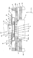
- FIG. 3A is a plan view showing the configuration of the reticle stage
- FIG. 3B is a longitudinal sectional view of the reticle stage device taken along line BB in FIG. 3A.
- FIG. 2 is a longitudinal sectional view showing the vicinity of a reticle stage device of the exposure apparatus of FIG. 1. It is a figure for demonstrating the structure of a reticle encoder system.
- FIG. 2 is a block diagram showing an input / output relationship of a main controller that mainly constitutes a control system of the exposure apparatus of FIG. 1.
- FIG. 8 is a longitudinal sectional view showing the vicinity of a reticle stage device of the exposure apparatus of FIG. 7.
- FIG. 8 is a block diagram which shows the input / output relationship of the main controller which mainly comprises the control system of the exposure apparatus of FIG.
- FIG. 1 shows a schematic configuration of an exposure apparatus 100 according to the first embodiment.
- the exposure apparatus 100 is a step-and-scan projection exposure apparatus, a so-called scanning stepper (also called a scanner).
- a projection optical system PL is provided, and in the following, the reticle R is set in the Z-axis direction in a direction parallel to the optical axis AX of the projection optical system PL and in a plane perpendicular to the Z-axis direction.
- a direction in which the wafer W and the wafer W are relatively scanned is a Y-axis direction
- a direction orthogonal to the Z-axis and the Y-axis is an X-axis direction
- rotation (tilt) directions around the X-axis, Y-axis, and Z-axis are ⁇ x
- the description will be made with the ⁇ y and ⁇ z directions.
- the exposure apparatus 100 includes an illumination unit IOP, a reticle stage apparatus 20 that includes a reticle stage RST that holds a reticle R and moves in a plane parallel to the XY plane, a projection optical system PL, and a wafer that drives the wafer W in the XY two-dimensional direction.
- a stage WST, a control system thereof, and a column 34 for holding the reticle stage device 20 and the projection optical system PL are provided.
- the illumination unit IOP includes a light source and an illumination optical system, and illuminates light (exposure light) IL in a rectangular or arcuate illumination area defined by a field stop (also referred to as a mask king blade or a reticle blind) disposed therein.
- the reticle R on which the circuit pattern is formed is illuminated with uniform illuminance.
- An illumination system similar to the illumination unit IOP is disclosed in, for example, US Pat. No. 5,534,970.
- ArF excimer laser light (wavelength 193 nm) is used as the illumination light IL.
- a part of the illumination light IL is extracted by a beam splitter disposed inside the illumination optical system, and an illuminance signal from a power monitor, also called an integrator sensor, is sent to the main controller 50.
- Reticle stage apparatus 20 surrounds reticle stage surface plate RBS arranged substantially in parallel at a predetermined interval below illumination unit IOP, reticle stage RST arranged on reticle stage surface plate RBS, and reticle stage RST.
- a counter mass 18 made of a frame-like member arranged on the reticle stage surface plate RBS, a reticle stage drive system 340 (see FIG. 6) for driving the reticle stage RST, and the like are provided.
- the reticle stage surface plate RBS has a plurality of (for example, three) anti-vibration units 14 on the top plate portion 32a of the column 34 (the anti-vibration units on the back side in FIG. 1 are not shown). It is supported substantially horizontally through.
- Reticle stage RST is arranged on reticle stage surface plate RBS, and reticle R is held on reticle stage RST. The specific configuration of reticle stage device 20 will be described in detail later.
- the projection optical system PL for example, a refractive optical system including a plurality of optical elements (lens elements) arranged along an optical axis AX parallel to the Z-axis direction is used.
- the projection optical system PL is, for example, both-side telecentric and has a predetermined projection magnification (for example, 1/4 or 1/5). For this reason, when the illumination area is illuminated by the illumination light IL from the illumination unit IOP, the illumination light that has passed through the reticle R arranged so that the first surface (object surface) and the pattern surface of the projection optical system PL substantially coincide with each other.
- a reduced image of the circuit pattern of the reticle in the illumination area is arranged on the second surface (image surface) side of the projection optical system PL via the projection optical system PL.
- a region (exposure region) conjugated to the illumination region on the wafer W having a resist (sensitive agent) coated on the surface thereof is formed.
- the reticle stage RST and wafer stage WST are driven synchronously to move the reticle relative to the illumination area (illumination light IL) in the scanning direction (Y-axis direction) and to the exposure area (illumination light IL).
- the wafer W By relatively moving the wafer W in the scanning direction (Y-axis direction), scanning exposure of one shot area (partition area) on the wafer W is performed, and a reticle pattern is transferred to the shot area. That is, in the present embodiment, the pattern of the reticle R is generated on the wafer W by the illumination unit IOP and the projection optical system PL, and the sensitive layer (resist layer) on the wafer W is exposed on the wafer W by the illumination light IL. That pattern is formed.
- a flange FLG is provided at substantially the center in the height direction of the lens barrel of the projection optical system PL.
- the column 34 is substantially horizontal by a plurality of (for example, three) leg portions 32b (not shown in FIG. 1) and the three leg portions 32b. And a top plate portion 32a supported by the head. An opening 34a penetrating in the vertical direction (Z-axis direction) is formed at the center of the top plate portion 32a. The upper end of the projection optical system PL is inserted into the opening 34a.
- Each of the three suspension support mechanisms 137 includes, for example, a coil spring 136 and a wire 135 which are connecting members having a flexible structure. Since the coil spring 136 vibrates like a pendulum in a direction perpendicular to the optical axis (Z axis) of the projection optical system PL, the vibration isolation performance in the direction perpendicular to the optical axis of the projection optical system PL (floor vibration is reduced).
- the projection optical system PL may be supported by the leg portion 32b of the column 34 via, for example, the flange FLG without being suspended and supported. Further, the projection optical system PL is placed on a support member (frame member) called, for example, a lens barrel surface plate or a metrology frame via the flange FLG, and this support member is suspended and supported on the top plate portion 32a. Or you may support by the leg part 32b of the column 34.
- frame member called, for example, a lens barrel surface plate or a metrology frame via the flange FLG
- a drive system 440 is provided.
- the drive system 440 includes, for example, a voice coil motor that drives the projection optical system PL in the radial direction of the lens barrel, and a voice coil motor that drives the projection optical system PL in the optical axis direction (Z-axis direction).
- the projection optical system PL can be displaced in the direction of six degrees of freedom by three drive systems 440 provided on the three legs 32b.
- the flange FLG of the projection optical system PL is provided with an acceleration sensor 234 (not shown in FIG. 1, refer to FIG. 6) for detecting the acceleration in the direction of 6 degrees of freedom of the projection optical system PL. Based on the detected acceleration information, main controller 50 (not shown in FIG. 1, refer to FIG. 6) causes drive system 440 so that projection optical system PL is stationary with respect to column 34 and floor F. Controls the driving of the voice coil motor. Note that another sensor such as a vibration sensor or a displacement sensor may be used instead of the acceleration sensor.
- a ring-shaped measurement mount 51 is suspended and supported via a plurality of (for example, three in this case) support members 53 (however, a support member on the back side of the paper surface is not shown).
- the three support members 53 are actually configured to include link members having flexure portions that can be displaced in directions of five degrees of freedom other than the longitudinal direction of the support member 53 at both ends thereof.
- the measurement mount 51 can be supported with almost no stress between it and the FLG.
- the measurement mount 51 includes a wafer interferometer 58, a wafer alignment system (hereinafter referred to as an alignment system) ALG (not shown in FIG. 1, refer to FIG. 6) as a mark detection system, and a multipoint focal position detection system (not shown). Etc. are held.
- an alignment system ALG for example, an image processing type FIA system disclosed in US Pat. No. 5,721,605 can be used.
- the multipoint focal position detection system for example, a multipoint focal position detection system disclosed in US Pat. No. 5,448,332 can be used.
- the interferometer 58, the wafer alignment system ALG, or the like is used with the above-described support member without providing the measurement mount 51. May be held.
- Wafer stage WST is levitated and supported on the upper surface of stage surface plate BS arranged horizontally below projection optical system PL via an air bearing or the like provided on the bottom surface.
- the stage surface plate BS is directly installed on the floor surface F, and the surface (upper surface) on the + Z side is processed so as to have a very high flatness, and the wafer stage WST.
- the movement reference plane (guide plane).
- the stage surface plate BS may be placed on the floor surface F via a plurality of vibration isolation mechanisms.
- Wafer stage WST holds wafer W by vacuum suction or the like via wafer holder 125, and stage controller BS by main controller 50 via wafer stage drive system 122 (not shown in FIG. 1, refer to FIG. 6). It can be driven freely in the XY plane along the upper surface.
- a planar motor may be used as wafer stage drive system 122.
- wafer stage WST may be supported by being floated on stage surface plate BS by magnetic force.
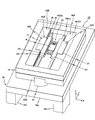
- FIG. 2 is a perspective view showing the external appearance of the reticle stage device 20.
- Reticle stage surface plate RBS is formed of a substantially rectangular plate-like member in plan view (viewed from above), and has an opening RBSa (see FIGS. 1 and 3B, etc.) serving as a path for illumination light IL at the center. ) Is formed.
- the opening RBSa is in communication with the opening 34a of the top plate portion 32a described above in the Z-axis direction.
- convex portions RBSb and RBSc extend in the Y-axis direction at positions on the upper surface of reticle stage surface plate RBS that are equidistant from the center in the ⁇ X direction and the + X direction. ing.
- the upper surfaces (surfaces on the + Z side) of the convex portions RBSb and RBSc are processed so that the flatness is very high, and a guide surface is formed when the reticle stage RST is moved.
- a plurality of air pads are fixed at predetermined intervals in the vicinity of the outer peripheral portion of the upper surface of the reticle stage surface plate RBS.
- Counter mass 18 on the plurality of air pads are arranged. Some of these air pads, for example, air pads at the four corners of reticle stage surface plate RBS, support the weight of counter mass 18 on the upper surface (+ Z side surface) of reticle stage surface plate RBS in a non-contact manner. Yes.
- the remaining air pads can adjust the balance between the vacuum suction force and the blowing pressure, and maintain a predetermined distance between the lower surface of the counter mass 18 and the upper surface of the reticle stage surface plate RBS.
- a plurality of (for example, three) anti-vibration units 14 shown in FIG. 1 provided between the reticle stage surface plate RBS and the top plate portion 32a each have a mechanical damper such as an air damper or a hydraulic damper. Contains. With this vibration isolation unit 14, it is possible to avoid transmission of relatively high frequency vibrations to the reticle stage RST by, for example, an air damper or a hydraulic damper. Further, between the reticle stage surface plate RBS and the top plate portion 32a, an X voice coil motor 66X that applies a driving force in the X-axis direction to the reticle stage surface plate RBS, and a Y voice that applies a driving force in the Y-axis direction. A coil motor 66Y and a Z voice coil motor 66Z (both not shown in FIG. 2, see FIG. 6) for applying a driving force in the Z-axis direction are provided.
- a mechanical damper such as an air damper or a hydraulic damper.
- At least one of the X voice coil motor 66X and the Y voice coil motor 66Y and two Z voice coil motors 66Z can be provided. That is, by providing at least one of the X voice coil motor 66X and the Y voice coil motor 66Y, the reticle stage surface plate RBS can be finely driven not only in the X axis direction and the Y axis direction but also in the ⁇ z direction. In addition, by providing three Z voice coil motors 66Z, the reticle stage surface plate RBS can be moved minutely not only in the Z-axis direction but also in the ⁇ x direction and the ⁇ y direction.
- the reticle stage surface plate RBS can be minutely driven in the direction of 6 degrees of freedom by the voice coil motors 66X, 66Y, and 66Z.
- the position of reticle stage surface plate RBS is measured with surface optical interferometer 240 and Z encoder 81 (both see FIG. 6) based on projection optical system PL.
- the three Z voice coil motors 66Z are provided at three positions not on a straight line between the reticle stage surface plate RBS and the top plate portion 32a.
- a plurality of deformation suppressing members (such as a voice coil motor) may be arranged between the reticle stage surface plate RBS and the top plate portion 32a.
- the main controller 50 changes the plurality of deformations according to the thrust generated by the three Z voice coil motors 66Z.
- the reticle stage surface plate RBS can be driven (displaced) in the Z, ⁇ x, and ⁇ y directions with its deformation suppressed as much as possible. .
- reticle stage RST includes reticle stage main body 22 and a pair of stators 40 ⁇ / b> A and 40 ⁇ / b> B fixed to both ends of reticle stage main body 22 in the X-axis direction.
- the reticle stage main body 22 as shown enlarged in FIG. 3 (A), planar view (when viewed from above) and a rectangular plate-like portion 22 0, respectively secured to the ⁇ X end of the plate-like portion 22 0
- the air slider portions 22 1 and 22 2 have a rectangular parallelepiped shape with the Y-axis direction as a longitudinal direction.
- the approximate center of the plate-like portion 22 0, the opening 22a as the passage of the illumination light IL is formed.
- a pair of vacuum chucks 95, 96 for attracting and holding the back surface of the reticle R is arranged.
- a pair of stoppers (positioning member) 93 and 94 are fixed on the -Y side of the portion of the plate-like portion 22 0 upper surface of the opening 22a. These stoppers 93 and 94 abut against the ⁇ Y side end face (side face) of the reticle R to position the reticle R.
- the clamper (pressing members) 91 and 92 consisting of a pair of pivot arms are attached.
- the clampers 91 and 92 form a pair with stoppers 93 and 94, respectively, and constitute clamp devices that hold the reticle R from one side and the other side in the Y-axis direction.
- One of the clamper 91, and the X-axis direction is the longitudinal direction, and pivotally attached to the plate-like portion 22 0 that -X end as a fulcrum (center of rotation). Further, a substantially hemispherical convex portion is provided opposite to the stopper 93 at the + X end portion of the ⁇ Y side surface of the clamper 91.
- the clamper 91 is always urged clockwise by an urging member such as a spring spring (not shown) so that the convex portion comes into pressure contact with the + Y side end surface of the reticle R.
- the other clamper 92 is configured in the same manner as the clamper 91 although it is symmetrical.
- the reticle R is placed on the plate-like portion 22 0 (reticle stage RST) in a state of closing the opening 22a from above.
- the reticle R is positioned with its ⁇ Y side surface coming into contact with the stoppers 93 and 94, and is fixed by a predetermined pressing force applied to the + Y side surface by the clampers 91 and 92. After the reticle R is fixed by the clampers 91 and 92 and the stoppers 93 and 94 in this way, both ends of the lower surface in the X-axis direction are sucked by the vacuum chucks 95 and 96.
- the clampers 91 and 92 are separated from the reticle R against the urging force.
- the upper surface pattern of the reticle R with a sucker or the like from above. Pick up and lift the surface opposite the surface.
- the outside of the pattern area of the reticle R is hooked with a hook or the like and lifted.
- the reticle R may be temporarily lifted from below by a vertically moving member and transferred from the vertically moving member to the transfer arm.
- an actuator for example, a motor or an air cylinder
- an actuator for example, a motor or an air cylinder
- a rotation type but a slide-type clamper can also be used.
- reticle fiducial mark plates (hereinafter abbreviated as “reticle mark plates”) LF1, LF2 on which aerial image measurement reference marks are formed are aligned with reticle R. are arranged, it is fixed to the plate-like portion 22 0.
- the reticle mark plates LF1 and LF2 are made of the same glass material as that of the reticle R, for example, synthetic quartz, fluorite, lithium fluoride, or other fluoride crystals. Details of the reticle mark plate are disclosed in, for example, US Patent Application Publication No. 2002/0041377.
- the reticle R has an XY plane whose pattern surface (lower surface) passes through the neutral surface of the reticle stage main body 22 (reticle stage RST) (the center of gravity of the reticle stage main body 22). (A plane parallel to the surface).
- the air slider portions 22 1 and 22 2 are lattice-shaped ribs for maintaining strength inside the air slider portion 22 1 as shown in FIG. And a hollow member having an inner space defined by the lattice-like ribs.
- the air slider portions 22 1 and 22 2 are formed of a rectangular parallelepiped member that is thinned so that only the rib portion remains in order to reduce the weight.
- the outer half of the bottom surface of the air slider portions 22 1 and 22 2 in the X-axis direction that is, the portion of the reticle stage surface plate RBS facing the above-described convex portions RBSc and RBSb as shown in FIG.
- the air supply groove and a pair of exhaust grooves (both not shown) on both sides in the X-axis direction of the air supply groove are formed over the entire length in the Y-axis direction.
- the air supply groove includes a trunk groove extending in the Y-axis direction, a plurality of T-shaped surface throttle grooves that are in communication with both sides of the trunk groove in the X-axis direction and are formed at predetermined intervals in the Y-axis direction, have.
- the reticle stage surface plate RBS is formed with an air supply port and a pair of exhaust ports on the upper surfaces of the convex portions RBSc and RBSb, respectively, facing at least a part of each of the air supply groove and the pair of exhaust grooves.
- a so-called surface plate supply type differential exhaust type static gas bearing is used. Details of the platen supply type differential exhaust type static gas bearing are disclosed in detail in, for example, US Pat. No. 7,489,389.
- the convex shape is formed by the balance between the static pressure of the pressurized gas supplied through the air supply port and sprayed from the surface throttle groove to the upper surfaces of the convex portions RBSc and RBSb and the total weight of the reticle stage RST.
- the reticle stage RST is levitated and supported in a non-contact manner over the portions RBSc and RBSb via a clearance (interval / gap) of about several microns.
- the pressurized gas a rare gas such as clean dry air (CDA), nitrogen, or helium is used as the pressurized gas.
- the movers 30A and 30B are each constituted by a magnet unit containing a plurality of magnets arranged in a predetermined positional relationship. Each of the movers 30A and 30B is engaged with a pair of stators 40A and 40B as shown in FIG.
- one end of the stator 40A is fixed and supported at both ends in the longitudinal direction (Y-axis direction) on the + Y side inner surface and the ⁇ Y side inner surface of the counter mass 18, and in the longitudinal direction.
- One end portion (+ X end portion) in the direction orthogonal to the X axis direction (+ X end portion) is fixedly supported on one inner surface ( ⁇ X side inner surface) of the counter mass 18 on one side in the X axis direction.
- the other end of the other stator 40B in the longitudinal direction (Y-axis direction) is fixedly supported on the + Y side inner surface and the ⁇ Y side inner surface of the counter mass 18, and one end in the direction perpendicular to the longitudinal direction.
- the portion ( ⁇ X end portion) is fixedly supported on one inner surface (+ X side inner surface) of the counter mass 18 in the X-axis direction.
- the moving magnet type first that drives the reticle stage RST with a predetermined stroke in the Y-axis direction and also slightly moves in the X-axis direction by the stator 40A and the movable element 30A engaged therewith.
- An XY drive linear motor is configured.
- a moving magnet type second XY drive that drives the reticle stage RST with a predetermined stroke in the Y-axis direction and a minute drive in the X-axis direction by the stator 40B and the movable element 30B engaged therewith.
- a linear motor is configured. Then, by these first and second XY drive linear motors, the reticle stage drive system 340 (see FIG.
- Reticle stage drive system 340 drives the reticle stage within a neutral plane that includes the center of gravity of reticle stage RST.
- the main controller 50 controls the magnitude and direction of the current supplied to each coil constituting the reticle stage drive system 340.
- the reticle stage is not limited to the above-described configuration.
- the reticle stage surface plate RBS is fixed on the top plate portion 32a (via a vibration isolation unit) and moved thereon.
- the reticle stage may be constituted by a coarse / fine movement stage.
- a coarse movement stage that moves in each of the X-axis, Y-axis, and ⁇ z directions, and a fine movement stage that is arranged on the coarse movement stage and holds the reticle R, can be finely moved in the direction of 6 degrees of freedom.
- You may comprise by a fine movement stage. In this case, the position measurement of the reticle stage surface plate RBS is not required.
- an annular shape for fixing a light transmission window member for example, a glass plate or a lens
- a purge cover 80 is provided below the fixed member 90.
- Purge cover 80 is a rectangular cylindrical portion 82 1 elongated in the X-axis direction in a plan view, the flange portion 82 2 provided at the upper end of the cylindrical portion 82 1, + Y direction from the lower end of the cylindrical portion 82 1 And a pair of plate portions 82 3 and 82 4 respectively extending in the ⁇ Y direction.
- Flange portion 82 2 its upper surface is fixed to the lower surface of the fixed member 90.
- the cylindrical portion 82 1 surrounds the irradiation area of illumination light IL emitted from the illumination unit IOP.
- X-axis direction length of the cylindrical portion 82 1 is somewhat longer set than the distance in the X-axis direction between the outer edge of the air slider 22 1, 22 2 of the reticle stage RST.
- Plate portion 82 3 is a parallel plate-shaped portion to the XY plane extending from the lower end of the cylindrical portion 82 1 of the + Y side on the + Y side.
- the lower surface of the plate portion 82 3 is located slightly higher than the upper end surface of the reticle stage RST.
- Plate portion 82 4 is a parallel plate-shaped portion to the XY plane extending toward the -Y side from the lower end of the cylindrical portion 82 1 of the -Y side.
- the lower surface of the plate portion 82 4 are located in the plate portion 82 3 of the lower surface on the same plane.
- the end cover 23 1 covers the + Y end of the end surface and the upper surface of the air slider 22 1, 22 2 of the + Y side (including the space between the air slider 22 1, 22 2), the end cover 23 2 covers the air slider section 22 1, 22 end face of the second -Y side and -Y ends of the upper surface (including the space between the air slider 22 1, 22 2).
- the space in which the reticle R is placed is surrounded by the end covers 23 1 and 23 2 and the air slider portions 22 1 and 22 2 in the four directions of front, rear, left and right.
- each predetermined clearance (gap / Clearance / gap (gap) / space distance), for example, a clearance (gap / interval / gap (space) / space distance) of several ⁇ m to several mm (3 mm at the maximum) is formed.
- Plate portion 82 3, 82 4 of the length of the X-axis direction is the cylindrical portion 82 1 of the X-axis direction length equal to or slightly shorter setting. Further, the plate portion 82 3, as in the moving range in the Y-axis direction during scanning exposure of the reticle stage RST, regardless of its position, its lower surface may at least partially opposed to the end cover 23 1, The length in the Y-axis direction is set. Similarly, the plate portion 82 4, within the moving range in the Y-axis direction during scanning exposure of the reticle stage RST, regardless of its position, so that the lower surface may at least partially opposed to the end cover 23 2 The length in the Y-axis direction and the installation position are set.
- the purge cover 80, the end covers 23 1 and 23 2 , the air slider portions 22 1 and 22 2, and the reticle R form a substantially airtight space 181.
- this space 181 for example, clean dry air (CDA) is supplied as a purge gas from a supply port (not shown) and exhausted to the outside through an exhaust port (not shown). That is, the internal gas (air) in the space 181 is purged with CDA.
- CDA the proportion of water vapor, which is a haze generation reaction acceleration substance, in the reticle (mask) is extremely smaller than that of normal air. In this embodiment, for example, the humidity is about 1% or less.
- the space 181 is a substantially airtight purge chamber.
- this space is referred to as a first purge space 181.
- the first purge space 181 is in a state where the control accuracy of the internal humidity can be maintained at a predetermined level. For example, when the inside is purged with a CDA of 1%, the humidity is reduced to about 2%. It is airtight enough to maintain. Further, the first purge space 181 can suppress the occurrence of fogging of an optical member such as a lens of an illumination unit in contact with the space 181 due to the presence of water vapor. For example, the first purge space 181 can be suppressed to such an extent that it does not hinder exposure. It is airtight.
- a seal is made via a labyrinth seal LB which is a kind of non-contact seal.
- the labyrinth seal LB shown in FIG. 3B is attached between the reticle stage surface plate RBS and the projection optical system PL so as to surround the opening RBSa.
- the labyrinth seal LB is engaged with the upper member having a top end fixed to the lower surface of the reticle stage surface plate RBS in a state of surrounding the periphery of the opening RBSa without contact with the upper member.
- the lower surface of the projection optical system PL is fixed to the upper surface of the projection optical system PL.
- the upper member is concentric as viewed from the ⁇ Z direction and has multiple protrusions
- the lower member is located slightly outside the upper member and is concentric as viewed from the + Z direction and engages the upper member in a non-contact manner. And has multiple protrusions.
- the two protrusions are always in non-contact engagement without contacting each other even when the reticle stage surface plate RBS is finely driven.
- the reticle R and the reticle stage main body 22 the inner wall surface of the opening of the reticle stage surface plate RBS, the upper surface of the projection optical system PL, the labyrinth seal
- a substantially airtight space 182 partitioned by LB is formed.
- CDA is supplied into the space 182 from a blowout port 192 provided in a part of the inner wall surface of the opening of the reticle stage surface plate RBS, and is exhausted to the outside through an exhaust port (not shown). That is, the internal gas (air) in the space 182 is purged with CDA.
- the space 182 is a substantially airtight purge chamber. In the following, it referred to as the space between the second purge space 182.
- the second purge space 182 is also set in an airtight state comparable to the first purge space 181 described above.
- the gratings RG1 and RG2 extend over almost the entire length in the Y-axis direction on the bottom surfaces of the air slider portions 22 1 and 22 2 (see FIG. 5). .
- a two-dimensional grating having a periodic direction in the X-axis direction and the Y-axis direction is formed on each surface of the gratings RG1 and RG2.
- a hexagonal upper surface member 60 having a rectangular opening PLa formed in the center as shown in FIG. 5 is fixed (see FIG. 3B).
- the opening PLa is an optical path (passage) of the illumination light IL that passes through the pattern surface of the reticle R and passes through the opening RBSa of the reticle stage surface plate RBS.
- Three encoder heads 72, 73, 74 and 77, 78, 79 are fixed to both ends of the upper surface of the upper surface member 60 in the X-axis direction (both sides of the opening PLa).
- the encoder heads 72 and 77 are near the + Y side corner of the aperture PLa, the encoder heads 74 and 79 are near the ⁇ Y side corner, and the encoder heads 73 and 78 are the center of the aperture PLa (that is, the light of the projection optical system PL). It is arranged at the same Y position as (axis).
- the three encoder heads 72, 73, 74 and 77, 78, 79 are opposed to the gratings RG1, RG2, respectively.
- the encoder heads 72 to 74 and 77 to 79 have two measurement directions, ie, one direction parallel to the grating (measurement surface) (one period direction of the grating) and a direction perpendicular to the measurement surface.
- a two-dimensional encoder head is employed.
- An example of such a head is disclosed in, for example, US Pat. No. 7,561,280.
- the four encoder heads 72, 74, 77, and 79 have the Y-axis direction and the Z-axis direction as measurement directions, and the two encoder heads 73 and 78 have the X-axis direction and Z-axis direction as measurement directions.
- the encoder heads 72, 73, 74 are provided with a measurement beam on the grating RG1 on the bottom surface of the reticle stage RST (air slider portion 22 1 ) through the opening RBSa of the reticle stage surface plate RBS. Is received from below, and a plurality of diffracted lights generated by the grating RG1 are received, and position information of the grating RG1 (that is, the air slider portion 22 1 of the reticle stage RST) in each measurement direction is obtained (measured).
- the coherent measurement beam is irradiated (incident) so that the gratings RG1 and RG2 are irradiated in both the X-axis direction and the Y-axis direction.
- Diffracted light is generated at a plurality of angles (diffraction angles). Therefore, the encoder heads 72 and 74 receive a plurality of diffracted lights generated in the Y-axis direction, and the grating RG1 (that is, the reticle stage) in the Y-axis direction and the Z-axis direction with the irradiation point of each measurement beam as the measurement point.
- the position information of the air slider portion 22 1 ) of the RST is obtained (measured).
- the encoder head 73 receives a plurality of diffracted lights generated in the X-axis direction, and uses the measurement beam irradiation point as a measurement point to measure the grating RG1 in the X-axis direction and the Z-axis direction (that is, the air slider portion 22 of the reticle stage RST). 1 ) The position information of 1 ) is obtained (measured).
- the encoder heads 72, 73, 74 obtain (measure) position information regarding the X-axis direction, the Y-axis direction, and the Z-axis direction of the reticle stage RST, and a first encoder system 71 having six degrees of freedom in measurement (FIG. 6). Reference) is configured. Measurement information of the first encoder system 71 (encoder heads 72, 73, 74) is sent to the main controller 50 (see FIG. 6).
- the encoder heads 77, 78, 79 are connected to the grating RG 2 on the bottom surface of the reticle stage RST (air slider portion 22 2 ) through the opening RBSa of the reticle stage surface plate RBS, similarly to the encoder heads 72, 73, 74 described above.
- a measurement beam is irradiated from below, and a plurality of diffracted lights generated by the grating RG2 are received, and position information of the grating RG2 (that is, the air slider portion 22 2 of the reticle stage RST) in each measurement direction is obtained (measured). ).
- the encoder heads 77 and 79 receive a plurality of diffracted lights generated in the Y-axis direction, and the grating RG2 (that is, the reticle) in the Y-axis direction and the Z-axis direction with the irradiation point of each measurement beam as the measurement point.
- Position information of the air slider portion 22 2 ) of the stage RST is obtained (measured).
- the encoder head 78 receives a plurality of diffracted lights generated in the X-axis direction, and uses the measurement beam irradiation point as a measurement point to measure the grating RG2 in the X-axis direction and the Z-axis direction (that is, the air slider portion 22 of the reticle stage RST). 2 ) Find (measure) position information.
- the encoder head 77, 78, 79 obtains (measures) position information regarding the X-axis direction, the Y-axis direction, and the Z-axis direction of the reticle stage RST, and a second encoder system 76 with six degrees of freedom in measurement (FIG. 6). Reference) is configured.
- Measurement information of the second encoder system 76 is sent to the main controller 50 (see FIG. 6).
- Main controller 50 has a reticle stage with reference to the center (optical axis) of projection optical system PL based on the measurement information of first and second encoder systems 71 and 76 (encoder heads 72 to 74, 77 to 79). Obtain (calculate) position information regarding the 6-degree-of-freedom direction of RST.
- a reticle encoder system 70 is configured including the first and second encoder systems 71 and 76 (see FIG. 6).
- main controller 50 for example, an average air slider section 22 1 of the Y position of reticle stage RST from the measurement values of the position of the measured Y-axis direction by the encoder heads 72, 74 (Y 1), the encoder X position of the air slider 22 reticle stage RST from the measurement values of the position of the measured X-axis direction by the head 73 seek (X 1).
- main controller 50 obtains the average air slider section 22 2 of the Y position of reticle stage RST from the measurement values of the position of the the Y-axis direction measured by the encoder heads 77, 79 (Y 2), the encoder head 78 X position of the air slider 22 2 of the reticle stage RST from the measurement values of the position of the measured X-axis direction determine the (X 2). Further, main controller 50, than the average and the difference between Y 1 and Y 2, respectively, Y position and [theta] z position of the reticle stage RST ([theta] z direction rotation amount, i.e. yawing amount) sought, the X 1 and X 2 The X position of reticle stage RST is obtained from the average.
- main controller 50 determines the Z position and ⁇ y position (rotation amount in the ⁇ y direction, that is, rolling in the ⁇ y direction) of reticle stage RST from the average and difference of the measured values of the position in the Z-axis direction measured by encoder heads 73 and 78, respectively. (Quantity).
- the ⁇ x positions ( ⁇ x 1 , ⁇ x 2 ) of the air slider portions 22 1 and 22 2 are obtained from the difference between the measured values of the positions in the Z-axis direction measured by the encoder heads 72, 74 and 77, 79, respectively, and ⁇ x 1 and the average [theta] x position of the reticle stage RST from the [theta] x 2 ([theta] x direction rotation amount, i.e. pitching amount) is determined.
- the X, Y, Z, and ⁇ x positions of the reticle stage RST are obtained by averaging any two measured values in the above-described directions measured by the encoder system 70, and using any one of the measured values as they are. Also good.
- Main controller 50 drives (positions control) reticle stage RST via reticle stage drive system 340 described above based on the position information about the six degrees of freedom direction of reticle stage RST obtained as described above. .
- FIG. 6 is a block diagram showing the input / output relationship of the main controller 50 that mainly constitutes the control system of the exposure apparatus 100 of the present embodiment.
- the main controller 50 includes a so-called microcomputer (or workstation) comprising a CPU (Central Processing Unit), ROM (Read Only Memory), RAM (Random Access Memory), etc., and controls the entire apparatus. Control.
- microcomputer or workstation
- CPU Central Processing Unit
- ROM Read Only Memory
- RAM Random Access Memory
- a reticle loader (not shown) loads the reticle R onto the reticle stage RST, and a wafer loader (not shown) loads the wafer W onto the wafer stage WST.
- an alignment system ALG see FIG. 6
- a reticle alignment system (not shown), etc., for example, according to a predetermined procedure disclosed in US Pat. No. 5,646,413, the reticle alignment and alignment system ALG Preparatory work such as baseline measurement is performed.
- reticle alignment may be performed using an aerial image measuring instrument (not shown) provided on wafer stage WST.
- the main controller 50 executes wafer alignment such as EGA (Enhanced Global Alignment) disclosed in, for example, US Pat. No. 4,780,617 using the alignment system ALG, and the wafer alignment. After completion of the exposure operation by the step-and-scan method is performed. Since this exposure operation is the same as the conventional step-and-scan method, its detailed description is omitted.
- EGA Enhanced Global Alignment
- the wafer stage WST and the reticle stage RST are relatively driven in the Y-axis direction under the control of the main controller 50.
- the main controller 50 performs the measurement of the reticle encoder system 70.
- reticle stage drive system 340 is controlled to drive reticle stage RST.
- the reticle stage RST reciprocates in a predetermined range sandwiching the illumination area with respect to the Y-axis direction. By this movement, the airtight state is maintained not only in the purge space 182 but also in the purge space 181, and the CDA purge is performed. Is done effectively.
- main controller 50 controls X voice coil motor 66X and Y voice coil motor 66Y described above based on the measurement result of surface plate interferometer 240 so that reticle stage surface plate RBS maintains a predetermined state.
- the Z voice coil motor 66Z is controlled based on the measurement result of the Z encoder 81 to adjust the position of the reticle stage surface plate RBS in the Z direction and the ⁇ x and ⁇ y directions, thereby indirectly adjusting the Z direction of the reticle R and The position in the ⁇ x and ⁇ y directions is adjusted.
- the exposure apparatus 100 of the present embodiment is arranged away from the scanning direction (Y-axis direction) of the reticle stage RST, one end is connected to the illumination unit IOP, and the other end is the reticle stage RST and the reticle R.
- Clearance (gap / interval / gap (gap) / space) of about several ⁇ m to several mm on one surface (upper surface) of + Z side (illumination unit IOP side), more precisely, the upper surface of the end covers 23 1 , 23 2
- a purge cover 80 having a pair of plate portions 82 3 and 82 4 that are opposed to each other at a distance) is provided.
- a minute clearance (gap / interval / gap (gap) / space distance) is set between the reticle stage RST and the pair of plate portions 82 3 and 82 4 so as to substantially prevent the gas flow. ing.
- the substantially airtight space 181 including the optical path of the illumination light IL between the illumination unit IOP and the projection optical system PL, which is surrounded by the purge cover 80, the reticle stage RST and / or the reticle R. Is formed. Therefore, by making this space 181 a purge space purged by, for example, CDA, it is not necessary to surround the reticle stage device 20 holding the reticle R with a large airtight shielding container.
- the substantially airtight space is a space purged by CDA, haze of the mask can be effectively prevented.
- the purge cover 80 also serves as a partition that isolates the purge space 181 from the outside air, a space for purging can be secured without making the apparatus unnecessarily large.
- haze of the reticle R can be effectively prevented, pattern defects and CD (Critical) caused by transfer of the haze grown on the reticle onto the wafer. Dimension) can be prevented from occurring. Further, since it is not necessary to frequently inspect the reticle in order to prevent these defects, it is possible to prevent a decrease in productivity and consequently improve productivity.
- FIG. 7 schematically shows a configuration of an exposure apparatus 1000 according to the second embodiment.
- FIG. 9 is a block diagram showing the input / output relationship of the main controller 50 that mainly constitutes the control system of the exposure apparatus 1000 of the second embodiment.
- the exposure apparatus 1000 of the second embodiment is basically configured in the same manner as the exposure apparatus 100 of the first embodiment described above.
- the difference from the exposure apparatus 100 of the first embodiment is that a reticle stage apparatus 20 ′ is provided instead of the reticle stage apparatus 20.
- the reticle stage apparatus 20 ' is different from the reticle stage apparatus 20 described above in that it includes a pair of proximity cooling devices 110A and 110B.
- proximity cooling devices 110A and 110B will be described and the differences from the first embodiment will be mainly described.
- the proximity cooling devices 110A and 110B have a thin plate shape, and one of the proximity cooling devices 110A includes a purge cover 80 configured in the same manner as the purge cover of the first embodiment, as shown in FIG. the lower surface of the plate portion 82 3, and is fixed.
- the lower surface of the proximity cooling device 110A is positioned slightly higher than the upper end surface of the reticle stage RST.
- the other proximity cooling device 110B is a lower surface of the plate portion 82 4 of the purge cover 80 is fixed.
- the lower surface of the proximity cooling device 110B is located on the same plane as the lower surface of the proximity cooling device 110A.
- the proximity between the lower surface and the end cover 23 1 cooling device 110A, and between the adjacent cooling device 110B of the lower surface and the end cover 23 2 each predetermined clearance (gap / A clearance (gap / gap / gap / space distance) of several ⁇ m to several mm (maximum 3 mm), for example, is formed.
- proximity cooling device 110A, the Y-axis direction length of 110B in this embodiment, has substantially the same length as the plate portion 82 3, 82 4.
- the proximity cooling device 110A, Y-axis direction length of 110B is the plate portion 82 3, 82 4 and may not be substantially the same.
- Proximity cooling device 110A as in the moving range in the Y-axis directions during the scanning exposure of the reticle stage RST, regardless of its position, its lower surface may at least partially opposite to the end cover 23 1, the The length in the Y-axis direction is set.
- proximity cooling device 110 ⁇ / b > B can have its lower surface at least partially opposed to end cover 232 regardless of its position within the movement range of reticle stage RST in the Y-axis direction during scanning exposure.
- the length in the Y-axis direction and the installation position are set.
- the cooling regions by the proximity cooling devices 110A and 110B are set on one side and the other side in the Y-axis direction across the irradiation region of the illumination light IL emitted from the illumination unit IOP.
- the purge cover 80, the proximity cooling devices 110A and 110B, the end covers 23 1 and 23 2 , the air slider portions 22 1 and 22 2, and the reticle R are substantially airtight.
- a purge space 181, that is, a purge chamber in an almost airtight state is formed.
- the inside of the first purge space 181 is purged with clean dry air (CDA) having a humidity of 1% or less, for example.
- CDA clean dry air
- the proximity cooling devices 110A and 110B are cooled by heat exchange with a refrigerant passing through the inside of a cooling pipe (not shown).
- the temperatures of the proximity cooling devices 110A and 110B are monitored by a temperature sensor (not shown), and the temperature signal is transmitted to the temperature controller 28 (see FIG. 9) so as to be controlled to a target value as described later. It has become.
- the temperature control of the proximity cooling devices 110A and 110B can be achieved by changing the temperature of the refrigerant.
- a semiconductor Peltier element (not shown) is installed between the proximity cooling devices 110A and 110B and the refrigerant, and a current flowing therethrough is changed. This can also be achieved by actively controlling the amount of heat transfer. In the latter case, there is an advantage that the temperature control response of the proximity cooling devices 110A and 110B is accelerated.
- the configuration of other parts of the exposure apparatus 1000 of the second embodiment is the same as that of the exposure apparatus of the first embodiment described above.
- the main controller 50 loads the reticle R onto the reticle stage RST and loads the wafer W onto the wafer stage WST, as in the first embodiment.
- wafer alignment such as EGA is performed, and after the wafer alignment is completed, a step-and-scan exposure operation is performed.
- the wafer stage WST and the reticle stage RST are relatively driven in the Y-axis direction under the control of the main controller 50.
- the main controller 50 performs the measurement of the reticle encoder system 70.
- reticle stage drive system 340 is controlled to drive reticle stage RST.
- reticle stage RST reciprocates in a predetermined range in the Y-axis direction across the illumination area (a range that can be opposed to almost the entire surface of the pair of proximity cooling devices 110A and 110B).
- the purge space 181 the airtight state is maintained, and the CDA purge is effectively performed.
- the temperature control device controller 28 efficiently and efficiently passes the reticle R and the reticle R through the pair of proximity cooling devices 110A and 110B provided apart in the Y-axis direction. Reticle stage RST is cooled.
- the proximity cooling devices 110A and 110B cool the reticle R and the reticle stage RST in a non-contact manner. That is, cooling is performed by radiant heat transfer.
- the proximity cooling device may be set at a lower temperature than the reticle R.
- the amount of radiant heat transfer from the high temperature object A to the low temperature object B is determined according to the following equation (1) (for example, see Hallman's "Heat Transfer Engineering" (Brain book)).
- the main controller 50 may adjust the temperature of the proximity cooling device via the temperature controller 28 so that the reticle R reaches a desired temperature based on the equation (1).
- q the amount of heat transferred by radiation from the object A to B sigma: Boltzmann constant TA: absolute temperature of the object A TB: absolute temperature of the object B epsilon A: emissivity of the object A epsilon B: object B emissivity S A : Surface area of object A S B : Surface area of object B F AB : Form factor from object A to B
- the form factor in the above formula (1) is a number of 1 or less, but between rectangular flat plates as in this embodiment In the case of heat transfer, the value of the shape factor approaches 1 as the ratio of the length of the side of the rectangle to the distance between the flat plates increases.
- the illumination area of the reticle R is often slit-like as in this embodiment, and the proximity cooling devices 110A and 110B are considerably placed on the reticle R on the reticle R as shown in FIG.
- the proximity cooling devices 110A and 110B are always relative to an area of about 2/3 with respect to the entire area of the reticle R, regardless of the position of the reticle stage RST in the scanning range. It is possible. Therefore, the form factor can be easily set to a value of about 0.2.
- Main controller 50 calculates an exposure time ratio (on / off duty ratio of irradiation (pulse)) based on the illuminance signal from the power monitor (integrator sensor) described above, the calculation result, known illuminance, and reticle R
- the exposure energy is calculated based on data such as the pattern aperture ratio and reflectance, and the amount of heat Q given to the reticle R is predicted based on the calculation result.
- the main controller 50 uses the above equation to change the proximity cooling devices 110A and 110B so that the amount of heat Q coincides with the amount of heat q applied from the reticle R to the proximity cooling devices 110A and 110B during radiation cooling. Is determined, and the command value is transmitted to the temperature controller 28.
- the temperature of the proximity cooling devices 110A and 110B is controlled by the temperature controller 28 and adjusted so that the temperature of the reticle R is within a predetermined range.
- the exposure apparatus 1000 has the + Z side of the reticle stage RST and the reticle R (illumination unit IOP) in a region that does not block the illumination light IL between the illumination unit IOP and the reticle R.
- Proximity cooling devices 110A and 110B are arranged on one side of the surface facing each other with a predetermined clearance (gap / interval / gap (gap) / space distance).
- the space 181 including the optical path of the illumination light IL between the illumination unit IOP and the projection optical system PL is a first purge space purged with a purge gas, for example, CDA, and the proximity cooling devices 110A and 110B are the first ones.
- the proximity cooling devices 110A and 110B can perform temperature control (cooling) of the reticle R held on the reticle stage RST during the step-and-scan exposure operation.
- the proximity cooling devices 110A and 110B arranged on both sides in the Y-axis direction with respect to the illumination area are provided, so that the temperature distribution of the reticle R is also controlled, for example, the entire surface of the reticle R is uniform. It is also possible to control the temperature so that it becomes a proper temperature.
- the clearance (gap / interval / gap (gap) / space distance) between the reticle stage RST, more precisely, the end covers 23 1 , 23 2 and the proximity cooling devices 110A, 110B, and the gas flow are substantially reduced.
- the first purge space 181 in a substantially airtight state surrounded by the purge cover 80, the proximity cooling devices 110A and 110B, the reticle stage RST and / or the reticle R is set by setting the dimensions so as to prevent. Can produce. That is, it is not necessary to surround the reticle stage RST that holds the reticle R with a large airtight shielding container.
- the substantially airtight space is the first purge space 181 purged with the purge gas
- various merits according to the characteristics of the purge gas are produced.
- CDA is used as the purge gas
- haze of the reticle R can be effectively prevented.
- the proximity cooling devices 110A and 110B also serve as a part of the partition member that isolates the first purge space 181 from the outside air, the space in which the purge is performed is larger than necessary in this respect as well. It is possible to secure without making it.
- the temperature control (cooling) of the reticle R held on the reticle stage RST can be performed during the exposure operation of the step-and-scan method, so that the throughput is not reduced. Generation of pattern distortion caused by thermal expansion of the reticle can be suppressed, and as a result, improvement in overlay accuracy is expected. Further, since the reticle R is cooled by using the radiant heat transfer by the proximity cooling devices 110A and 110B, it is possible to suppress the occurrence of defective circuit elements such as rolling of particles (so-called dust) and adhesion of the particles to the reticle. can do.
- a radiation thermometer that measures the temperature of the reticle R
- the amount of heat given to the reticle R is predicted based on the temperature measured by the radiation thermometer (or cooling).
- the temperature of the device may be controlled).
- the method for controlling the cooling device is not limited to the above, and other methods may be used.
- the control pattern of the cooling device may be determined in advance, for example, by experiment or simulation without providing one or both of the temperature sensor that measures the temperature of the reticle R and the temperature sensor that monitors the temperature of the cooling device. .
- the opposing member in the first embodiment, the purge cover 80 is opposed to the reticle stage RST (including the end covers 23 1 and 23 2 ) via a predetermined gap.
- the distance is set to be slightly longer than or equal to the distance is described, this is only an example.
- the opposing member that faces the reticle stage RST (including the end covers 23 1 and 23 2 ) with a predetermined gap does not need to be a flat member, and the movement of the reticle stage during scanning exposure is not necessary. It is sufficient if there is a flat portion having a length in the X-axis direction in which the airtightness between the reticle stage RST and the reticle stage RST is substantially maintained during the movement. That is, the outer portion of the plane portion in the X-axis direction may be bent downward or upward, or may protrude.
- the upper surface of both outer portions in the X-axis direction of the reticle placement region of reticle stage RST is the upper surface of reticle R.
- the height of the same surface may be sufficient, and a different height may be sufficient.
- the reticle of the reticle stage RST is used.
- the opposing surface that opposes the upper surface of both outer portions in the X-axis direction of the mounting region with a predetermined gap is formed between the opposing member (in the first embodiment, the plate-like plate portion 82 3 of the purge cover 80, 82 4 , in the second embodiment, it is desirable to provide the proximity cooling device 110A, 110B).
- the reticle stage RST (including the end covers 23 1 and 23 2 ) has the upper surface of the reticle R during scanning exposure (during synchronous movement with the wafer stage WST). Z-axis as much as possible without contacting the opposing member (in the first embodiment, plate-like plate portions 82 3 , 82 4 of the purge cover 80, and in the second embodiment, the proximity cooling devices 110 A, 110 B). It is desirable to be close to the opposing member with respect to the direction. In particular, in the second embodiment, the cooling efficiency of reticle R (and reticle stage RST) by proximity cooling devices 110A and 110B is improved.
- the gap with the facing member is less than or equal to a certain level, it is possible to use not only a radiant heat transfer method but also a heat conduction type proximity cooling device as the proximity cooling device. Further, it is desirable that the rotation in the ⁇ x direction (that is, pitching) and the rotation in the ⁇ y direction (that is, rolling) are controlled so that reticle stage RST is as parallel as possible to the opposing member.
- the opposing surface portion (of the opposing member) is set by setting the length relationship and the positional relationship in the Y-axis direction between the reticle stage RST, the reticle R, and the opposing surface portion of the opposing member. for example, with respect to the plate portion 82 3, 82 4, the reticle stage RST only, the reticle stage RST and the reticle (or reticles only) may be opposed.
- the reticle stage RST between the opposing surface of the reticle R, and the opposing member also by the relationship of the X-axis direction length of and positioning of the relationship, the opposing surface of the opposing member (e.g., with respect to the plate portion 82 3, 82 4, the reticle stage RST only, the reticle stage RST and the reticle (or a reticle, Only) can be opposite.
- the measurement system that measures the position information of the reticle stage RST is not necessarily limited to the encoder system, and may be another measurement system such as an interferometer system.
- the proximity cooling devices 110A and 110B do not have to double as the partition walls of the purge space, and may not be used together with gas purge such as CDA in the reticle stage upper space.
- the proximity cooling devices 110A and 110B may be provided on both sides in the Y-axis direction of the illumination area and the irradiation area of the illumination light IL.
- the proximity cooling devices 110A and 110B may be provided only on one side.
- the size of the cooling surface of the proximity cooling devices 110A and 110B may be the same as that of the reticle or the pattern area thereof.
- the reticle stage RST can be moved to cool the reticle R against one of the proximity cooling devices.
- the cooling may be performed by bringing both closer to each other than during exposure.
- the reticle stage RST is fixed to the main body 22 and both ends of the main body 22 in the X-axis direction, and the length in the Y-axis direction is longer than that of the main body 22.
- the end covers 23 1 and 23 2 are used to surround the + Y end and the ⁇ Y end of the air slider portions 22 1 and 22 2.
- the present invention is not limited to this, and the end cover is not necessarily provided if the reticle stage RST has a structure in which the reticle R is surrounded by the front, rear, left and right side walls.
- the pair of cover members are opposed to the upper surface of the reticle stage via a predetermined clearance (gap / interval / gap (gap) / space distance), so that the upper part of the reticle R and the lower part of the illumination system unit are almost It is only necessary to form an airtight space.
- both the first purge space 181 and the second purge space 182 are purged with CDA having a humidity of 1% or less has been described.
- the humidity is 10% or less.
- CDA can be used as a purge gas.
- the type of purge gas used in the first purge space 181 and the second purge space 182 may be different.
- a gas containing a small amount of water vapor, such as CDA may be used as compared with normal air.
- the purge gas is not limited to this, and haze-causing substances such as ammonium sulfate or ammonium carbonate, hydrocarbons, carboxylic acids Further, a rare gas such as nitrogen or helium that does not contain molecular contaminants such as cyanuric acid or other carbon-containing molecules and hardly absorbs the illumination light IL may be used as the purge gas.
- the encoder head is not limited to a two-dimensional head (2DOF sensor), but may be a one-dimensional head (1DOF sensor) or a three-dimensional head (3DOF sensor) having three directions of measurement in the X-axis, Y-axis, and Z-axis directions. good.
- the position information of the reticle stage RST in the XY plane is obtained (measured) by the reticle encoder system 70 is illustrated, but the present invention is not limited to this, and the encoder system 70 is used instead. Alternatively, measurement may be performed using an interferometer system together with the encoder system 70.
- the exposure apparatus is a dry type exposure apparatus that exposes the wafer W without using liquid (water) has been described.
- An exposure apparatus that forms an immersion space including an optical path of illumination light between the projection optical system and the wafer and exposes the wafer with illumination light through the liquid in the projection optical system and the immersion space is also applied to the first and second exposure apparatuses.
- Two embodiments can be applied.
- the first and second embodiments can also be applied to an immersion exposure apparatus disclosed in, for example, US Patent Application Publication No. 2008/0088843.
- the exposure apparatus is a scanning exposure apparatus such as a step-and-scan method
- the present invention is not limited to this, and the shot area and the shot area are combined.
- the above embodiments can also be applied to a step-and-stitch type reduction projection exposure apparatus, a proximity type exposure apparatus, or a mirror projection aligner.
- the first and second embodiments can also be applied to a multi-stage type exposure apparatus having a stage.
- an exposure apparatus provided with a measurement stage including a measurement member (for example, a reference mark and / or a sensor) separately from the wafer stage is also described above.
- the first and second embodiments can be applied.
- magnification of the projection optical system in the exposure apparatuses of the first and second embodiments may be not only a reduction system but also an equal magnification and an enlargement system
- the projection optical system is not only a refraction system but also a reflection system and Either a catadioptric system may be used
- the projected image may be an inverted image or an erect image.
- the illumination light IL is not limited to ArF excimer laser light (wavelength 193 nm), but also other vacuum ultraviolet light such as F 2 laser light (wavelength 157 nm), as well as far ultraviolet light such as KrF excimer laser light (wavelength 248 nm). It is also possible to use light or an ultraviolet emission line (wavelength 436 nm, g line, wavelength 365 nm, etc.) from an ultrahigh pressure mercury lamp.
- the vacuum ultraviolet light as disclosed in, for example, US Pat. No. 7,023,610, an infrared or visible single wavelength laser oscillated from a DFB semiconductor laser or fiber laser is used.
- harmonics obtained by amplifying light with a fiber amplifier doped with, for example, erbium (or both erbium and ytterbium) and wavelength-converting into the ultraviolet region using a nonlinear optical crystal may be used.
- two reticle patterns are synthesized on the wafer via the projection optical system, and 1 on the wafer is obtained by one scanning exposure.
- the first and second embodiments can also be applied to an exposure apparatus that performs double exposure of two shot areas almost simultaneously.
- the object on which the pattern is to be formed is not limited to the wafer, but may be another object such as a glass plate, a ceramic substrate, or a mask blank.
- the exposure apparatuses of the first and second embodiments maintain various mechanical precision, electrical precision, and optical precision for various subsystems including the constituent elements recited in the claims of the present application. It is manufactured by assembling. In order to ensure these various accuracies, before and after assembly, various optical systems are adjusted to achieve optical accuracy, various mechanical systems are adjusted to achieve mechanical accuracy, and various electrical systems are Adjustments are made to achieve electrical accuracy.
- the assembly process from the various subsystems to the exposure apparatus includes mechanical connection, electrical circuit wiring connection, pneumatic circuit piping connection and the like between the various subsystems. Needless to say, there is an assembly process for each subsystem before the assembly process from the various subsystems to the exposure apparatus. When the assembly process of the various subsystems to the exposure apparatus is completed, comprehensive adjustment is performed to ensure various accuracies as the entire exposure apparatus.
- the exposure apparatus is preferably manufactured in a clean room where the temperature, cleanliness, etc. are controlled.
- An electronic device such as a semiconductor element includes a step of designing a function / performance of a device, a step of manufacturing a reticle based on the design step, a step of manufacturing a wafer from a silicon material, and the first and second embodiments described above.
- the exposure method described above is executed using the exposure apparatus of the first and second embodiments, and a device pattern is formed on the wafer. Therefore, a highly integrated device can be manufactured with high productivity. Can be manufactured.
- the exposure apparatus and exposure method of the present invention are suitable for transferring a pattern onto an object to be exposed.
- the device manufacturing method of the present invention is suitable for manufacturing micro devices.
Landscapes
- Health & Medical Sciences (AREA)
- General Physics & Mathematics (AREA)
- Physics & Mathematics (AREA)
- Epidemiology (AREA)
- Public Health (AREA)
- Environmental & Geological Engineering (AREA)
- Engineering & Computer Science (AREA)
- Life Sciences & Earth Sciences (AREA)
- Atmospheric Sciences (AREA)
- Toxicology (AREA)
- Exposure And Positioning Against Photoresist Photosensitive Materials (AREA)
- Container, Conveyance, Adherence, Positioning, Of Wafer (AREA)
- Exposure Of Semiconductors, Excluding Electron Or Ion Beam Exposure (AREA)
Abstract
Description
以下、第1の実施形態を図1~図6に基づいて説明する。
Dimension)の変化の発生を未然に阻止することが可能になる。また、これらの欠陥を防ぐために、レチクルの検査を頻繁に行う必要がないので、結果的に生産性の低下の防止、ひいては生産性の向上を図ることが可能になる。
次に、第2の実施形態について、図7~図9に基づいて説明する。ここで、前述した第1の実施形態と同一若しくは同等の構成部分については、同一の符号を用いるとともにその説明を簡略若しくは省略する。

σ:ボルツマン定数
TA:物体Aの絶対温度
TB:物体Bの絶対温度
εA :物体Aの放射率
εB :物体Bの放射率
SA :物体Aの表面積
SB :物体Bの表面積
FAB:物体AからBへの形態係数
上式(1)中の形態係数は1以下の数字であるが、本実施形態のような矩形平板間の伝熱の場合、形態係数は矩形の辺の長さの、平板間距離に対する比が大きいほど値が1に近づく。走査型露光装置では、本実施形態のようにレチクルRの照明領域がスリット状であることが多く、図8に示されるようにレチクルRの上に、近接冷却デバイス110A,110BをレチクルRにかなり近接させて配置した場合には、レチクルステージRSTが走査範囲内のどこの位置にあっても、常に近接冷却デバイス110A,110BをレチクルR全面積に対しておおよそ2/3程度の面積まで相対させることが可能である。従って、形態係数は容易に0.2程度の値にすることが可能である。
冷却デバイスの制御方法は上記に限らず,他の方法でも良い。例えば、レチクルRの温度を計測する温度センサ及び冷却デバイスの温度をモニタする温度センサの一方、又は両方を設けることなく、例えば、予め実験又はシミュレーションなどで冷却デバイスの制御パターンを決定しても良い。
Claims (56)
- マスクと物体とを同期移動して前記マスクに形成されたパターンを前記物体上に転写する露光装置であって、
前記マスクが同期移動される第1方向に所定ストロークで移動するとともに、前記マスクを前記第1方向に挟む両側の上面が前記マスクの上面と実質的に同一面となる状態で前記マスクを保持するスライダと;
前記マスクを照明光により照明する照明系と;
前記スライダに対して前記照明系側で、前記第1方向に関して前記照明光の光路と異なる位置に配置され、前記スライダ及び前記マスクの前記上面に所定の隙間を介して対向する対向面部を有する対向部材と;を備え、
前記物体との前記同期移動時に前記マスク及び前記スライダの上面が前記対向部材に近接して移動される露光装置。 - 前記同期移動時に、前記対向部材と前記スライダとによってほぼ密閉された空間が形成される請求項1に記載の露光装置。
- 前記対向部材は、前記照明系に一端が接続され、前記照明光の光路を含む空間の一部をカバーするカバー部材の他端部の一部を構成する請求項1又は2に記載の露光装置。
- 前記カバー部材は、前記照明系から前記マスクに至る前記照明光の光路を含む空間を、前記スライダとともに、外部に対してほぼ気密状態にする請求項3に記載の露光装置。
- 前記空間内には、清浄度の高い特定ガスが供給されている請求項4に記載の露光装置。
- 前記気密状態は、前記空間内の湿度の制御精度を所定レベルで維持できる状態である請求項4又は5に記載の露光装置。
- 前記気密状態は、水蒸気の存在に起因する前記空間に接する光学部材の曇の発生を露光に支障を与えない程度に抑制できる状態である請求項4~6のいずれか一項に記載の露光装置。
- 前記マスクから射出される前記照明光を前記物体上に投射する投影光学系をさらに備え、
前記照明系と前記投影光学系との間の前記照明光の光路を含む空間が、前記カバー部材を含む隔壁によって外気に対して隔離されるとともに、前記空間内には、清浄度の高い特定ガスが供給されている請求項3~7のいずれか一項に記載の露光装置。 - 前記空間は、その内部が前記特定ガスでパージされるパージ空間とされている請求項8に記載の露光装置。
- 前記特定ガスは、前記マスクのヘイズ原因物質及びヘイズ生成反応加速物質の少なくとも一方が通常空気に比べて少ない請求項9に記載の露光装置。
- 前記特定ガスとして、クリーンドライエアが用いられる請求項10に記載の露光装置。
- 前記カバー部材は、前記対向面部をその一面が構成する、前記スライダ及び前記マスクの少なくとも一方を冷却する冷却部材を含む請求項9~11のいずれか一項に記載の露光装置。
- 前記冷却部材は、前記スライダ及び前記マスクの少なくとも一方に所定の隙間を介して対向し、前記スライダ及び前記マスクの少なくとも一方を冷却する近接冷却デバイスを含む請求項12に記載の露光装置。
- 前記スライダを移動可能に支持する定盤と;
前記定盤と前記投影光学系との間の前記照明光の光路を取り囲む環状のラビリンスシールをさらに備え、
前記マスクと前記投影光学系との間の前記照明光の光路を含む空間が前記特定ガスでパージされる別のパージ空間とされるとともに、前記ラビリンスシールが前記別のパージ空間を外気に対して隔離する隔壁を兼ねている請求項9~13のいずれか一項に記載の露光装置。 - 前記特定ガスとして、クリーンドライエアが用いられる請求項14に記載の露光装置。
- 前記対向部材は、前記対向面部をその一面が構成する、前記スライダ及び前記マスクの少なくとも一方を冷却する冷却部材を含む請求項1~15のいずれか一項に記載の露光装置。
- 前記冷却部材は、前記スライダ及び前記マスクの少なくとも一方に所定の隙間を介して対向し、前記スライダ及び前記マスクの少なくとも一方を冷却する近接冷却デバイスを含む請求項16に記載の露光装置。
- 前記スライダは、前記第1方向及びこれに直交する第2方向を含む二次元平面内の3自由度方向に移動する請求項1~17のいずれか一項に記載の露光装置。
- 前記対向部材は、前記第1方向に離れて配置された一対の前記対向面部を有する請求項1~18のいずれか一項に記載の露光装置。
- 前記スライダの前記第1方向の一端と他端にそれぞれ設けられ、前記一対の対向面部に所定の隙間を介して対向する一対の端部カバー部材をさらに備える請求項19に記載の露光装置。
- 前記マスクを前記第1方向に挟む両側の前記スライダの上面と前記マスクの上面との間には、前記物体との前記同期移動時に前記対向部材に近接した際に、前記対向部材との隙間内で湿度を所定レベルで維持できる高さの差が存在する請求項1~20のいずれか一項に記載の露光装置。
- マスクと物体とを同期移動して前記マスクに形成されたパターンを前記物体上に転写する露光装置であって、
前記マスクを保持し、前記マスクが同期移動される第1方向に移動するスライダと;
前記マスクを照明光により照明する照明系と;
前記スライダに対して前記照明系側で、前記第1方向に関して前記照明光の光路と異なる位置に配置される前記マスクの温度制御用の冷却部材と;を備え、
前記スライダは、前記マスクの一面が前記冷却部材に近接した状態で移動される露光装置。 - 前記冷却部材は、前記第1方向に関して前記照明光の光路を挟んで、一側と他側にそれぞれ各1つ配置されている請求項22に記載の露光装置。
- 前記スライダの前記第1方向の一端と他端にそれぞれ設けられ、前記各冷却部材の下面に対向する一対の端部カバー部材をさらに備える請求項23に記載の露光装置。
- 前記照明系に一端が接続され、他端部が前記各冷却部材を覆うとともに、前記パージ空間を外気に対して隔離する隔壁部材を兼ねるカバー部材をさらに備える請求項23又は24に記載の露光装置。
- 前記マスクから射出される前記照明光を前記物体上に投射する投影光学系をさらに備え、
前記照明系と前記投影光学系との間の前記照明光の光路を含む空間がパージガスでパージされるパージ空間とされるとともに、前記冷却部材が前記パージ空間を外気に対して隔離する隔壁部材の一部を兼ねている請求項22~25のいずれか一項に記載の露光装置。 - 前記パージガスとして、クリーンドライエアが用いられる請求項26に記載の露光装置。
- 前記スライダを移動可能に支持する定盤をさらに備え、
前記定盤と前記投影光学系との間に設けられた前記照明光の光路を取り囲む環状のラビリンスシールをさらに備え、該ラビリンスシールが、前記マスクと前記投影光学系との間の前記照明光の光路を含む空間を外気に対して隔離する隔壁を兼ねている請求項26又は27に記載の露光装置。 - 前記ラビリンスシールで外気に対して隔離された前記空間の内部がパージガスでパージされている請求項28に記載の露光装置。
- 前記パージガスとして、クリーンドライエアが用いられる請求項29に記載の露光装置。
- 前記スライダは、前記第1方向及びこれに直交する第2方向を含む二次元平面内の3自由度方向に移動する請求項22~30のいずれか一項に記載の露光装置。
- 前記冷却部材は、冷却対象物に所定の隙間を介して対向し、前記冷却対象物を冷却する近接冷却デバイスを含む請求項22~31のいずれか一項に記載の露光装置。
- 前記近接冷却デバイスは、輻射伝熱により前記冷却対象物を冷却する請求項32に記載の露光装置。
- 前記スライダは、前記移動時に、前記マスクの一面が前記冷却部材に接触しない範囲で前記第1方向及びこれに直交する第2方向を含む二次元平面に直交する方向に関して可能な限り前記冷却部材に近接する請求項23~33のいずれか一項に記載の露光装置。
- 請求項1~34のいずれか一項に記載の露光装置を用いて物体上にパターンを転写することと;
前記パターンが転写された前記物体を現像することと;を含むデバイス製造方法。 - 照明光による照射領域に対してマスクと物体とを同期して所定方向に相対走査して前記マスクに形成されたパターンを物体上に転写する露光方法であって、
前記マスクの移動面の近傍の前記照明光の照射領域の前記所定方向の少なくとも一側に冷却領域を設定することと;
前記マスクと物体との前記照射領域に対する相対走査中に、前記冷却領域を通過する前記マスクを冷却することと;を含む露光方法。 - マスクと物体とを同期移動して前記マスクに形成されたパターンを前記物体上に転写する露光方法であって、
前記マスクが同期移動される第1方向に所定ストロークで移動するとともに、前記マスクを前記第1方向に挟む両側の上面が前記マスクの上面と実質的に同一面となる状態で前記マスクを保持するスライダと;
前記マスクを照明光により照明する照明系と;
前記スライダに対して前記照明系側で、前記第1方向に関して前記照明光の光路と異なる位置に配置され、前記スライダ及び前記マスクの前記上面に所定の隙間を介して対向する対向面部を有する対向部材と;を用意し、
前記物体との前記同期移動時に前記マスク及び前記スライダの上面が前記対向部材に近接して移動される露光方法。 - 前記同期移動時に、前記対向部材と前記スライダとによってほぼ密閉された空間が形成される請求項37に記載の露光方法。
- 前記対向部材は、前記照明系に一端が接続され、前記照明光の光路を含む空間の一部をカバーするカバー部材の他端部の一部を構成する請求項37又は38に記載の露光方法。
- 前記カバー部材は、前記照明系から前記マスクに至る前記照明光の光路を含む空間を、前記スライダとともに、外部に対してほぼ気密状態にする請求項39に記載の露光方法。
- 前記空間内には、清浄度の高い特定ガスが供給されている請求項40に記載の露光方法。
- 前記気密状態は、前記空間内の湿度の制御精度を所定レベルで程度維持できる状態である請求項40又は41に記載の露光方法。
- 前記気密状態は、水蒸気の存在に起因する前記空間に接する光学部材の曇りの発生を露光に支障を与えない程度に抑制できる状態である請求項40~42のいずれか一項に記載の露光方法。
- 前記照明系と前記マスクから射出される前記照明光を前記物体上に投射する投影光学系との間の前記照明光の光路を含む空間が、前記カバー部材を含む隔壁によって外気に対して隔離されるとともに、前記空間内には、清浄度の高い特定ガスが供給されている請求項39~41のいずれか一項に記載の露光方法。
- 前記空間は、その内部が前記特定ガスでパージされるパージ空間とされている請求項44に記載の露光方法。
- 前記特定ガスは、前記マスクのヘイズ原因物質及びヘイズ生成反応加速物質の少なくとも一方が通常空気に比べて少ない請求項45に記載の露光方法。
- 前記特定ガスとして、クリーンドライエアが用いられる請求項46に記載の露光方法。
- 前記カバー部材は、前記対向面部をその一面が構成する、前記スライダ及び前記マスクの少なくとも一方を冷却する冷却部材を含む請求項45~47のいずれか一項に記載の露光方法。
- 前記冷却部材は、前記スライダ及び前記マスクの少なくとも一方に所定の隙間を介して対向し、前記スライダ及び前記マスクの少なくとも一方を冷却する近接冷却デバイスを含む請求項48に記載の露光方法。
- 前記スライダを移動可能に支持する定盤と前記投影光学系との間の前記照明光の光路を、環状のラビリンスシールで取り囲み、
前記マスクと前記投影光学系との間の前記照明光の光路を含む空間が前記特定ガスでパージされる別のパージ空間とされるとともに、前記ラビリンスシールが前記別のパージ空間を外気に対して隔離する隔壁を兼ねている請求項45~49のいずれか一項に記載の露光方法。 - 前記特定ガスとして、クリーンドライエアが用いられる請求項50に記載の露光方法。
- 前記対向部材は、前記対向面部をその一面が構成する、前記スライダ及び前記マスクの少なくとも一方を冷却する冷却部材を含む請求項37~51のいずれか一項に記載の露光方法。
- 前記冷却部材として、前記スライダ及び前記マスクの少なくとも一方に所定の隙間を介して対向し、前記スライダ及び前記マスクの少なくとも一方を冷却する近接冷却デバイスが用いられる請求項52に記載の露光方法。
- 前記対向部材は、前記第1方向に離れて配置された一対の前記対向面部を有する請求項37~53のいずれか一項に記載の露光方法。
- 前記マスクを前記第1方向に挟む両側の前記スライダの上面と前記マスクの上面との間には、前記物体との前記同期移動時に前記対向部材に近接した際に、前記対向部材との隙間内で湿度を所定レベルで維持でき高さの差が存在する請求項37~54のいずれか一項に記載の露光方法。
- 請求項36~55のいずれか一項に記載の露光方法により物体上にパターンを転写することと;
前記パターンが転写された前記物体を現像することと;を含むデバイス製造方法。
Priority Applications (2)
| Application Number | Priority Date | Filing Date | Title |
|---|---|---|---|
| KR1020117023388A KR101499285B1 (ko) | 2009-08-07 | 2010-08-06 | 노광 장치 및 노광 방법, 그리고 디바이스 제조 방법 |
| JP2011525806A JP5618261B2 (ja) | 2009-08-07 | 2010-08-06 | 露光装置及びデバイス製造方法 |
Applications Claiming Priority (4)
| Application Number | Priority Date | Filing Date | Title |
|---|---|---|---|
| JP2009184419 | 2009-08-07 | ||
| JP2009184412 | 2009-08-07 | ||
| JP2009-184419 | 2009-08-07 | ||
| JP2009-184412 | 2009-08-07 |
Publications (1)
| Publication Number | Publication Date |
|---|---|
| WO2011016255A1 true WO2011016255A1 (ja) | 2011-02-10 |
Family
ID=43534608
Family Applications (1)
| Application Number | Title | Priority Date | Filing Date |
|---|---|---|---|
| PCT/JP2010/004972 Ceased WO2011016255A1 (ja) | 2009-08-07 | 2010-08-06 | 露光装置及び露光方法、並びにデバイス製造方法 |
Country Status (5)
| Country | Link |
|---|---|
| US (2) | US20110032495A1 (ja) |
| JP (3) | JP5618261B2 (ja) |
| KR (1) | KR101499285B1 (ja) |
| TW (1) | TWI514087B (ja) |
| WO (1) | WO2011016255A1 (ja) |
Cited By (3)
| Publication number | Priority date | Publication date | Assignee | Title |
|---|---|---|---|---|
| WO2015147319A1 (ja) * | 2014-03-28 | 2015-10-01 | 株式会社ニコン | 移動体装置、露光装置、フラットパネルディスプレイの製造方法、デバイス製造方法、及び移動体駆動方法 |
| KR20160148061A (ko) * | 2012-05-22 | 2016-12-23 | 에이에스엠엘 네델란즈 비.브이. | 센서, 리소그래피 장치 및 디바이스 제조 방법 |
| US10788763B2 (en) | 2012-07-06 | 2020-09-29 | Asml Netherlands B.V. | Lithographic apparatus |
Families Citing this family (15)
| Publication number | Priority date | Publication date | Assignee | Title |
|---|---|---|---|---|
| US20080068568A1 (en) * | 2004-09-30 | 2008-03-20 | Nikon Corporation | Projection Optical Device And Exposure Apparatus |
| TWI512405B (zh) * | 2009-08-07 | 2015-12-11 | 尼康股份有限公司 | A moving body device, an exposure apparatus, and an element manufacturing method |
| NL2008345A (en) | 2011-03-28 | 2012-10-01 | Asml Holding Nv | Lithographic apparatus and device manufacturing method. |
| US20180088472A1 (en) * | 2015-04-17 | 2018-03-29 | Nikon Corporation | Exposure system |
| JP6610890B2 (ja) * | 2016-03-11 | 2019-11-27 | 株式会社ニコン | 荷電粒子線露光装置及びデバイス製造方法 |
| US10955947B2 (en) * | 2016-07-29 | 2021-03-23 | Apple Inc. | RC tuning of touch electrode connections on a touch sensor panel |
| US11048178B2 (en) | 2017-12-14 | 2021-06-29 | Asml Netherlands B.V. | Lithographic apparatus with improved patterning performance |
| EP3620858B1 (en) | 2018-09-10 | 2023-11-01 | Canon Kabushiki Kaisha | Exposure apparatus and method of manufacturing article |
| CN111381452B (zh) * | 2018-12-29 | 2021-11-02 | 上海微电子装备(集团)股份有限公司 | 一种掩模板冷却装置及光刻设备 |
| CN111987011B (zh) * | 2019-05-21 | 2024-03-12 | 华景电通股份有限公司 | 气帘控制系统 |
| CN113867106B (zh) * | 2021-09-22 | 2023-05-05 | 哈尔滨工业大学 | 一种光刻机掩模台隔振装置 |
| CN113848684B (zh) * | 2021-09-22 | 2022-11-04 | 哈尔滨工业大学 | 一种光刻机掩模台隔振装置 |
| CN114509923B (zh) * | 2022-01-28 | 2023-11-24 | 复旦大学 | 一种深紫外物镜设计中的调焦调平装置及其应用 |
| JP2024169178A (ja) * | 2023-05-25 | 2024-12-05 | キヤノン株式会社 | 構造体、露光装置、および物品の製造方法 |
| DE102023131119B3 (de) * | 2023-11-09 | 2025-02-27 | Carl Zeiss Smt Gmbh | Optische Inspektionsvorrichtung |
Citations (2)
| Publication number | Priority date | Publication date | Assignee | Title |
|---|---|---|---|---|
| WO2004073053A1 (ja) * | 2003-02-17 | 2004-08-26 | Nikon Corporation | ステージ装置及び露光装置、並びにデバイス製造方法 |
| JP2006114650A (ja) * | 2004-10-14 | 2006-04-27 | Canon Inc | 露光装置、走査露光装置、デバイス製造方法、原版のクリーニング方法、および原版 |
Family Cites Families (37)
| Publication number | Priority date | Publication date | Assignee | Title |
|---|---|---|---|---|
| US4780617A (en) * | 1984-08-09 | 1988-10-25 | Nippon Kogaku K.K. | Method for successive alignment of chip patterns on a substrate |
| KR100300618B1 (ko) * | 1992-12-25 | 2001-11-22 | 오노 시게오 | 노광방법,노광장치,및그장치를사용하는디바이스제조방법 |
| JP3412704B2 (ja) * | 1993-02-26 | 2003-06-03 | 株式会社ニコン | 投影露光方法及び装置、並びに露光装置 |
| US5534970A (en) * | 1993-06-11 | 1996-07-09 | Nikon Corporation | Scanning exposure apparatus |
| US5721605A (en) * | 1994-03-29 | 1998-02-24 | Nikon Corporation | Alignment device and method with focus detection system |
| JPH0992613A (ja) * | 1995-09-21 | 1997-04-04 | Nikon Corp | 温調装置及び走査型露光装置 |
| JPH1022196A (ja) | 1996-07-02 | 1998-01-23 | Nikon Corp | 投影露光装置 |
| SG102627A1 (en) * | 1996-11-28 | 2004-03-26 | Nikon Corp | Lithographic device |
| WO1998028665A1 (en) * | 1996-12-24 | 1998-07-02 | Koninklijke Philips Electronics N.V. | Two-dimensionally balanced positioning device with two object holders, and lithographic device provided with such a positioning device |
| US6208407B1 (en) * | 1997-12-22 | 2001-03-27 | Asm Lithography B.V. | Method and apparatus for repetitively projecting a mask pattern on a substrate, using a time-saving height measurement |
| KR100841147B1 (ko) * | 1998-03-11 | 2008-06-24 | 가부시키가이샤 니콘 | 레이저 장치, 자외광 조사 장치 및 방법, 물체의 패턴 검출장치 및 방법 |
| WO1999049504A1 (fr) | 1998-03-26 | 1999-09-30 | Nikon Corporation | Procede et systeme d'exposition par projection |
| JP2001308003A (ja) * | 2000-02-15 | 2001-11-02 | Nikon Corp | 露光方法及び装置、並びにデバイス製造方法 |
| US20020041377A1 (en) * | 2000-04-25 | 2002-04-11 | Nikon Corporation | Aerial image measurement method and unit, optical properties measurement method and unit, adjustment method of projection optical system, exposure method and apparatus, making method of exposure apparatus, and device manufacturing method |
| JP2001345248A (ja) * | 2000-05-31 | 2001-12-14 | Canon Inc | 露光装置、デバイス製造方法、半導体製造工場および露光装置の保守方法 |
| JP2001358056A (ja) * | 2000-06-15 | 2001-12-26 | Canon Inc | 露光装置 |
| JP4474020B2 (ja) * | 2000-06-23 | 2010-06-02 | キヤノン株式会社 | 移動装置及び露光装置 |
| DE60117107T2 (de) * | 2000-07-14 | 2006-10-05 | Asml Netherlands B.V. | Lithographischer Projektionsapparat, Verfahren zur Herstellung eines Artikel, dabei erzeugter Artikel und Gaszusammensetzung |
| EP1364257A1 (en) * | 2001-02-27 | 2003-11-26 | ASML US, Inc. | Simultaneous imaging of two reticles |
| JP3977214B2 (ja) * | 2002-09-17 | 2007-09-19 | キヤノン株式会社 | 露光装置 |
| JP2004134567A (ja) * | 2002-10-10 | 2004-04-30 | Canon Inc | 露光装置 |
| KR100585476B1 (ko) * | 2002-11-12 | 2006-06-07 | 에이에스엠엘 네델란즈 비.브이. | 리소그래피 장치 및 디바이스 제조방법 |
| EP1420298B1 (en) | 2002-11-12 | 2013-02-20 | ASML Netherlands B.V. | Lithographic apparatus |
| ATE424026T1 (de) | 2002-12-13 | 2009-03-15 | Koninkl Philips Electronics Nv | Flüssigkeitsentfernung in einem verfahren und einer einrichtung zum bestrahlen von flecken auf einer schicht |
| JP2005079294A (ja) * | 2003-08-29 | 2005-03-24 | Nikon Corp | 露光装置、露光システム、及びデバイス製造方法 |
| JP2005191166A (ja) * | 2003-12-25 | 2005-07-14 | Semiconductor Leading Edge Technologies Inc | 投影露光装置及び投影露光方法 |
| US7589822B2 (en) | 2004-02-02 | 2009-09-15 | Nikon Corporation | Stage drive method and stage unit, exposure apparatus, and device manufacturing method |
| JP4418724B2 (ja) * | 2004-09-17 | 2010-02-24 | キヤノン株式会社 | 露光装置 |
| JP2006120774A (ja) * | 2004-10-20 | 2006-05-11 | Canon Inc | 露光装置、及びデバイスの製造方法 |
| JP2007093546A (ja) | 2005-09-30 | 2007-04-12 | Nikon Corp | エンコーダシステム、ステージ装置及び露光装置 |
| KR101323565B1 (ko) * | 2006-01-19 | 2013-10-29 | 가부시키가이샤 니콘 | 이동체 구동 방법 및 이동체 구동 시스템, 패턴 형성 방법및 패턴 형성 장치, 노광 방법 및 노광 장치, 그리고디바이스 제조 방법 |
| CN101980084B (zh) * | 2006-02-21 | 2013-01-23 | 株式会社尼康 | 曝光装置、曝光方法及组件制造方法 |
| WO2008007660A1 (en) * | 2006-07-14 | 2008-01-17 | Nikon Corporation | Stage apparatus and exposure apparatus |
| US7714981B2 (en) * | 2006-10-30 | 2010-05-11 | Asml Netherlands B.V. | Lithographic apparatus and method |
| US7561280B2 (en) * | 2007-03-15 | 2009-07-14 | Agilent Technologies, Inc. | Displacement measurement sensor head and system having measurement sub-beams comprising zeroth order and first order diffraction components |
| US8749753B2 (en) * | 2007-04-27 | 2014-06-10 | Nikon Corporation | Movable body apparatus, exposure apparatus and optical system unit, and device manufacturing method |
| US8964166B2 (en) * | 2007-12-17 | 2015-02-24 | Nikon Corporation | Stage device, exposure apparatus and method of producing device |
-
2010
- 2010-08-06 JP JP2011525806A patent/JP5618261B2/ja active Active
- 2010-08-06 US US12/851,857 patent/US20110032495A1/en not_active Abandoned
- 2010-08-06 WO PCT/JP2010/004972 patent/WO2011016255A1/ja not_active Ceased
- 2010-08-06 KR KR1020117023388A patent/KR101499285B1/ko active Active
- 2010-08-06 TW TW099126225A patent/TWI514087B/zh active
-
2014
- 2014-07-18 JP JP2014147302A patent/JP5800257B2/ja active Active
-
2015
- 2015-08-31 JP JP2015170905A patent/JP6008219B2/ja active Active
- 2015-09-14 US US14/853,021 patent/US9874823B2/en active Active
Patent Citations (2)
| Publication number | Priority date | Publication date | Assignee | Title |
|---|---|---|---|---|
| WO2004073053A1 (ja) * | 2003-02-17 | 2004-08-26 | Nikon Corporation | ステージ装置及び露光装置、並びにデバイス製造方法 |
| JP2006114650A (ja) * | 2004-10-14 | 2006-04-27 | Canon Inc | 露光装置、走査露光装置、デバイス製造方法、原版のクリーニング方法、および原版 |
Cited By (8)
| Publication number | Priority date | Publication date | Assignee | Title |
|---|---|---|---|---|
| KR20160148061A (ko) * | 2012-05-22 | 2016-12-23 | 에이에스엠엘 네델란즈 비.브이. | 센서, 리소그래피 장치 및 디바이스 제조 방법 |
| KR102021432B1 (ko) | 2012-05-22 | 2019-09-16 | 에이에스엠엘 네델란즈 비.브이. | 센서, 리소그래피 장치 및 디바이스 제조 방법 |
| US10788763B2 (en) | 2012-07-06 | 2020-09-29 | Asml Netherlands B.V. | Lithographic apparatus |
| WO2015147319A1 (ja) * | 2014-03-28 | 2015-10-01 | 株式会社ニコン | 移動体装置、露光装置、フラットパネルディスプレイの製造方法、デバイス製造方法、及び移動体駆動方法 |
| CN106415397A (zh) * | 2014-03-28 | 2017-02-15 | 株式会社尼康 | 移动体装置、曝光装置、平板显示器的制造方法、组件制造方法及移动体驱动方法 |
| JPWO2015147319A1 (ja) * | 2014-03-28 | 2017-04-13 | 株式会社ニコン | 移動体装置、露光装置、フラットパネルディスプレイの製造方法、デバイス製造方法、及び移動体駆動方法 |
| CN106415397B (zh) * | 2014-03-28 | 2018-09-21 | 株式会社尼康 | 移动体装置、曝光装置、平板显示器的制造方法、组件制造方法及移动体驱动方法 |
| JP2019070815A (ja) * | 2014-03-28 | 2019-05-09 | 株式会社ニコン | 移動体装置、露光装置、フラットパネルディスプレイの製造方法、デバイス製造方法、及び移動体駆動方法 |
Also Published As
| Publication number | Publication date |
|---|---|
| US9874823B2 (en) | 2018-01-23 |
| JP5800257B2 (ja) | 2015-10-28 |
| TW201118507A (en) | 2011-06-01 |
| KR20120038394A (ko) | 2012-04-23 |
| JP2015228519A (ja) | 2015-12-17 |
| TWI514087B (zh) | 2015-12-21 |
| JP6008219B2 (ja) | 2016-10-19 |
| US20160004166A1 (en) | 2016-01-07 |
| JPWO2011016255A1 (ja) | 2013-01-10 |
| JP5618261B2 (ja) | 2014-11-05 |
| JP2014207479A (ja) | 2014-10-30 |
| US20110032495A1 (en) | 2011-02-10 |
| KR101499285B1 (ko) | 2015-03-05 |
Similar Documents
| Publication | Publication Date | Title |
|---|---|---|
| JP6008219B2 (ja) | 露光装置及びデバイス製造方法 | |
| JP6183418B2 (ja) | 露光装置及びデバイス製造方法 | |
| US8598538B2 (en) | Movable body apparatus, object processing device, exposure apparatus, flat-panel display manufacturing method, and device manufacturing method | |
| JP5348628B2 (ja) | 露光装置、露光方法及びデバイス製造方法 | |
| US20090161082A1 (en) | Exposure apparatus and exposure method | |
| JP5605768B2 (ja) | 露光装置及びデバイス製造方法 | |
| JP2013506973A (ja) | 露光装置及びデバイス製造方法 | |
| JP2013509692A (ja) | 露光装置及びデバイス製造方法 | |
| JP5717045B2 (ja) | 露光装置及び露光方法、並びにデバイス製造方法 | |
| JP2012028530A (ja) | 露光装置及びデバイス製造方法 | |
| JP2014035349A (ja) | 露光装置、フラットパネルディスプレイの製造方法、及びデバイス製造方法 | |
| JP2012028528A (ja) | 露光装置及びデバイス製造方法 | |
| JP2012028531A (ja) | 露光装置及びデバイス製造方法 | |
| JP2012033922A (ja) | 露光装置及びデバイス製造方法 | |
| JP2012089768A (ja) | 露光装置及びデバイス製造方法 |
Legal Events
| Date | Code | Title | Description |
|---|---|---|---|
| 121 | Ep: the epo has been informed by wipo that ep was designated in this application |
Ref document number: 10806255 Country of ref document: EP Kind code of ref document: A1 |
|
| WWE | Wipo information: entry into national phase |
Ref document number: 2011525806 Country of ref document: JP |
|
| ENP | Entry into the national phase |
Ref document number: 20117023388 Country of ref document: KR Kind code of ref document: A |
|
| NENP | Non-entry into the national phase |
Ref country code: DE |
|
| 122 | Ep: pct application non-entry in european phase |
Ref document number: 10806255 Country of ref document: EP Kind code of ref document: A1 |