WO2011013443A1 - 回転装置及びこの回転装置を備える巻き上げ装置 - Google Patents
回転装置及びこの回転装置を備える巻き上げ装置 Download PDFInfo
- Publication number
- WO2011013443A1 WO2011013443A1 PCT/JP2010/059617 JP2010059617W WO2011013443A1 WO 2011013443 A1 WO2011013443 A1 WO 2011013443A1 JP 2010059617 W JP2010059617 W JP 2010059617W WO 2011013443 A1 WO2011013443 A1 WO 2011013443A1
- Authority
- WO
- WIPO (PCT)
- Prior art keywords
- hook
- gear
- bracket
- motor
- belt
- Prior art date
- Legal status (The legal status is an assumption and is not a legal conclusion. Google has not performed a legal analysis and makes no representation as to the accuracy of the status listed.)
- Ceased
Links
Images


Classifications
-
- B—PERFORMING OPERATIONS; TRANSPORTING
- B66—HOISTING; LIFTING; HAULING
- B66D—CAPSTANS; WINCHES; TACKLES, e.g. PULLEY BLOCKS; HOISTS
- B66D1/00—Rope, cable, or chain winding mechanisms; Capstans
- B66D1/02—Driving gear
- B66D1/12—Driving gear incorporating electric motors
-
- A—HUMAN NECESSITIES
- A61—MEDICAL OR VETERINARY SCIENCE; HYGIENE
- A61G—TRANSPORT, PERSONAL CONVEYANCES, OR ACCOMMODATION SPECIALLY ADAPTED FOR PATIENTS OR DISABLED PERSONS; OPERATING TABLES OR CHAIRS; CHAIRS FOR DENTISTRY; FUNERAL DEVICES
- A61G3/00—Ambulance aspects of vehicles; Vehicles with special provisions for transporting patients or disabled persons, or their personal conveyances, e.g. for facilitating access of, or for loading, wheelchairs
- A61G3/02—Loading or unloading personal conveyances; Facilitating access of patients or disabled persons to, or exit from, vehicles
- A61G3/06—Transfer using ramps, lifts or the like
- A61G3/062—Transfer using ramps, lifts or the like using lifts connected to the vehicle
-
- B—PERFORMING OPERATIONS; TRANSPORTING
- B66—HOISTING; LIFTING; HAULING
- B66D—CAPSTANS; WINCHES; TACKLES, e.g. PULLEY BLOCKS; HOISTS
- B66D1/00—Rope, cable, or chain winding mechanisms; Capstans
- B66D1/02—Driving gear
- B66D1/14—Power transmissions between power sources and drums or barrels
-
- Y—GENERAL TAGGING OF NEW TECHNOLOGICAL DEVELOPMENTS; GENERAL TAGGING OF CROSS-SECTIONAL TECHNOLOGIES SPANNING OVER SEVERAL SECTIONS OF THE IPC; TECHNICAL SUBJECTS COVERED BY FORMER USPC CROSS-REFERENCE ART COLLECTIONS [XRACs] AND DIGESTS
- Y10—TECHNICAL SUBJECTS COVERED BY FORMER USPC
- Y10T—TECHNICAL SUBJECTS COVERED BY FORMER US CLASSIFICATION
- Y10T74/00—Machine element or mechanism
- Y10T74/19—Gearing
- Y10T74/19014—Plural prime movers selectively coupled to common output
Definitions
- the present invention relates to a cylindrical rotating body configured to be rotatable about an axis, a rotating device configured to drive the cylindrical rotating body by a plurality of motors and a gear mechanism, and a winding device including the rotating device.
- a conventional rotary device for this is described in US Pat.
- the rotating device described in Patent Document 1 is a winch, and includes a main drum and a sub drum provided coaxially.
- the main drum is connected to the main hydraulic motor via the main gear mechanism
- the sub drum is connected to the sub hydraulic motor via the sub gear mechanism. That is, each drum is configured to be driven by one motor and gear mechanism.
- one small drum 32 has two small motors M1, M2 and two sets of gear mechanisms 110, 120. In some cases, driving is performed using (the drum side gears 335a and 335b and the motor side gears 113 and 123).
- the present invention has been made to solve the above-mentioned problems, and a problem to be solved by the present invention is to provide a rotating device having a configuration in which one cylindrical rotating body is rotated by a plurality of motors.
- the gear work on the motor side of the motor and the rotor side gear, and the gear on the second motor side and the rotor side gear on the motor side can be easily meshed to improve the assembly work efficiency of the motor etc. to the cylindrical rotor. .
- a cylindrical rotating body configured to be rotatable about an axial center, a bracket rotatably supporting the cylindrical rotating body, a plurality of motors attached to the bracket, and the cylinder
- a rotor-side gear coaxially fixed to the rotary body, a first gear connected to the first motor and meshed with the rotor-side gear, and a rotor connected to the second motor and the rotor-side gear
- a rotating device having a second gear in mesh, wherein the bracket guides the first motor and the second motor so as to be relatively rotatable around the axial center of the cylindrical rotating body
- a guide mechanism is provided, and the first gear and the first motor are displaced in a state where the first motor or the second motor is deviated from the normal attachment position to the bracket about the axial center of the cylindrical rotating body.
- a rotating body side gear, and the second The car and the rotary body side gear is meshed, characterized in that it is configured
- the bracket is provided with a guide mechanism for guiding the first motor and the second motor so as to be relatively rotatable around the axial center of the cylindrical rotating body.
- the first motor with respect to the second motor and the rotating body side gear can be gradually moved (rotated) around the axis of the cylindrical rotary body, and the teeth (tooth grooves) of the first gear can be aligned with the tooth grooves (tooth) of the rotary gear.
- the first motor is rotated about the axial center of the cylindrical rotating body to the proper attachment position with respect to the bracket using the guide mechanism. It can be moved. In this way, the meshing operation of the first gear connected to the first motor with the rotating body side gear, and the second gear connected with the second motor with the rotating body side gear becomes easy, and the cylindrical shape is formed. The work efficiency of assembling the motor to the rotating body is improved.
- the bracket comprises a first bracket for supporting one end in the axial direction of the cylindrical rotating body, and a second bracket for supporting the other end in the axial direction of the cylindrical rotating body, A first motor and a first gear are attached to a first bracket, a second motor and a second gear are attached to a second bracket, and the guide mechanism is interposed between the first bracket and the second bracket. It is characterized in that it is provided.
- the bracket is composed of the first bracket and the second bracket supporting the one end and the other end of the cylindrical rotating body, the mounting of the cylindrical rotating body on the bracket is facilitated.
- the first motor and the first gear are attached to the first bracket, and the second motor and the second gear are attached to the second bracket, the first gear, the second gear, and the rotor-side gear
- the task of meshing with is also easy.
- the rotating body side gear is provided on each of the axial direction one end side and the other end side of the cylindrical rotating body, and the rotating body side provided on the axial direction one end side of the cylindrical rotating body
- the gear is meshed with the first gear
- the rotating body side gear provided on the other end side in the axial direction of the cylindrical rotating body is meshed with the second gear. That is, since the rotational force is applied to both sides in the axial direction of the cylindrical rotating body, the cylindrical rotating body can be rotated in a well-balanced manner.
- the guide mechanism is characterized by including a pin and an arc-shaped elongated hole for guiding the pin. This simplifies the configuration of the guide mechanism.
- the invention according to claim 5 uses the rotating device according to any one of claims 1 to 4 as a hoisting drive source, and a hook connected to a suspension belt is provided along a seat surface of a wheelchair.
- a hoisting device configured to lift the wheelchair by hoisting the suspension belt, and a hook is formed with a belt hole through which the suspension belt passes, and the hook is suspended above the belt hole
- a fulcrum is provided for the belt to be hung, and the suspension belt is mounted on a drum capable of rolling up or unwinding the suspension belt, and its tip portion is fixed to one side of a ring-shaped snap ring, and the middle portion is the above One side of the retaining ring and the other side of the retaining ring located on the opposite side across the center are hooked from the outside, and the belt hole of the hook is from one side of the retaining ring A part of the suspension belt passed to the other side of the retaining ring, a part of the suspending belt located between the other side of the retaining ring and the drum, and
- the hook and the suspension belt are connected via the retaining ring, so that the suspension belt can be easily removed from the hook as compared with the configuration in which the hook and the suspension belt are directly connected.
- the suspension belt 33 since the overlapped portion of the suspension belt is hung on the fulcrum of the hook, tension is temporarily applied to the suspension belt 33, and when the suspension belt 33 between the hook and the retaining ring is tightened, the tension is released. It becomes difficult for the suspension belt 33 to loosen. That is, the hook and the retaining ring are in a state of being tied by the suspension belt. Therefore, the retaining ring does not hit the hook every time the suspension belt is wound up, so that the generation of abnormal noise can be suppressed and the damage such as the hook over time can be prevented.
- the snap ring is cut at one place in the circumferential direction to form a gap, and the suspension belt is configured to be guided inwardly from the outside of the snap ring from the gap It is characterized by
- a cover member for covering the retaining ring is provided. Therefore, it is possible to prevent damage when the retaining ring abuts on the hook stopper at the upper limit position.
- a rotating device configured to rotate a single cylindrical rotating body by a plurality of motors, a gear on the first motor side and a rotating body side gear, and a gear on the second motor side and its rotating body side gear This facilitates the meshing work with each other, so that the assembling work efficiency of the motor or the like to the cylindrical rotating body can be improved.
- the side view (A figure) showing the relation of the hook of the winding device concerning embodiment 3 of the present invention, a snap ring, and a suspension belt
- the B section enlarged view (B figure) of A figure the perspective view (C figure) of a snap ring
- a side view (D diagram, E diagram) showing the relationship between the conventional hook and the suspension belt or the like. It is a perspective view showing the procedure which connects a hook and a suspension belt. It is a perspective view showing the procedure which connects a hook and a suspension belt.
- FIG. 1 A figure showing the procedure which connects a hook and a suspension belt, and a perspective view showing a mode that the return end of a suspension belt is hung on the other side of a snap ring (B figure, C figure).
- FIG. 1 A figure showing the procedure which connects a hook and a suspension belt
- FIG. 1 A figure showing the procedure which connects a hook and a suspension belt
- FIG. 1 A figure showing the procedure which connects a hook and a suspension belt
- FIG. 1 A figure showing the procedure which connects a hook and a suspension belt
- FIG. 1 A figure showing the procedure which connects a hook and a suspension belt
- FIG. 1 A figure showing the procedure which connects a hook and a suspension belt
- FIG. 1 A figure showing the procedure which connects a hook and a suspension belt
- FIG. 1 A figure showing the procedure which connects a hook and a suspension belt
- FIG. 1 A figure showing the procedure which connects a hook and a suspension belt
- FIG. 1 A figure
- the rotation device 30m according to the present embodiment is a drive unit of the winding device 30, and is used in the vehicle wheelchair storage device 10 shown in FIG.
- the vehicle wheelchair storage device 10 is a device for lifting the wheelchair K and storing it on the roof of the car C after the driver gets over from the wheelchair K to the driver's seat of the car C.
- the wheelchair storage device 10 for a vehicle includes the wheelchair support portion 20 configured to be vertically pivotable between the upright position and the horizontal position (not shown) shown in FIG. 1, and the wheelchair support portion 20 in the horizontal position. And an apparatus main body (not shown) which slides sideways to a storage position on the roof.
- the wheelchair support unit 20 includes a carrier 22 connected to the device body in a vertically rotatable state, a protector 25 for restraining the wheelchair K folded in the lifting process at a predetermined position, and the protector 25 as the carrier 22.
- it comprises a guide mechanism 23 connected so as to be slidable up and down, and a hoisting device 30 capable of lifting the wheelchair K and the protector 25 with respect to the carrier 22.
- the hoisting device 30 is capable of winding up or unwinding the suspension belt 33, a hook (not shown) connected to the tip (lower end) of the suspension belt 33, and And a rotating device 30m configured.
- the rotating device 30m includes a drum 32, and the drum 32 is attached to the upper end of the carrier 22 by a first bracket 41 and a second bracket 42 (see FIG. 2).
- a first motor unit 51 for rotating the drum 32 is attached to the first bracket 41
- a second motor unit for rotating the drum 32 is attached to the second bracket 42. 52 is attached. That is, the drum 32 corresponds to the cylindrical rotating body of the present invention.
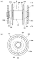
- the drum 32 is comprised from the drum main body 320 in which the suspension belt 33 is wound, and the drive part 330 for rotating the drum main body 320, as shown to FIG. 5 (A) (B).
- the drum main body 320 includes a cylindrical pulley portion 321, a cylindrical portion 322 coaxially provided on both sides in the axial direction of the pulley portion 321, and a disc portion 324 attached in a bowl shape around each cylindrical portion 322.
- the suspension belt 33 is configured to be wound at a position between the two disc portions 324.
- each disc portion 324 On the outer peripheral surface of each disc portion 324, a ring-shaped step portion 324d which can be fitted to a support hole 415s of the first bracket 41 and a support hole 424s of the second bracket 42 described later is formed.
- a through hole 325 is formed in the axial direction at the center of the drum main body 320, and the support shaft 333 of the drive unit 330 is passed through the through hole 325.
- drum side gears 335a and 335b smaller in diameter than the ring-shaped step portion 324d are fixed to both ends of the support shaft 333 protruding from the through hole 325 of the drum main body 320 by caulking, for example.
- the support shaft 333 of the drive unit 330 is passed through the through hole 325 of the drum main body 320, and then fixed to the drum main body 320 in a state of being rotationally locked by a bolt or the like. For this reason, the drum main body 320 and the drive part 330 come to rotate integrally. That is, the drum side gears 335a and 335b correspond to the rotating body side gear of the present invention.
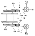
- the first motor unit 51 includes a first motor M1 and a worm gear 110.
- the first motor M1 and the worm gear 110 are accommodated in a motor housing 51h (see FIG. 2).
- the worm gear 110 is composed of a worm 111 and a worm wheel 113 provided coaxially to the rotational shaft (not shown) of the first motor M1.
- the worm wheel 113 is provided coaxially with a small diameter first gear 113x. ing.
- the first gear 113x meshes with the drum gear 335a provided at one end of the drum 32.
- the first bracket 41 and the second bracket 42 are members to which the drum 32 is rotatably supported and to which the first motor unit 51 and the second motor unit 52 for driving the drum 32 are attached.
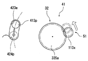
- the second bracket 42 is substantially formed by the left side plate portion 421, the right side plate portion 422, and the flat plate portion 423 passed between the side plate portions 421 and 422. It is formed in a portal shape. Then, the left side plate portion 421 and the right side plate portion 422 of the second bracket 42 are fixed to the carrier 22 of the wheelchair support portion 20 described above by, for example, a bolt or the like. As shown in FIG.
- a substantially egg-shaped opening 423 h (see dotted line) is formed in the central portion of the flat plate portion 423 of the second bracket 42, and a fixed gap is formed by the front side flat plate 424 around the opening 423 h. It is covered in parallel from the front side (lower side in FIG. 6) in the interposed state.
- a support hole 424s rotatably supporting the ring-shaped step portion 324d of the drum main body 320 is formed at the center position of the front flat plate 424 so as to overlap with the opening 432h of the flat plate portion 423.
- an arc-shaped elongated hole 423e is formed on the left side portion of the flat plate portion 423, and the arc center of the elongated hole 423e coincides with the center of the support hole 424s. Is configured.
- a stopper 424p is formed along the peripheral edge (lower peripheral edge in FIG. 3) of the long hole 423e of the flat plate portion 423.
- a plurality of (three) screw holes 423x are formed on the right side of the opening 423h of the flat plate portion 423 so as to surround the opening 423h, as shown in FIG.
- the second motor unit 52 is screwed from the back side.
- one screw hole 423y used to connect a first bracket 41 described later to the second bracket 42 is formed at the right end and two at the left end.
- the first bracket 41 is substantially formed by the left side plate 411, the right side plate 412, and the flat plate 413 delivered between the side plates 411 and 412, as shown in FIGS. It is formed in a portal shape. As shown in FIG. 6, flange portions 411 f and 412 f bent in the lateral direction are formed at the tips of the left side plate portion 411 and the right side plate portion 412, and bolt holes 411 b are formed in the flange portion 411 f of the left side plate portion 411. Two bolt holes 412 b are formed in the flange portion 412 f of the right side plate portion 412. Then, as shown in FIG.
- the first bracket 41 is connected to the second bracket 42 by screwing the bolts B passed through the respective bolt holes 411 b and 412 b into the screw holes 423 y of the second bracket 42.
- Ru in the flat plate portion 413 of the first bracket 41, as shown in FIG. 4, a substantially oval opening 413h is formed in the central portion, and the periphery of the opening 413h is a constant gap by the back side flat plate 415 (see FIG. 6). It is covered in parallel from the back side in the state through.
- a support hole 415 s rotatably supporting the ring-shaped step portion 324 d of the drum main body 320 is formed at the center position of the back side flat plate 415 so as to overlap with the opening 413 h of the flat plate portion 413.
- a pin 413p inserted into the long hole 423e at a position corresponding to the arc shaped long hole 423e of the second bracket 42 It is provided at a right angle to 415 and the like. Therefore, as shown in FIGS. 2 and 6, the ring-shaped step portions 324d on both axial sides of the drum 32 are fitted in the support holes 415s of the first bracket 41 and the support holes 424s of the second bracket 42.
- the pin 413 p of the first bracket 41 can be inserted into the long hole 423 e of the second bracket 42.
- the first bracket 41 and the second bracket 42 can be relatively rotated about the drum 32 by the length of the elongated hole 423 e. Furthermore, on the right side of the opening 413 h in the flat plate portion 413 of the first bracket 41, a plurality of (three) screw holes 413 x are formed so as to surround the opening 413 h. As shown in FIG. 2, the first motor unit 51 is screwed from the outside. That is, the pin 413p and the elongated hole 423e correspond to the guide mechanism of the present invention.
- the support hole 415s of the first bracket 41 is fitted to the ring-shaped step portion 324d of the other end (the first bracket 41 side) of the drum 32, and the pin 413p of the first bracket 41 is a second bracket 42 is inserted into the long hole 423 e.
- the first bracket 41 is slightly rotated right around the drum 32 with respect to the second bracket 42, and the teeth (tooth grooves) of the drum side gear 335a of the drum 32 and the first gear 113x of the first motor unit 51 And the gear teeth (tooth) of the gear, and the two gears 335a and 113x are engaged.
- the first motor M1 of the first motor unit 51 is driven to rotate the first gear 113x to the left in FIG. 7 and to rotate the first bracket 41 to the left about the drum 32 with respect to the second bracket 42. Then, the first motor M1 is stopped in a state where the pin 413p of the first bracket 41 is in contact with the stopper 424p of the long hole 423e of the second bracket 42. In this state, the bolt holes 411 b and 412 b of the first bracket 41 overlap the screw holes 423 y of the second bracket 42. Next, the first bracket 41 is connected to the second bracket 42 by inserting a bolt B through each of the bolt holes 411b and 412b and screwing the bolts B into the screw holes 423y.
- the assembly of the drum 32 to the first bracket 41 and the second bracket 42 is completed. That is, the first when the pin 413 p of the first bracket 41 abuts against the stopper 424 p of the long hole 423 e of the second bracket 42 and the bolt holes 411 b and 412 b of the first bracket 41 overlap the screw hole 423 y of the second bracket 42.
- the positions of the motor unit 51 and the second motor unit 52 correspond to the correct mounting positions in the present invention.
- the pin 413p for guiding the first motor unit 51 and the second motor unit 52 relatively rotatably around the drum 32 and An elongated hole 423 e (guide mechanism) is provided. Therefore, for example, with respect to the second motor unit 52 and the drum side gears 335a and 335b in a state where the second motor unit 52 is held at the correct mounting position and the second gear 123x and the drum side gear 335b are engaged.
- the first motor unit 51 can be gradually rotated (moved) around the drum 32, and the teeth (tooth grooves) of the first gear 113x and the tooth grooves (tooth) of the drum side gear 335a can be aligned. Then, after the meshing of the first gear 113x and the second gear 123x with the drum side gears 335a and 335b is completed, the first motor unit 51 can be properly attached using the pin 413p and the elongated hole 423e (guide mechanism). It can be moved around the drum 32. Thus, the meshing operation between the first gear 113x of the first motor unit 51 and the drum side gear 335a, and the second gear 123x of the second motor unit 52 and the drum side gear 335b becomes easy, and Assembly work efficiency is improved.
- the bracket is composed of the first bracket 41 and the second bracket 42 supporting one end and the other end of the drum 32, the mounting of the drum 32 on the bracket is facilitated. Furthermore, since the first motor unit 51 is attached to the first bracket 41 and the second motor unit 52 is attached to the second bracket 42, the meshing of the first gear 113x and the second gear 123x with the drum side gears 335a and 335b Work becomes easy, too.
- the drum side gears 335a and 335b are respectively provided on one end side and the other end side of the drum 32 in the axial direction, and the drum side gear 335a on one end side of the drum 32 in the axial direction meshes with the first gear 113x.
- the drum side gear 335b at the other axial end side of the drum 32 meshes with the second gear 123x. That is, since the rotational force is applied to both sides of the drum 32 in the axial direction, the drum 32 can be rotated in a well-balanced manner.
- the guide mechanism is composed of a pin 413p and an arc-shaped elongated hole 423e for guiding the pin 413p, and the suspension belt 33 wound around the drum 32 is supported by the pin 413p. Therefore, the structure of the guide mechanism is simplified, and the guide mechanism can be used as a guide for the suspension belt 33.
- the guide mechanism includes the pin 413p and the long hole 423e.
- the guide mechanism includes a ridge and an arc-shaped groove for guiding the ridge.
- the drum 32 is supported by the first bracket 41 and the second bracket 42.
- the drum is supported by one bracket, and the first motor unit 51 or the second motor is supported. It is also possible to support the unit so as to be rotatable around the drum with respect to the bracket by the guide mechanism.
- the winding device 30 of the wheelchair storage device 10 is illustrated in the present embodiment, the present invention can also be applied to a winding device such as a winch or a crane.
- the hoisting device according to the present embodiment is used in a wheelchair storage device which is stored on the roof of a passenger car after being folded while lifting a wheelchair.
- front and rear, right and left and upper and lower in the figure correspond to front and rear, left and right and upper and lower of a passenger car and a wheelchair.
- ⁇ Conventional structure> In the conventional hoisting device, as shown in FIGS. 18A and 18B, when lifting up the wheelchair K, the hook receiver of the wheelchair K is held by hand by holding the hook shaped hook 115 provided at the tip of the suspension belt 110. The belt 100 is to be hung.
- the hook 115 is manufactured to be as thin and lightweight as possible as shown in FIG. 18B so as to be easy to hold.
- the hooks 115 since it is necessary to hold the hook 115 by hand and hook it on the hook receiving belt 100 of the wheelchair K, it is difficult for a person with a finger to perform this work.
- the hooks 115 since the hooks 115 are made thin, the hooks 115 lowered onto the seat surface of the wheelchair K may fall on the seat surface, making it difficult for a handicapped person to grasp.
- the problem to be solved by the hoisting device according to the present embodiment is that even a person with a finger can easily hook the hook lowered on the seating surface of the wheelchair to the hook receiving belt provided on the seating surface of the wheelchair To be able to
- the vehicle wheelchair storage device 10 is a device for lifting the wheelchair K and storing it on the roof of the car C after the driver gets over from the wheelchair K to the driver's seat of the car C.
- the wheelchair storage device 10 for a vehicle includes a wheelchair support portion 20 configured to be vertically rotatable between an upright position and a horizontal position (not shown) shown in FIG. 9A, and a wheelchair support portion in the horizontal position.
- 20 a device body (not shown) for laterally sliding the housing 20 to the storage position on the roof.
- the wheelchair support unit 20 includes a carrier 22 connected to the device body in a vertically rotatable state, a protector 25 for restraining the wheelchair K folded in the lifting process at a predetermined position, and the protector 25 as the carrier 22.
- a carrier 22 connected to the device body in a vertically rotatable state
- a protector 25 for restraining the wheelchair K folded in the lifting process at a predetermined position
- the protector 25 as the carrier 22.
- it comprises a guide mechanism 23 connected so as to be slidable up and down, and a hoisting device 30 capable of lifting the wheelchair K and the protector 25 with respect to the carrier 22.
- the winding device 30 comprises a suspension belt 33, a hook 35 connected to the suspension belt 33, and a rotating device 30m capable of winding or unwinding the suspension belt 33.
- the drum 32 of the rotating device 30 m is fixed to the upper end of the carrier 22.
- the drum 32 is attached to the upper end of the carrier 22 by a first bracket 41 and a second bracket 42 (see FIG. 2).
- a first motor unit 51 for rotating the drum 32 is attached to the first bracket 41
- a second motor unit for rotating the drum 32 is attached to the second bracket 42. 52 is attached.
- FIG. 1 a first motor unit 51 for rotating the drum 32 is attached to the first bracket 41
- a second motor unit for rotating the drum 32 is attached to the second bracket 42. 52 is attached.
- the middle portion is passed through the suspension fulcrum 25c formed at the upper end of the protector 25, and the tip portion is a component of the suspension fulcrum 25c using the snap ring 33w. It is connected.
- the fulcrum 35c of the hook 35 is hooked on the middle of the suspension belt 33 passed through the suspension fulcrum 25c of the protector 25. That is, the hook 35 is supported by the suspension belt 33 so as to be movable along the middle of the suspension belt 33 below the suspension fulcrum 25 c of the protector 25.
- the wheelchair K abuts on the wheelchair restraint plate 25x (see FIG. 9A) of the protector 25 and is restrained at this position.
- the suspension belt 33 is continuously wound from this state, the wheelchair K is lifted together with the protector 25. That is, the wheelchair K and the protector 25 move up with respect to the carrier 22 by the action of the guide mechanism 23.
- the carrier 22 is rotated to the horizontal position, and the protector 25 and the wheelchair K are placed on the carrier 22.
- the device body slides the wheelchair support 20 (the protector 25 and the carrier 22) to the storage position on the roof, and the storage of the wheelchair K is completed.
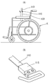
- the hook 35 of the hoisting device 30 is hooked on the hook receiving belt 141 of the wheelchair K in a state of being lowered onto the seat surface 143 of the wheelchair K as shown in FIG. 10 (A) (B). It is configured to stand on its own in the same posture as that of time.
- the hook 35 has a hook proximal end 351 having the fulcrum 35c, a belt hook 353 on which the hook receiving belt 141 of the wheelchair K is hooked, and a guide for guiding the hook receiving belt 141 to the belt hook 353.
- a unit 356 As shown in FIG.
- the hook proximal end 351 is formed in a substantially elliptical shape that is long in the width direction, and a laterally long belt hole 35 h is formed in the upper part of the hook proximal end 351.
- the suspension belt 33 of the winding device 30 is passed through the belt hole 35h, and is put on a horizontal axis fulcrum 35c formed on the upper side of the belt hole 35h.
- the belt hooking portion 353 is a strip-shaped portion whose width dimension is set smaller than the width dimension of the hook base end 351 and the side shape is as shown in FIG. 10B. As shown in, it is formed in a substantially arc shape.
- a laterally curved portion 35 w is provided between the proximal end portion of the belt hooking portion 353 and the lower end central portion of the hook proximal end portion 351.
- the curvature of the laterally curved portion 35w is set such that the fulcrum 35c of the hook proximal end portion 351 is disposed almost directly above the belt hooking portion 353.
- the substantially central lower surface 353 d of the belt hooking portion 353 and its vicinity come into contact with the seating surface 143 of the wheelchair K.
- the radius of curvature of the belt hook 353 having a substantially arc shape is set to a value smaller than the radius of a virtual arc E passing through the surface of the belt hook 353 about the fulcrum 35 c of the hook proximal end 351. . Therefore, even when the hook 35 pivots around the fulcrum 35 c in the rotational direction, the hook receiving belt 141 of the wheelchair K is not easily detached from the belt hooking portion 353 of the hook 35.
- the guide portion 356 has a width equal to that of the belt hook 353 and is formed in a flat strip shape. Further, a downward curved portion 35 d is provided between the proximal end of the guide portion 356 and the tip of the belt hooking portion 353. The lower curved portion 35 d is a portion that bends the guide portion 356 downward with a gentle curvature with respect to the belt hooking portion 353. The length dimension of the guide portion 356 is set such that the position of the center of gravity G of the hook 35 is on the front side of the fulcrum 35 c of the hook proximal end portion 351.
- the tip end side (guide portion 356 side) of the hook 35 becomes lowest.
- the tip lower side 356x first abuts on the seat surface 143 of the wheelchair K. Then, as the hooks 35 are continuously lowered, the central lower surface 353 d of the belt hooking portion 353 and the vicinity thereof come in contact with the seating surface 143 of the wheelchair K (see FIG. 10B).
- the tip lower side 356x of the guide portion 356 in the hook 35, the central lower surface 353d of the belt hooking portion 353 and the vicinity thereof correspond to the seat surface contact portion in the hook of the present invention. Therefore, the distance from the lower end 356x of the guide portion 356 to the central lower surface 353d of the belt hooking portion 353 and the vicinity thereof corresponds to the distance from the front end position to the rear end position in the seat surface contact portion. Further, the width dimension of the guide portion 356 and the belt hook portion 353 is equal to the distance from the left end to the right end of the seat surface contact portion.
- the hook 35 is set at such a value that the hook 35 can stand on the seating surface 143 stably and in a state where the hook 35 is lowered, that is, in a state where the tension of the suspension belt 33 is not applied to the hook 35. For this reason, as shown in FIG. 12, after the hook 35 is lowered onto the seating surface 143 of the wheelchair K, for example, the hook 35 is pushed along the seating surface 143 to bring the hook 35 onto the seating surface 143 of the wheelchair K. You will be able to move along.
- the hook 35 is configured by covering the periphery of the aggregate formed of a steel plate with a resin such as nylon, for example.
- a hook receiving belt 141 is disposed on the seating surface 143 of the wheelchair K so as to cross the seating surface 143, and both ends of the hook receiving belt 141 are on the frame 146 of the wheelchair K (see FIG. 11). It is connected. For this reason, as shown in FIG. 10B and FIG. 12, a gap S is formed between the central portion of the hook receiving belt 141 and the seating surface 143. Therefore, as shown in FIG. 12, after the hook 35 is lowered onto the seating surface 143 of the wheelchair K by the suspension belt 33, the hook 35 is pushed forward to advance the seating surface 143, whereby the guide portion of the hook 35 is moved.
- the tip end of 356 can be inserted into the gap S between the seat surface 143 and the hook receiving belt 141. Then, by further pushing the hook 35 forward from this state, the hook receiving belt 141 is relatively moved from the position of the guide portion 356 to the position of the belt hooking portion 353 as shown by a two-dot chain line in FIG. be able to. That is, since the posture when the hook 35 is lowered onto the seat surface 143 of the wheelchair K is the same as the posture when the hook 35 is hooked on the hook receiving belt 141 of the wheelchair K, the hook 35 It is possible to hook the hook 35 on the hook receiving belt 141 of the seating surface 143 simply by pushing it forward.
- the posture of the hook 35 is the same as the posture when hooked on the hook receiving belt 141 of the wheelchair K. Stand by yourself. For this reason, the hook 35 is lowered by lowering the hook 35 onto the seating surface 143 of the wheelchair K and moving the hook 35 along the seating surface 143 to the position of the hook receiving belt 141 while pushing the hook 35. It becomes possible to hang on the belt 141. That is, since it is not necessary to hold the hook 35 and hook it on the hook receiving belt 141, even a person with a finger can easily hook the hook 35 on the hook receiving belt 141.
- the guide portion 356 of the hook 35 when moving the hook 35 along the seating surface 143 of the wheelchair K, the guide portion 356 of the hook 35 always abuts on the seating surface 143 as shown in FIG. It is configured to be able to enter the gap S between the receiving belts 141. For this reason, the hook receiving belt 141 is reliably guided to the position of the belt hooking portion 353 by pushing the hook 35 and pushing the guide portion 356 of the hook 35 into the gap S between the seat surface 143 and the hook receiving belt 141. Can.
- the radius of curvature of the belt hooking portion 353 of the hook 35 is set to a value smaller than the radius of the virtual arc E passing through the surface of the belt hooking portion 353 with the fulcrum 35c of the hook 35 as a center. Therefore, even when the hook 35 pivots around the fulcrum 35 c in the rotational direction, the hook receiving belt 141 of the wheelchair K is not easily detached from the belt hooking portion 353 of the hook 35.
- the present invention is not limited to the above embodiment, and modifications can be made without departing from the scope of the present invention.
- the width dimension of the belt hooking portion 353 and the guide portion 356 is set smaller than the width dimension of the hook base end 351.
- the seat lower surface 356x of the guide portion 356 and the central lower surface 353d of the belt hook 353 have a seat surface for the wheelchair K. The example which abuts on 143 is shown.
- the entire lower side of the hook 35 from the tip lower side 356x of the hook 35 to the central lower surface 353d in a planar shape and abut the entire lower plane to the seating surface 143 of the wheelchair K. By doing this, the independent posture of the hook 35 on the seat surface 143 of the wheelchair K becomes stable.
- the example which comprises the hook 35 from the aggregate made from a steel plate, and the coating material made from nylon was shown, the material of the hook 35 can be changed suitably.
- the winding device according to the present embodiment is an improvement of the connection structure between the hooks 35 and the suspension belts 33, and the other configuration is the same as that of the winding device 30 according to the first embodiment. Therefore, the same members as those of the winding device 30 according to the second embodiment are denoted by the same reference numerals, and the description thereof is omitted.
- ⁇ Conventional connection structure> Conventionally, as shown in FIG. 13E, the horizontal belt-like fulcrum 35c of the hook 35 is directly passed through the cylindrical portion W formed at the tip end portion of the suspension belt 33. It was made to connect with the hook 35.
- the cylindrical portion W is formed by winding the area 33a near the tip of the suspension belt 33 around the horizontal axis fulcrum 35c of the hook 35 and sewing the belt tip 33t to the side of the area 33a near the tip.
- the hook 35 when the hook 35 is removed from the suspension belt 33, it is necessary to cut the thread of the sewn portion and remove the belt tip 33t from the side surface of the range 33a near the tip of the suspension belt 33.
- the retaining ring 60 is a substantially oval shaped annular member, and has a straight side 61 and a straight other side 62 opposite to the side 61 with respect to the center and a side thereof. It comprises a semicircular arc portion 63 connecting the one end side 61 and the other end side of the other side portion 62 respectively. As shown in FIG. 13C, the center position of the other side portion 62 of the retaining ring 60 is cut, and a gap 65 is formed in the cut portion.
- the width dimension of the gap 65 is set to a value slightly larger than the thickness dimension of the suspension belt 33. Therefore, it is possible to guide the suspension belt 33 to the retaining ring 60 from the outside to the inside by utilizing the gap 65.
- the length dimension of the snap ring 60 that is, the dimension from the outer peripheral surface of one arc portion 63 to the outer peripheral surface of the other arc portion 63 is the width dimension of the hook base end portion 351 of the hook 35 It is set smaller than the length dimension in the direction (see FIG. 14 etc.).
- FIG. 13 (D) An example of the connection structure of the hook 35 and the suspension belt 33 using the retaining ring 60 is shown in FIG. 13 (D).
- the suspension belt 33 is passed through the belt holes 35 h of the hooks 35, and then the cylindrical portion W of the suspension belt 33 is used for the one side portion 61 of the retaining ring 60 using the gap 65 of the retaining ring 60. Try to hang on.
- the middle portion 33e of the suspension belt 33 located between the fulcrum 35c of the hook 35 and the drum 32 (not shown in FIG. 13) is guided from the gap 65 of the snap ring 60 to the inside of the snap ring 60 Pass the wheel 60. Thereby, as shown in FIG.
- the hook 35 and the suspension belt 33 are connected via the retaining ring 60. According to this connection structure, it is possible to easily remove the hook 35 from the suspension belt 33 in the reverse procedure to the above procedure. Therefore, the hook 35 and the hanging belt 33 can be replaced individually.
- the retaining ring 60 is inclined. For this reason, when the hook 35 is wound up to the upper limit position, a part of the retaining ring 60 abuts against the hook stopper 67 shown in FIGS. 17A and 17B first, and the hook 35 sways unstably. . For this reason, the member which prevents interference with the hook 35 and peripheral parts is needed.
- the hook 60 and the suspension belt 33 are connected as shown in FIGS. 13A and 13B. There is.
- connection structure Using Retaining Ring 60 According to This Embodiment>
- the tubular portion W of the suspension belt 33 is hooked on one side 61 of the retaining ring 60 using the gap 65 of the retaining ring 60, and further, the tip portion of the suspending belt 33 Pass through the inside of the retaining ring 60.
- the vicinity (tip portion) of the cylindrical portion W of the suspension belt 33 is folded back to a fixed length and doubled, and the folded portions 33 x and 33 y (overlapped portions) are hooked Pass through 35 belt holes 35h.
- an elastic cylindrical cover member 68 is placed from one side 61 of the retaining ring 60 to the arcs 63 on both sides. It is also possible to pass the folded portions 33x and 33y of the suspension belt 33 through the belt holes 35h of the hooks 35 after the cover ring 68 is covered with the cover member 68.
- the folded end 33z (double portion) of the folded portion 33 of the suspension belt 33 uses the gap 65 of the retaining ring 60 to make the retaining ring 60 is applied to the other side 62. In this state, the connection between the hook 35 and the suspension belt 33 is completed.
- the cover member 68 is omitted in FIGS. 13 (A) and 13 (B) and the like.
- the cylindrical portion W at the tip end of the suspension belt 33 is fixed to the one side portion 61 of the retaining ring 60, and the middle portion is hung from the outside on the other side portion 62 of the retaining ring 60.
- a part (folded portion 33x) of the suspension belt 33 passed from one side 61 of the retaining ring 60 to the other side 61, the other side 62 of the retaining ring 60 and the drum A part of the suspension belt located between 32 and 32 (folded portion 33 y) is passed in a state of being overlapped, and is hung on the horizontal axis fulcrum 35 c of the hook 35.
- the suspension belt 33 can be removed from the hook 35 in the reverse procedure to the above procedure from this state.
- the suspension belt 33 from the hook 35 is compared with a configuration in which the hook 35 and the suspension belt 33 are directly connected. Can be easily removed. Therefore, single item exchange of the hook 35 and the suspension belt 33 is possible.
- the overlapped portions (folded portions 33x and 33y) of the suspension belt 33 are hooked on the fulcrum 35c of the hook 35. Therefore, when tension is temporarily applied to the suspension belt 33 and the suspension belt 33 (folded portions 33x and 33y) between the hook 35 and the retaining ring 60 is tightened, the folded portion 33x of the suspension belt 33, even if the tension is released. It becomes difficult to loosen 33y. That is, the hook 35 and the retaining ring 60 are in a state of being tied by the suspension belt 33. Therefore, the retaining ring 60 does not hit the hook 60 every time the suspension belt 33 is wound up, so that generation of abnormal noise can be suppressed and damage to the hook 60 or the like with time can be prevented.
- the present invention is not limited to the above embodiment, and modifications can be made without departing from the scope of the present invention.
- the connection structure of the hook 35 and the suspension belt 33 according to the present embodiment an example is shown in which the snap ring 60 in which a gap 65 is formed by cutting one place in the circumferential direction is used.
- the suspension belt 33 is passed through the retaining ring 60 and the belt hole 35 h of the hook 35 in order from the front end, the gap 65 of the retaining ring 60 can be omitted.
- the example which covers the stop ring 60 with the cover member 68 was shown in this embodiment, if the stop ring 60 and the hook 35 are resin-coated, for example, it will also be possible to abbreviate the cover member 68.
- the hook is formed with a belt hole through which the suspension belt passes, and a fulcrum on which the suspension belt is hung is provided above the belt hole,
- the suspension belt is mounted on a drum capable of winding up or unwinding the suspension belt, and the tip portion is fixed to one side of a ring-shaped retaining ring, and the middle portion is opposite to the one side of the retaining ring with respect to the center It is a configuration that can be hung from the outside on the other side of the retaining ring located at In the belt hole of the hook, a part of the suspension belt passed from one side of the retaining ring to the other side of the retaining ring, and one of the suspending belts located between the other side of the retaining ring and the drum
- a winding device characterized in
- [Claim 2] A hoisting device described in claim 1; A winding apparatus characterized in that the retaining ring is cut at one place in the circumferential direction to form a gap, and the suspension belt can be guided from the outside to the inside of the retaining ring from the gap.
- [Claim 3] A hoisting device described in either of Claim 1 or Claim 2; A winding device characterized in that a cover member that covers the retaining ring is provided.
Landscapes
- Engineering & Computer Science (AREA)
- Mechanical Engineering (AREA)
- Health & Medical Sciences (AREA)
- Public Health (AREA)
- General Health & Medical Sciences (AREA)
- Animal Behavior & Ethology (AREA)
- Life Sciences & Earth Sciences (AREA)
- Veterinary Medicine (AREA)
- Fittings On The Vehicle Exterior For Carrying Loads, And Devices For Holding Or Mounting Articles (AREA)
- Gear Transmission (AREA)
- Connection Of Motors, Electrical Generators, Mechanical Devices, And The Like (AREA)
- Invalid Beds And Related Equipment (AREA)
- General Details Of Gearings (AREA)
Priority Applications (4)
| Application Number | Priority Date | Filing Date | Title |
|---|---|---|---|
| EP10804190.6A EP2460690B1 (en) | 2009-07-27 | 2010-06-07 | Rotary device and winch provided with rotary device |
| US13/386,007 US8777185B2 (en) | 2009-07-27 | 2010-06-07 | Rotary device and winch provided with rotary device |
| CN201080033663.3A CN102481877B (zh) | 2009-07-27 | 2010-06-07 | 转动装置和具有转动装置的卷收装置 |
| IN675DEN2012 IN2012DN00675A (https=) | 2009-07-27 | 2010-06-07 |
Applications Claiming Priority (4)
| Application Number | Priority Date | Filing Date | Title |
|---|---|---|---|
| JP2009174124A JP5201100B2 (ja) | 2008-11-05 | 2009-07-27 | 車椅子吊り装置 |
| JP2009-174124 | 2009-07-27 | ||
| JP2009-176672 | 2009-07-29 | ||
| JP2009176672A JP5282696B2 (ja) | 2009-07-29 | 2009-07-29 | 回転装置 |
Publications (1)
| Publication Number | Publication Date |
|---|---|
| WO2011013443A1 true WO2011013443A1 (ja) | 2011-02-03 |
Family
ID=43529107
Family Applications (1)
| Application Number | Title | Priority Date | Filing Date |
|---|---|---|---|
| PCT/JP2010/059617 Ceased WO2011013443A1 (ja) | 2009-07-27 | 2010-06-07 | 回転装置及びこの回転装置を備える巻き上げ装置 |
Country Status (6)
| Country | Link |
|---|---|
| US (1) | US8777185B2 (https=) |
| EP (1) | EP2460690B1 (https=) |
| JP (1) | JP5282696B2 (https=) |
| CN (1) | CN102481877B (https=) |
| IN (1) | IN2012DN00675A (https=) |
| WO (1) | WO2011013443A1 (https=) |
Families Citing this family (5)
| Publication number | Priority date | Publication date | Assignee | Title |
|---|---|---|---|---|
| CN104864073A (zh) * | 2015-05-08 | 2015-08-26 | 博艳萍 | 一种双向安装式齿轮驱动机构 |
| CN105078666B (zh) * | 2015-07-31 | 2017-07-28 | 浙江双友物流器械股份有限公司 | 一种轮椅的固定装置 |
| JP6670705B2 (ja) * | 2016-08-02 | 2020-03-25 | 株式会社ミツバ | 反力発生装置 |
| DE202017100264U1 (de) * | 2017-01-19 | 2017-03-22 | Reschwitzer Saugbagger Produktions Gmbh | Vorrichtung zur Aufnahme und zum Transport von Bauteilen, insbesondere Schläuchen oder Rohren, Materialsammelbehälter für ein Fahrzeug sowie Saugbagger mit einer solchen Vorrichtung |
| US11999311B2 (en) | 2019-05-22 | 2024-06-04 | Valeda Company, Llc | Energy management system |
Citations (9)
| Publication number | Priority date | Publication date | Assignee | Title |
|---|---|---|---|---|
| JPS5958205A (ja) * | 1982-09-28 | 1984-04-03 | Uchida Yuatsu Kiki Kogyo Kk | 複数個の油圧モ−タの制御回路装置 |
| JPS60114187U (ja) * | 1984-01-11 | 1985-08-02 | 株式会社神戸製鋼所 | ウインチ |
| JP3016800U (ja) * | 1995-04-11 | 1995-10-09 | 青木精密工業株式会社 | 巻取ドラムの駆動装置 |
| JPH1077192A (ja) * | 1996-05-31 | 1998-03-24 | Slingmax Inc | フラット・スリング継手構造 |
| JPH11228069A (ja) * | 1998-02-12 | 1999-08-24 | Araco Corp | 固縛ベルトにおける吊り金具の脱落防止構造 |
| JP2000053381A (ja) | 1998-08-04 | 2000-02-22 | Ryozo Matsumoto | ウインチ |
| JP2002003146A (ja) * | 2000-06-16 | 2002-01-09 | Elephant Chain Block Co Ltd | ベルト式巻上機 |
| JP2006501100A (ja) * | 2002-10-04 | 2006-01-12 | アンダーソン,シャーロット セラ | 自動車用のボックス機構 |
| JP2009078679A (ja) * | 2007-09-26 | 2009-04-16 | Toyota Auto Body Co Ltd | 車両用車椅子格納装置 |
Family Cites Families (11)
| Publication number | Priority date | Publication date | Assignee | Title |
|---|---|---|---|---|
| US2967494A (en) * | 1958-04-14 | 1961-01-10 | Morton M Rosenfeld | Public bombshelter |
| DE3223203C1 (de) * | 1982-06-22 | 1983-12-29 | Thyssen AG vorm. August Thyssen-Hütte, 4100 Duisburg | Verfahren und Anlage zur Herstellung bindemittelloser Heissbriketts |
| JPS60114187A (ja) | 1983-11-25 | 1985-06-20 | Agency Of Ind Science & Technol | 新規微生物 |
| JPS61175000A (ja) * | 1985-01-29 | 1986-08-06 | Agency Of Ind Science & Technol | メタン発酵法 |
| DE59510119D1 (de) * | 1995-11-06 | 2002-04-25 | Rollgliss Ag Zuerich | Auf-/abseilgerät |
| US6612265B1 (en) * | 2002-09-13 | 2003-09-02 | John P. Birdsong | Safety harness for transporting and training large animals |
| SE0202969L (sv) * | 2002-10-09 | 2003-11-04 | Thule Sweden Ab | Förankringsorgan |
| US7195433B2 (en) * | 2004-11-19 | 2007-03-27 | Cnh America Llc | Retractable tie down and method of using |
| JP4719184B2 (ja) * | 2007-06-01 | 2011-07-06 | 株式会社サイアン | 大気圧プラズマ発生装置およびそれを用いるワーク処理装置 |
| CN101396318A (zh) * | 2007-09-29 | 2009-04-01 | 安可拉日本株式会社 | 车椅固定装置及车椅 |
| GB0900944D0 (en) * | 2009-01-21 | 2009-03-04 | Cilliers Kobus J H | Portable winch assembly |
-
2009
- 2009-07-29 JP JP2009176672A patent/JP5282696B2/ja active Active
-
2010
- 2010-06-07 WO PCT/JP2010/059617 patent/WO2011013443A1/ja not_active Ceased
- 2010-06-07 EP EP10804190.6A patent/EP2460690B1/en not_active Not-in-force
- 2010-06-07 IN IN675DEN2012 patent/IN2012DN00675A/en unknown
- 2010-06-07 CN CN201080033663.3A patent/CN102481877B/zh not_active Expired - Fee Related
- 2010-06-07 US US13/386,007 patent/US8777185B2/en active Active
Patent Citations (9)
| Publication number | Priority date | Publication date | Assignee | Title |
|---|---|---|---|---|
| JPS5958205A (ja) * | 1982-09-28 | 1984-04-03 | Uchida Yuatsu Kiki Kogyo Kk | 複数個の油圧モ−タの制御回路装置 |
| JPS60114187U (ja) * | 1984-01-11 | 1985-08-02 | 株式会社神戸製鋼所 | ウインチ |
| JP3016800U (ja) * | 1995-04-11 | 1995-10-09 | 青木精密工業株式会社 | 巻取ドラムの駆動装置 |
| JPH1077192A (ja) * | 1996-05-31 | 1998-03-24 | Slingmax Inc | フラット・スリング継手構造 |
| JPH11228069A (ja) * | 1998-02-12 | 1999-08-24 | Araco Corp | 固縛ベルトにおける吊り金具の脱落防止構造 |
| JP2000053381A (ja) | 1998-08-04 | 2000-02-22 | Ryozo Matsumoto | ウインチ |
| JP2002003146A (ja) * | 2000-06-16 | 2002-01-09 | Elephant Chain Block Co Ltd | ベルト式巻上機 |
| JP2006501100A (ja) * | 2002-10-04 | 2006-01-12 | アンダーソン,シャーロット セラ | 自動車用のボックス機構 |
| JP2009078679A (ja) * | 2007-09-26 | 2009-04-16 | Toyota Auto Body Co Ltd | 車両用車椅子格納装置 |
Non-Patent Citations (1)
| Title |
|---|
| See also references of EP2460690A4 |
Also Published As
| Publication number | Publication date |
|---|---|
| EP2460690B1 (en) | 2014-06-04 |
| JP5282696B2 (ja) | 2013-09-04 |
| CN102481877A (zh) | 2012-05-30 |
| US8777185B2 (en) | 2014-07-15 |
| CN102481877B (zh) | 2015-04-01 |
| EP2460690A4 (en) | 2013-08-21 |
| JP2011033043A (ja) | 2011-02-17 |
| EP2460690A1 (en) | 2012-06-06 |
| IN2012DN00675A (https=) | 2015-08-21 |
| US20120273739A1 (en) | 2012-11-01 |
Similar Documents
| Publication | Publication Date | Title |
|---|---|---|
| WO2011013443A1 (ja) | 回転装置及びこの回転装置を備える巻き上げ装置 | |
| TWI441593B (zh) | 揚網機 | |
| JP4885073B2 (ja) | 風車回転翼の吊下げ装置、風車回転翼の取付け方法、および風力発電装置の建設方法 | |
| US20120121366A1 (en) | suspending member breakage preventing mechanism in a spare wheel holding apparatus | |
| KR20130107549A (ko) | 와이어 로프 릴 스탠드 | |
| BRPI0720816A2 (pt) | "dispositivo de retração de cinto de segurança" | |
| JP2004250155A (ja) | ロープウインチ | |
| JP2007297779A (ja) | ロールブラインド | |
| JP2005338085A5 (https=) | ||
| JP5540875B2 (ja) | ホイールクレーンのフック部保持具及びフック装置 | |
| JP4009979B2 (ja) | トラッククレーン投光機 | |
| JP4116632B2 (ja) | 建設機械用サイドミラー支持装置 | |
| JP7779158B2 (ja) | ロープ交換装置 | |
| JP2008247583A (ja) | クレーン用ウインチ装置 | |
| JP2010137976A (ja) | 巻上ウインチ装置およびクレーン | |
| JP3571374B2 (ja) | トラック荷箱のシート掛け装置 | |
| JP2001294389A (ja) | 重量物の吊上げ装置 | |
| KR100920588B1 (ko) | 씨-훅크의 코일 내경부 조정장치 | |
| JP2020164263A (ja) | クレーン | |
| JPH0213278Y2 (https=) | ||
| JP2000238584A (ja) | サイクルキャリア | |
| JPH0419925Y2 (https=) | ||
| KR200223283Y1 (ko) | 자동차 정비용 엔진홀더 | |
| JP2010047416A (ja) | 車載用クレーン装置 | |
| JPH04119285U (ja) | スペアタイヤハンガ構造 |
Legal Events
| Date | Code | Title | Description |
|---|---|---|---|
| WWE | Wipo information: entry into national phase |
Ref document number: 201080033663.3 Country of ref document: CN |
|
| 121 | Ep: the epo has been informed by wipo that ep was designated in this application |
Ref document number: 10804190 Country of ref document: EP Kind code of ref document: A1 |
|
| WWE | Wipo information: entry into national phase |
Ref document number: 2010804190 Country of ref document: EP |
|
| WWE | Wipo information: entry into national phase |
Ref document number: 13386007 Country of ref document: US |
|
| WWE | Wipo information: entry into national phase |
Ref document number: 675/DELNP/2012 Country of ref document: IN |
|
| NENP | Non-entry into the national phase |
Ref country code: DE |
|
| WWE | Wipo information: entry into national phase |
Ref document number: 1201000273 Country of ref document: TH |