WO2011007601A1 - 端子挿入装置 - Google Patents
端子挿入装置 Download PDFInfo
- Publication number
- WO2011007601A1 WO2011007601A1 PCT/JP2010/055050 JP2010055050W WO2011007601A1 WO 2011007601 A1 WO2011007601 A1 WO 2011007601A1 JP 2010055050 W JP2010055050 W JP 2010055050W WO 2011007601 A1 WO2011007601 A1 WO 2011007601A1
- Authority
- WO
- WIPO (PCT)
- Prior art keywords
- terminal
- cavity
- gripping
- housing
- guide
- Prior art date
- Legal status (The legal status is an assumption and is not a legal conclusion. Google has not performed a legal analysis and makes no representation as to the accuracy of the status listed.)
- Ceased
Links
Images








Classifications
-
- H—ELECTRICITY
- H01—ELECTRIC ELEMENTS
- H01R—ELECTRICALLY-CONDUCTIVE CONNECTIONS; STRUCTURAL ASSOCIATIONS OF A PLURALITY OF MUTUALLY-INSULATED ELECTRICAL CONNECTING ELEMENTS; COUPLING DEVICES; CURRENT COLLECTORS
- H01R43/00—Apparatus or processes specially adapted for manufacturing, assembling, maintaining, or repairing of line connectors or current collectors or for joining electric conductors
- H01R43/20—Apparatus or processes specially adapted for manufacturing, assembling, maintaining, or repairing of line connectors or current collectors or for joining electric conductors for assembling or disassembling contact members with insulating base, case or sleeve
-
- H—ELECTRICITY
- H01—ELECTRIC ELEMENTS
- H01R—ELECTRICALLY-CONDUCTIVE CONNECTIONS; STRUCTURAL ASSOCIATIONS OF A PLURALITY OF MUTUALLY-INSULATED ELECTRICAL CONNECTING ELEMENTS; COUPLING DEVICES; CURRENT COLLECTORS
- H01R4/00—Electrically-conductive connections between two or more conductive members in direct contact, i.e. touching one another; Means for effecting or maintaining such contact; Electrically-conductive connections having two or more spaced connecting locations for conductors and using contact members penetrating insulation
- H01R4/10—Electrically-conductive connections between two or more conductive members in direct contact, i.e. touching one another; Means for effecting or maintaining such contact; Electrically-conductive connections having two or more spaced connecting locations for conductors and using contact members penetrating insulation effected solely by twisting, wrapping, bending, crimping, or other permanent deformation
- H01R4/18—Electrically-conductive connections between two or more conductive members in direct contact, i.e. touching one another; Means for effecting or maintaining such contact; Electrically-conductive connections having two or more spaced connecting locations for conductors and using contact members penetrating insulation effected solely by twisting, wrapping, bending, crimping, or other permanent deformation by crimping
- H01R4/183—Electrically-conductive connections between two or more conductive members in direct contact, i.e. touching one another; Means for effecting or maintaining such contact; Electrically-conductive connections having two or more spaced connecting locations for conductors and using contact members penetrating insulation effected solely by twisting, wrapping, bending, crimping, or other permanent deformation by crimping for cylindrical elongated bodies, e.g. cables having circular cross-section
- H01R4/184—Electrically-conductive connections between two or more conductive members in direct contact, i.e. touching one another; Means for effecting or maintaining such contact; Electrically-conductive connections having two or more spaced connecting locations for conductors and using contact members penetrating insulation effected solely by twisting, wrapping, bending, crimping, or other permanent deformation by crimping for cylindrical elongated bodies, e.g. cables having circular cross-section comprising a U-shaped wire-receiving portion
- H01R4/185—Electrically-conductive connections between two or more conductive members in direct contact, i.e. touching one another; Means for effecting or maintaining such contact; Electrically-conductive connections having two or more spaced connecting locations for conductors and using contact members penetrating insulation effected solely by twisting, wrapping, bending, crimping, or other permanent deformation by crimping for cylindrical elongated bodies, e.g. cables having circular cross-section comprising a U-shaped wire-receiving portion combined with a U-shaped insulation-receiving portion
Definitions
- This invention relates to a technique for inserting a terminal connected to an end of an electric wire into a cavity of a terminal insertion housing.
- Patent Document 1 discloses a technique for inserting a terminal into a cavity.
- Patent Document 1 after inserting a terminal with a wire into the terminal accommodating chamber of the connector housing, the wire holding portion is retracted, a pulling force is applied to the terminal with a wire, and the pulling force is detected by a sensor. A technique for confirming the quality of the insertion state is disclosed.
- an object of the present invention is to enable a pulling force test to be performed more accurately.
- a terminal insertion device is a terminal insertion device for inserting a terminal of an electric wire with a terminal into a cavity formed in a terminal insertion housing, and a housing holding portion that holds the terminal insertion housing;
- a gripping part capable of gripping and releasing the end of the terminal-attached electric wire, an insertion advance / retreat driving part capable of driving the gripping part forward and backward with respect to the cavity, and the terminal-attached electric wire gripped by the gripping part.
- the gripping portion is moved forward toward the cavity so that a terminal is inserted into the cavity, and the terminal of the terminal-attached electric wire gripped by the gripping portion is required to be inserted into the cavity.
- An insertion operation control unit that moves the gripping part backward from the cavity with an upper limit thrust according to the pulling force, and when the gripping part is moved backward from the cavity. Based on the duration of the operation by the upper force limit in accordance with the pulling force that is the need, and a determination unit for determining acceptance or rejection of the withdrawal test terminals.
- the terminal insertion device is the terminal insertion device according to the first aspect, wherein the determination unit has a duration of operation by an upper limit thrust corresponding to the required pulling force in advance. It is determined whether or not a set determination time has elapsed, and when it is determined that the duration has passed the determination time, it is determined that the terminal pull-out test has passed.
- a terminal insertion device is the terminal insertion device according to the first or second aspect, wherein the housing holding portion is in a direction substantially orthogonal to the insertion direction of the electric wire with terminal with respect to the cavity.
- a housing movement drive mechanism for moving the housing.
- a terminal insertion device is the terminal insertion device according to any one of the first to third aspects, wherein the insertion advancing / retreating drive unit can be driven back and forth while supporting the gripping portion. And an insertion drive part side movement drive mechanism part that moves the insertion drive part together with the grip part in a direction substantially perpendicular to the insertion direction of the terminal-attached electric wire with respect to the cavity. .
- the influence of the external force is removed to some extent because it determines pass / fail of the terminal pull-out test based on the duration of the operation with the upper limit thrust according to the required pull-out force.
- the pulling force test can be performed more accurately.
- the terminal insertion device when it is determined that the continuation time has passed the determination time, it can be determined that the terminal pull-out test has passed.
- the housing by moving the housing, it is possible to perform the operation of inserting the terminal of the electric wire with terminal into each of the plurality of cavities formed in the terminal insertion housing.
- the insertion advance / retreat drive unit only needs to move the relatively lightweight gripping part back and forth, so that the pulling force actually acting on the terminal can be accurately reflected by the upper limit thrust of the insertion advance / retreat drive unit. And pull-out force test can be performed more accurately.
- the insertion drive unit by moving the insertion drive unit together with the gripping unit, it is possible to perform the operation of inserting the terminal of the electric wire with terminal into each of the plurality of cavities formed in the terminal insertion housing.
- the insertion advance / retreat drive unit only needs to move the relatively lightweight gripping part back and forth, so that the pulling force actually acting on the terminal can be accurately reflected by the upper limit thrust of the insertion advance / retreat drive unit. And pull-out force test can be performed more accurately.
- FIG. 1 is a perspective view showing a terminal insertion housing 10 and a terminal-attached electric wire 20.
- the terminal insertion housing 10 is formed in a substantially rectangular parallelepiped shape with an insulating material such as resin.
- the terminal insertion housing 10 is formed with at least one cavity 12, 14.
- a plurality of cavities 12 are formed so as to be arranged in a predetermined arrangement on one side region of one main surface of the terminal insertion housing 10, and a plurality of cavities are arranged in a predetermined arrangement on the other side region of the one main surface. 14 is formed.
- a peripheral wall portion 11 surrounding the plurality of cavities 12 and 14 is formed on one main surface of the terminal insertion housing 10.
- the cavities 12 and 14 are opened on one main surface side of the terminal insertion housing 10.
- the cavities 12 and 14 are formed in different openings and hole shapes.
- the terminal-attached electric wire 20 is configured such that the terminal 26 is connected to the end of the electric wire 22.
- the terminal 26 is formed to have a diameter, width and height corresponding to the cavities 12 and 14 to be inserted.
- the cavity 12 is smaller than the cavity 14, and therefore the terminal 26 inserted into the cavity 12 is smaller than the terminal inserted into the cavity 14.
- the electric wire 22 is a general coated electric wire in which a resin or the like is coated around a core wire such as a single wire or a twisted strand.
- the connection between the terminal 26 and the electric wire 22 is made by crimping connection, soldering connection, welding connection, a combination thereof, or the like.
- the terminal 26 and the electric wire 22 are crimped and connected.
- the terminal 26 When a terminal 26 having a corresponding size is inserted into each cavity 12 from the opening side, the terminal 26 is inserted and held in a state where the terminal 26 is positioned at a predetermined position in the cavity 12. In this state, the cylindrical portion on the distal end side of the terminal 26 or the lance portion formed in the cylindrical portion or the like is locked in the concave portion formed in the cavity 12, so that the terminal 26 is The cavity 12 is held in a retaining shape.
- a mating connector having a mating terminal can be connected to the connector from the side opposite to the one main surface. . That is, the terminal insertion housing 10 is used as a kind of connector.
- the terminal 26 and the like are inserted into the cavities 12 and 14, and the terminal 26 and the like are pulled out to test whether the terminal 26 and the like are inserted into the cavity 12 in a normal state. It is a device that determines whether or not.
- the overall configuration of the terminal insertion device particularly the operation for inserting the terminal 26 and the like into the cavities 12 and 14 will be mainly described, and then the configuration for performing the pull-out test will be described.
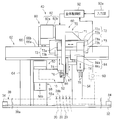
- 2 is a front view showing the terminal insertion device 40
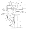
- FIG. 3 is a side view showing the terminal insertion device 40
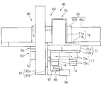
- FIG. 4 is a plan view showing the terminal insertion device 40
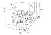
- FIG. FIG. 6 is a perspective view showing the main parts of the terminal insertion guide portion 76 and the terminal insertion drive mechanism portion 80
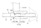
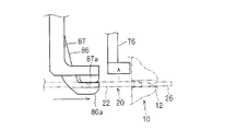
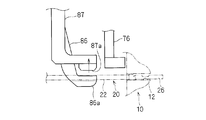
- FIG. 6 is an explanatory view showing the terminal 26 positioned by the terminal insertion guide portion 76.
- the terminal insertion device 40 includes a housing support mechanism 50, a terminal insertion guide mechanism 60, and an overall controller 92.
- the housing support mechanism portion 50 has a housing holding portion 52 that holds the terminal insertion housing 10 in a fixed posture, and is configured to move the housing holding portion 52 up and down.
- the terminal insertion guide mechanism section 60 serves as a terminal guide mechanism section 70 that guides the terminal 26 toward the cavities 12 and 14 and an insertion advance / retreat drive section that inserts and drives the terminal 26 into the cavities 12 and 14.
- a terminal insertion drive mechanism 80 and a common drive mechanism 62 that moves the terminal guide mechanism 70 and the terminal insertion drive mechanism 80 along the horizontal direction (left-right direction in FIG. 2) are provided.
- the terminal insertion housing 10 is moved up and down by the housing support mechanism 50, and the terminal guide mechanism 70 and the terminal insertion drive mechanism 80 are moved along the horizontal direction by the common drive mechanism 62.
- the part 70 and the terminal insertion drive mechanism 80 can be arranged to face each other in front of any one of the cavities 12 and 14.
- the terminal-attached electric wire 20 is set in the terminal guide mechanism portion 70 and the terminal insertion drive mechanism portion 80, so that the tip portions of the terminals 26 and the like are inserted into the cavities 12 and 14. Yes (see FIG. 6).
- the terminal 26 and the like can be inserted into the cavities 12 and 14 by driving the terminal insertion drive mechanism 80.
- the pulling test can be performed by applying a force in the pulling direction from the cavities 12 and 14 to the terminal 26 and the like by driving the terminal insertion driving mechanism 80 thereafter.
- the housing support mechanism portion 50 includes a housing holding portion 52 and a housing lifting / lowering drive mechanism portion 56.
- the housing elevating drive mechanism 56 is a linear motor, a linear drive mechanism having a screw shaft, a motor that rotationally drives the screw shaft, and a nut portion screwed to the screw shaft, or a linear actuator such as an air cylinder or a hydraulic cylinder.
- the housing elevating / lowering drive main body portion 56a is configured in a substantially vertical posture, and the housing elevating / lowering movable portion 56b is supported by the housing elevating / lowering drive main body portion 56a so as to be movable up and down.
- the housing elevating drive main body 56 a is erected and fixed on the base plate 32.
- the housing holding part 52 is configured to hold the terminal insertion housing 10 in a fixed posture, and is fixedly attached to the housing up-and-down moving part 56b.
- the housing holding portion 52 is configured to be able to hold the terminal insertion housing 10 in a posture (a posture facing the left side in FIG. 3) in which one main surface of the terminal insertion housing 10 is disposed in a substantially vertical posture.
- the structure which has a recessed part which can fit the outer peripheral part of the terminal insertion housing 10, or the structure which can pinch the terminal insertion housing 10 from both sides or the up-and-down side etc. can be used.
- the housing lifting / lowering drive mechanism 56 is configured so that the housing holding portion 52 is driven to move up and down along a substantially vertical direction substantially perpendicular to the insertion direction of the terminal 26 with respect to the cavities 12 and 14.
- the common drive mechanism 62 includes a support column 64 and a common horizontal drive mechanism 66.
- the support column 64 is configured to support the common horizontal drive mechanism 66 in a substantially horizontal posture.
- the column portions 64 are provided on the base plate 32 so as to be opposed to each other with an interval so as to sandwich the housing elevating drive mechanism portion 56.
- the height of the support column 64 is set so as to exceed the housing lifting drive mechanism 56.
- the common horizontal drive mechanism portion 66 is configured by a linear actuator as described above, and has a common horizontal drive main body portion 66a and a common horizontal movable portion 66b.
- the common horizontal drive main body 66a is attached and fixed to the upper ends of the pair of support columns 64 so as to be spanned between the upper ends of the pair of support columns 64.
- the common horizontal drive mechanism 66 is disposed in a substantially horizontal position above the housing lift drive mechanism 56, and the common horizontal movable part 66 b is substantially above the housing lift drive mechanism 56. It is movable along the horizontal direction.
- the terminal guide mechanism 70 and the terminal insertion drive mechanism 80 are moved along a substantially horizontal direction substantially orthogonal to the insertion direction of the terminal 26 with respect to the cavities 12 and 14. It is configured to be moved and driven together with a pair of gripping portions 86 and 87 and a terminal insertion guide portion 76 which will be described later.
- the terminal guide mechanism unit 70 guides the terminal-attached electric wire 20 so that the tip of the terminal 26 and the like is temporarily inserted into the cavities 12 and 14 before the terminal 26 is fully inserted into the cavities 12 and 14. Have a role to play.
- the terminal guide mechanism unit 70 includes a guide advance / retreat drive mechanism unit 71, a guide horizontal drive mechanism unit 72, a pair of guide lifting / lowering drive mechanism units 73, and a pair of guide head units 74. Yes.
- the guide advance / retreat drive mechanism 71 is configured by a linear actuator as described above, and includes a guide advance / retreat drive main body 71a and a guide advance / retreat movable part 71b.
- the guide advance / retreat drive main body 71a is attached and fixed on one side (the right side in FIGS. 2 and 4) of the common horizontal movable portion 66b.
- the guide advance / retreat movable part 71b can be driven to advance / retreat along the extending direction of the cavities 12, 14 on one end side (left end side in FIG. 3) of the guide advance / retreat drive main part 71a by the guide advance / retreat drive main part 71a. It is configured.
- the pair of guide heads 74 are driven to advance and retract between a position close to the front of the opening of the predetermined cavities 12 and 14 and a position separated from the front of the opening. It is configured.
- the guide advance / retreat drive mechanism 71 is configured so that the guide head 74 does not interfere with the peripheral wall portion of the terminal insertion housing 10 when the pair of guide heads 74 are moved by the guide horizontal drive mechanism 72 described below.
- the guide head unit 74 is moved backward from the openings of the cavities 12 and 14.
- the guide horizontal drive mechanism 72 is configured by a linear actuator in the same manner as described above, and includes a guide horizontal drive main body 72a and a guide horizontal movable portion 72b.
- the guide horizontal drive main body 72a is fixed to the outward face (the face on the same side as the direction in which the openings of the cavities 12 and 14 are directed) of the guide advance / retreat movable part 71b.
- the guide horizontal movable portion 72b is supported by the guide horizontal drive main body portion 72a so as to be movable and driven along substantially the same horizontal direction as the moving direction of the common horizontal movable portion 66b.
- the pair of guide heads 74 are driven to move horizontally so that they are selectively disposed in front of the openings of the cavities 12 and 14 to be inserted. It has become. That is, the guide horizontal drive mechanism 72 moves the pair of guide heads 74 in order to replace the pair of guide heads 74 used for guiding the terminals 26.
- Each of the pair of guide raising / lowering driving mechanism units 73 is configured by a linear actuator similar to the above, and includes a guide raising / lowering driving main body portion 73a and a guide raising / lowering movable portion 73b.
- the pair of guide lifting / lowering drive main body portions 73a are fixedly mounted on the outwardly facing surfaces (surfaces on the same side as the direction in which the openings of the cavities 12 and 14 are directed) of the guide horizontal movable portion 72b with a space in the horizontal direction.
- the pair of guide raising / lowering movable parts 73b are supported by the guide raising / lowering drive main body part 73a so as to be movable up and down.
- a pair of guide head part 74 is comprised by each of a pair of guide raising / lowering drive mechanism part 73 so that a raising / lowering drive is carried out separately.
- One of the pair of guide head portions 74 is for guiding the terminal 26 to the cavity 12, and the other is for guiding the other terminal to the cavity 14.
- a configuration for guiding the terminal 26 inserted into the cavity 12 will be described as an example.
- the pair of guide head portions 74 includes a terminal insertion guide portion 76 having a pair of division guide portions 78 and a division guide portion separation drive portion 75, respectively.
- the split guide part separation drive unit 75 is configured to drive the pair of movable pieces 75b to approach and separate by external air pressure or electromagnetic force.
- the pair of split guide portion separation drive portions 75 are in a posture in which the pair of movable pieces 75b are directed downward, and are respectively directed to the outward surfaces (surfaces on the same side as the direction in which the opening of the cavity 12 is directed). It is attached and fixed to.
- the terminal insertion guide portion 76 has a pair of divided guide portions 78 as described above.
- the pair of split guide portions 78 are each formed in a long bar-like member, and the respective base end portions are fixedly attached to the pair of movable pieces 75b in a hanging manner.
- each division guide part 78 is detachably fixed to each movable piece 75b by screwing or the like. Thereby, even when the shape, size, etc. of the terminal changes, it is possible to easily replace the divided guide portion 78 corresponding to the shape, size, etc. of the terminal.
- the tip ends of the pair of split guide portions 78 are formed in a substantially L shape that bends toward the cavity 12, and a split insertion guide surface 79 is formed on the inward surface portion thereof.
- the split insertion guide surface 79 extends along the extending direction of the cavity 12 and can be provided with one side portion such as the terminal 26, and is directed to the opposite side of the cavity 12 with respect to the guide groove 79a.
- a taper portion 79b that expands sequentially (see FIGS. 5 and 6).
- the terminal insertion guide portion 76 is divided into a plurality of (here, two) divided guide portions 78 so as to divide the insertion guide surface 77 into a plurality of (here, two) divided insertion guide surfaces 79. It is set as the structure which has.
- the tip of the terminal 26 is slidably brought into contact with the tapered hole 77b and guided into the guide hole main body 77a. It is guided toward the opening of the cavity 12 through the main body 77a. At this time, the terminal 26 is positioned in the vertical direction and the horizontal direction, and its traveling direction is guided so as to be disposed in a posture along the extending direction of the cavities 12 and 14.
- the protruding portion 26 a (here, at the proximal end portion of the terminal 26) on the intermediate portion in the longitudinal direction or the proximal end portion side of the terminal 26.
- a crimping portion (a so-called crimping barrel, a portion called a crimping piece) on the electric wire 22 is brought into contact with the peripheral surface of the tapered hole 77b, and positioning in the insertion direction into the cavity 12 is achieved.
- the insertion guide surface 77 guides the terminal 26 toward the opening of the cavity 12 and positions the end of the terminal-attached electric wire 20 with the tip of the terminal 26 disposed in the opening of the cavity 12.
- the intermediate portion in the longitudinal direction of the terminal 26 is inserted into the hole-shaped guide hole main body 77 a so that the terminal 26 is positioned on the extension direction extension of the cavity 12 on the opening side of the cavity 12.
- the posture of the terminal 26 is regulated. Further, by opening the pair of split guide portions 78, the contact between the crimping portion 26a of the terminal 26 and the peripheral surface of the tapered hole portion 77b is released, and the positioning in the insertion direction is released, so that the terminal 26 Can be inserted into the cavity 12.
- the positioning of the terminal in the insertion direction can be performed using the crimping portion 26a as described above, or using various protruding portions of the intermediate portion in the longitudinal direction and the base end portion of the terminal.
- a protruding piece for positioning in a cavity what is called a stabilizer
- the guide head portion 74 for guiding the terminal inserted into the cavity 14 can be similarly realized by changing the size of the insertion guide surface 77.
- the guide head portion 74 on the left side in FIG. 2 is for guiding the terminal 26 for inserting the cavity 12
- the guide head portion 74 on the right side in FIG. 2 is for guiding the terminal for inserting the cavity 14. The case is assumed.
- the terminal insertion drive mechanism 80 is configured so that the terminal 26 and the like positioned by the terminal insertion guide 76 can be inserted and driven toward the cavities 12 and 14.
- the terminal insertion drive mechanism 80 has an insertion advance / retreat drive 82, a terminal gripping drive 84, and a pair of grips 86 and 87.
- the insertion advance / retreat drive part 82 has an insertion advance / retreat drive main body part 82a and an insertion advance / retreat movable part 82b.
- the insertion advancing / retreating drive main body portion 82a is in a posture along the extending direction of the cavities 12 and 14, and on the other side portion (left side portion in FIGS. 2 and 4) of the common horizontal movable portion 66b via a bracket or the like. It is fixed.
- the insertion advance / retreat movable part 82b is supported by an insertion advance / retreat drive main body part 82a on one side of the insertion advance / retreat drive main body part 82a so as to be capable of advancing / retreating along the extending direction of the cavities 12,14.
- the terminal gripping drive unit 84 and the pair of gripping units are driven by the insertion advancing / retreating drive main body 82a in a state where the terminal gripping drive unit 84 and the pair of gripping units 86 and 87 are supported by the terminal insertion drive mechanism unit 80.
- 86 and 87 are configured to be advanced and retracted with respect to the openings of the cavities 12 and 14.
- the insertion advance / retreat drive unit 82 will be described in more detail later in relation to the overall control unit 92.
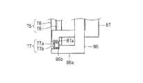
- One gripping portion 86 of the pair of gripping portions 86 and 87 is formed as a substantially rod-like member having a tip portion formed in a substantially L shape.
- the gripping portion 86 is supported in a hanging manner at the end of the insertion movable portion 82b on the opening direction side of the cavities 12 and 14, and the tip end of the gripping portion 86 is the cavity 12 to be inserted.
- , 14 are arranged in front of the openings.
- the front end portion of the gripping portion 86 is formed on a gripping end portion 86a formed so as to extend substantially horizontally from the front side portion thereof substantially orthogonal to the extending direction of the cavities 12 and 14.
- a substantially L-shaped gripping recess 86b is formed at the upper end of the gripping end 86a.
- the electric wire 22 of the terminal-attached electric wire 20 is arranged on the holding recess 86b.
- a terminal grip driving unit 84 is provided in the middle portion in the longitudinal direction of the grip unit 86.
- the terminal gripping drive unit 84 is configured by a linear actuator in the same manner as described above, and has a terminal gripping drive main body portion 84a and an advancing / retreating rod portion 84b that is driven back and forth with respect to the terminal gripping drive main body portion 84a.
- the terminal grip drive main body 84a is attached and fixed to one side portion of the intermediate portion in the longitudinal direction of the grip portion 86 with the forward / backward rod portion 84b facing downward.
- the other gripping portion 87 has a substantially L-shaped portion extending along one side portion of the vertically extending portion of the one gripping portion 86 and a lower end portion of the portion toward the gripping recess 86b. It has an intermediate connecting portion that extends and a gripping convex portion 87a that protrudes downward from the tip of the intermediate connecting portion. And the base end part of the said other grip part 87 is connected with the front-end
- the gripping concave part 86b and the gripping convex part 87a are configured to be capable of being driven close to and away from each other, and the electric wire 22 of the terminal-attached electric wire 20 can be disposed therebetween. Further, by driving the terminal gripping drive portion 84, the other gripping portion 87 is driven in the vertical direction so that the gripping concave portion 86b and the gripping convex portion 87a can arrange and release the electric wire 22 between them. It is configured to be switched between a non-gripping state that is open to a certain state and a gripping state that grips the electric wire 22 therebetween.
- a bar set portion 34 on which the electric wire holding bar 38 can be set is provided in a portion of the base plate 32 positioned in front of the openings of the cavities 12 and 14 (see FIG. 2).
- the electric wire holding bar 38 has a structure in which a plurality of electric wire clip portions 38b capable of holding the electric wires 22 are provided on a bar-shaped bar main body portion 38a.
- the bar set part 34 is configured to have a recessed part into which the end of the bar main body part 38a can be fitted, and by inserting both ends of the electric wire holding bar 38 into the recessed part of the bar set part 34, the electric wire holding bar 38 Is configured to be detachably held at the opening front position of the cavities 12 and 14.
- the said electric wire holding bar 38 is set to the bar set part 34, and the electric wire 20 with a terminal 20 used as insertion object is made into a pair. It is possible to stand by in the vicinity of the gripping portions 86 and 87 and the terminal insertion guide portion 76.
- FIG. 7 is a functional block diagram of the terminal insertion device 40.
- the terminal insertion device 40 includes an input unit 90a and a set completion switch 90b, and an overall control unit 92.
- the input unit 90a is configured by a plurality of switches, touch panels, or the like, and is configured to be able to accept input of insertion operations, various instructions relating to a pull-out test process, and various settings to the overall control unit 92.
- the set completion switch 90b is configured by a push switch or the like disposed in the vicinity of the pair of gripping portions 86 and 87 and the terminal insertion guide portion 76, and the operator manually sets the pair of gripping portions 86 and 87 and the terminals. After the terminal-equipped electric wire 20 is set in the insertion guide portion 76, an instruction to the effect that the setting is completed can be received.
- the overall control unit 92 is configured by a general programmable microcomputer including a CPU, a ROM such as a flash memory, and a RAM. A program for performing a terminal insertion process and a pull-out test, which will be described later, is created based on the input from the input unit 90a and stored in a ROM such as a flash memory.
- the overall control unit 92 includes a housing elevating drive mechanism unit 56, a common horizontal drive mechanism unit 66, a guide advance / retreat drive mechanism unit 71, a guide horizontal drive mechanism unit 72, a pair of guide elevating drive mechanism units 73, and an insertion unit.
- the overall control unit 92 has a function as an insertion operation control unit 93 that performs control to move the gripping units 86 and 87 forward and backward with respect to the cavities 12 and 14 and a determination unit 94 that performs a pull-out test at that time.
- the processing as the insertion operation control unit 93 and the determination unit 94 will be described in detail later.
- the insertion advance / retreat drive unit 82 is configured to be able to move and drive the terminal gripping drive unit 84 and the pair of gripping units 86 and 87 with a preset upper limit thrust. More specifically, the insertion advance / retreat drive unit 82 includes a screw shaft extending along the movement drive direction, a nut portion that is screwed to the screw shaft and integrated with the insertion advance / retreat movable portion 82b, and the screw shaft. And a motor 83a that rotationally drives the motor 83a.
- the motor 83a is configured to incorporate a kind of ball screw mechanism that moves the movable portion 82b for insertion and retraction by rotationally driving the motor 83a in both forward and reverse directions.
- the motor 83a is composed of a stepping motor or the like, and is drive-controlled through a drive circuit (not shown) under the control of the motor controller 83b. That is, when the overall control unit 92 instructs the motor controller 83b on the advance / retreat direction, the advance / retreat movement position, the movement speed, and the like of the insertion advance / retreat drive unit 82, the motor controller 83b controls the motor 83a through the drive circuit based on the command.
- Drive control of rotation direction that is, advance / retreat direction of insertion advance / retreat drive unit 82
- rotation amount that is, position of insertion advance / retreat drive unit 82
- rotation speed that is, movement speed of insertion advance / retreat drive unit 82
- the motor controller 83b is configured to be able to control the torque of the motor 83a by performing feedback control of the motor 83a based on the drive current of the motor 83a and the like. Further, when performing torque control of the motor 83a, the motor controller 83b is configured to be able to drive and control the motor 83a with a predetermined upper limit torque (that is, the upper limit thrust of the insertion advance / retreat drive unit 82). When the overall control unit 92 gives an operation command of the insertion advance / retreat drive unit 82 under a predetermined upper limit thrust condition to the motor controller 83b, the motor controller 83b determines a predetermined value according to the upper limit thrust based on the command. The motor 83a is driven and controlled under the upper limit torque condition.
- the insertion advancing / retreating drive unit 82 drives the gripping portions 86, 87 to move, if a force is applied to stop the gripping portions 86, 87 and a large load is applied to the insertion advancing / retreating driving unit 82, a predetermined load is applied.
- the insertion advancing / retreating drive unit 82 is controlled to operate with the upper limit thrust.
- the motor controller 83b outputs a signal to that effect to the overall control unit 92 during a period in which the thrust of the insertion advance / retreat driving unit 82 reaches a predetermined upper limit thrust.
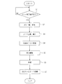
- FIG. 8 is a flowchart showing a terminal insertion process in the overall control unit 92
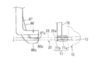
- FIGS. 9 to 16 are explanatory diagrams showing a terminal insertion operation by the terminal insertion device 40.
- FIG. 8 is a flowchart showing a terminal insertion process in the overall control unit 92
- FIGS. 9 to 16 are explanatory diagrams showing a terminal insertion operation by the terminal insertion device 40.
- the gripping recesses 86b and the gripping protrusions of the pair of gripping portions 86 and 87 are located at the opening front positions of the cavities 12 and 14 to be inserted. While the portion 87a is opened, the pair of split guide portions 78 are closed to form a hole-shaped insertion guide surface 77.
- the gripping concave portions 86b and the gripping convex portions 87a of the pair of gripping portions 86 and 87 and the insertion guide surface 77 of the terminal insertion guide portion 76 are disposed at the opening front positions of the cavities 12 and 14 to be inserted.
- the relative movement of the pair of gripping portions 86 and 87 and the terminal insertion guide portion 76 and the terminal insertion housing 10 includes an upward / downward movement operation of the terminal insertion housing 10 by the housing lifting / lowering drive mechanism portion 56 of the housing support mechanism portion 50. This is done by a horizontal movement operation by the pair of gripping portions 86 and 87 and the terminal insertion guide portion 76 by the common horizontal drive mechanism portion 66 of the common drive mechanism portion 62.
- step S1 the overall control unit 92 determines whether or not there is a set completion instruction from the set completion switch 90b. When it is determined that there is no set completion instruction, the process of step S1 is repeated, and when it is determined that there is a set completion instruction, the process proceeds to step S2.
- an operator who has the terminal-attached electric wire 20 inserts the terminal 26 at the end of the terminal-attached electric wire 20 into the insertion guide surface 77 from the side opposite to the cavity 12.
- the portion of the electric wire 22 on the nearer side than the terminal 26 is disposed between the gripping concave portion 86b and the gripping convex portion 87a.
- step S ⁇ b> 2 the overall control unit 92 gives a drive command to the split guide unit separation drive unit 75 to open the pair of split guide units 78, and the pair of gripping units 86, 86 to the terminal gripping drive unit 84.
- a drive command is given to close 87 and perform gripping.
- the electric wire 22 is gripped by the pair of gripping portions 86 and 87, and the position and posture restriction of the terminal 26 by the terminal insertion guide portion 76 is released.
- the overall control section 92 gives a drive command to the guide lifting drive mechanism section 73 so as to raise the terminal insertion guide section 76, and advances the pair of gripping sections 86 and 87 toward the cavities 12 and 14.
- a drive command is given to the advancing / retreating drive unit 82 for insertion so as to be moved. Accordingly, as shown in FIG. 14, the terminal insertion guide portion 76 is retracted upward, and the terminal-attached electric wire 20 held by the pair of holding portions 86 and 87 is pushed toward the cavities 12 and 14. 26 is pushed to a predetermined position in the cavities 12 and 14.
- step S4 after step S3, as shown in FIG. 5, the overall control unit 92 moves forward and backward for insertion so as to move the pair of gripping portions 86 and 87 backward from the cavities 12 and 14 under a predetermined upper limit thrust condition.
- a drive command is given to the unit 82.
- the predetermined upper limit thrust is a value set in advance according to the shape and size of the terminal. In other words, a predetermined pull-out force is normally defined for the terminals inserted and held in the connector so as not to come off during use.
- the predetermined upper limit thrust is a value set in advance in the overall control unit 92 for each type of terminal as a value that can clear the pull-out resistance, and the overall control unit 92 is currently performing an insertion operation.
- a drive command is given to the insertion advancing / retreating drive unit 82 so that the pair of gripping portions 86 and 87 are moved backward under the upper limit thrust condition set in accordance with the terminal. Then, a test is performed as to whether or not the terminal 26 does not come out of the cavity 12.
- the upper limit thrust is set as a thrust smaller than the rated thrust at the time of inserting the terminal 26 (for example, thrust of several percent of the rated thrust) according to the shape, size, etc. of the terminal 26. This pull-out test will be further described later.
- the overall control section 92 gives a drive command to the terminal gripping drive section 84 to open the pair of gripping sections 86 and 87 and release the gripping.
- grip of the electric wire 22 by a pair of holding parts 86 and 87 is cancelled
- the overall control unit 92 gives a drive command to the insertion advance / retreat drive unit 82 so as to retract the pair of gripping units 86, 87 from the cavities 12, 14.
- the pair of gripping portions 86 and 87 are retracted to their original positions while the terminal 26 is inserted and disposed in the cavities 12 and 14.
- the overall control unit 92 inserts a pair of gripping portions 86 and 87 and terminals into the housing elevating drive mechanism portion 56 of the housing support mechanism portion 50 and the common horizontal drive mechanism portion 66 of the common drive mechanism portion 62.
- a drive command is given so that the guide portion 76 is positioned in front of the opening of the cavities 12 and 14 to be inserted next.
- the positions of the cavities 12 and 14 to be inserted, the order of insertion, and the like are set and stored in advance by an operator or the like, and the overall control unit 92 follows the settings so that the housing elevating and lowering drive mechanism 56 and the common horizontal drive mechanism 66. Is controlled.
- the initial state is restored to the cavities 12 and 14 to be inserted next.
- the pair of division guide portions 78 are closed and the terminal insertion guide portion 76 is lowered.
- FIG. 17 is a flowchart showing the drawing test process in step S4 of FIG.
- step S11 After starting the pull-out test process, that is, in a state where the terminal 26 of the terminal-attached electric wire 20 gripped by the gripping portion 86 is inserted into the cavity 12, in step S11, the overall control portion 92 is inserted via the motor controller 83b.
- a reverse command with a predetermined upper limit thrust is given to the forward / backward drive unit 82.
- the conditions for the backward movement at this time are, for example, a moving speed of 70 mm / sec and an upper limit thrust of 8N.
- the insertion advancing / retreating drive part 82 moves the pair of gripping parts 86 and 87 backward under a predetermined upper limit thrust condition, and as a result, a pulling force acts on the terminal 26 inserted into the cavity 12. .
- step S12 the overall control unit 92 determines whether or not the upper limit thrust has been reached based on the output from the motor controller 83b. If it is determined that the upper limit thrust has been reached, the process proceeds to step S13. .
- step S13 the overall control unit 92 determines whether or not the upper limit thrust reaching time has passed the first determination time T1.
- the first determination time T1 is a time (for example, 100 msec) in which the influence of the external force is assumed to be eliminated to some extent after the start of the backward movement for the drawing test (for example, 100 msec).
- the input is set in the control unit 92. That is, immediately after the upper limit thrust is reached, the pair of gripping portions 86 and 87 sway, and therefore, the motor 83a is relatively affected by external force due to the sway.
- the value detected as the thrust corresponding to the torque of the motor 83a due to the influence of the external force or the like does not necessarily accurately reflect the pulling force actually acting on the terminal 26.
- step S13 if it is determined that the upper limit thrust reaching time has elapsed the first determination time T1, the process proceeds to step S14, where it is determined that the extraction test is acceptable. Thereafter, the process proceeds to step S6 shown in FIG. 8 to continue the migration process.
- step S13 determines whether the upper limit thrust reaching time has not elapsed the first determination time T1 (the upper limit thrust reaching state has been released before the elapse of time)
- the process proceeds to step S16 and the pull-out test fails. It is judged. If it is determined in step S16 that the pull-out test is unsuccessful, the operation of the apparatus 40 is stopped, a visual or audible warning is issued, and the operator is encouraged to eliminate defective insertions and correct the work. Good.
- the process may proceed to either step S14 or S16.
- step S12 determines whether the upper limit thrust has been reached. If it is determined in step S12 that the upper limit thrust has not been reached, the process proceeds to step S15.
- step S15 the overall control unit 92 determines whether or not the second determination time T2 has elapsed after the gripping units 86 and 87 start to retract. If it is determined that the second determination time T2 has not elapsed, the process returns to step S12, and the determination process of step S12 is repeated. On the other hand, if it is determined in step S15 that the second determination time T2 has elapsed, the process proceeds to step S16, and the pull-out test is determined to be unacceptable. If the elapsed time from the start of retraction of the gripping portions 86 and 87 is the same as the second determination time T2, the process may proceed to either step S12 or S16.
- FIG. 18 is a view showing the relationship between the elapsed time t after the start of retraction of the gripping portions 86 and 87 by the insertion advance / retreat drive unit 82 and the thrust (torque of the motor 83a) by the insertion advance / retreat drive unit 82.
- the terminal 26 When the terminal 26 is normally inserted into the cavity 12, the terminal 26 is maintained in the state of being inserted into the cavity 12 even if a pull-out test is performed. Therefore, as shown by a line L ⁇ b> 1 indicated by a solid line in FIG. 18. The thrust gradually increases and reaches the upper limit thrust F1 (time t1). The state where the upper limit thrust F1 has been reached is maintained for the first determination time T1, and when the time t2 is reached, it is determined that the pull-out test has passed (see steps S12, S13, and S13). On the other hand, as the state where the terminal 26 is inserted into the cavity 12 in an abnormal state, for example, the following two types are conceivable.
- the first is a case where the terminal 26 comes out of the cavity 12 immediately after the start of retraction
- the second is a case where the terminal 26 comes out of the cavity 12 after a large pulling force is applied after the start of retraction.
- a line L2 indicated by a two-dot chain line in FIG. 18 when the thrust rises to some extent, the terminal 26 comes out, so that the thrust does not reach the upper limit thrust.
- a pull-out test failure determination is made (see steps S15 and S16).
- the terminal 26 is removed soon after the thrust reaches the upper limit thrust, and the thrust decreases from the upper limit thrust before reaching the time t3. Resulting in. For this reason, the time when the upper limit thrust is reached is not maintained for the first determination time T1, and it is determined that the pull-out test is unacceptable (see steps S12, S13, and S16).
- the terminal insertion device 40 configured as described above, when the gripping portions 86 and 87 are moved backward from the cavities 12 and 14, based on the duration time of the extraction operation with the upper limit thrust according to the required extraction force. More specifically, in order to determine whether or not the pull-out test of the terminal 26 or the like is successful based on whether or not the predetermined first determination time T1 has elapsed, a stable period in which the influence of external force or the like is removed to some extent Thus, it is possible to determine whether or not the pull-out test of the terminal 26 and the like is successful, and the pull-out force test can be performed more accurately.
- the extraction test may be performed.
- the motor 83a or the like of the insertion advance / retreat drive unit 82 is provided with a predetermined torque limit and an output function at the time of torque limit, it is convenient in that the pull-out test can be performed using the function.
- the housing lifting / lowering drive mechanism 56 for moving the housing holding portion 52 up and down is provided, the terminal insertion housing 10 held by the housing holding portion 52 is moved up and down by driving the housing lifting / lowering driving mechanism 56.
- the plurality of cavities 12 and 14 and the gripping portions 86 and 87 can be relatively moved up and down to insert the terminals 26 of the terminal-attached electric wires 20 into the plurality of cavities 12 and 14 in the vertical direction.
- the grips 86 and 87 are horizontally moved by the drive of the common drive mechanism 62.
- the plurality of cavities 12 and 14 and the gripping portions 86 and 87 are relatively horizontally moved, and the insertion work of the terminal 26 of the terminal-equipped electric wire 20 to the plurality of cavities 12 and 14 in the horizontal direction is performed. Can be implemented.
- the insertion advance / retreat drive unit 82 mainly needs to move the relatively lightweight grips 86 and 87 forward and backward with respect to the cavity 12, so that the pulling force that actually acts on the terminal 26 and the like is applied to the insertion advance / retreat unit 82. It can be accurately reflected by the thrust of the drive unit 82 (torque of the motor 83a), and the pulling force test can be performed more accurately.
- a configuration in which the housing holding portion that holds the terminal insertion housing 10 is moved only in the horizontal direction a configuration in which the housing holding portion is moved in both the vertical direction and the horizontal direction, or the terminal insertion drive mechanism 80 is moved only in the vertical direction.
- terminal insertion device has been described in detail as described above, the above description is an example in all aspects, and the present invention is not limited thereto. It is understood that countless variations that are not illustrated can be envisaged without departing from the scope of the present invention.
Landscapes
- Engineering & Computer Science (AREA)
- Manufacturing & Machinery (AREA)
- Manufacturing Of Electrical Connectors (AREA)
Abstract
Description
Claims (4)
- 端子付電線の端子を、端子挿入ハウジングに形成されたキャビティに挿入するための端子挿入装置であって、
前記端子挿入ハウジングを保持するハウジング保持部と、
前記端子付電線の端部を把持及び把持解除可能な把持部と、
前記把持部を前記キャビティに対して進退駆動可能な挿入用進退駆動部と、
前記把持部により把持された前記端子付電線の端子を前記キャビティ内に挿入するように前記把持部を前記キャビティに向けて進出移動させ、前記把持部により把持された前記端子付電線の端子が前記キャビティ内に挿入された状態で、必要とされる引抜き力に応じた上限推力で前記把持部を前記キャビティから後退移動させる挿入動作制御部と、
前記把持部を前記キャビティから後退移動させる際に、前記必要とされる引抜き力に応じた上限推力による動作の継続時間に基づいて、端子の引抜きテストの合否を判定する判定部と、
を備える端子挿入装置。 - 請求項1記載の端子挿入装置であって、
前記判定部は、前記必要とされる引抜き力に応じた上限推力による動作の継続時間が予め設定された判定時間経過したか否かを判定し、前記継続時間が前記判定時間を経過したと判定されたときに、端子の引抜きテスト合格と判定する、端子挿入装置。 - 請求項1記載の端子挿入装置であって、
前記キャビティに対する前記端子付電線の挿入方向に対して略直交する方向に、前記ハウジング保持部を移動させるハウジング移動駆動機構部をさらに備える端子挿入装置。 - 請求項1記載の端子挿入装置であって、
前記挿入用進退駆動部は、前記把持部を支持した状態で進退駆動可能に構成され、
前記キャビティに対する前記端子付電線の挿入方向に対して略直交する方向に、前記挿入用駆動部を前記把持部と共に移動させる挿入用駆動部側移動駆動機構部をさらに備える端子挿入装置。
Priority Applications (1)
| Application Number | Priority Date | Filing Date | Title |
|---|---|---|---|
| CN2010800318300A CN102474063A (zh) | 2009-07-15 | 2010-03-24 | 端子插入装置 |
Applications Claiming Priority (2)
| Application Number | Priority Date | Filing Date | Title |
|---|---|---|---|
| JP2009-166823 | 2009-07-15 | ||
| JP2009166823A JP5326893B2 (ja) | 2009-07-15 | 2009-07-15 | 端子挿入装置 |
Publications (1)
| Publication Number | Publication Date |
|---|---|
| WO2011007601A1 true WO2011007601A1 (ja) | 2011-01-20 |
Family
ID=43449211
Family Applications (1)
| Application Number | Title | Priority Date | Filing Date |
|---|---|---|---|
| PCT/JP2010/055050 Ceased WO2011007601A1 (ja) | 2009-07-15 | 2010-03-24 | 端子挿入装置 |
Country Status (3)
| Country | Link |
|---|---|
| JP (1) | JP5326893B2 (ja) |
| CN (2) | CN102474063A (ja) |
| WO (1) | WO2011007601A1 (ja) |
Cited By (2)
| Publication number | Priority date | Publication date | Assignee | Title |
|---|---|---|---|---|
| EP3076499A4 (en) * | 2014-01-08 | 2016-11-23 | Sumitomo Wiring Systems | CONNECTION APPARATUS AND WIRING MODULE MANUFACTURING METHOD |
| EP3591771A3 (en) * | 2018-05-11 | 2020-02-12 | The Boeing Company | Apparatus and methods for contact insertion and retention testing |
Families Citing this family (6)
| Publication number | Priority date | Publication date | Assignee | Title |
|---|---|---|---|---|
| JP2012204102A (ja) * | 2011-03-24 | 2012-10-22 | Shin Meiwa Ind Co Ltd | 端子圧着装置 |
| JP5174265B2 (ja) * | 2012-06-19 | 2013-04-03 | 日本オートマチックマシン株式会社 | 端子挿入装置、ワイヤーハーネス製造装置、物品検出装置、及び、端子挿入方法、ワイヤーハーネス製造方法、物品検出方法 |
| CN104407398B (zh) * | 2014-12-22 | 2017-02-22 | 天津长城精益汽车零部件有限公司 | 一种线束用塑件内端子安装检测装置 |
| WO2018163260A1 (ja) * | 2017-03-06 | 2018-09-13 | 株式会社フジクラ | 端子挿入装置、ワイヤハーネスの製造方法 |
| CN108406251A (zh) * | 2018-05-09 | 2018-08-17 | 立讯精密工业(滁州)有限公司 | 套管组装设备 |
| JP7372294B2 (ja) * | 2021-09-27 | 2023-10-31 | 矢崎総業株式会社 | 端子挿入装置 |
Citations (2)
| Publication number | Priority date | Publication date | Assignee | Title |
|---|---|---|---|---|
| JPH05299150A (ja) * | 1992-04-21 | 1993-11-12 | Hirakawa Hewtec Kk | 電源コードと電気接続端子の接続強度の判定方法,及び判定装置 |
| JP2005142031A (ja) * | 2003-11-06 | 2005-06-02 | Furukawa Electric Co Ltd:The | 電線付端子の挿入装置 |
Family Cites Families (7)
| Publication number | Priority date | Publication date | Assignee | Title |
|---|---|---|---|---|
| US4750898A (en) * | 1987-04-30 | 1988-06-14 | Wang Laboratories, Inc. | Anti-tamper shroud for cable connector |
| JP3094891B2 (ja) * | 1996-02-16 | 2000-10-03 | 住友電装株式会社 | コネクタ検査装置 |
| JPH11260526A (ja) * | 1998-03-06 | 1999-09-24 | Yazaki Corp | 電線付端子挿入装置 |
| JP2004185852A (ja) * | 2002-11-29 | 2004-07-02 | Sumitomo Wiring Syst Ltd | ワイヤーハーネスの製造方法及び端子付電線の接続装置 |
| JP4351603B2 (ja) * | 2004-09-28 | 2009-10-28 | 矢崎総業株式会社 | 端子挿入装置 |
| JP4917418B2 (ja) * | 2006-12-14 | 2012-04-18 | タイコエレクトロニクスジャパン合同会社 | 端子挿入装置 |
| JP2008288191A (ja) * | 2007-04-16 | 2008-11-27 | Mitsubishi Cable Ind Ltd | 端子挿入補助装置 |
-
2009
- 2009-07-15 JP JP2009166823A patent/JP5326893B2/ja active Active
-
2010
- 2010-03-24 CN CN2010800318300A patent/CN102474063A/zh active Pending
- 2010-03-24 WO PCT/JP2010/055050 patent/WO2011007601A1/ja not_active Ceased
- 2010-03-24 CN CN201610069494.8A patent/CN105720449A/zh active Pending
Patent Citations (2)
| Publication number | Priority date | Publication date | Assignee | Title |
|---|---|---|---|---|
| JPH05299150A (ja) * | 1992-04-21 | 1993-11-12 | Hirakawa Hewtec Kk | 電源コードと電気接続端子の接続強度の判定方法,及び判定装置 |
| JP2005142031A (ja) * | 2003-11-06 | 2005-06-02 | Furukawa Electric Co Ltd:The | 電線付端子の挿入装置 |
Cited By (3)
| Publication number | Priority date | Publication date | Assignee | Title |
|---|---|---|---|---|
| EP3076499A4 (en) * | 2014-01-08 | 2016-11-23 | Sumitomo Wiring Systems | CONNECTION APPARATUS AND WIRING MODULE MANUFACTURING METHOD |
| EP3591771A3 (en) * | 2018-05-11 | 2020-02-12 | The Boeing Company | Apparatus and methods for contact insertion and retention testing |
| US11128086B2 (en) | 2018-05-11 | 2021-09-21 | The Boeing Company | Apparatus for contact insertion and retention testing |
Also Published As
| Publication number | Publication date |
|---|---|
| JP5326893B2 (ja) | 2013-10-30 |
| JP2011023195A (ja) | 2011-02-03 |
| CN105720449A (zh) | 2016-06-29 |
| CN102474063A (zh) | 2012-05-23 |
Similar Documents
| Publication | Publication Date | Title |
|---|---|---|
| JP5326893B2 (ja) | 端子挿入装置 | |
| JP5169996B2 (ja) | 端子挿入装置 | |
| US8286346B2 (en) | Method for inserting a terminal | |
| JP6542024B2 (ja) | 圧着接続部を製造するための方法および装置 | |
| KR101793879B1 (ko) | 와이어 클램프를 갖는 터미널 크림핑 기계 | |
| US11783969B2 (en) | Twisted wire producing apparatus and twisted wire producing method | |
| JP2011096659A (ja) | ワイヤのワイヤ端部を操作するための機器および方法 | |
| JP2013015623A (ja) | 光ファイバ融着接続機 | |
| JPH03274690A (ja) | 電線付端子のコネクタハウジングへの挿入方法および装置 | |
| CN111092394A (zh) | 芯线变形夹具和芯线变形方法 | |
| JP6648162B2 (ja) | Tig溶接装置 | |
| US20060063430A1 (en) | Terminal inserting apparatus | |
| JPS6052224A (ja) | ワイヤカット放電加工機のワイヤクランプ機構 | |
| CN103008862B (zh) | 铁芯顶杆的焊接装置 | |
| JP4089825B2 (ja) | 電線付端子の挿入装置 | |
| JP2010277852A (ja) | 端子圧着装置及び端子圧着方法 | |
| JP5088582B2 (ja) | 筒状部材挿入装置 | |
| JP2008282734A (ja) | 端子挿入装置 | |
| CN216133825U (zh) | 一种结构简单的继电器反峰抑制结构 | |
| JP4127453B2 (ja) | ワイヤ放電加工機 | |
| JP2009172655A (ja) | 電気抵抗溶接機 | |
| CN221405772U (zh) | 一种用于触点接触的检测治具 | |
| CN111711045A (zh) | 电缆自动压接装置 | |
| JP2023047916A (ja) | 端子挿入装置 | |
| CN210692836U (zh) | 一种电源连接器 |
Legal Events
| Date | Code | Title | Description |
|---|---|---|---|
| WWE | Wipo information: entry into national phase |
Ref document number: 201080031830.0 Country of ref document: CN |
|
| 121 | Ep: the epo has been informed by wipo that ep was designated in this application |
Ref document number: 10799663 Country of ref document: EP Kind code of ref document: A1 |
|
| WWE | Wipo information: entry into national phase |
Ref document number: 12012500095 Country of ref document: PH |
|
| NENP | Non-entry into the national phase |
Ref country code: DE |
|
| 122 | Ep: pct application non-entry in european phase |
Ref document number: 10799663 Country of ref document: EP Kind code of ref document: A1 |