WO2010147053A1 - 気相成長装置 - Google Patents
気相成長装置 Download PDFInfo
- Publication number
- WO2010147053A1 WO2010147053A1 PCT/JP2010/059906 JP2010059906W WO2010147053A1 WO 2010147053 A1 WO2010147053 A1 WO 2010147053A1 JP 2010059906 W JP2010059906 W JP 2010059906W WO 2010147053 A1 WO2010147053 A1 WO 2010147053A1
- Authority
- WO
- WIPO (PCT)
- Prior art keywords
- susceptor
- gear
- gear member
- members
- height adjusting
- Prior art date
- Legal status (The legal status is an assumption and is not a legal conclusion. Google has not performed a legal analysis and makes no representation as to the accuracy of the status listed.)
- Ceased
Links
Images






Classifications
-
- C—CHEMISTRY; METALLURGY
- C23—COATING METALLIC MATERIAL; COATING MATERIAL WITH METALLIC MATERIAL; CHEMICAL SURFACE TREATMENT; DIFFUSION TREATMENT OF METALLIC MATERIAL; COATING BY VACUUM EVAPORATION, BY SPUTTERING, BY ION IMPLANTATION OR BY CHEMICAL VAPOUR DEPOSITION, IN GENERAL; INHIBITING CORROSION OF METALLIC MATERIAL OR INCRUSTATION IN GENERAL
- C23C—COATING METALLIC MATERIAL; COATING MATERIAL WITH METALLIC MATERIAL; SURFACE TREATMENT OF METALLIC MATERIAL BY DIFFUSION INTO THE SURFACE, BY CHEMICAL CONVERSION OR SUBSTITUTION; COATING BY VACUUM EVAPORATION, BY SPUTTERING, BY ION IMPLANTATION OR BY CHEMICAL VAPOUR DEPOSITION, IN GENERAL
- C23C14/00—Coating by vacuum evaporation, by sputtering or by ion implantation of the coating forming material
- C23C14/22—Coating by vacuum evaporation, by sputtering or by ion implantation of the coating forming material characterised by the process of coating
- C23C14/50—Substrate holders
- C23C14/505—Substrate holders for rotation of the substrates
-
- C—CHEMISTRY; METALLURGY
- C23—COATING METALLIC MATERIAL; COATING MATERIAL WITH METALLIC MATERIAL; CHEMICAL SURFACE TREATMENT; DIFFUSION TREATMENT OF METALLIC MATERIAL; COATING BY VACUUM EVAPORATION, BY SPUTTERING, BY ION IMPLANTATION OR BY CHEMICAL VAPOUR DEPOSITION, IN GENERAL; INHIBITING CORROSION OF METALLIC MATERIAL OR INCRUSTATION IN GENERAL
- C23C—COATING METALLIC MATERIAL; COATING MATERIAL WITH METALLIC MATERIAL; SURFACE TREATMENT OF METALLIC MATERIAL BY DIFFUSION INTO THE SURFACE, BY CHEMICAL CONVERSION OR SUBSTITUTION; COATING BY VACUUM EVAPORATION, BY SPUTTERING, BY ION IMPLANTATION OR BY CHEMICAL VAPOUR DEPOSITION, IN GENERAL
- C23C16/00—Chemical coating by decomposition of gaseous compounds, without leaving reaction products of surface material in the coating, i.e. chemical vapour deposition [CVD] processes
- C23C16/44—Chemical coating by decomposition of gaseous compounds, without leaving reaction products of surface material in the coating, i.e. chemical vapour deposition [CVD] processes characterised by the method of coating
- C23C16/458—Chemical coating by decomposition of gaseous compounds, without leaving reaction products of surface material in the coating, i.e. chemical vapour deposition [CVD] processes characterised by the method of coating characterised by the method used for supporting substrates in the reaction chamber
- C23C16/4582—Rigid and flat substrates, e.g. plates or discs
- C23C16/4583—Rigid and flat substrates, e.g. plates or discs the substrate being supported substantially horizontally
- C23C16/4584—Rigid and flat substrates, e.g. plates or discs the substrate being supported substantially horizontally the substrate being rotated
-
- H—ELECTRICITY
- H10—SEMICONDUCTOR DEVICES; ELECTRIC SOLID-STATE DEVICES NOT OTHERWISE PROVIDED FOR
- H10P—GENERIC PROCESSES OR APPARATUS FOR THE MANUFACTURE OR TREATMENT OF DEVICES COVERED BY CLASS H10
- H10P72/00—Handling or holding of wafers, substrates or devices during manufacture or treatment thereof
- H10P72/04—Apparatus for manufacture or treatment
- H10P72/0431—Apparatus for thermal treatment
- H10P72/0434—Apparatus for thermal treatment mainly by convection
-
- H—ELECTRICITY
- H10—SEMICONDUCTOR DEVICES; ELECTRIC SOLID-STATE DEVICES NOT OTHERWISE PROVIDED FOR
- H10P—GENERIC PROCESSES OR APPARATUS FOR THE MANUFACTURE OR TREATMENT OF DEVICES COVERED BY CLASS H10
- H10P72/00—Handling or holding of wafers, substrates or devices during manufacture or treatment thereof
- H10P72/70—Handling or holding of wafers, substrates or devices during manufacture or treatment thereof for supporting or gripping
- H10P72/76—Handling or holding of wafers, substrates or devices during manufacture or treatment thereof for supporting or gripping using mechanical means, e.g. clamps or pinches
- H10P72/7604—Handling or holding of wafers, substrates or devices during manufacture or treatment thereof for supporting or gripping using mechanical means, e.g. clamps or pinches the wafers being placed on a susceptor, stage or support
- H10P72/7618—Handling or holding of wafers, substrates or devices during manufacture or treatment thereof for supporting or gripping using mechanical means, e.g. clamps or pinches the wafers being placed on a susceptor, stage or support characterised by a movable susceptor, stage or support, others than those only rotating on their own vertical axis, e.g. susceptors on a rotating carrousel
-
- H—ELECTRICITY
- H10—SEMICONDUCTOR DEVICES; ELECTRIC SOLID-STATE DEVICES NOT OTHERWISE PROVIDED FOR
- H10P—GENERIC PROCESSES OR APPARATUS FOR THE MANUFACTURE OR TREATMENT OF DEVICES COVERED BY CLASS H10
- H10P72/00—Handling or holding of wafers, substrates or devices during manufacture or treatment thereof
- H10P72/70—Handling or holding of wafers, substrates or devices during manufacture or treatment thereof for supporting or gripping
- H10P72/76—Handling or holding of wafers, substrates or devices during manufacture or treatment thereof for supporting or gripping using mechanical means, e.g. clamps or pinches
- H10P72/7604—Handling or holding of wafers, substrates or devices during manufacture or treatment thereof for supporting or gripping using mechanical means, e.g. clamps or pinches the wafers being placed on a susceptor, stage or support
- H10P72/7621—Handling or holding of wafers, substrates or devices during manufacture or treatment thereof for supporting or gripping using mechanical means, e.g. clamps or pinches the wafers being placed on a susceptor, stage or support characterised by supporting two or more semiconductor substrates
Definitions
- the present invention relates to a vapor phase growth apparatus, and more particularly, to a self-revolving vapor phase growth apparatus that vapor-grows a semiconductor thin film on a substrate surface while revolving the substrate.
- a vapor phase growth apparatus for vapor phase growth on a large number of substrates at once, a plurality of rotation susceptors are arranged in the circumferential direction of the outer periphery of the revolution susceptor, an external gear is provided on the outer periphery of the rotation susceptor, and the chamber is provided in the chamber.
- the fixed internal gear and the external gear are disengaged.
- the fixed internal gear and the external gear have to be manually engaged with each other in a predetermined state.
- the number of the rotating susceptors is large, it takes time and effort to check the engagement state.
- the rotation susceptor is greatly inclined, and there is a possibility that a large force acts on the gear and the gear is chipped.
- an object of the present invention is to provide a self-revolving vapor phase growth apparatus capable of automatically engaging an external gear and an internal gear.
- a first configuration of the vapor phase growth apparatus of the present invention includes a disc-shaped susceptor rotatably provided in a chamber, and a plurality of external gear members rotatably provided in the circumferential direction of the outer periphery of the susceptor.
- a vapor phase growth apparatus having a self-revolving mechanism including a ring-shaped fixed internal gear member having an internal gear meshing with the external gear member, at least one of the susceptor and the internal gear member is connected to the external gear member.
- the gear member and the internal gear member are formed so as to be movable in the rotational axis direction between a meshed position where the gear member meshes with each other and a non-engaged position where both gear members are separated in the rotational axis direction, and at least of both gear members When both gear members move from the non-engaged position to the meshed position on the tooth side surface of one of the gear members, they contact the tooth side surface of the other gear member.
- a guide slope for guiding the gear member on the engagement state is provided.
- the second configuration of the vapor phase growth apparatus of the present invention is a disk-shaped susceptor rotatably provided in the chamber, and a plurality of external gear members rotatably provided in the circumferential direction of the outer periphery of the susceptor.
- a vapor phase growth apparatus having a self-revolving mechanism comprising a ring-shaped fixed internal gear member having an internal gear meshing with the external gear member, an upper surface of a shaft member for supporting and rotating the susceptor and a center of the susceptor
- a pair of upper and lower susceptor height adjusting members are provided opposite to each other, and the susceptor height adjusting members are opposed to the opposing surface of each susceptor height adjusting member toward the opposing susceptor height adjusting members.
- Protruding projecting surfaces are respectively formed in the circumferential direction, and when the projecting surfaces are brought into contact with each other, the susceptor is supported at a higher position than during film formation, and the outer gear member and the inner gear member are engaged with each other.
- Protruding dimensions The susceptor and the outer gear member supported in a position at the time of deposition and the internal gear member is formed so as to have a predetermined meshing when brought into contact with small projecting faces.
- a third configuration of the vapor phase growth apparatus of the present invention includes a disk-shaped susceptor rotatably provided in the chamber, and a plurality of external gear members rotatably provided in the circumferential direction of the outer periphery of the susceptor.
- a vapor phase growth apparatus having a self-revolving mechanism including a ring-shaped fixed internal gear member having an internal gear meshing with the external gear member, at least one of the susceptor and the internal gear member is connected to the external gear member.
- the gear member and the internal gear member are formed so as to be movable in the rotational axis direction between a meshed position where the gear member meshes with each other and a non-engaged position where both gear members are separated in the rotational axis direction, and at least of both gear members When both gear members move from the non-engaged position to the meshed position on the tooth side surface of one of the gear members, they contact the tooth side surface of the other gear member.
- a guide slope for guiding the gear member into the meshing state is provided, and a pair of upper and lower susceptor height adjusting members are opposed to each other between the upper surface of the shaft member that supports and rotates the susceptor and the lower surface of the central portion of the susceptor.
- the susceptor height adjusting member is provided such that projecting surfaces having different projecting dimensions are formed on the opposing surfaces of the respective susceptor height adjusting members in the circumferential direction, and projecting surfaces having larger projecting dimensions are brought into contact with each other.
- the susceptor is supported at a higher position than when the film is formed, and the external gear member and the internal gear member are engaged with each other by the guide slope, so that the projecting surface having a large projecting dimension and the projecting surface having a small projecting dimension are brought into contact with each other.
- the external gear member and the internal gear member are formed in a predetermined meshing state by supporting the susceptor at the position during film formation.
- the guide inclined surface Both gear members can be guided to mesh.
- the external gear member provided in a freely rotating state with respect to the susceptor is slightly rotated in either direction, so that both the gear members are reliably guided in the meshed state. Therefore, it is also possible to automate the attachment / detachment of the susceptor by eliminating the manual engagement work.
- the susceptor height adjustment member supports the susceptor at a higher position than during film formation, so that the external gear member and the internal gear are Even if the member is in a non-engagement state, the external gear member is not greatly inclined, and the gear is not chipped.
- the external gear member and the internal gear member change from the non-engagement state to the meshing state, so the susceptor height adjustment member holds the susceptor.
- the external gear member and the internal gear member can be brought into a predetermined meshing state, and the position of the susceptor in the chamber can be set to a predetermined height.
- the third configuration of the vapor phase growth apparatus of the present invention it is possible to more reliably prevent the gear from being chipped, and to further shift the external gear member and the internal gear member from the non-meshing state to the meshing state. It can be done reliably.
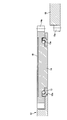
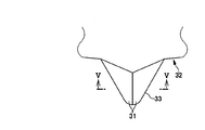
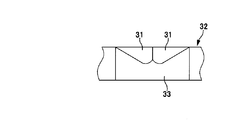
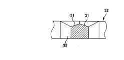
- FIG. 1 is a cross-sectional front view showing a first embodiment of a vapor phase growth apparatus of the present invention. It is a cross-sectional front view of the principal part which shows the state which the susceptor and the external gear member moved relatively to the rotation axis direction. It is a top view which shows one shape example of the guide slope provided in the tooth
- FIG. 5 is a VV cross-sectional view of FIG. 3. It is a top view which shows the other example of a shape of the guide slope provided in the tooth
- FIG. 5 is a VV cross-sectional view of FIG. 3. It is a top view which shows the other example of a shape of the guide slope provided in the tooth
- FIG. 8 is a cross-sectional view taken along the line VIII-VIII in FIG. 6. It is a cross-sectional front view which shows the 2nd example of a vapor phase growth apparatus of this invention. It is a sectional front view showing a susceptor height adjusting member. It is a top view of the susceptor height adjustment member provided in the upper surface of the shaft member. It is a bottom view of the susceptor height adjustment member provided in the center part lower surface of a susceptor. It is explanatory drawing which shows the state which supported the susceptor in the position higher than the time of film-forming by the susceptor height adjustment member. It is explanatory drawing which shows the state which supported the susceptor in the position at the time of film-forming by the susceptor height adjustment member.
- the vapor phase growth apparatus shown in FIGS. 1 to 8 shows a first embodiment of the present invention.
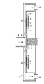
- a disk-shaped susceptor 12 is rotatably provided in a chamber 11, and ring-shaped bearings are respectively provided in a plurality of circular openings 12 a formed in the circumferential direction of the outer periphery of the susceptor 12.
- a member 13 an external gear member (spinning susceptor) 14 rotatably mounted on each bearing member 13 via a plurality of rolling members (balls) 13 a, and a ring shape meshing with the external gear member 14
- a flow channel 18 for introducing gas.
- a shaft member 19 for rotating the susceptor 12 is provided at the center lower portion of the susceptor 12, and a gas introduction portion 20 for introducing a raw material gas into the flow channel 18 at the center upper portion of the flow channel 18.
- a plurality of gas discharge portions 21 are provided on the outer periphery of the flow channel 18.
- the lower surface of the bearing member 13, the lower surface of the external gear member 14, and the lower surface of the susceptor 12 are flush with each other.
- the upper surface of the outer peripheral portion of the member 14 and the upper surface of the substrate 16 and the upper surface of the susceptor 12 are formed to be flush with each other.
- One or both of the susceptor 12 and the fixed internal gear member 15 are provided so as to be movable in the direction of the rotation axis (vertical direction). As shown in FIG.
- the bearing member 13 and the external gear member 14 are located above the fixed internal gear member 15 together with the susceptor 12, and the external gear 14a of the external gear member 14 and the internal gear 15a of the fixed internal gear member 15 are shown in FIG.
- the position of the meshing state shown in FIG. 1 is changed to the position of the non-meshing state shown in FIG.
- the guide slope 31 shown in FIG. 3 to FIG. 5 has one side surface of the tooth 33 of the gear member 32 as a mountain-shaped slope, and this guide slope 31 is connected to the external gear 14 a of the external gear member 14.
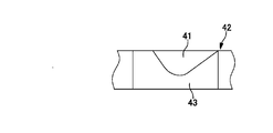
- the guide slope 41 shown in FIGS. 6 to 8 is one in which one side surface of the tooth 43 of the gear member 42 is entirely inclined, and the opposing external gear 14a and internal gear 15a are A guide slope 41 that is inclined in the same direction when the two come into contact with each other is provided.
- the external gear member 14 is slightly rotated so that the external gear 14a moves along the inclination of both guide slopes 41, and the teeth of the external gear 14a become the internal gear.
- the gears 14a and 15a enter a predetermined meshing state by entering between the teeth of 15a.
- the susceptor 12 and the fixed internal gear on which the bearing member 13 and the external gear member 14 are mounted are provided.
- the member 15 is assembled, even if the teeth of the external gear 14a and the teeth of the internal gear 15a are out of mesh with each other, the teeth of the external gear 14a and the teeth of the internal gear 15a are automatically moved by the guide slope. In addition, a predetermined meshing state can be ensured.
- the gears 14a and 15a can be meshed more smoothly. In rotating the susceptor 12, for example, the susceptor 12 may be rotated about 2 to 3 times at a rotation speed slower than the rotation speed during film formation, or may be rotated only in one direction.
- each component can be appropriately set according to the size of the vapor phase growth apparatus, the number of substrates processed at one time, the size of the substrate, the type of source gas, etc.
- the susceptor transport mechanism is optional.
- the guide slope may be provided only on the side surface of one of the teeth, and the guide slope may be a curved surface.
- the vapor phase growth apparatus shown in FIGS. 9 to 14 shows a second embodiment of the present invention.
- the same components as those of the vapor phase growth apparatus shown in the first embodiment are denoted by the same reference numerals, and detailed description thereof is omitted.
- the vapor phase growth apparatus shown in the present embodiment basically has the same configuration as the vapor growth apparatus shown in the first embodiment.
- the disc-shaped susceptor 12 rotatably provided in the chamber 11 is provided with a pair of upper and lower susceptor height adjusting members 51, 61 made of quartz provided on the upper surface of the shaft member 19 and the lower surface of the central portion of the susceptor 12. And supported by the shaft member 19.
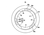
- the lower susceptor height adjusting member 51 provided on the upper surface of the shaft member 19 includes three protruding portions 52 protruding upward toward the upper susceptor height adjusting member 61 facing each other in the circumferential direction of the upper surface outer peripheral portion, Stepped concavo-convex portions 54 in which three sets of three concave portions 53 formed between the protruding portions 52 are alternately formed are provided at intervals of 120 degrees. Further, a ring-shaped protrusion 55 protruding upward toward the upper susceptor height adjusting member 61 is formed on the inner peripheral side of the stepped uneven portion 54, and a lower portion is formed on the inner peripheral side of the ring-shaped protrusion 55.
- Screw holes 57 for inserting eight screws 56 for attaching the susceptor height adjusting member 51 to the upper surface of the shaft member 19 are formed at eight positions in the circumferential direction at equal intervals.
- the lower susceptor height adjusting member 51 is made of quartz, and the shaft member 19 is made of carbon. Thus, in order to join the members of different materials, both are mechanically joined.
- the upper susceptor height adjusting member 61 provided on the lower surface of the central portion of the susceptor 12 is formed with a circular opening 62 having an inner diameter corresponding to the outer diameter of the ring-shaped protruding portion 55 at the central portion.
- a ring-shaped fitting protrusion 63 having an outer diameter corresponding to the inner diameter of the fitting recess 12 b formed on the lower surface of the center portion of the susceptor 12 is provided on the outer peripheral upper surface of 62 so as to protrude upward.
- a stepped uneven portion 64 corresponding to the protrusion 52 and the recess 53 of the lower susceptor height adjusting member 51 is formed on the back surface of the fitting protrusion 63.
- a ring-shaped projecting portion 65 having an inner diameter corresponding to the outer diameter of the lower susceptor height adjusting member 51 is provided on the outer periphery of the stepped uneven portion 64 so as to protrude downward.
- a flange 66 for attaching the upper susceptor height adjusting member 61 to the lower surface of the central portion of the susceptor 12 is provided on the outer periphery.
- the upper susceptor height adjusting member 61 is made of quartz, and the susceptor 12 is made of SiC-coated carbon.
- the upper susceptor height adjusting member 61 is provided with the flange 66 and mechanically joined using, for example, screw holes and screws (not shown).
- the stepped concavo-convex portion 64 of the upper susceptor height adjusting member 61 includes a concave portion 67 formed at a predetermined interval in the circumferential direction, and a first protruding portion protruding downward in two steps toward the lower susceptor height adjusting member 51.
- Three sets of stepped protrusions 68 having 68a and second protrusions 68b and anti-rotation protrusions 69 protruding downward from the protrusions 68 are provided at intervals of 120 degrees in the circumferential direction.
- the size of the recess 67 of the upper susceptor height adjustment member 61 is large enough to accommodate the protrusion 52 of the lower susceptor height adjustment member 51, and the size of the recess 53 of the lower susceptor height adjustment member 51.
- the size of the upper susceptor height adjusting member 61 is large enough to accommodate the protruding portion 68 and the non-rotating convex portion 69.
- the projecting heights of the first projecting portion 68a and the second projecting portion 68b in the projecting portion 68 are set to appropriate heights according to the thickness of the external gear member 14 and the fixed internal gear member 15 and the presence or absence of the guide slope. Is set.
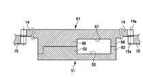
- the protrusions 52, 68 a, 68 b and the rotation preventing projection 69 are arranged so that the shaft member 19 is forwardly moved in the forward direction with the susceptor 12 placed on the upper surface of the shaft member 19 via the susceptor height adjusting members 51, 61 ( When the film is rotated in the direction of rotation during film formation, the protruding portions 52, 68a, 68b and the rising portions (steps) of the non-rotating convex portion 69 come into contact with each other to transmit the rotation of the shaft member 19 to the susceptor 12. It has a function to do.
- the protrusion 52 of the lower susceptor height adjusting member 51 is provided.
- the front end surface of the protrusion 68 of the upper susceptor height adjustment member 61 in this embodiment, one of the front end surfaces of the first protrusion 68a and the second protrusion 68b. To do.
- the susceptor 12 is supported at a position higher than the height during film formation with respect to the shaft member 19.
- the external gear member (spinning susceptor) 14 positioned on the outer peripheral portion of the susceptor 12 becomes higher than the fixed internal gear member 15, and the external gear A state where the lower portion of the member 14 and the upper portion of the fixed internal gear member 15 are slightly engaged, for example, 1 to 2 mm can be achieved. Therefore, even if the external gear member 14 and the internal gear member 15 are not engaged with each other and the external gear 14a of the external gear member 14 rides on the internal gear 15a of the internal gear member 15, the external gear member 14 is not greatly inclined, and the gear is not chipped.
- the susceptor 12 is rotated, for example, by rotating about one rotation at a rotation speed slower than the rotation speed at the time of film formation, on the internal gear 15a.
- the tooth of the external gear 14a that has been in the riding state falls between the teeth of the internal gear 15a, so that the external gear member 14 and the internal gear member 15 are engaged with each other.
- the susceptor height adjusting members 51 and 61 are provided with protrusions that prevent rotation in the reverse direction. Since the anti-rotation projection is not provided, the shaft member 19 rotates in the reverse direction with the susceptor 12 hardly rotating.
- the protrusion 52 of the lower susceptor height adjustment member 51 is accommodated in the recess 67 of the upper susceptor height adjustment member 61, and the protrusion 68 of the upper susceptor height adjustment member 61 and The anti-rotation protrusion 69 is accommodated in the recess 53 of the lower susceptor height adjustment member 51.
- the susceptor 12 will be in the state supported by the position corresponding to the height at the time of film-forming, and it will be in the fixed internal gear member 15.
- the external gear member 14 is lowered, the external gear member 14 and the fixed internal gear member 15 are brought into a meshing state during a predetermined film formation.
- the external gear member 14 and the fixed internal gear member 15 are portions of the guide slope when the susceptor 12 is supported at a higher position than during film formation. By setting the height of the susceptor 12 so as to engage with each other, the external gear member 14 and the fixed internal gear member 15 can be more reliably engaged with each other.
- the projecting portion may be only one step, and the anti-rotation convex portion may be provided on either of the upper and lower susceptor height adjusting members.
- Screw 57 ... Screw hole, 61 ... Upper susceptor height Length adjusting member 62 ... circular opening 63 63 fitting protrusion 64 64 step-like uneven part 65 ... ring-like protrusion 66 66 flange 67 recessed part 68 ... protrusion 68a ... first protrusion 68b ... second protrusion 69 ... Ri stop convex portion
Landscapes
- Chemical & Material Sciences (AREA)
- Chemical Kinetics & Catalysis (AREA)
- Engineering & Computer Science (AREA)
- Materials Engineering (AREA)
- Mechanical Engineering (AREA)
- Metallurgy (AREA)
- Organic Chemistry (AREA)
- General Chemical & Material Sciences (AREA)
- Chemical Vapour Deposition (AREA)
- Physical Vapour Deposition (AREA)
Abstract
Description
Claims (3)
- チャンバー内に回転可能に設けられた円盤状のサセプタと、該サセプタの外周部周方向に回転可能に設けられた複数の外歯車部材と、該外歯車部材に噛合する内歯車を備えたリング状の固定内歯車部材とを備えた自公転機構を有する気相成長装置において、前記サセプタ及び前記内歯車部材の少なくともいずれか一方を、前記外歯車部材と前記内歯車部材とが互いに噛み合う噛み合い状態の位置と両歯車部材が回転軸線方向に離間した非噛み合い状態の位置とに、回転軸線方向に移動可能に形成するとともに、両歯車部材の少なくともいずれか一方の歯車部材の歯側面に、両歯車部材が前記非噛み合い状態の位置から前記噛み合い状態の位置へと移動したときに、他方の歯車部材の歯側面に当接して両歯車部材を前記噛み合い状態にガイドするためのガイド斜面を設けた気相成長装置。
- チャンバー内に回転可能に設けられた円盤状のサセプタと、該サセプタの外周部周方向に回転可能に設けられた複数の外歯車部材と、該外歯車部材に噛合する内歯車を備えたリング状の固定内歯車部材とを備えた自公転機構を有する気相成長装置において、前記サセプタを支持して回転させる軸部材の上面とサセプタの中央部下面との間に上下一対のサセプタ高さ調節部材が対向して設けられ、該サセプタ高さ調節部材は、各サセプタ高さ調節部材の対向面の周方向に、対向するサセプタ高さ調節部材に向かって突出する突出部と該突出部の間に形成される凹部とを交互に複数組形成し、前記一対のサセプタ高さ調節部材の突出部先端面同士を当接させたときに前記サセプタを成膜時より高い位置に支持して前記外歯車部材と前記内歯車部材とが僅かに噛み合った状態とし、前記一対のサセプタ高さ調節部材の突出部を前記凹部内に位置させたときに前記サセプタを成膜時の位置に支持して前記外歯車部材と前記内歯車部材とが所定の噛み合い状態となる気相成長装置。
- チャンバー内に回転可能に設けられた円盤状のサセプタと、該サセプタの外周部周方向に回転可能に設けられた複数の外歯車部材と、該外歯車部材に噛合する内歯車を備えたリング状の固定内歯車部材とを備えた自公転機構を有する気相成長装置において、前記サセプタ及び前記内歯車部材の少なくともいずれか一方を、前記外歯車部材と前記内歯車部材とが互いに噛み合う噛み合い状態の位置と両歯車部材が回転軸線方向に離間した非噛み合い状態の位置とに、回転軸線方向に移動可能に形成するとともに、両歯車部材の少なくともいずれか一方の歯車部材の歯側面に、両歯車部材が前記非噛み合い状態の位置から前記噛み合い状態の位置へと移動したときに、他方の歯車部材の歯側面に当接して両歯車部材を前記噛み合い状態にガイドするためのガイド斜面を設け、前記サセプタを支持して回転させる軸部材の上面とサセプタの中央部下面との間に上下一対のサセプタ高さ調節部材が対向して設けられ、該サセプタ高さ調節部材は、各サセプタ高さ調節部材の対向面の周方向に、対向するサセプタ高さ調節部材に向かって突出する突出部と該突出部の間に形成される凹部とを交互に複数組形成し、前記一対のサセプタ高さ調節部材の突出部先端面同士を当接させたときに前記サセプタを成膜時より高い位置に支持して前記外歯車部材と前記内歯車部材とが前記ガイド斜面で噛み合った状態とし、前記一対のサセプタ高さ調節部材の突出部を前記凹部内に位置させたときに前記サセプタを成膜時の位置に支持して前記外歯車部材と前記内歯車部材とが所定の噛み合い状態となる気相成長装置。
Priority Applications (4)
| Application Number | Priority Date | Filing Date | Title |
|---|---|---|---|
| CN201080027286.2A CN102804339B (zh) | 2009-06-19 | 2010-06-11 | 气相生长装置 |
| JP2011519748A JP5613159B2 (ja) | 2009-06-19 | 2010-06-11 | 気相成長装置 |
| US13/379,077 US20120103265A1 (en) | 2009-06-19 | 2010-06-11 | Vapor phase growth apparatus |
| US14/988,351 US9765427B2 (en) | 2009-06-19 | 2016-01-05 | Vapor phase growth apparatus |
Applications Claiming Priority (2)
| Application Number | Priority Date | Filing Date | Title |
|---|---|---|---|
| JP2009146740 | 2009-06-19 | ||
| JP2009-146740 | 2009-06-19 |
Related Child Applications (2)
| Application Number | Title | Priority Date | Filing Date |
|---|---|---|---|
| US13/379,077 A-371-Of-International US20120103265A1 (en) | 2009-06-19 | 2010-06-11 | Vapor phase growth apparatus |
| US14/988,351 Division US9765427B2 (en) | 2009-06-19 | 2016-01-05 | Vapor phase growth apparatus |
Publications (1)
| Publication Number | Publication Date |
|---|---|
| WO2010147053A1 true WO2010147053A1 (ja) | 2010-12-23 |
Family
ID=43356371
Family Applications (1)
| Application Number | Title | Priority Date | Filing Date |
|---|---|---|---|
| PCT/JP2010/059906 Ceased WO2010147053A1 (ja) | 2009-06-19 | 2010-06-11 | 気相成長装置 |
Country Status (6)
| Country | Link |
|---|---|
| US (2) | US20120103265A1 (ja) |
| JP (1) | JP5613159B2 (ja) |
| KR (1) | KR101650839B1 (ja) |
| CN (1) | CN102804339B (ja) |
| TW (1) | TWI527089B (ja) |
| WO (1) | WO2010147053A1 (ja) |
Cited By (6)
| Publication number | Priority date | Publication date | Assignee | Title |
|---|---|---|---|---|
| US20130298836A1 (en) * | 2011-02-03 | 2013-11-14 | Tn Emc Ltd. | Vapor phase growth apparatus |
| CN103834926A (zh) * | 2012-11-22 | 2014-06-04 | 上海法德机械设备有限公司 | 真空镀膜工件转台 |
| WO2014196323A1 (ja) * | 2013-06-06 | 2014-12-11 | イビデン株式会社 | ウエハキャリアおよびこれを用いたエピタキシャル成長装置 |
| EP2828886A4 (en) * | 2012-03-20 | 2015-07-29 | Veeco Instr Inc | CODED WAFER CARRIER |
| JP2016139663A (ja) * | 2015-01-26 | 2016-08-04 | 大陽日酸株式会社 | 気相成長装置 |
| JP2021511666A (ja) * | 2018-01-23 | 2021-05-06 | アイクストロン、エスイー | サセプタを駆動シャフトに接続するための装置 |
Families Citing this family (2)
| Publication number | Priority date | Publication date | Assignee | Title |
|---|---|---|---|---|
| JP2015056635A (ja) * | 2013-09-13 | 2015-03-23 | 株式会社東芝 | 気相成長装置及び気相成長方法 |
| DE102018126862A1 (de) * | 2018-10-26 | 2020-04-30 | Oerlikon Surface Solutions Ag, Pfäffikon | Werkstückträgereinrichtung und Beschichtungsanordnung |
Citations (2)
| Publication number | Priority date | Publication date | Assignee | Title |
|---|---|---|---|---|
| JP2004525056A (ja) * | 2001-02-07 | 2004-08-19 | エムコア・コーポレイション | 化学蒸着によりウェハ上にエピタキシャル層を成長させる装置および方法 |
| JP2007266121A (ja) * | 2006-03-27 | 2007-10-11 | Hitachi Cable Ltd | 気相成長装置 |
Family Cites Families (10)
| Publication number | Priority date | Publication date | Assignee | Title |
|---|---|---|---|---|
| JPH0630552U (ja) * | 1992-09-22 | 1994-04-22 | カルソニック株式会社 | 歯車装置 |
| JPH10219447A (ja) * | 1997-02-12 | 1998-08-18 | Fujitsu Ltd | 気相成長装置 |
| US6068441A (en) * | 1997-11-21 | 2000-05-30 | Asm America, Inc. | Substrate transfer system for semiconductor processing equipment |
| JP4537566B2 (ja) * | 2000-12-07 | 2010-09-01 | 大陽日酸株式会社 | 基板回転機構を備えた成膜装置 |
| US6592675B2 (en) * | 2001-08-09 | 2003-07-15 | Moore Epitaxial, Inc. | Rotating susceptor |
| JP2003065402A (ja) * | 2001-08-28 | 2003-03-05 | Sumitomo Heavy Ind Ltd | 単純遊星歯車構造 |
| US6776849B2 (en) * | 2002-03-15 | 2004-08-17 | Asm America, Inc. | Wafer holder with peripheral lift ring |
| JP4470680B2 (ja) * | 2004-10-12 | 2010-06-02 | 日立電線株式会社 | 気相成長装置 |
| JP2007042899A (ja) * | 2005-08-03 | 2007-02-15 | Hitachi Cable Ltd | 気相成長装置 |
| JP2007243060A (ja) * | 2006-03-10 | 2007-09-20 | Taiyo Nippon Sanso Corp | 気相成長装置 |
-
2010
- 2010-06-11 WO PCT/JP2010/059906 patent/WO2010147053A1/ja not_active Ceased
- 2010-06-11 JP JP2011519748A patent/JP5613159B2/ja active Active
- 2010-06-11 US US13/379,077 patent/US20120103265A1/en not_active Abandoned
- 2010-06-11 KR KR1020127000943A patent/KR101650839B1/ko active Active
- 2010-06-11 CN CN201080027286.2A patent/CN102804339B/zh active Active
- 2010-06-18 TW TW099119845A patent/TWI527089B/zh active
-
2016
- 2016-01-05 US US14/988,351 patent/US9765427B2/en active Active
Patent Citations (2)
| Publication number | Priority date | Publication date | Assignee | Title |
|---|---|---|---|---|
| JP2004525056A (ja) * | 2001-02-07 | 2004-08-19 | エムコア・コーポレイション | 化学蒸着によりウェハ上にエピタキシャル層を成長させる装置および方法 |
| JP2007266121A (ja) * | 2006-03-27 | 2007-10-11 | Hitachi Cable Ltd | 気相成長装置 |
Cited By (8)
| Publication number | Priority date | Publication date | Assignee | Title |
|---|---|---|---|---|
| US20130298836A1 (en) * | 2011-02-03 | 2013-11-14 | Tn Emc Ltd. | Vapor phase growth apparatus |
| EP2828886A4 (en) * | 2012-03-20 | 2015-07-29 | Veeco Instr Inc | CODED WAFER CARRIER |
| US9816184B2 (en) | 2012-03-20 | 2017-11-14 | Veeco Instruments Inc. | Keyed wafer carrier |
| CN103834926A (zh) * | 2012-11-22 | 2014-06-04 | 上海法德机械设备有限公司 | 真空镀膜工件转台 |
| WO2014196323A1 (ja) * | 2013-06-06 | 2014-12-11 | イビデン株式会社 | ウエハキャリアおよびこれを用いたエピタキシャル成長装置 |
| JP2016139663A (ja) * | 2015-01-26 | 2016-08-04 | 大陽日酸株式会社 | 気相成長装置 |
| JP2021511666A (ja) * | 2018-01-23 | 2021-05-06 | アイクストロン、エスイー | サセプタを駆動シャフトに接続するための装置 |
| JP7266608B2 (ja) | 2018-01-23 | 2023-04-28 | アイクストロン、エスイー | サセプタを駆動シャフトに接続するための装置 |
Also Published As
| Publication number | Publication date |
|---|---|
| US9765427B2 (en) | 2017-09-19 |
| US20120103265A1 (en) | 2012-05-03 |
| US20160130695A1 (en) | 2016-05-12 |
| KR101650839B1 (ko) | 2016-08-24 |
| KR20120034101A (ko) | 2012-04-09 |
| CN102804339B (zh) | 2015-01-14 |
| JPWO2010147053A1 (ja) | 2012-12-06 |
| JP5613159B2 (ja) | 2014-10-22 |
| CN102804339A (zh) | 2012-11-28 |
| TWI527089B (zh) | 2016-03-21 |
| TW201110198A (en) | 2011-03-16 |
Similar Documents
| Publication | Publication Date | Title |
|---|---|---|
| JP5613159B2 (ja) | 気相成長装置 | |
| JP5436043B2 (ja) | 気相成長装置 | |
| US20190249298A1 (en) | Film forming apparatus | |
| JP2007243060A (ja) | 気相成長装置 | |
| US20120160170A1 (en) | Vapor phase growth apparatus | |
| TW201628120A (zh) | 晶圓承載裝置 | |
| JP5432041B2 (ja) | 気相成長装置 | |
| KR20140005163A (ko) | 기상 성장 장치 | |
| JP5139107B2 (ja) | 気相成長装置 | |
| TWI656233B (zh) | 單晶圓處理裝置及其操作方法、傳送方法與準直器 | |
| JP5292963B2 (ja) | 成膜装置およびそれを用いた製造方法 | |
| JP5144328B2 (ja) | 気相成長装置 | |
| JP2006128561A (ja) | 基板回転機構およびそれを備えた成膜装置 | |
| JP2008308747A (ja) | 気相成長装置および気相成長方法 | |
| JP2009099770A (ja) | 気相成長装置 | |
| CN114651319B (zh) | 配备热孔的基板处理装置 | |
| JP2013219217A (ja) | 気相成長装置 | |
| JP6661437B2 (ja) | 気相成長装置 | |
| JP2017226891A (ja) | 成膜装置およびそれを用いて成膜された基板の製造方法 | |
| JP2013098484A (ja) | サセプタ及びこれを用いた半導体製造装置 |
Legal Events
| Date | Code | Title | Description |
|---|---|---|---|
| WWE | Wipo information: entry into national phase |
Ref document number: 201080027286.2 Country of ref document: CN |
|
| 121 | Ep: the epo has been informed by wipo that ep was designated in this application |
Ref document number: 10789428 Country of ref document: EP Kind code of ref document: A1 |
|
| WWE | Wipo information: entry into national phase |
Ref document number: 2011519748 Country of ref document: JP |
|
| NENP | Non-entry into the national phase |
Ref country code: DE |
|
| WWE | Wipo information: entry into national phase |
Ref document number: 13379077 Country of ref document: US |
|
| ENP | Entry into the national phase |
Ref document number: 20127000943 Country of ref document: KR Kind code of ref document: A |
|
| 122 | Ep: pct application non-entry in european phase |
Ref document number: 10789428 Country of ref document: EP Kind code of ref document: A1 |