WO2010146970A1 - 排気構造、プラズマ処理装置及び方法 - Google Patents
排気構造、プラズマ処理装置及び方法 Download PDFInfo
- Publication number
- WO2010146970A1 WO2010146970A1 PCT/JP2010/058733 JP2010058733W WO2010146970A1 WO 2010146970 A1 WO2010146970 A1 WO 2010146970A1 JP 2010058733 W JP2010058733 W JP 2010058733W WO 2010146970 A1 WO2010146970 A1 WO 2010146970A1
- Authority
- WO
- WIPO (PCT)
- Prior art keywords
- gate valve
- vacuum vessel
- pendulum
- vacuum
- opening
- Prior art date
- Legal status (The legal status is an assumption and is not a legal conclusion. Google has not performed a legal analysis and makes no representation as to the accuracy of the status listed.)
- Ceased
Links
Images




Classifications
-
- C—CHEMISTRY; METALLURGY
- C23—COATING METALLIC MATERIAL; COATING MATERIAL WITH METALLIC MATERIAL; CHEMICAL SURFACE TREATMENT; DIFFUSION TREATMENT OF METALLIC MATERIAL; COATING BY VACUUM EVAPORATION, BY SPUTTERING, BY ION IMPLANTATION OR BY CHEMICAL VAPOUR DEPOSITION, IN GENERAL; INHIBITING CORROSION OF METALLIC MATERIAL OR INCRUSTATION IN GENERAL
- C23C—COATING METALLIC MATERIAL; COATING MATERIAL WITH METALLIC MATERIAL; SURFACE TREATMENT OF METALLIC MATERIAL BY DIFFUSION INTO THE SURFACE, BY CHEMICAL CONVERSION OR SUBSTITUTION; COATING BY VACUUM EVAPORATION, BY SPUTTERING, BY ION IMPLANTATION OR BY CHEMICAL VAPOUR DEPOSITION, IN GENERAL
- C23C16/00—Chemical coating by decomposition of gaseous compounds, without leaving reaction products of surface material in the coating, i.e. chemical vapour deposition [CVD] processes
- C23C16/44—Chemical coating by decomposition of gaseous compounds, without leaving reaction products of surface material in the coating, i.e. chemical vapour deposition [CVD] processes characterised by the method of coating
- C23C16/4412—Details relating to the exhausts, e.g. pumps, filters, scrubbers, particle traps
-
- C—CHEMISTRY; METALLURGY
- C23—COATING METALLIC MATERIAL; COATING MATERIAL WITH METALLIC MATERIAL; CHEMICAL SURFACE TREATMENT; DIFFUSION TREATMENT OF METALLIC MATERIAL; COATING BY VACUUM EVAPORATION, BY SPUTTERING, BY ION IMPLANTATION OR BY CHEMICAL VAPOUR DEPOSITION, IN GENERAL; INHIBITING CORROSION OF METALLIC MATERIAL OR INCRUSTATION IN GENERAL
- C23C—COATING METALLIC MATERIAL; COATING MATERIAL WITH METALLIC MATERIAL; SURFACE TREATMENT OF METALLIC MATERIAL BY DIFFUSION INTO THE SURFACE, BY CHEMICAL CONVERSION OR SUBSTITUTION; COATING BY VACUUM EVAPORATION, BY SPUTTERING, BY ION IMPLANTATION OR BY CHEMICAL VAPOUR DEPOSITION, IN GENERAL
- C23C16/00—Chemical coating by decomposition of gaseous compounds, without leaving reaction products of surface material in the coating, i.e. chemical vapour deposition [CVD] processes
- C23C16/44—Chemical coating by decomposition of gaseous compounds, without leaving reaction products of surface material in the coating, i.e. chemical vapour deposition [CVD] processes characterised by the method of coating
- C23C16/52—Controlling or regulating the coating process
-
- F—MECHANICAL ENGINEERING; LIGHTING; HEATING; WEAPONS; BLASTING
- F16—ENGINEERING ELEMENTS AND UNITS; GENERAL MEASURES FOR PRODUCING AND MAINTAINING EFFECTIVE FUNCTIONING OF MACHINES OR INSTALLATIONS; THERMAL INSULATION IN GENERAL
- F16K—VALVES; TAPS; COCKS; ACTUATING-FLOATS; DEVICES FOR VENTING OR AERATING
- F16K51/00—Other details not peculiar to particular types of valves or cut-off apparatus
- F16K51/02—Other details not peculiar to particular types of valves or cut-off apparatus specially adapted for high-vacuum installations
Definitions
- the present invention relates to an exhaust structure, a plasma processing apparatus, and a method for exhausting the inside of a vacuum vessel.
- An exhaust port is provided at the bottom of the vacuum vessel, a vacuum pump such as a turbo molecular pump is provided directly below the exhaust port, and the atmosphere in the vacuum vessel is uniformly evacuated to improve the uniformity of process processing, It is known as a prior art (patent documents 1 and 2). Japanese Patent Laid-Open No. 9-167762 JP 2002-208584 A
- a pressure control valve is used between the vacuum vessel and the vacuum pump to control the pressure in the vacuum vessel.
- a pendulum type gate valve has been used in order to perform efficient exhaustion by a turbo molecular pump with an increase in the substrate diameter.
- FIG. 4 A cross-sectional view of a conventional plasma processing apparatus having such a configuration is shown in FIG. 4, and its outline and problems will be described.
- a plasma CVD (Chemical Vapor Deposition) apparatus is shown and described.
- FIG. 4 illustration of a plasma generation mechanism, a gas supply mechanism, a substrate support structure, and the like is omitted.
- a conventional plasma processing apparatus 30 includes a cylindrical vacuum chamber 31 that is evacuated inside, a mounting table 32 that is placed inside the vacuum chamber 31 and on which a substrate 33 is placed, and a connection. Via a member 34, it is connected to the lower part of the vacuum chamber 31 and controls the pressure inside the vacuum chamber 31, and is connected to the lower part of the pendulum gate valve 35, and the atmosphere inside the vacuum chamber 31 is changed.
- a turbo molecular pump (Turbo Molecular Pump; hereinafter referred to as TMP) 37 is provided.
- the connecting member 34 is attached to the lower part of the vacuum chamber 31, the pendulum gate valve 35 is attached to the flange 34c of the connecting member 34 by a bolt 36 inserted from above, and the TMP 37 is inserted from below.
- the flange of the TMP 37 itself is attached to the pendulum type gate valve 35 by the bolt 36.
- a roughing pipe 38 is connected to the port 31 a on the side wall of the vacuum chamber 31, and a roughing vacuum pump 42 is connected via a valve 39 and an exhaust pipe 41. It is connected.
- the exhaust pipe 41 is connected to the exhaust port of the TMP 37 via the valve 40.
- the substrate 33 is mounted on the mounting table 32, a desired gas is supplied into the vacuum chamber 31, and the opening 35 a of the pendulum gate valve 35 is provided by a pressure control device (not shown).
- the substrate 33 is subjected to a desired plasma treatment by controlling the pressure inside the vacuum chamber 31 by controlling the opening ratio of the substrate 33b by the valve body 35b and generating plasma in the vacuum chamber 31.
- FIG. 5 is a cross-sectional view taken along line BB in FIG.
- the connecting member 34 so that the center of the opening 34 a of the connecting member 34 and the center of the opening 35 a of the pendulum gate valve 35 coincide with the axial center Cc of the cylindrical vacuum chamber 31.
- the pendulum type gate valve 35 is disposed, and the center of the connection portion of the TMP 37 is also disposed so as to coincide with the axial center Cc.
- the opening 35a of the pendulum gate valve 35 when it is arranged so as to have the above positional relationship, when the opening 35a of the pendulum gate valve 35 is fully opened, the atmosphere in the vacuum chamber 31 can be exhausted uniformly. However, when controlling the inside of the vacuum chamber 31 to a desired pressure, the opening 35a is not fully opened, and normally, a part of the opening 35a is closed by the valve body 35b, and the opening ratio is controlled. Thus, the desired pressure is controlled.
- the opening area M of the opening 35a in the pendulum gate valve 35 changes like a total solar eclipse due to the movement of the circular valve body 35b with respect to the circular opening 35a. Yes.
- the opening region M has a crescent shape that is biased toward one side of the opening 35a.
- the area center Mc is naturally not coincident with the axis center Cc. Therefore, during the actual process, the vacuum chamber 31 is not uniformly exhausted and is unevenly exhausted, which may adversely affect the process.
- the pendulum type gate valve 35 is used, the following problems are caused due to its structure.
- the pendulum type gate valve 35 is provided with a standby portion 35e of the valve body 35b.
- the valve body 35c is turned on. It is moved to the position 35e (see the dotted line portion in the figure).
- the maintenance of valve body 35b is attained by removing standby part 35e in flange 35d. Therefore, for maintenance, it is desirable that the standby unit 35 e be disposed outside the side wall of the vacuum chamber 31.
- the size (diameter) of the vacuum chamber 31 has increased with the recent increase in the substrate diameter.
- the center Cc of the vacuum chamber 31 and the center of the opening 35a of the pendulum gate valve 35 coincide with each other. If it arrange
- the diameter of the opening of the TMP or the pendulum type gate valve is increased in accordance with the diameter of the vacuum chamber, the height of the TMP or the pendulum type gate valve is increased, so that it is necessary to increase the substrate transfer height. Increasing the height of the entire apparatus according to the transport height should be avoided from an ergonomic point of view when handling the substrate.
- the standby portion 35e is disposed at a position accessible from the outside, but among the bolts 36 for attaching the pendulum gate valve 35 to the connecting member 34, the bolt 36 on the opposite side of the standby portion 35e. Is located in the back of the processing apparatus, and the bolt 36 is difficult to tighten and remove.
- the pendulum type gate valve 35 and the TMP 37 are arranged directly under the vacuum chamber 31, the roughing piping 38 and the valve 39 must be connected to the side wall of the vacuum chamber 31, and the maintenance performance is reduced. In addition, it was not efficient in terms of effective use of space.
- the present invention has been made in view of the above problems, and an object of the present invention is to provide an exhaust structure, a plasma processing apparatus, and a method that enable uniform exhaust and improve maintainability.
- An exhaust structure according to a first invention for solving the above-described problem is as follows. While supplying a desired gas into the cylindrical vacuum vessel, the pressure in the vacuum vessel is adjusted using a pendulum gate valve attached to the lower portion of the vacuum vessel and a vacuum pump attached to the lower portion of the pendulum gate valve. And an exhaust structure used in a processing apparatus for performing a desired processing on a processing object placed in the vacuum vessel, The pendulum is configured such that the center of the opening of the pendulum type gate valve is fully open with respect to the axial center of the vacuum vessel in the opening direction of the valve body that opens and closes the opening of the pendulum type gate valve. A type gate valve is attached to the vacuum vessel.
- An exhaust structure according to a second invention for solving the above-described problem is While supplying a desired gas into the cylindrical vacuum vessel, the pressure in the vacuum vessel is adjusted using a pendulum gate valve attached to the lower portion of the vacuum vessel and a vacuum pump attached to the lower portion of the pendulum gate valve. And an exhaust structure used in a processing apparatus for performing a desired processing on a processing object placed in the vacuum vessel, The pendulum type gate valve is attached to the vacuum vessel so that the center of the area of the opening region at the center value of the recommended use rate of the opening rate of the pendulum type gate valve coincides with the axial center of the vacuum vessel. And
- An exhaust structure according to a third invention for solving the above-described problem is In the exhaust structure according to the first or second invention, An exhaust pipe and a valve for another vacuum pump are provided below the vacuum vessel adjacent to the side of the pendulum gate valve.
- a plasma processing apparatus for solving the above-mentioned problems is as follows.
- the pendulum is configured such that the center of the opening of the pendulum type gate valve is fully open with respect to the axial center of the vacuum vessel in the opening direction of the valve body that opens and closes the opening of the pendulum type gate valve.
- a type gate valve is attached to the vacuum vessel.
- a plasma processing apparatus for solving the above-described problems is A cylindrical vacuum vessel in which a desired gas is supplied; a pendulum gate valve attached to a lower portion of the vacuum vessel; and a vacuum pump attached to a lower portion of the pendulum gate valve, the pendulum type
- the pendulum type gate valve is attached to the vacuum vessel so that the center of the area of the opening region at the center value of the recommended use rate of the opening rate of the pendulum type gate valve coincides with the axial center of the vacuum vessel.
- a plasma processing apparatus for solving the above-described problems is In the plasma processing apparatus according to the fourth or fifth invention, An exhaust pipe and a valve for another vacuum pump are provided below the vacuum vessel adjacent to the side of the pendulum gate valve.
- a plasma processing method for solving the above-described problem is A plasma processing method using the plasma processing apparatus according to any one of the fourth to sixth inventions, Supplying gas into the vacuum vessel; Using the pressure control valve and the vacuum pump to control the pressure in the vacuum vessel, Generating a plasma of the gas, A plasma treatment is performed on the substrate placed in the vacuum vessel.
- the pendulum type gate valve is attached to the vacuum vessel so that the center of the opening of the pendulum type gate valve is eccentric in the opening direction of the valve body with respect to the axial center of the vacuum vessel. Therefore, compared to the conventional exhaust structure, that is, the case where the center of the vacuum vessel and the center of the pendulum gate valve opening are arranged so as to coincide with each other, the exhaust flow during processing is more It becomes uniform.
- the stand for the pendulum gate valve to be removed during maintenance and the bolts for attaching the pendulum gate valve to the vacuum vessel are more outward than conventional ones. Maintenance will be facilitated.
- the pendulum type gate valve is eccentrically arranged in the vacuum container so that the area center of the opening region at the center value of the recommended use value of the opening ratio of the pendulum type gate valve coincides with the axial center of the vacuum container. Since it is attached, the flow of exhaust during processing becomes more uniform as compared with the conventional exhaust structure. In addition, as a result of eccentrically attaching the pendulum gate valve to the vacuum vessel, the stand for the pendulum gate valve to be removed during maintenance and the bolts for attaching the pendulum gate valve to the vacuum vessel are more outward than conventional ones. Maintenance will be facilitated.
- the exhaust pipe to the other vacuum pump is provided at the lower part of the vacuum vessel adjacent to the side of the pendulum type gate valve, so that the space inside the processing apparatus can be used efficiently.
- access to the exhaust pipe is easier than in the prior art, and maintenance is improved.
- a process having a relatively high pressure for example, a plasma cleaning, for example, At this time, the process is performed with a more uniform flow of exhaust gas, and plasma cleaning can be performed uniformly without bias. As a result, waste of gas used is reduced and damage to the inner surface of the chamber due to plasma is also reduced.
- FIG. 2 is a cross-sectional view taken along line AA in FIG. 1. It is a perspective view which shows the modification of the connection member shown in FIG. It is sectional drawing of the conventional plasma processing apparatus.
- FIG. 5 is a cross-sectional view taken along line BB in FIG. 4.
- a plasma CVD apparatus is illustrated here as an example, it is applicable not only to a plasma CVD apparatus but also to a plasma etching apparatus, and further, an apparatus that requires uniform evacuation in a vacuum vessel. Any other processing apparatus can be applied.
- Example 1 1 and 2 are sectional views showing an example of an embodiment of an exhaust structure according to the present invention
- FIG. 1 shows an exhaust structure in a plasma CVD apparatus
- FIG. 2 shows a line AA in FIG. It is arrow sectional drawing.
- illustration of a plasma generation mechanism, a gas supply mechanism, and the like is omitted.
- a plasma processing apparatus 10 of this embodiment includes a cylindrical vacuum chamber (vacuum container) 11 in which a desired gas is supplied and the internal pressure is controlled, and a vacuum chamber 11. Is attached to the lower part of the vacuum chamber 11 via a connection table 14 and a mounting table 12 on which a substrate (processing object) 13 to be subjected to a desired process is placed. It has a pendulum type gate valve 15 that controls the pressure, and a TMP (turbo molecular pump) 17 that is attached to the lower part of the pendulum type gate valve 15 and exhausts the atmosphere inside the vacuum chamber 11.
- the mounting table 12 has a cylindrical shape and the lower part thereof is securely supported by the side wall of the vacuum chamber 11, but the illustration thereof is omitted here.
- the connecting member 14 is attached to the lower part of the vacuum chamber 11, the pendulum gate valve 15 is attached to the flange 14c of the connecting member 14 by a bolt 16 inserted from above, and the TMP 17 is The flange of the TMP 17 itself is attached to the pendulum type gate valve 15 by the bolt 16 inserted from above.
- the pendulum gate valve 15 is eccentrically attached to the vacuum chamber 11. Specifically, as shown in FIG. 2, the pendulum gate valve 15 is arranged so that the axial center Cc of the cylindrical vacuum chamber 11 and the area center Mc of the opening region M of the pendulum gate valve 15 coincide. ing.
- the opening area M naturally changes depending on the opening ratio of the pendulum type gate valve 15, but in this embodiment, the center value of the recommended opening ratio (10% to 50%) of the pendulum type gate valve 15 is 30%.
- the area center Mc of the opening area M is obtained on the basis of the opening area M, and the pendulum gate valve 15 is arranged eccentrically so that the axis center Cc and the area center Mc coincide.
- the center Gc when the opening 15a of the pendulum gate valve 15 is fully opened is decentered with respect to the axial center Cc of the vacuum chamber 11 in the opening direction D of the valve body 15b that opens and closes the opening 15a.
- the center of the connection portion of the TMP 17 is disposed so as to coincide with the center of the opening 15 a of the pendulum type gate valve 15.
- the opening ratio of the pendulum type gate valve 15 is controlled in the vicinity of 30% and the inside of the vacuum chamber 11 is controlled to a desired pressure
- the atmosphere in the vacuum chamber 31 is changed. It is possible to exhaust uniformly.
- the inside of the vacuum chamber 11 is controlled to a desired pressure with an aperture ratio far from 30%, it is slightly non-uniform compared to when the aperture ratio is 30%, but even in that case, it is more uniform than the conventional case. Can be exhausted.
- This effect is noticeable in a process with a relatively high pressure vacuum.
- plasma cleaning in a plasma CVD apparatus is performed with a relatively high degree of vacuum.
- there has been a bias in plasma cleaning and in order to perform predetermined cleaning, excessive gas is consumed, or a part of the cleaning is performed excessively, and plasma damage may occur.
- the vacuum chamber 11 and the mounting table 12 are subjected to uniform plasma cleaning. As a result, useless gas is used and damage due to plasma is caused.
- the maintenance frequency can be reduced and the service life of the parts can be extended.
- the opening 14a of the connecting member 14 is also eccentrically provided, and this eccentric direction is also eccentric to the opening direction D of the valve body 15b.
- a space is created in the opposite side portion that is eccentric, and a port 14b for the roughing exhaust pipe 18 is provided in the lower part of the vacuum chamber 11 adjacent to the side of the pendulum type gate valve 15, Even if the port is on the side wall of the vacuum chamber 11, it is possible to arrange the roughing pipe 18, the valve (valve) 19, etc. directly under the vacuum chamber 11.
- the roughing pipe 18 is connected not to the side wall of the vacuum chamber 11 but to the port 14 b at the bottom thereof, and the valve 19 and the exhaust pipe 21 are connected.
- the exhaust pipe 21 is connected to the exhaust port of the TMP 17 via the valve 20.
- the roughing pipe 18, the valve 19 and the like can be arranged directly under the vacuum chamber 11, and can be efficiently arranged together with the TMP 17 and the like in the internal space of the processing apparatus.
- the pendulum type gate valve 15 is eccentrically connected, the standby portion 15e of the valve body 15b is arranged on the outer side from the side wall of the vacuum chamber 11 as compared with the conventional case. Therefore, the position of the flange 15d is also on the outer side, and access to the standby unit 15e is facilitated. Therefore, by rotating the valve body 15b around the rotating shaft 15c and moving the valve body 15b to the position of the standby portion 15e, maintenance to the valve body 15b becomes possible, and maintenance performance for the pendulum gate valve 15 is improved. It can also be improved.
- the fact that the pendulum type gate valve 15 is eccentrically connected means that the bolt 16 on the opposite side of the standby portion 15e is arranged on the front side as compared with the conventional case, and the bolt 16 is tightened and removed. It is also possible to reduce the difficulty.
- the connecting member 14 has a simple structure in which an eccentric opening 14a is provided in a circular flat plate-like member.
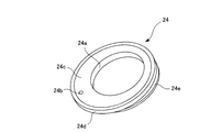
- the connecting member shown in FIG. It is good also as a structure like 24.
- the connecting member 24 has an eccentric opening 24a and a port 24b for roughing piping, like the connecting member 14, but extends from the opening portion of the upper portion of the connecting member 24 to the opening 24a.
- an inclined portion 24c is formed, and the air is smoothly exhausted toward the opening 24a.
- the upper flange 24 d is connected to the vacuum chamber 11 and the lower flange 24 e is connected to the pendulum gate valve 15.
- the present invention is suitable for a plasma processing apparatus and method such as plasma CVD and plasma etching used for manufacturing a semiconductor device.
- the present invention is not limited to manufacturing a semiconductor device as long as the apparatus has an exhaust port in the lower part of a vacuum vessel.
- the present invention can be applied to an apparatus for manufacturing other products.
Landscapes
- Chemical & Material Sciences (AREA)
- Engineering & Computer Science (AREA)
- Mechanical Engineering (AREA)
- General Chemical & Material Sciences (AREA)
- Chemical Kinetics & Catalysis (AREA)
- Materials Engineering (AREA)
- Metallurgy (AREA)
- Organic Chemistry (AREA)
- General Engineering & Computer Science (AREA)
- Drying Of Semiconductors (AREA)
- Chemical Vapour Deposition (AREA)
Abstract
Description
振り子式ゲート弁35には、弁体35bのメンテナンスのため、弁体35bの待機部35eが設けられており、回転軸35cを中心に弁体35bを回転させることにより、弁体35cを待機部35eの位置へ移動させている(図中の点線部分参照)。そして、フランジ35dにおいて、待機部35eを取り外すことにより、弁体35bのメンテナンスが可能となる。従って、メンテナンスのためには、待機部35eは、真空チャンバ31の側壁より外側に配置することが望ましい。ところが、近年の基板の大口径化に伴い、真空チャンバ31の大きさ(直径)は大きくなってきた。TMPや振り子式ゲート弁の開口部の径は、十分な排気能力があれば大きくする必要性が無いため、真空チャンバ31の軸中心Ccと振り子式ゲート弁35の開口部35aの中心とを一致するように配置すると、待機部35eの一部が真空チャンバ31の側壁より内側に入り込んでしまい、メンテナンス性の低下を招いていた。TMPや振り子式ゲート弁の開口部の径を真空チャンバの直径に合わせて大きくした場合は、TMPや振り子式ゲート弁の高さが高くなるため、基板の搬送高さも高くする必要が生じる。搬送高さに応じて装置全体の高さを上げることは、基板を扱う上で人間工学的な見地から避けるべきである。
円筒状の真空容器内に所望のガスを供給すると共に、前記真空容器の下部に取り付けた振り子式ゲート弁と前記振り子式ゲート弁の下部に取り付けた真空ポンプを用いて、前記真空容器内の圧力を制御して、前記真空容器内に載置した処理対象物に所望の処理を施す処理装置に用いられる排気構造であって、
前記真空容器の軸中心に対して、前記振り子式ゲート弁の開口部の全開時の中心が、前記振り子式ゲート弁の開口部の開閉を行う弁体の開方向に偏心するように、前記振り子式ゲート弁を前記真空容器に取り付けたことを特徴とする。
円筒状の真空容器内に所望のガスを供給すると共に、前記真空容器の下部に取り付けた振り子式ゲート弁と前記振り子式ゲート弁の下部に取り付けた真空ポンプを用いて、前記真空容器内の圧力を制御して、前記真空容器内に載置した処理対象物に所望の処理を施す処理装置に用いられる排気構造であって、
前記真空容器の軸中心に、前記振り子式ゲート弁の開口率の使用推奨値の中心値における開口領域の面積中心が一致するように、前記振り子式ゲート弁を前記真空容器に取り付けたことを特徴とする。
上記第1又は第2の発明に記載の排気構造において、
前記振り子式ゲート弁の側方に隣接して、前記真空容器の下部に他の真空ポンプへの排気配管や弁を設けたことを特徴とする。
所望のガスが内部に供給される円筒状の真空容器と、前記真空容器の下部に取り付けた振り子式ゲート弁と、前記振り子式ゲート弁の下部に取り付けた真空ポンプとを有し、前記振り子式ゲート弁及び前記真空ポンプを用いて前記真空容器内の圧力を制御し、前記ガスのプラズマを生成して、前記真空容器内に載置した基板にプラズマ処理を施すプラズマ処理装置において、
前記真空容器の軸中心に対して、前記振り子式ゲート弁の開口部の全開時の中心が、前記振り子式ゲート弁の開口部の開閉を行う弁体の開方向に偏心するように、前記振り子式ゲート弁を前記真空容器に取り付けたことを特徴とする。
所望のガスが内部に供給される円筒状の真空容器と、前記真空容器の下部に取り付けた振り子式ゲート弁と、前記振り子式ゲート弁の下部に取り付けた真空ポンプとを有し、前記振り子式ゲート弁及び前記真空ポンプを用いて前記真空容器内の圧力を制御し、前記ガスのプラズマを生成して、前記真空容器内に載置した基板にプラズマ処理を施すプラズマ処理装置において、
前記真空容器の軸中心に、前記振り子式ゲート弁の開口率の使用推奨値の中心値における開口領域の面積中心が一致するように、前記振り子式ゲート弁を前記真空容器に取り付けたことを特徴とする。
上記第4又は第5の発明に記載のプラズマ処理装置において、
前記振り子式ゲート弁の側方に隣接して、前記真空容器の下部に他の真空ポンプへの排気配管や弁を設けたことを特徴とする。
上記第4~第6の発明のいずれか1つに記載のプラズマ処理装置を用いたプラズマ処理方法であって、
前記真空容器内にガスを供給し、
前記圧力制御弁及び前記真空ポンプを用いて、前記真空容器内の圧力を制御し、
前記ガスのプラズマを生成し、
前記真空容器内に載置した基板にプラズマ処理を施すことを特徴とする。
11 真空チャンバ
12 載置台
13 基板
14、24 接続部材
15 振り子式ゲート弁
16 ボルト
17 ターボ分子ポンプ(TMP)
18 粗引き配管
19、20 バルブ
21 排気配管
22 真空ポンプ
図1、図2は、本発明に係る排気構造の実施形態の一例を示す断面図であり、図1は、プラズマCVD装置における排気構造を図示し、図2は、図1のA-A線矢視断面図である。なお、図1、図2において、プラズマ発生機構、ガス供給機構等の図示は省略している。
Claims (7)
- 円筒状の真空容器内に所望のガスを供給すると共に、前記真空容器の下部に取り付けた振り子式ゲート弁と前記振り子式ゲート弁の下部に取り付けた真空ポンプを用いて、前記真空容器内の圧力を制御して、前記真空容器内に載置した処理対象物に所望の処理を施す処理装置に用いられる排気構造であって、
前記真空容器の軸中心に対して、前記振り子式ゲート弁の開口部の全開時の中心が、前記振り子式ゲート弁の開口部の開閉を行う弁体の開方向に偏心するように、前記振り子式ゲート弁を前記真空容器に取り付けたことを特徴とする排気構造。 - 円筒状の真空容器内に所望のガスを供給すると共に、前記真空容器の下部に取り付けた振り子式ゲート弁と前記振り子式ゲート弁の下部に取り付けた真空ポンプを用いて、前記真空容器内の圧力を制御して、前記真空容器内に載置した処理対象物に所望の処理を施す処理装置に用いられる排気構造であって、
前記真空容器の軸中心に、前記振り子式ゲート弁の開口率の使用推奨値の中心値における開口領域の面積中心が一致するように、前記振り子式ゲート弁を前記真空容器に取り付けたことを特徴とする排気構造。 - 請求項1又は請求項2に記載の排気構造において、
前記振り子式ゲート弁の側方に隣接して、前記真空容器の下部に他の真空ポンプへの排気配管や弁を設けたことを特徴とする排気構造。 - 所望のガスが内部に供給される円筒状の真空容器と、前記真空容器の下部に取り付けた振り子式ゲート弁と、前記振り子式ゲート弁の下部に取り付けた真空ポンプとを有し、前記振り子式ゲート弁及び前記真空ポンプを用いて前記真空容器内の圧力を制御し、前記ガスのプラズマを生成して、前記真空容器内に載置した基板にプラズマ処理を施すプラズマ処理装置において、
前記真空容器の軸中心に対して、前記振り子式ゲート弁の開口部の全開時の中心が、前記振り子式ゲート弁の開口部の開閉を行う弁体の開方向に偏心するように、前記振り子式ゲート弁を前記真空容器に取り付けたことを特徴とするプラズマ処理装置。 - 所望のガスが内部に供給される円筒状の真空容器と、前記真空容器の下部に取り付けた振り子式ゲート弁と、前記振り子式ゲート弁の下部に取り付けた真空ポンプとを有し、前記振り子式ゲート弁及び前記真空ポンプを用いて前記真空容器内の圧力を制御し、前記ガスのプラズマを生成して、前記真空容器内に載置した基板にプラズマ処理を施すプラズマ処理装置において、
前記真空容器の軸中心に、前記振り子式ゲート弁の開口率の使用推奨値の中心値における開口領域の面積中心が一致するように、前記振り子式ゲート弁を前記真空容器に取り付けたことを特徴とするプラズマ処理装置。 - 請求項4又は請求項5に記載のプラズマ処理装置において、
前記振り子式ゲート弁の側方に隣接して、前記真空容器の下部に他の真空ポンプへの排気配管や弁を設けたことを特徴とするプラズマ処理装置。 - 請求項4から請求項6のいずれか1つに記載のプラズマ処理装置を用いたプラズマ処理方法であって、
前記真空容器内にガスを供給し、
前記圧力制御弁及び前記真空ポンプを用いて、前記真空容器内の圧力を制御し、
前記ガスのプラズマを生成し、
前記真空容器内に載置した基板にプラズマ処理を施すことを特徴とするプラズマ処理方法。
Priority Applications (2)
| Application Number | Priority Date | Filing Date | Title |
|---|---|---|---|
| EP10789345A EP2444521A1 (en) | 2009-06-18 | 2010-05-24 | Gas discharge structure, and device and method for plasma processing |
| US13/376,061 US20120132619A1 (en) | 2009-06-18 | 2010-05-24 | Gas exhaust structure, and apparatus and method for plasma processing |
Applications Claiming Priority (2)
| Application Number | Priority Date | Filing Date | Title |
|---|---|---|---|
| JP2009145196A JP5634037B2 (ja) | 2009-06-18 | 2009-06-18 | 排気構造、プラズマ処理装置及び方法 |
| JP2009-145196 | 2009-06-18 |
Publications (1)
| Publication Number | Publication Date |
|---|---|
| WO2010146970A1 true WO2010146970A1 (ja) | 2010-12-23 |
Family
ID=43356291
Family Applications (1)
| Application Number | Title | Priority Date | Filing Date |
|---|---|---|---|
| PCT/JP2010/058733 Ceased WO2010146970A1 (ja) | 2009-06-18 | 2010-05-24 | 排気構造、プラズマ処理装置及び方法 |
Country Status (6)
| Country | Link |
|---|---|
| US (1) | US20120132619A1 (ja) |
| EP (1) | EP2444521A1 (ja) |
| JP (1) | JP5634037B2 (ja) |
| KR (1) | KR20120014210A (ja) |
| TW (1) | TW201116720A (ja) |
| WO (1) | WO2010146970A1 (ja) |
Cited By (1)
| Publication number | Priority date | Publication date | Assignee | Title |
|---|---|---|---|---|
| GB2497957B (en) * | 2011-12-23 | 2018-06-27 | Edwards Ltd | Vacuum pumping |
Families Citing this family (7)
| Publication number | Priority date | Publication date | Assignee | Title |
|---|---|---|---|---|
| US9418880B2 (en) * | 2011-06-30 | 2016-08-16 | Semes Co., Ltd. | Apparatuses and methods for treating substrate |
| TWI470098B (zh) * | 2013-02-01 | 2015-01-21 | Adpv Technology Ltd | Gas release device for coating process |
| KR20140107758A (ko) | 2013-02-28 | 2014-09-05 | 삼성전자주식회사 | 반응 부산물 처리기 및 반응 부산물의 처리방법과 반응 부산물 처리기를 구비하는 반도체 소자 제조설비 |
| KR102477302B1 (ko) * | 2015-10-05 | 2022-12-13 | 주성엔지니어링(주) | 배기가스 분해기를 가지는 기판처리장치 및 그 배기가스 처리방법 |
| CN109563617B (zh) * | 2016-08-26 | 2021-06-08 | 应用材料公司 | 低压升降杆腔硬件 |
| KR102193380B1 (ko) * | 2016-12-19 | 2020-12-21 | 주식회사 원익아이피에스 | 기판 처리 장치 |
| CN114542740A (zh) * | 2020-11-24 | 2022-05-27 | 上海华力集成电路制造有限公司 | 半导体设备的真空抽气阀门及真空控制系统 |
Citations (7)
| Publication number | Priority date | Publication date | Assignee | Title |
|---|---|---|---|---|
| JPH09167762A (ja) | 1995-07-10 | 1997-06-24 | Watkins Johnson Co | プラズマ強化化学処理反応装置とその方法 |
| JPH1186768A (ja) * | 1997-09-05 | 1999-03-30 | Nissin Electric Co Ltd | イオン処理装置の処理室のベント方法 |
| JP2002170209A (ja) * | 2000-11-28 | 2002-06-14 | Tdk Corp | 薄膜ヒートシンクおよびその製造方法 |
| JP2002208584A (ja) | 2001-01-09 | 2002-07-26 | Tokyo Electron Ltd | 枚葉式の処理装置 |
| JP2007242668A (ja) * | 2006-03-06 | 2007-09-20 | Tokyo Electron Ltd | 処理装置 |
| JP2008232210A (ja) * | 2007-03-19 | 2008-10-02 | Tokyo Electron Ltd | 圧力制御バルブおよび該圧力制御バルブを備えた処理装置 |
| JP2009115205A (ja) * | 2007-11-06 | 2009-05-28 | Tokyo Electron Ltd | 逆止弁およびそれを用いた基板処理装置 |
Family Cites Families (2)
| Publication number | Priority date | Publication date | Assignee | Title |
|---|---|---|---|---|
| JPH0830260B2 (ja) * | 1990-08-22 | 1996-03-27 | アネルバ株式会社 | 真空処理装置 |
| JP2942239B2 (ja) * | 1997-05-23 | 1999-08-30 | キヤノン株式会社 | 排気方法及び排気装置、それを用いたプラズマ処理方法及びプラズマ処理装置 |
-
2009
- 2009-06-18 JP JP2009145196A patent/JP5634037B2/ja not_active Expired - Fee Related
-
2010
- 2010-05-24 WO PCT/JP2010/058733 patent/WO2010146970A1/ja not_active Ceased
- 2010-05-24 US US13/376,061 patent/US20120132619A1/en not_active Abandoned
- 2010-05-24 EP EP10789345A patent/EP2444521A1/en not_active Withdrawn
- 2010-05-24 KR KR1020117030126A patent/KR20120014210A/ko not_active Ceased
- 2010-05-27 TW TW099117027A patent/TW201116720A/zh unknown
Patent Citations (7)
| Publication number | Priority date | Publication date | Assignee | Title |
|---|---|---|---|---|
| JPH09167762A (ja) | 1995-07-10 | 1997-06-24 | Watkins Johnson Co | プラズマ強化化学処理反応装置とその方法 |
| JPH1186768A (ja) * | 1997-09-05 | 1999-03-30 | Nissin Electric Co Ltd | イオン処理装置の処理室のベント方法 |
| JP2002170209A (ja) * | 2000-11-28 | 2002-06-14 | Tdk Corp | 薄膜ヒートシンクおよびその製造方法 |
| JP2002208584A (ja) | 2001-01-09 | 2002-07-26 | Tokyo Electron Ltd | 枚葉式の処理装置 |
| JP2007242668A (ja) * | 2006-03-06 | 2007-09-20 | Tokyo Electron Ltd | 処理装置 |
| JP2008232210A (ja) * | 2007-03-19 | 2008-10-02 | Tokyo Electron Ltd | 圧力制御バルブおよび該圧力制御バルブを備えた処理装置 |
| JP2009115205A (ja) * | 2007-11-06 | 2009-05-28 | Tokyo Electron Ltd | 逆止弁およびそれを用いた基板処理装置 |
Cited By (1)
| Publication number | Priority date | Publication date | Assignee | Title |
|---|---|---|---|---|
| GB2497957B (en) * | 2011-12-23 | 2018-06-27 | Edwards Ltd | Vacuum pumping |
Also Published As
| Publication number | Publication date |
|---|---|
| TW201116720A (en) | 2011-05-16 |
| KR20120014210A (ko) | 2012-02-16 |
| JP5634037B2 (ja) | 2014-12-03 |
| EP2444521A1 (en) | 2012-04-25 |
| JP2011001594A (ja) | 2011-01-06 |
| US20120132619A1 (en) | 2012-05-31 |
Similar Documents
| Publication | Publication Date | Title |
|---|---|---|
| JP5634037B2 (ja) | 排気構造、プラズマ処理装置及び方法 | |
| US11443926B2 (en) | Substrate processing apparatus | |
| US9683290B2 (en) | Substrate processing apparatus having a pillar support structure for preventing transformation of a ceiling portion | |
| TWI816698B (zh) | 具有改良的處理空間密封之基板處理腔室 | |
| JP3501524B2 (ja) | 処理装置の真空排気システム | |
| US8900364B2 (en) | High productivity vapor processing system | |
| KR101669752B1 (ko) | 기판 처리 장치, 반도체 장치의 제조 방법 및 기록 매체 | |
| KR101555572B1 (ko) | 성막 방법 및 성막 장치 | |
| JP3667202B2 (ja) | 基板処理装置 | |
| WO2010024036A1 (ja) | プラズマ処理装置およびプラズマ処理装置のクリーニング方法 | |
| JP6167673B2 (ja) | 成膜装置、成膜方法及び記憶媒体 | |
| JP2007242668A (ja) | 処理装置 | |
| KR20210125434A (ko) | 에지 링, 거치대 및 기판 처리 장치 | |
| KR101343162B1 (ko) | 플라즈마 처리 장치 및 플라즈마 처리 방법 | |
| TWI608119B (zh) | 原子層沉積設備及其抽氣速率控制方法 | |
| KR20130016359A (ko) | 기판 처리 방법 및 기판 처리 시스템 | |
| KR102808977B1 (ko) | 열매체 순환 시스템 및 기판 처리 장치 | |
| CN114360994B (zh) | 基板处理装置 | |
| JP7204857B2 (ja) | プラズマ処理装置 | |
| JP2018053790A (ja) | 排気システムおよび半導体製造装置 | |
| US20230238255A1 (en) | Pressure adjusting valve and semiconductor manufacturing apparatus | |
| US12586767B2 (en) | Multi-port cross flow system | |
| JP2008192802A (ja) | 半導体製造装置およびその製造方法 | |
| KR20250096356A (ko) | 기판 처리 장치 및 이를 이용하는 기판 처리 방법 | |
| KR20260074241A (ko) | 배기 장치, 처리 장치 및 배기 방법 |
Legal Events
| Date | Code | Title | Description |
|---|---|---|---|
| 121 | Ep: the epo has been informed by wipo that ep was designated in this application |
Ref document number: 10789345 Country of ref document: EP Kind code of ref document: A1 |
|
| WWE | Wipo information: entry into national phase |
Ref document number: 2010789345 Country of ref document: EP |
|
| ENP | Entry into the national phase |
Ref document number: 20117030126 Country of ref document: KR Kind code of ref document: A |
|
| NENP | Non-entry into the national phase |
Ref country code: DE |
|
| WWE | Wipo information: entry into national phase |
Ref document number: 13376061 Country of ref document: US |