WO2010143463A1 - ハイブリッド車両用の自動変速機 - Google Patents
ハイブリッド車両用の自動変速機 Download PDFInfo
- Publication number
- WO2010143463A1 WO2010143463A1 PCT/JP2010/055220 JP2010055220W WO2010143463A1 WO 2010143463 A1 WO2010143463 A1 WO 2010143463A1 JP 2010055220 W JP2010055220 W JP 2010055220W WO 2010143463 A1 WO2010143463 A1 WO 2010143463A1
- Authority
- WO
- WIPO (PCT)
- Prior art keywords
- gear
- electric motor
- automatic transmission
- state
- drive gear
- Prior art date
- Legal status (The legal status is an assumption and is not a legal conclusion. Google has not performed a legal analysis and makes no representation as to the accuracy of the status listed.)
- Ceased
Links
Images



Classifications
-
- B—PERFORMING OPERATIONS; TRANSPORTING
- B60—VEHICLES IN GENERAL
- B60K—ARRANGEMENT OR MOUNTING OF PROPULSION UNITS OR OF TRANSMISSIONS IN VEHICLES; ARRANGEMENT OR MOUNTING OF PLURAL DIVERSE PRIME-MOVERS IN VEHICLES; AUXILIARY DRIVES FOR VEHICLES; INSTRUMENTATION OR DASHBOARDS FOR VEHICLES; ARRANGEMENTS IN CONNECTION WITH COOLING, AIR INTAKE, GAS EXHAUST OR FUEL SUPPLY OF PROPULSION UNITS IN VEHICLES
- B60K6/00—Arrangement or mounting of plural diverse prime-movers for mutual or common propulsion, e.g. hybrid propulsion systems comprising electric motors and internal combustion engines
- B60K6/20—Arrangement or mounting of plural diverse prime-movers for mutual or common propulsion, e.g. hybrid propulsion systems comprising electric motors and internal combustion engines the prime-movers consisting of electric motors and internal combustion engines, e.g. HEVs
- B60K6/22—Arrangement or mounting of plural diverse prime-movers for mutual or common propulsion, e.g. hybrid propulsion systems comprising electric motors and internal combustion engines the prime-movers consisting of electric motors and internal combustion engines, e.g. HEVs characterised by apparatus, components or means specially adapted for HEVs
- B60K6/38—Arrangement or mounting of plural diverse prime-movers for mutual or common propulsion, e.g. hybrid propulsion systems comprising electric motors and internal combustion engines the prime-movers consisting of electric motors and internal combustion engines, e.g. HEVs characterised by apparatus, components or means specially adapted for HEVs characterised by the driveline clutches
- B60K6/387—Actuated clutches, i.e. clutches engaged or disengaged by electric, hydraulic or mechanical actuating means
-
- B—PERFORMING OPERATIONS; TRANSPORTING
- B60—VEHICLES IN GENERAL
- B60W—CONJOINT CONTROL OF VEHICLE SUB-UNITS OF DIFFERENT TYPE OR DIFFERENT FUNCTION; CONTROL SYSTEMS SPECIALLY ADAPTED FOR HYBRID VEHICLES; ROAD VEHICLE DRIVE CONTROL SYSTEMS FOR PURPOSES NOT RELATED TO THE CONTROL OF A PARTICULAR SUB-UNIT
- B60W20/00—Control systems specially adapted for hybrid vehicles
- B60W20/30—Control strategies involving selection of transmission gear ratio
-
- B—PERFORMING OPERATIONS; TRANSPORTING
- B60—VEHICLES IN GENERAL
- B60K—ARRANGEMENT OR MOUNTING OF PROPULSION UNITS OR OF TRANSMISSIONS IN VEHICLES; ARRANGEMENT OR MOUNTING OF PLURAL DIVERSE PRIME-MOVERS IN VEHICLES; AUXILIARY DRIVES FOR VEHICLES; INSTRUMENTATION OR DASHBOARDS FOR VEHICLES; ARRANGEMENTS IN CONNECTION WITH COOLING, AIR INTAKE, GAS EXHAUST OR FUEL SUPPLY OF PROPULSION UNITS IN VEHICLES
- B60K6/00—Arrangement or mounting of plural diverse prime-movers for mutual or common propulsion, e.g. hybrid propulsion systems comprising electric motors and internal combustion engines
- B60K6/20—Arrangement or mounting of plural diverse prime-movers for mutual or common propulsion, e.g. hybrid propulsion systems comprising electric motors and internal combustion engines the prime-movers consisting of electric motors and internal combustion engines, e.g. HEVs
- B60K6/42—Arrangement or mounting of plural diverse prime-movers for mutual or common propulsion, e.g. hybrid propulsion systems comprising electric motors and internal combustion engines the prime-movers consisting of electric motors and internal combustion engines, e.g. HEVs characterised by the architecture of the hybrid electric vehicle
- B60K6/48—Parallel type
-
- B—PERFORMING OPERATIONS; TRANSPORTING
- B60—VEHICLES IN GENERAL
- B60K—ARRANGEMENT OR MOUNTING OF PROPULSION UNITS OR OF TRANSMISSIONS IN VEHICLES; ARRANGEMENT OR MOUNTING OF PLURAL DIVERSE PRIME-MOVERS IN VEHICLES; AUXILIARY DRIVES FOR VEHICLES; INSTRUMENTATION OR DASHBOARDS FOR VEHICLES; ARRANGEMENTS IN CONNECTION WITH COOLING, AIR INTAKE, GAS EXHAUST OR FUEL SUPPLY OF PROPULSION UNITS IN VEHICLES
- B60K6/00—Arrangement or mounting of plural diverse prime-movers for mutual or common propulsion, e.g. hybrid propulsion systems comprising electric motors and internal combustion engines
- B60K6/20—Arrangement or mounting of plural diverse prime-movers for mutual or common propulsion, e.g. hybrid propulsion systems comprising electric motors and internal combustion engines the prime-movers consisting of electric motors and internal combustion engines, e.g. HEVs
- B60K6/50—Architecture of the driveline characterised by arrangement or kind of transmission units
- B60K6/54—Transmission for changing ratio
- B60K6/547—Transmission for changing ratio the transmission being a stepped gearing
-
- B—PERFORMING OPERATIONS; TRANSPORTING
- B60—VEHICLES IN GENERAL
- B60L—PROPULSION OF ELECTRICALLY-PROPELLED VEHICLES; SUPPLYING ELECTRIC POWER FOR AUXILIARY EQUIPMENT OF ELECTRICALLY-PROPELLED VEHICLES; ELECTRODYNAMIC BRAKE SYSTEMS FOR VEHICLES IN GENERAL; MAGNETIC SUSPENSION OR LEVITATION FOR VEHICLES; MONITORING OPERATING VARIABLES OF ELECTRICALLY-PROPELLED VEHICLES; ELECTRIC SAFETY DEVICES FOR ELECTRICALLY-PROPELLED VEHICLES
- B60L3/00—Electric devices on electrically-propelled vehicles for safety purposes; Monitoring operating variables, e.g. speed, deceleration or energy consumption
- B60L3/0023—Detecting, eliminating, remedying or compensating for drive train abnormalities, e.g. failures within the drive train
- B60L3/0061—Detecting, eliminating, remedying or compensating for drive train abnormalities, e.g. failures within the drive train relating to electrical machines
-
- B—PERFORMING OPERATIONS; TRANSPORTING
- B60—VEHICLES IN GENERAL
- B60L—PROPULSION OF ELECTRICALLY-PROPELLED VEHICLES; SUPPLYING ELECTRIC POWER FOR AUXILIARY EQUIPMENT OF ELECTRICALLY-PROPELLED VEHICLES; ELECTRODYNAMIC BRAKE SYSTEMS FOR VEHICLES IN GENERAL; MAGNETIC SUSPENSION OR LEVITATION FOR VEHICLES; MONITORING OPERATING VARIABLES OF ELECTRICALLY-PROPELLED VEHICLES; ELECTRIC SAFETY DEVICES FOR ELECTRICALLY-PROPELLED VEHICLES
- B60L3/00—Electric devices on electrically-propelled vehicles for safety purposes; Monitoring operating variables, e.g. speed, deceleration or energy consumption
- B60L3/0092—Electric devices on electrically-propelled vehicles for safety purposes; Monitoring operating variables, e.g. speed, deceleration or energy consumption with use of redundant elements for safety purposes
-
- B—PERFORMING OPERATIONS; TRANSPORTING
- B60—VEHICLES IN GENERAL
- B60L—PROPULSION OF ELECTRICALLY-PROPELLED VEHICLES; SUPPLYING ELECTRIC POWER FOR AUXILIARY EQUIPMENT OF ELECTRICALLY-PROPELLED VEHICLES; ELECTRODYNAMIC BRAKE SYSTEMS FOR VEHICLES IN GENERAL; MAGNETIC SUSPENSION OR LEVITATION FOR VEHICLES; MONITORING OPERATING VARIABLES OF ELECTRICALLY-PROPELLED VEHICLES; ELECTRIC SAFETY DEVICES FOR ELECTRICALLY-PROPELLED VEHICLES
- B60L50/00—Electric propulsion with power supplied within the vehicle
- B60L50/10—Electric propulsion with power supplied within the vehicle using propulsion power supplied by engine-driven generators, e.g. generators driven by combustion engines
- B60L50/16—Electric propulsion with power supplied within the vehicle using propulsion power supplied by engine-driven generators, e.g. generators driven by combustion engines with provision for separate direct mechanical propulsion
-
- B—PERFORMING OPERATIONS; TRANSPORTING
- B60—VEHICLES IN GENERAL
- B60W—CONJOINT CONTROL OF VEHICLE SUB-UNITS OF DIFFERENT TYPE OR DIFFERENT FUNCTION; CONTROL SYSTEMS SPECIALLY ADAPTED FOR HYBRID VEHICLES; ROAD VEHICLE DRIVE CONTROL SYSTEMS FOR PURPOSES NOT RELATED TO THE CONTROL OF A PARTICULAR SUB-UNIT
- B60W10/00—Conjoint control of vehicle sub-units of different type or different function
- B60W10/02—Conjoint control of vehicle sub-units of different type or different function including control of driveline clutches
-
- B—PERFORMING OPERATIONS; TRANSPORTING
- B60—VEHICLES IN GENERAL
- B60W—CONJOINT CONTROL OF VEHICLE SUB-UNITS OF DIFFERENT TYPE OR DIFFERENT FUNCTION; CONTROL SYSTEMS SPECIALLY ADAPTED FOR HYBRID VEHICLES; ROAD VEHICLE DRIVE CONTROL SYSTEMS FOR PURPOSES NOT RELATED TO THE CONTROL OF A PARTICULAR SUB-UNIT
- B60W10/00—Conjoint control of vehicle sub-units of different type or different function
- B60W10/04—Conjoint control of vehicle sub-units of different type or different function including control of propulsion units
- B60W10/08—Conjoint control of vehicle sub-units of different type or different function including control of propulsion units including control of electric propulsion units, e.g. motors or generators
-
- B—PERFORMING OPERATIONS; TRANSPORTING
- B60—VEHICLES IN GENERAL
- B60W—CONJOINT CONTROL OF VEHICLE SUB-UNITS OF DIFFERENT TYPE OR DIFFERENT FUNCTION; CONTROL SYSTEMS SPECIALLY ADAPTED FOR HYBRID VEHICLES; ROAD VEHICLE DRIVE CONTROL SYSTEMS FOR PURPOSES NOT RELATED TO THE CONTROL OF A PARTICULAR SUB-UNIT
- B60W10/00—Conjoint control of vehicle sub-units of different type or different function
- B60W10/10—Conjoint control of vehicle sub-units of different type or different function including control of change-speed gearings
-
- B—PERFORMING OPERATIONS; TRANSPORTING
- B60—VEHICLES IN GENERAL
- B60W—CONJOINT CONTROL OF VEHICLE SUB-UNITS OF DIFFERENT TYPE OR DIFFERENT FUNCTION; CONTROL SYSTEMS SPECIALLY ADAPTED FOR HYBRID VEHICLES; ROAD VEHICLE DRIVE CONTROL SYSTEMS FOR PURPOSES NOT RELATED TO THE CONTROL OF A PARTICULAR SUB-UNIT
- B60W10/00—Conjoint control of vehicle sub-units of different type or different function
- B60W10/10—Conjoint control of vehicle sub-units of different type or different function including control of change-speed gearings
- B60W10/11—Stepped gearings
-
- B—PERFORMING OPERATIONS; TRANSPORTING
- B60—VEHICLES IN GENERAL
- B60W—CONJOINT CONTROL OF VEHICLE SUB-UNITS OF DIFFERENT TYPE OR DIFFERENT FUNCTION; CONTROL SYSTEMS SPECIALLY ADAPTED FOR HYBRID VEHICLES; ROAD VEHICLE DRIVE CONTROL SYSTEMS FOR PURPOSES NOT RELATED TO THE CONTROL OF A PARTICULAR SUB-UNIT
- B60W10/00—Conjoint control of vehicle sub-units of different type or different function
- B60W10/10—Conjoint control of vehicle sub-units of different type or different function including control of change-speed gearings
- B60W10/11—Stepped gearings
- B60W10/113—Stepped gearings with two input flow paths, e.g. double clutch transmission selection of one of the torque flow paths by the corresponding input clutch
-
- F—MECHANICAL ENGINEERING; LIGHTING; HEATING; WEAPONS; BLASTING
- F16—ENGINEERING ELEMENTS AND UNITS; GENERAL MEASURES FOR PRODUCING AND MAINTAINING EFFECTIVE FUNCTIONING OF MACHINES OR INSTALLATIONS; THERMAL INSULATION IN GENERAL
- F16D—COUPLINGS FOR TRANSMITTING ROTATION; CLUTCHES; BRAKES
- F16D11/00—Clutches in which the members have interengaging parts
- F16D11/02—Clutches in which the members have interengaging parts disengaged by a contact of a part mounted on the clutch with a stationarily-mounted member
- F16D11/06—Clutches in which the members have interengaging parts disengaged by a contact of a part mounted on the clutch with a stationarily-mounted member with clutching members movable otherwise than only axially, e.g. rotatable keys
-
- F—MECHANICAL ENGINEERING; LIGHTING; HEATING; WEAPONS; BLASTING
- F16—ENGINEERING ELEMENTS AND UNITS; GENERAL MEASURES FOR PRODUCING AND MAINTAINING EFFECTIVE FUNCTIONING OF MACHINES OR INSTALLATIONS; THERMAL INSULATION IN GENERAL
- F16D—COUPLINGS FOR TRANSMITTING ROTATION; CLUTCHES; BRAKES
- F16D11/00—Clutches in which the members have interengaging parts
- F16D11/16—Clutches in which the members have interengaging parts with clutching members movable otherwise than only axially
-
- F—MECHANICAL ENGINEERING; LIGHTING; HEATING; WEAPONS; BLASTING
- F16—ENGINEERING ELEMENTS AND UNITS; GENERAL MEASURES FOR PRODUCING AND MAINTAINING EFFECTIVE FUNCTIONING OF MACHINES OR INSTALLATIONS; THERMAL INSULATION IN GENERAL
- F16H—GEARING
- F16H3/00—Toothed gearings for conveying rotary motion with variable gear ratio or for reversing rotary motion
- F16H3/006—Toothed gearings for conveying rotary motion with variable gear ratio or for reversing rotary motion power being selectively transmitted by parallel flow paths, e.g. dual clutch transmissions
-
- F—MECHANICAL ENGINEERING; LIGHTING; HEATING; WEAPONS; BLASTING
- F16—ENGINEERING ELEMENTS AND UNITS; GENERAL MEASURES FOR PRODUCING AND MAINTAINING EFFECTIVE FUNCTIONING OF MACHINES OR INSTALLATIONS; THERMAL INSULATION IN GENERAL
- F16H—GEARING
- F16H63/00—Control outputs from the control unit to change-speed- or reversing-gearings for conveying rotary motion or to other devices than the final output mechanism
- F16H63/02—Final output mechanisms therefor; Actuating means for the final output mechanisms
- F16H63/30—Constructional features of the final output mechanisms
-
- B—PERFORMING OPERATIONS; TRANSPORTING
- B60—VEHICLES IN GENERAL
- B60L—PROPULSION OF ELECTRICALLY-PROPELLED VEHICLES; SUPPLYING ELECTRIC POWER FOR AUXILIARY EQUIPMENT OF ELECTRICALLY-PROPELLED VEHICLES; ELECTRODYNAMIC BRAKE SYSTEMS FOR VEHICLES IN GENERAL; MAGNETIC SUSPENSION OR LEVITATION FOR VEHICLES; MONITORING OPERATING VARIABLES OF ELECTRICALLY-PROPELLED VEHICLES; ELECTRIC SAFETY DEVICES FOR ELECTRICALLY-PROPELLED VEHICLES
- B60L2240/00—Control parameters of input or output; Target parameters
- B60L2240/40—Drive Train control parameters
- B60L2240/42—Drive Train control parameters related to electric machines
- B60L2240/421—Speed
-
- B—PERFORMING OPERATIONS; TRANSPORTING
- B60—VEHICLES IN GENERAL
- B60L—PROPULSION OF ELECTRICALLY-PROPELLED VEHICLES; SUPPLYING ELECTRIC POWER FOR AUXILIARY EQUIPMENT OF ELECTRICALLY-PROPELLED VEHICLES; ELECTRODYNAMIC BRAKE SYSTEMS FOR VEHICLES IN GENERAL; MAGNETIC SUSPENSION OR LEVITATION FOR VEHICLES; MONITORING OPERATING VARIABLES OF ELECTRICALLY-PROPELLED VEHICLES; ELECTRIC SAFETY DEVICES FOR ELECTRICALLY-PROPELLED VEHICLES
- B60L2240/00—Control parameters of input or output; Target parameters
- B60L2240/40—Drive Train control parameters
- B60L2240/42—Drive Train control parameters related to electric machines
- B60L2240/425—Temperature
-
- B—PERFORMING OPERATIONS; TRANSPORTING
- B60—VEHICLES IN GENERAL
- B60W—CONJOINT CONTROL OF VEHICLE SUB-UNITS OF DIFFERENT TYPE OR DIFFERENT FUNCTION; CONTROL SYSTEMS SPECIALLY ADAPTED FOR HYBRID VEHICLES; ROAD VEHICLE DRIVE CONTROL SYSTEMS FOR PURPOSES NOT RELATED TO THE CONTROL OF A PARTICULAR SUB-UNIT
- B60W20/00—Control systems specially adapted for hybrid vehicles
-
- B—PERFORMING OPERATIONS; TRANSPORTING
- B60—VEHICLES IN GENERAL
- B60Y—INDEXING SCHEME RELATING TO ASPECTS CROSS-CUTTING VEHICLE TECHNOLOGY
- B60Y2400/00—Special features of vehicle units
- B60Y2400/42—Clutches or brakes
- B60Y2400/428—Double clutch arrangements; Dual clutches
-
- F—MECHANICAL ENGINEERING; LIGHTING; HEATING; WEAPONS; BLASTING
- F16—ENGINEERING ELEMENTS AND UNITS; GENERAL MEASURES FOR PRODUCING AND MAINTAINING EFFECTIVE FUNCTIONING OF MACHINES OR INSTALLATIONS; THERMAL INSULATION IN GENERAL
- F16H—GEARING
- F16H63/00—Control outputs from the control unit to change-speed- or reversing-gearings for conveying rotary motion or to other devices than the final output mechanism
- F16H63/02—Final output mechanisms therefor; Actuating means for the final output mechanisms
- F16H63/30—Constructional features of the final output mechanisms
- F16H63/304—Constructional features of the final output mechanisms the final output mechanisms comprising elements moved by electrical or magnetic force
- F16H2063/3056—Constructional features of the final output mechanisms the final output mechanisms comprising elements moved by electrical or magnetic force using cam or crank gearing
-
- F—MECHANICAL ENGINEERING; LIGHTING; HEATING; WEAPONS; BLASTING
- F16—ENGINEERING ELEMENTS AND UNITS; GENERAL MEASURES FOR PRODUCING AND MAINTAINING EFFECTIVE FUNCTIONING OF MACHINES OR INSTALLATIONS; THERMAL INSULATION IN GENERAL
- F16H—GEARING
- F16H63/00—Control outputs from the control unit to change-speed- or reversing-gearings for conveying rotary motion or to other devices than the final output mechanism
- F16H63/02—Final output mechanisms therefor; Actuating means for the final output mechanisms
- F16H63/30—Constructional features of the final output mechanisms
- F16H2063/3093—Final output elements, i.e. the final elements to establish gear ratio, e.g. coupling sleeves or other means establishing coupling to shaft
- F16H2063/3096—Sliding keys as final output elements; Details thereof
-
- F—MECHANICAL ENGINEERING; LIGHTING; HEATING; WEAPONS; BLASTING
- F16—ENGINEERING ELEMENTS AND UNITS; GENERAL MEASURES FOR PRODUCING AND MAINTAINING EFFECTIVE FUNCTIONING OF MACHINES OR INSTALLATIONS; THERMAL INSULATION IN GENERAL
- F16H—GEARING
- F16H3/00—Toothed gearings for conveying rotary motion with variable gear ratio or for reversing rotary motion
- F16H3/44—Toothed gearings for conveying rotary motion with variable gear ratio or for reversing rotary motion using gears having orbital motion
- F16H3/72—Toothed gearings for conveying rotary motion with variable gear ratio or for reversing rotary motion using gears having orbital motion with a secondary drive, e.g. regulating motor, in order to vary speed continuously
- F16H3/724—Toothed gearings for conveying rotary motion with variable gear ratio or for reversing rotary motion using gears having orbital motion with a secondary drive, e.g. regulating motor, in order to vary speed continuously using externally powered electric machines
- F16H3/725—Toothed gearings for conveying rotary motion with variable gear ratio or for reversing rotary motion using gears having orbital motion with a secondary drive, e.g. regulating motor, in order to vary speed continuously using externally powered electric machines with means to change ratio in the mechanical gearing
-
- Y—GENERAL TAGGING OF NEW TECHNOLOGICAL DEVELOPMENTS; GENERAL TAGGING OF CROSS-SECTIONAL TECHNOLOGIES SPANNING OVER SEVERAL SECTIONS OF THE IPC; TECHNICAL SUBJECTS COVERED BY FORMER USPC CROSS-REFERENCE ART COLLECTIONS [XRACs] AND DIGESTS
- Y02—TECHNOLOGIES OR APPLICATIONS FOR MITIGATION OR ADAPTATION AGAINST CLIMATE CHANGE
- Y02T—CLIMATE CHANGE MITIGATION TECHNOLOGIES RELATED TO TRANSPORTATION
- Y02T10/00—Road transport of goods or passengers
- Y02T10/60—Other road transportation technologies with climate change mitigation effect
- Y02T10/62—Hybrid vehicles
-
- Y—GENERAL TAGGING OF NEW TECHNOLOGICAL DEVELOPMENTS; GENERAL TAGGING OF CROSS-SECTIONAL TECHNOLOGIES SPANNING OVER SEVERAL SECTIONS OF THE IPC; TECHNICAL SUBJECTS COVERED BY FORMER USPC CROSS-REFERENCE ART COLLECTIONS [XRACs] AND DIGESTS
- Y02—TECHNOLOGIES OR APPLICATIONS FOR MITIGATION OR ADAPTATION AGAINST CLIMATE CHANGE
- Y02T—CLIMATE CHANGE MITIGATION TECHNOLOGIES RELATED TO TRANSPORTATION
- Y02T10/00—Road transport of goods or passengers
- Y02T10/60—Other road transportation technologies with climate change mitigation effect
- Y02T10/64—Electric machine technologies in electromobility
-
- Y—GENERAL TAGGING OF NEW TECHNOLOGICAL DEVELOPMENTS; GENERAL TAGGING OF CROSS-SECTIONAL TECHNOLOGIES SPANNING OVER SEVERAL SECTIONS OF THE IPC; TECHNICAL SUBJECTS COVERED BY FORMER USPC CROSS-REFERENCE ART COLLECTIONS [XRACs] AND DIGESTS
- Y02—TECHNOLOGIES OR APPLICATIONS FOR MITIGATION OR ADAPTATION AGAINST CLIMATE CHANGE
- Y02T—CLIMATE CHANGE MITIGATION TECHNOLOGIES RELATED TO TRANSPORTATION
- Y02T10/00—Road transport of goods or passengers
- Y02T10/60—Other road transportation technologies with climate change mitigation effect
- Y02T10/70—Energy storage systems for electromobility, e.g. batteries
-
- Y—GENERAL TAGGING OF NEW TECHNOLOGICAL DEVELOPMENTS; GENERAL TAGGING OF CROSS-SECTIONAL TECHNOLOGIES SPANNING OVER SEVERAL SECTIONS OF THE IPC; TECHNICAL SUBJECTS COVERED BY FORMER USPC CROSS-REFERENCE ART COLLECTIONS [XRACs] AND DIGESTS
- Y02—TECHNOLOGIES OR APPLICATIONS FOR MITIGATION OR ADAPTATION AGAINST CLIMATE CHANGE
- Y02T—CLIMATE CHANGE MITIGATION TECHNOLOGIES RELATED TO TRANSPORTATION
- Y02T10/00—Road transport of goods or passengers
- Y02T10/60—Other road transportation technologies with climate change mitigation effect
- Y02T10/7072—Electromobility specific charging systems or methods for batteries, ultracapacitors, supercapacitors or double-layer capacitors
Definitions
- the present invention relates to an automatic transmission for a hybrid vehicle including an internal combustion engine and an electric motor.
- an automatic transmission for a hybrid vehicle including an internal combustion engine and an electric motor is known (see, for example, Japanese Patent No. 3647399).
- a dual clutch transmission (DCT) is used to drive any of the even-numbered gears in the gear ratio order when traveling at the odd-numbered gear speed in the gear ratio order.
- the gear train of 1 is used to regenerate or assist by rotating the motor at an appropriate rotation speed, and running at the even-numbered gear stage in the irregular ratio rank, the odd-numbered gear stage in the gear ratio rank
- Any one of the gear trains is used to perform regeneration or assist by rotating the electric motor at an appropriate rotational speed.
- the present invention has been made in view of the above points, and it is an object of the present invention to provide an automatic transmission capable of improving the followability (drivability) of a driver's operation and improving the fuel consumption.
- the present invention provides an automatic transmission for a hybrid vehicle including an internal combustion engine and an electric motor, wherein rotation of an input shaft to which power of the internal combustion engine is transmitted is transmitted through a plurality of gear trains.
- a gear that is shifted to a plurality of speeds and output from an output member a first drive gear shaft that pivotally supports a drive gear of each gear train that establishes an odd-numbered gear position in the gear ratio order, and an even-numbered gear ratio order.
- a second drive gear shaft that pivotally supports a drive gear of each gear train that establishes a gear stage, a first clutch that releasably connects the input shaft and the first drive gear shaft, the input shaft, and the first A second clutch that releasably connects the two drive gear shafts, and a first meshing mechanism that selectively connects the drive gears of the respective gear trains that establish odd-numbered gear positions in the gear ratio order to the first drive gear shaft.
- a second meshing mechanism for selectively connecting the drive gear of the gear train to the second drive gear shaft, a planetary gear mechanism comprising three elements of a sun gear, a carrier and a ring gear, and the sun gear, carrier and ring gear of the planetary gear mechanism.
- a brake for releasably fixing the third element to the transmission case as the first element, the second element, and the third element, respectively, in order of arrangement at intervals corresponding to the gear ratio in the speed diagram.
- a switching mechanism that can be switched to any one of a state in which the rotor of the electric motor is connected to the first element of the planetary gear mechanism and a state in which the rotor of the electric motor is connected to the third element of the planetary gear mechanism,
- the first element and the first drive gear shaft are connected, and the second element and any one drive gear pivotally supported by the first drive gear shaft are connected. It is characterized in.
- the switching mechanism can be switched between a state in which the rotor of the electric motor is connected to the first element of the planetary gear mechanism and a state in which the rotor of the electric motor is connected to the third element of the planetary gear mechanism.
- the switching mechanism is brought into a state of connecting the rotor of the electric motor and the third element of the planetary gear mechanism, and the first clutch is engaged to transmit the driving force of the internal combustion engine to the first element of the planetary gear mechanism.
- the driving force of the electric motor transmitted to the three elements and the driving force of the internal combustion engine transmitted to the first element are combined and output via a gear train having a driving gear connected from the second element to the second element.
- the power can be output from the member, and the driving force (torque) when starting the vehicle can be increased.
- the switching mechanism is in a state where the rotor of the electric motor and the first element of the planetary gear mechanism are connected, and the third element is fixed to the transmission case with a brake, so that the rotational speed of the internal combustion engine transmitted to the first element is increased.
- the gear ratio of the planetary gear mechanism (the number of teeth of the ring gear / the number of teeth of the sun gear) and the gear ratio of the gear train having the driving gear connected to the second element (the number of teeth of the driven gear / the number of teeth of the driving gear) It is possible to output from the output member at an output speed of.
- the gear ratio of the planetary gear mechanism and the gear ratio of the gear train including the drive gear connected to the second element are set with an emphasis on fuel consumption, one of the above two is selected according to the driving state.
- the vehicle can be started, the followability to the driver's operation (drivability) can be improved, and the fuel consumption can be improved.
- the switching mechanism is the first element or the third element of the planetary gear mechanism. It is preferable that any of these connections can be switched to a disconnected state.
- the electric motor can be completely disconnected. Thereby, when the electric motor is not used, the electric motor can be disconnected at all the shift speeds, and a reduction in fuel consumption due to the inertia (inertia) of the electric motor can be prevented.
- a failure detection mechanism that detects a failure of the motor is provided, and when the failure detection mechanism detects a failure of the motor, the switching mechanism is switched to a state in which either the first element or the third element of the planetary gear mechanism is disconnected. Then, the vehicle can be driven by the internal combustion engine without being affected by the malfunctioning motor.
- the switching mechanism is composed of a switching sleeve and a rod that is movable forward and backward within the switching sleeve by a linear actuator, and connects the switching sleeve and the rotor of the motor, and penetrates the switching sleeve in the radial direction.
- the first and second through holes are provided at an interval in the axial direction of the switching sleeve, the first projecting member is inserted into the first through hole, and the second projecting member is inserted into the second through hole.
- the switching mechanism can be configured such that the switching mechanism is in a state of connecting the rotor of the electric motor to the third element by engaging with the connected second recess.
- the switching mechanism is connected to the switching sleeve, the rod that can be moved forward and backward in the axial direction by the linear actuator, the cylindrical groove cam that switches the forward and backward movement of the rod to the rotational movement, and the first cylindrical groove cam.
- a cam shaft to which the second two plate cams are fixed, and connects the switching sleeve and the rotor of the motor, and the switching sleeve has first and second two through holes penetrating in the radial direction. The first protruding member is inserted in the first through hole, the second protruding member is inserted in the second through hole, and the protruding member is radially inward in both through holes.
- the switching mechanism can be configured such that the switching mechanism is in a state of protruding against the urging force of the elastic member and engaging with the second recess to connect the rotor of the electric motor to the third element of the planetary gear mechanism. .
- the switching mechanism when the charging rate of the secondary battery is less than a predetermined value and the vehicle is started using the driving force of the internal combustion engine, the switching mechanism causes the rotor of the electric motor to be the third element of the planetary gear mechanism.
- the motor is switched to the state connected to the first clutch, the first clutch is engaged, the driving force of the internal combustion engine is transmitted to the first element of the planetary gear mechanism, and the rotation of the third element that reversely rotates (reverse rotation) is performed by the electric motor. It is preferable to suppress and output power from the output member via a gear train including the second element and a drive gear connected thereto.
- the switching is performed.
- the mechanism is preferably switched to a state in which the rotor of the electric motor is connected to the first element of the planetary gear mechanism.
- engine stall If the vehicle is in a low-speed environment where the outside air temperature is below a predetermined temperature in a cold region and the warming up is not sufficient and the vehicle speed is lower than the predetermined speed, the internal combustion engine There is a risk of engine stall (so-called engine stall) that stops.
- the switching mechanism is switched to a state in which the rotor of the motor is connected to the first element of the planetary gear mechanism, the motor and the internal combustion engine can be directly connected via the first element and the first clutch. Generation of engine stall can be prevented by using the driving force of the electric motor.
- the skeleton figure which shows embodiment of the automatic transmission of this invention.
- Explanatory drawing which shows the switching mechanism of embodiment.
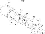
- Explanatory drawing which shows the example of a change of the switching mechanism of embodiment.
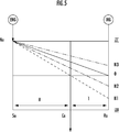
- Explanatory drawing which shows the action
- An automatic transmission 1 shown in FIG. 1 includes an input shaft 2 to which power of an internal combustion engine ENG that is an engine is transmitted, and an output gear that outputs power to left and right front wheels as drive wheels via a differential gear (not shown).
- the automatic transmission 1 includes a first drive gear shaft 4 that rotatably supports the drive gears G3a and G5a of the gear trains G3 and G5 of the odd-numbered shift stages in the gear ratio order, and an even number in the gear ratio order.
- a second drive gear shaft 5 that rotatably supports the drive gears G2a and G4a of the gear trains G2 and G4 of the second gear stage and a reverse shaft 6 that rotatably supports the reverse gear GR are provided.
- the automatic transmission 1 includes an idle drive gear Gia rotatably supported on the first drive gear shaft 4, a first idle driven gear Gib fixed to the reverse shaft 6 and meshed with the idle drive gear Gia, An idle gear train Gi composed of a second idle driven gear Gic fixed to the two drive gear shaft 5 is provided.
- the first drive gear shaft 4 is disposed on the same axis as the input shaft 2, and the second drive gear shaft 5 is disposed in parallel with the first drive gear shaft 4.
- the rotation of the input shaft 2 is releasably transmitted to the first drive gear shaft 4 via the first clutch C1.
- the rotation of the input shaft 2 is releasably transmitted to the idle drive gear Gia via the second clutch C2. That is, the rotation of the input shaft 2 is releasably transmitted to the second drive gear shaft 5 via the second clutch C2 and the idle gear train Gi.
- a planetary gear mechanism PG is disposed coaxially with the input shaft 2.
- the planetary gear mechanism PG is configured as a single pinion type including a sun gear Sa, a ring gear Ra, and a carrier Ca that pivotally supports a pinion Pa meshing with the sun gear Sa and the ring gear Ra so as to rotate and revolve.
- the three elements including the sun gear Sa, the carrier Ca, and the ring gear Ra of the planetary gear mechanism PG are arranged in the order corresponding to the gear ratio in the speed diagram shown in FIG.
- the first element is the sun gear Sa
- the second element is the carrier Ca
- the third element is the ring gear Ra.
- the sun gear Sa as the first element is fixed to the first drive gear shaft 4.
- the carrier Ca as the second element is coupled to the third speed drive gear G3a of the third speed gear train G3.
- the ring gear Ra as the third element is fixed to the transmission case 7 by the brake B1 so as to be releasable.
- the brake B1 is a two-way clutch that can be switched to either a state that allows forward rotation (rotation in the forward direction) and prevents reverse rotation (rotation in the reverse direction), or a state that prevents forward rotation and allows reverse rotation. It consists of The brake B1 is not limited to the two-way clutch, and may be constituted by other types such as a wet multi-plate brake, a hub brake, and a band brake.
- a hollow electric motor MG (motor / generator) is disposed outside the planetary gear mechanism PG in the radial direction.
- the planetary gear mechanism PG is disposed inside the hollow electric motor MG.
- the electric motor MG includes a stator MGa and a rotor MGb.
- the electric motor MG is controlled via the power drive unit PDU based on an instruction signal from the controller ECU.
- the controller ECU is configured to drive the electric motor MG by consuming the electric power of the secondary battery BATT. Then, the rotational force of the rotor MGb is suppressed to generate power, and the generated power is appropriately switched to a regenerative state in which the secondary battery BATT is charged via the power drive unit PDU.
- the automatic transmission 1 can be switched between a state where the rotor MGb and the sun gear Sa are connected, a state where the rotor MGb and the ring gear Rb are connected, and a state where the rotor MGb is disconnected from the sun gear Sa and the ring gear Ra.
- a switching mechanism 8 is provided.
- the reverse gear GR is rotatably supported on the reverse shaft 6.
- a second driven gear G2a and a first driven gear Go1 that meshes with the third speed driven gear G3a are rotatably supported on the output shaft 3a that supports the output member 3.
- a second driven gear Go2 that meshes with the fourth speed drive gear G4a and the fifth speed drive gear G5a is fixed to the output shaft 3a.
- the shaft length of the transmission can be shortened, and the FF (front wheel drive) system can be mounted on a vehicle.
- the first drive gear shaft 4 is composed of a synchromesh mechanism, and the fifth speed drive gear G5a and the first drive gear shaft 4 are connected in a state where the third speed drive gear G3a and the first drive gear shaft 4 are connected.
- a first meshing mechanism SM1 that can be switched to any one of the three-speed driving gear G3a and the fifth-speed driving gear G5a and the first driving gear shaft 4 in a disconnected state.
- the second drive gear shaft 5 is composed of a synchromesh mechanism, and the second speed drive gear G2a and the second drive gear shaft 5 are connected, and the fourth speed drive gear G5a and the second drive gear shaft 5 are connected.
- a second meshing mechanism SM2 that can be switched to any one of a state in which the connection between the state, the second speed drive gear G2a and the fourth speed drive gear G5a, and the second drive gear shaft 5 is disconnected.
- the output shaft 3a is provided with a third meshing mechanism SM3 that is configured by a synchromesh mechanism and can be switched between a state in which the first driven gear Go1 and the output shaft 3a are connected and a state in which the connection is cut off. It has been.
- the reverse shaft 6 includes a synchromesh mechanism, and is provided with a fourth meshing mechanism SM4 that can be switched between a state in which the reverse gear GR and the reverse shaft 6 are connected and a state in which the connection is cut off. Yes.
- the sun gear Sa of the planetary gear mechanism PG is formed in a cylindrical shape, and a first recess Sa1 is provided on the inner peripheral surface thereof.
- the ring gear Ra is connected to a connecting sleeve 81 arranged on the same axis as the planetary gear mechanism PG.
- the inner diameter of the connecting sleeve 81 is set to be the same as the inner diameter of the cylindrical sun gear Sa.
- a second recess 81 a is provided on the inner peripheral surface of the connection sleeve 81.
- a switching sleeve 82 connected to the rotor MGb of the electric motor MG is inserted.
- the switching sleeve 82 is provided with first and second through holes 83a and 83b that penetrate in the radial direction corresponding to the positions of the recesses Sa1 and 81a with a gap in the axial direction of the switching sleeve 82. Yes.
- a first protruding member 84a is inserted into the first through hole 83a, and a second protruding member 84b is inserted into the second through hole 83b.
- a rod 86 that can be moved forward and backward by a linear actuator 85 is inserted in the switching sleeve 82.
- the rod 86 has a diameter-expanded portion 87 having a first tapered surface 87a at one axial end and a second tapered surface 87b at the other axial end.
- the rod 86 is normally disposed such that the enlarged diameter portion 87 is located between the first projecting member 84a and the second projecting member 84b.
- Tapered surfaces facing the tapered surfaces 87a and 87b of the enlarged diameter portion 87 are formed at the inner ends of the protruding members 84a and 84b, respectively. Further, the protruding members 84a and 84b are urged radially inward by the urging force of the spring which is an elastic member, and are normally in a non-projecting state where they do not protrude from the through holes 83a and 83b (FIG. 2 ( a)).
- the linear actuator 85 causes the rods to be in a position where both the tapered surfaces 87a, 87b of the enlarged diameter portion 87 are not in contact with both the projecting members 84a, 84b. If 86 is positioned, the planetary gear mechanism PG and the rotor MGb are disconnected.
- the automatic transmission 1 includes a rotation speed detection mechanism (not shown) that detects the rotation speed of the rotor MGb, and the rotation speed of the rotor MGb detected by the rotation speed detection mechanism is transmitted to the controller ECU.
- the controller ECU determines that the electric motor MG is out of order and switches the switching mechanism 8 to the planetary gear mechanism PG.
- the state is switched to the state where the connection with the rotor MGb is broken. Thereby, it is possible to travel in the internal combustion engine ENG without being affected by the failed electric motor MG.
- the failure detection mechanism of the present invention is constituted by the rotation speed detection mechanism and the controller ECU.
- the failure detection mechanism may use another configuration as long as it can detect a failure of the electric motor MG.
- a temperature measurement mechanism that measures the temperature of the electric motor MG is used, and when the temperature measured by the controller ECU is an abnormal temperature, the switching mechanism 8 is replaced with the planetary gear mechanism.
- the PG and the rotor MGb may be switched to a disconnected state.
- the switching mechanism 8 is not limited to that of the present embodiment shown in FIG. 2, and other configurations may be used as long as switching is possible.
- the first projecting member 84a projects, the second projecting member 84b projects, and the first and second projecting members 84a and 84b. It may be configured to be switchable to a state in which does not protrude.
- FIGS. 2 An example of the switching mechanism 8 using this cam mechanism will be described with reference to FIGS. 2 that are the same as those of the switching mechanism 8 shown in FIG.
- the switching mechanism 8 using the cam mechanism shown in FIG. 3 and FIG. 4 includes a cylindrical groove cam 88 that slidably inserts the tip of a rod 86 that can be advanced and retracted by a linear actuator 85.
- the cylindrical groove cam 88 is formed with a cam groove 88a whose peripheral surface is cut obliquely.
- a protrusion 86a is provided at the tip of the rod 86 so as to protrude from the cam groove 88a.
- a cam shaft 89 extends from the end of the cylindrical groove cam 88 on the internal combustion engine ENG side.
- the camshaft 89 is inserted into the switching sleeve 82 so as to be rotatable and prevented from moving in the axial direction.
- a first plate cam 89a is fixed to the cam shaft 89 at a position corresponding to the first protruding member 84a, and a second plate cam 89b is fixed at a position corresponding to the second protruding member 84b.
- both the protruding members 84a and 84b are Is not engaged with both concave portions Sa1, 81a.
- the switching mechanism 8 is connected to the electric motor MG and the sun gear Sa, and the electric motor MG is engaged by engaging the first clutch C1.
- the internal combustion engine ENG To start the internal combustion engine ENG.
- the third meshing mechanism SM3 is brought into a state where the first driven gear Go1 and the output shaft 3a are connected, and the planetary gear mechanism PG is driven by the brake B1.
- the ring gear Ra is fixed to the transmission case 7, and the first clutch C1 is engaged.
- the driving force of the internal combustion engine ENG is input to the sun gear Sa of the planetary gear mechanism PG via the input shaft 2, the first clutch C1, and the first driving gear shaft 4, and the rotational speed of the internal combustion engine ENG input to the input shaft 2 Is reduced to 1 / (g + 1), where g is the gear ratio of the planetary gear mechanism PG (number of teeth of the ring gear Ra / number of teeth of the sun gear Sa), and is transmitted to the third speed drive gear G3a via the carrier Ca.
- the gear ratio (the number of teeth of the third speed driving gear G3a / the number of teeth of the first driven gear Go1) of the third speed gear train G3 configured by the third speed driving gear G3a and the first driven gear Go1 is defined as 1 / i ( The gear is shifted to g + 1) and output from the output member 3, and the first gear is established.
- the switching mechanism 8 In the first gear, when the electric motor MG is not used, the switching mechanism 8 is in a state of disconnecting the sun gear Sa and the ring gear Ra. Thereby, the rotation loss by the inertia (inertia) of the electric motor MG can be prevented.
- the switching mechanism 8 may be in a state where the connection between the sun gear Sa and the ring gear Ra is disconnected.
- regeneration can be performed by connecting the electric motor MG to the sun gear Sa by the switching mechanism 8 and applying a brake with the electric motor MG.
- the electric motor MG is driven to assist driving that assists the driving force of the internal combustion engine ENG, or EV that travels only by the driving force of the electric motor MG. (Electric Vehicle) can run.
- the internal combustion engine ENG can be started by engaging the first clutch C1.
- the regenerative operation can be performed by releasing the fixation of the ring gear Ra by the brake B1 and connecting the electric motor MG to the ring gear Ra by the switching mechanism 8.
- the carrier Ca connected to the output member 3 has a much larger inertia than the ring gear Ra to which the electric motor MG is connected. .
- the rotational speed of the carrier Ca is approximately the rotational speed Ne of the sun gear Sa to which the power of the internal combustion engine ENG is transmitted.
- the ring gear Ra rotates in the reverse direction (rotation in the reverse direction side, N1 in FIG. 3).
- the electric power is generated by braking the electric motor MG so that the rotational speed of the ring gear Ra is changed from N1 to N2, and the regenerative operation is performed, so that a driving force on the forward rotation side (forward direction side) is generated in the carrier Ca (FIG. 3 dash-dot line).
- the forward driving force is generated by the electric motor MG
- the driving force of the internal combustion engine ENG and the driving force of the electric motor MG are combined by the carrier Ca and output from the output member 3. Therefore, it becomes easy to produce a large driving force, and the followability (drivability) to the driver's operation can be improved.
- the second meshing mechanism SM2 is driven by the second speed drive gear G2a and the second drive. A state in which the gear shaft 5 is coupled or a pre-shift state in which this state is approached is set.
- the gear ratio g of the planetary gear mechanism PG and the gear ratio i of the third speed gear train G3 are set to relatively small values with an emphasis on fuel consumption. Then, when performing the assist travel, the controller ECU connects the rotor MGb of the electric motor MG to the sun gear Sa and assists the travel based on vehicle information such as the depression amount of the accelerator pedal. When starting with an emphasis on driving force (torque), the rotor MGb of the electric motor MG is connected to the ring gear Ra for assist running.
- the second meshing mechanism SM2 When the second speed is established using the driving force of the internal combustion engine ENG, the second meshing mechanism SM2 is brought into a state in which the second speed driving gear G2a and the second driving gear shaft 5 are connected, and the third meshing mechanism SM3. Is connected to the first driven gear Go1 and the output shaft 3a, and the second clutch C2 is engaged.
- the first meshing mechanism SM1 is brought into a state where the third speed drive gear G3a and the first drive gear shaft 4 are connected or in a preshift state approaching this state.
- the controller ECU When the vehicle is in a decelerating state and the charging rate SOC of the secondary battery BATT is less than a predetermined value, the controller ECU performs deceleration regeneration. In the second speed reduction regeneration, the brake B1 is engaged, and the carrier Ca that rotates together with the third-speed drive gear G3a meshing with the first driven gear Go1 is generated by the electric motor MG connected to the sun gear Sa by the switching mechanism 8. Apply the brakes to regenerate.
- the first meshing mechanism SM1 is connected to the third speed drive gear G3a and the first drive gear shaft 4, and the three elements of the planetary gear mechanism PG are changed.
- the electric motor MG may be connected to the sun gear Sa or the ring gear Ra by the switching mechanism 8, and braking may be performed by the electric motor MG to perform deceleration regeneration.
- the first meshing mechanism SM1 is connected to the third speed drive gear G3a and the first drive gear shaft 4, the planetary gear mechanism PG is locked, and the switching mechanism 8
- the electric motor MG is connected to the sun gear Sa or the ring gear Ra, and the driving force of the electric motor MG is transmitted to the output member 3 via the third speed gear train G3.
- the first clutch C1 When the third speed is established using the driving force of the internal combustion engine ENG, the first clutch C1 is set with the first meshing mechanism SM1 connected to the third speed driving gear G3a and the first driving gear shaft 4. Engage.
- the driving force of the internal combustion engine ENG is transmitted to the output member 3 via the input shaft 2, the first clutch C1, the first driving gear shaft 4, the first meshing mechanism SM1, and the third gear train G3. Is output at a rotation speed of / i.
- the first meshing mechanism SM1 is in a state where the third speed driving gear G3a and the first driving gear shaft 4 are connected, so that the sun gear Sa of the planetary gear mechanism PG and the carrier Ca are rotated in the same rotation. Become. Accordingly, each element of the planetary gear mechanism PG enters a locked state in which relative rotation is impossible.
- the sun gear Sa or the ring gear Ra is braked by the switching mechanism 8 by the electric motor MG, deceleration regeneration is performed, and the driving force is applied to the sun gear Sa or the ring gear Ra by the electric motor MG. If it is transmitted, assist traveling can be performed.
- the controller ECU sets the second meshing mechanism SM2 to a state in which the second speed drive gear G2a and the second drive gear shaft 5 are connected to each other or a preshift state in which the second engagement mechanism SM2 is close to this state.
- the second meshing mechanism SM2 is brought into a state in which the fourth speed drive gear G4a and the second drive gear shaft 5 are connected or in a preshift state in which this state is brought close to this state.
- the gear stage can be switched by simply engaging the second clutch C2 and disengaging the first clutch C1, and the shift can be performed smoothly.
- the second meshing mechanism SM2 When establishing the fourth speed stage using the driving force of the internal combustion engine ENG, the second meshing mechanism SM2 is brought into a state where the fourth speed driving gear G4a and the second driving gear shaft 5 are connected, and the second clutch C2 is engaged. Engage.
- the first meshing mechanism SM1 When the controller ECU is predicting a downshift from the vehicle information during traveling at the fourth speed, the first meshing mechanism SM1 is connected to the third speed driving gear G3a and the first driving gear shaft 4, or The pre-shift state is brought close to this state, and the third meshing mechanism SM3 is in a state where the first driven gear Go1 and the output shaft 3a are connected.
- the first meshing mechanism SM1 is connected to the state in which the fifth speed drive gear G5a and the first drive gear shaft 4 are connected or close to this state. Set to pre-shift state.
- the downshift or the upshift can be performed simply by engaging the first clutch C1 and releasing the second clutch C2, and the shift can be performed smoothly.
- the first meshing mechanism SM1 When performing deceleration regeneration or assist traveling during traveling at the fourth speed, when the controller ECU predicts a downshift, the first meshing mechanism SM1 is connected to the third speed driving gear G3a and the first driving gear shaft 4. The connected state is set, and the third meshing mechanism SM3 is set in a state where the first driven gear Go1 and the output shaft 3a are connected.
- the switching mechanism 8 may be in a state where the rotor MGb is connected to the sun gear Sa or the ring gear Ra.
- the electric motor MG When performing the assist travel, the electric motor MG is driven, and the driving force of the electric motor MG is transmitted to the output member 3 via the first drive gear shaft 4 and the third speed gear train.
- the first meshing mechanism SM1 is connected to the fifth speed drive gear G5a and the first drive gear shaft 4, and the switching mechanism 8 is connected to the rotor MGb and the sun gear Sa of the electric motor MG. Are connected.
- the first meshing mechanism SM1 When establishing the fifth speed using the driving force of the internal combustion engine ENG, the first meshing mechanism SM1 is in a state where the fifth speed driving gear G5a and the first driving gear shaft 4 are connected.
- the rotor MGb of the electric motor MG is connected to the sun gear Sa by the switching mechanism 8.
- the first clutch C1 is released. Note that the internal combustion engine ENG can also be started by gradually engaging the first clutch C1 during EV traveling at the fifth gear.
- the controller ECU When the controller ECU predicts a downshift from the vehicle information to the fourth speed while traveling at the fifth speed, the controller ECU couples the second meshing mechanism SM2 with the fourth speed drive gear G4a and the second drive gear shaft 5. Or a pre-shift state approaching this state. Thereby, the downshift to the 4th gear stage can be performed smoothly.
- the controller ECU does not predict a downshift from the vehicle information to the fourth speed stage while traveling at the fifth speed stage, and the charge rate SOC of the secondary battery BATT is less than a predetermined value.
- the second meshing mechanism SM2 is in a state where the second speed drive gear G2a and the second drive gear shaft 5 are connected, and the switching mechanism 8 is connected between the rotor MGb and the ring gear Ra.
- the ring gear Ra is rotated at a predetermined rotation speed by the electric motor MG.
- the driving force of the internal combustion engine ENG is distributed to the sun gear Sa and the ring gear Ra connected to the output member 3 by generating electric power with the electric motor MG and performing regeneration.
- the distance between the sun gear Sa and the carrier Ca is wider than the distance between the carrier Ca and the ring gear Ra, and therefore the driving force of the internal combustion engine ENG transmitted to the carrier Ca. Is not easily transmitted to the sun gear Sa connected to the output member 3. For this reason, the fuel consumption in the fifth gear can be improved.
- the controller ECU does not predict a downshift to the fourth speed from the vehicle information, and the charge rate SOC of the secondary battery BATT is equal to or greater than a predetermined value.
- the first clutch C1 can be engaged to start the internal combustion engine ENG and switch to the traveling state using only the driving force of the internal combustion engine ENG.
- the brake B1 is engaged, the rotation speed of the ring gear Ra is set to 0, and the second meshing mechanism SM2 is connected to the second speed driving gear G2a and the second driving gear shaft 5. It is assumed that Then, the second clutch C2 is engaged, and the driving force of the internal combustion engine ENG is transmitted to the carrier Ca, so that the assist traveling can be performed in which the driving force of the electric motor MG is assisted by the driving force of the internal combustion engine ENG.
- the third meshing mechanism SM3 is connected to the second speed drive gear G2b and the output shaft 3a, and the fourth meshing mechanism SM4 is connected to the reverse gear GR.
- the second clutch C2 is engaged with the reverse shaft 6 connected.
- the rotation speed of the input shaft 2 is [number of teeth of the idle drive gear Gia / number of teeth of the first idle driven gear Gib] ⁇ [number of teeth of the reverse gear GR / number of teeth of the first driven gear Go1].
- the speed is changed to a negative rotation (rotation in the reverse direction) and output from the output member 3.
- the first meshing mechanism SM1 When performing deceleration regeneration and assist travel in the reverse gear, the first meshing mechanism SM1 is connected to the third speed drive gear G3a and the first drive gear shaft 4, and the planetary gear mechanism PG is locked. Then, if a forward driving force is generated in the rotating rotor MGb (if the brake is applied), deceleration regeneration is performed, and if reverse driving force is generated, assist traveling is performed.
- any one of the state in which the electric motor MG is connected to the sun gear Sa, the state in which the electric motor MG is connected to the ring gear Ra, and the state in which the electric motor MG is disconnected from the planetary gear mechanism PG by the switching mechanism 8. Can be switched to any state.
- the motor MG can be connected to the ring gear Ra by the switching mechanism 8 and the vehicle can be started while performing regeneration.
- a start stage having a lower rotational speed than the normal first speed stage shown by the solid line in FIG. 3 can be established, and a more appropriate start can be made according to the vehicle state. Since the step can be selected, it is possible to improve the followability (drivability) to the driver's operation and improve the fuel efficiency.
Landscapes
- Engineering & Computer Science (AREA)
- Mechanical Engineering (AREA)
- Transportation (AREA)
- General Engineering & Computer Science (AREA)
- Combustion & Propulsion (AREA)
- Chemical & Material Sciences (AREA)
- Power Engineering (AREA)
- Life Sciences & Earth Sciences (AREA)
- Sustainable Energy (AREA)
- Sustainable Development (AREA)
- Automation & Control Theory (AREA)
- Electric Propulsion And Braking For Vehicles (AREA)
- Structure Of Transmissions (AREA)
- Hybrid Electric Vehicles (AREA)
- Gear-Shifting Mechanisms (AREA)
- Retarders (AREA)
- Mechanical Operated Clutches (AREA)
- Transmission Devices (AREA)
Abstract
Description
本発明においては、切換機構を、プラネタリギヤ機構の第1要素又は第3要素の何れの連結も断つ状態に切換自在に構成されることが好ましい。かかる構成によれば、電動機を完全に切り離すことができる。これにより、電動機を用いていない場合に、全ての変速段において、電動機を切り離すことができ、電動機のイナーシャ(慣性)による燃費の低下を防止することができる。
Claims (7)
- 内燃機関と電動機とを備えるハイブリッド車両用の自動変速機であって、前記内燃機関の動力が伝達される入力軸の回転を複数のギヤ列を介して複数段に変速して出力部材から出力するものにおいて、
変速比順位で奇数番目の変速段を確立する各ギヤ列の駆動ギヤを軸支する第1駆動ギヤ軸と、
変速比順位で偶数番目の変速段を確立する各ギヤ列の駆動ギヤを軸支する第2駆動ギヤ軸と、
前記入力軸と前記第1駆動ギヤ軸とを解除自在に連結する第1クラッチと、
前記入力軸と前記第2駆動ギヤ軸とを解除自在に連結する第2クラッチと、
変速比順位で奇数番目の変速段を確立する各ギヤ列の駆動ギヤを第1駆動ギヤ軸に選択的に連結する第1噛合機構と、
変速比順位で偶数番目の変速段を確立する各ギヤ列の駆動ギヤを第2駆動ギヤ軸に選択的に連結する第2噛合機構と、
サンギヤとキャリアとリングギヤとの3つの要素を備えるプラネタリギヤ機構と、
前記プラネタリギヤ機構の前記サンギヤ、キャリア、リングギヤからなる3つの要素を、速度線図におけるギヤ比に対応する間隔での並び順に夫々第1要素、第2要素、第3要素として、
前記第3要素を変速機ケースに解除自在に固定するブレーキと、
前記電動機のロータを前記プラネタリギヤ機構の第1要素に接続する状態、前記電動機のロータを前記プラネタリギヤ機構の第3要素に接続する状態の何れかの状態に切換自在な切換機構とを備え、
前記第1要素と前記第1駆動ギヤ軸とが連結され、
前記第2要素と前記第1駆動ギヤ軸に軸支される何れか1つの駆動ギヤとが連結されることを特徴とする自動変速機。 - 請求項1記載の自動変速機において、
前記切換機構は、前記プラネタリギヤ機構の第1要素又は第3要素の何れの連結も断つ状態に切換自在に構成されることを特徴とする自動変速機。 - 請求項2記載の自動変速機において、
前記電動機の故障を検知する故障検知機構を備え、
該故障検知機構が前記電動機の故障を検知した場合には、前記切換機構は前記プラネタリギヤ機構の第1要素又は第3要素の何れの連結も断つ状態に切り換えられることを特徴とする自動変速機。 - 請求項1から請求項3の何れか1項に記載の自動変速機において、
前記切換機構は、切換スリーブと、直動アクチュエータにより該切換スリーブ内を進退自在なロッドとを備え、
前記切換スリーブと前記電動機のロータとが連結され、
前記切換スリーブには、径方向に貫通する第1と第2の2つの貫通孔が互いに切換スリーブの軸方向に間隔を存して設けられ、該第1貫通孔には第1突出部材が内挿され、該第2貫通孔には第2突出部材が内挿され、
該2つの貫通孔内には、該突出部材を径方向内方へ付勢する弾性部材が夫々配置され、
前記ロッドには、次第に径方向外方へ拡径する拡径部を設けることにより第1と第2の2つのテーパ面が形成され、
前記ロッドが前記直動アクチュエータにより前進又は後退され前記第1テーパ面が前記第1突出部材に接触することにより、前記第1突出部材が弾性部材の付勢力に抗して前記切換スリーブから径方向外方に突出し、前記第1突出部材が前記プラネタリギヤ機構の第1要素に連結された第1凹部に係合して、前記切換機構が前記電動機のロータを前記第1要素に接続する状態となり、
前記ロッドが前記直動アクチュエータにより後退又は前進され前記第2テーパ面が前記第2突出部材に接触することにより、前記第2突出部材が弾性部材の付勢力に抗して前記切換スリーブから径方向外方に突出し、前記第2突出部材が前記プラネタリギヤ機構の第3要素に連結された第2凹部に係合して、前記切換機構が前記電動機のロータを前記第3要素に接続する状態となることを特徴とする自動変速機。 - 請求項1から請求項3の何れか1項に記載の自動変速機において、
前記切換機構は、切換スリーブと、直動アクチュエータにより軸方向に進退自在なロッドと、該ロッドの進退運動を回転運動に切り換える円筒溝カムと、該円筒溝カムに連結され第1と第2の2つの板カムが固定されるカム軸とを備え、
前記切換スリーブと前記電動機のロータとが連結され、
前記切換スリーブには、径方向に貫通する第1と第2の2つの貫通孔が互いに軸方向に間隔を存して設けられ、該第1貫通孔には第1突出部材が内挿され、該第2貫通孔には第2突出部材が内挿され、
該2つの貫通孔内には、該突出部材を径方向内方へ付勢する弾性部材が夫々配置され、
前記円筒溝カムは、前記ロッドの進退運動により、前記第1板カムが第1突出部材を弾性部材の付勢力に抗して突き出させ、前記第1突出部材が前記プラネタリギヤ機構の第1要素に連結された第1凹部に係合する第1位相、又は前記第2板カムが第2突出部材を弾性部材の付勢力に抗して突き出させ、前記第2突出部材が前記プラネタリギヤ機構の第3要素に連結された第2凹部に係合する第2位相に切換自在に構成されることを特徴とする自動変速機。 - 請求項1から請求項5の何れか1項に記載の自動変速機において、
二次電池の充電率が所定値未満であり、内燃機関の駆動力を用いて車両を発進させる場合には、
前記切換機構は前記電動機のロータを前記プラネタリギヤ機構の第3要素に接続する状態に切り換えられ、
前記第1クラッチを係合して、前記内燃機関の駆動力を前記プラネタリギヤ機構の第1要素に伝達させると共に、逆転する前記第3要素の回転を前記電動機で抑制して、前記第2要素及びこれに連結される駆動ギヤを備えるギヤ列を介して出力部材から動力を出力することを特徴とする自動変速機。 - 請求項1から請求項6の何れか1項に記載の自動変速機において、
車両速度が所定速度未満の低速走行状態であり、二次電池の充電率が所定値以上であって且つ外気温が所定温度以下の低温環境である場合には、
前記切換機構は前記電動機のロータを前記プラネタリギヤ機構の第1要素に接続する状態に切り換えられることを特徴とする自動変速機。
Priority Applications (3)
| Application Number | Priority Date | Filing Date | Title |
|---|---|---|---|
| CN201080022814.5A CN102448757B (zh) | 2009-06-10 | 2010-03-25 | 混合动力车用的自动变速器 |
| DE112010002436T DE112010002436T5 (de) | 2009-06-10 | 2010-03-25 | Automatikgetriebe für ein Hybridfahrzeug |
| US13/318,755 US8517876B2 (en) | 2009-06-10 | 2010-03-25 | Automatic transmission for hybrid vehicle |
Applications Claiming Priority (2)
| Application Number | Priority Date | Filing Date | Title |
|---|---|---|---|
| JP2009-138930 | 2009-06-10 | ||
| JP2009138930A JP4926209B2 (ja) | 2009-06-10 | 2009-06-10 | ハイブリッド車両用の自動変速機 |
Publications (1)
| Publication Number | Publication Date |
|---|---|
| WO2010143463A1 true WO2010143463A1 (ja) | 2010-12-16 |
Family
ID=43308723
Family Applications (1)
| Application Number | Title | Priority Date | Filing Date |
|---|---|---|---|
| PCT/JP2010/055220 Ceased WO2010143463A1 (ja) | 2009-06-10 | 2010-03-25 | ハイブリッド車両用の自動変速機 |
Country Status (5)
| Country | Link |
|---|---|
| US (1) | US8517876B2 (ja) |
| JP (1) | JP4926209B2 (ja) |
| CN (1) | CN102448757B (ja) |
| DE (1) | DE112010002436T5 (ja) |
| WO (1) | WO2010143463A1 (ja) |
Cited By (5)
| Publication number | Priority date | Publication date | Assignee | Title |
|---|---|---|---|---|
| EP2723595A1 (en) * | 2011-06-27 | 2014-04-30 | Scania CV AB | Powertrain for a vehicle and method for controlling a powertrain |
| CN104220315A (zh) * | 2012-04-04 | 2014-12-17 | 丰田自动车株式会社 | 车辆用驱动装置 |
| CN104364109A (zh) * | 2012-05-31 | 2015-02-18 | 罗伯特·博世有限公司 | 双速传动装置和电动车辆 |
| US20150167806A1 (en) * | 2013-12-18 | 2015-06-18 | Hyundai Motor Company | Power transmission apparatus for vehicle |
| US9695932B2 (en) | 2013-12-18 | 2017-07-04 | Hyundai Motor Company | Power transmission apparatus for vehicle |
Families Citing this family (52)
| Publication number | Priority date | Publication date | Assignee | Title |
|---|---|---|---|---|
| US8622862B2 (en) * | 2009-03-24 | 2014-01-07 | Honda Motor Co., Ltd. | Power transmitting device |
| US20130103241A1 (en) * | 2010-06-28 | 2013-04-25 | Honda Motor Co., Ltd | Vehicle control unit and control method |
| DE102011005562A1 (de) * | 2011-03-15 | 2012-09-20 | Zf Friedrichshafen Ag | Schaltgetriebe eines Hybridantriebs für ein Kraftfahrzeug |
| KR101282721B1 (ko) | 2011-04-01 | 2013-07-04 | 한국과학기술원 | 복수개의 입력축을 구비하는 변속기어열 및 이를 이용하는 변속장치 |
| SE536049C2 (sv) * | 2011-06-27 | 2013-04-16 | Scania Cv Ab | Regenerativ bromsanordning för ett fordon och förfarande för regenerativ bromsning av ett fordon |
| JP5812182B2 (ja) * | 2012-02-28 | 2015-11-11 | トヨタ自動車株式会社 | ハイブリッド車両の駆動装置 |
| DE102012016988A1 (de) | 2012-08-25 | 2014-05-15 | Volkswagen Aktiengesellschaft | Hybridantriebsstrang für ein Kraftfahrzeug, Hybridfahrzeug und dessen Verwendung |
| JP5660116B2 (ja) * | 2012-12-25 | 2015-01-28 | トヨタ自動車株式会社 | ハイブリッド車両の制御装置 |
| DE102013200158A1 (de) * | 2013-01-09 | 2014-07-10 | Zf Friedrichshafen Ag | Hybridantrieb für ein Kraftfahrzeug |
| CN104918813B (zh) * | 2013-01-28 | 2017-09-26 | 丰田自动车株式会社 | 混合动力车辆 |
| JP5698288B2 (ja) * | 2013-03-07 | 2015-04-08 | 本田技研工業株式会社 | 自動変速機 |
| JP2014201132A (ja) * | 2013-04-02 | 2014-10-27 | トヨタ自動車株式会社 | 車両の制御装置 |
| JP2015033922A (ja) * | 2013-08-09 | 2015-02-19 | いすゞ自動車株式会社 | ハイブリッドシステム、ハイブリッド車両、及びハイブリッドシステムの制御方法 |
| DE102013221461A1 (de) * | 2013-10-23 | 2015-04-23 | Zf Friedrichshafen Ag | Hybridantrieb eines Kraftfahrzeugs |
| KR101543086B1 (ko) * | 2013-10-29 | 2015-08-07 | 현대자동차주식회사 | 차량의 하이브리드 파워트레인 |
| DE102013223462A1 (de) * | 2013-11-18 | 2015-05-21 | Zf Friedrichshafen Ag | Kraftfahrzeuggetriebe für einen Antriebsstrang eines Hybridfahrzeuges, sowie Antriebsstrang eines Hybridfahrzeuges |
| KR101550987B1 (ko) | 2013-11-25 | 2015-09-07 | 현대자동차주식회사 | 차량의 하이브리드 변속기 |
| KR101551004B1 (ko) | 2013-12-13 | 2015-09-18 | 현대자동차주식회사 | 차량의 하이브리드 변속기 |
| CA2933843A1 (en) | 2013-12-16 | 2015-06-25 | Honda Motor Co., Ltd. | Driving system |
| KR101566738B1 (ko) | 2013-12-18 | 2015-11-06 | 현대자동차 주식회사 | 차량의 변속장치 |
| KR101575316B1 (ko) * | 2013-12-18 | 2015-12-07 | 현대자동차 주식회사 | 차량의 변속장치 |
| KR101575321B1 (ko) * | 2013-12-18 | 2015-12-07 | 현대자동차 주식회사 | 차량의 변속장치 |
| KR20150071608A (ko) | 2013-12-18 | 2015-06-26 | 현대자동차주식회사 | 하이브리드 전기자동차의 변속장치 |
| KR20150071604A (ko) | 2013-12-18 | 2015-06-26 | 현대자동차주식회사 | 차량의 변속장치 |
| KR101518948B1 (ko) * | 2013-12-18 | 2015-05-12 | 현대자동차 주식회사 | 차량의 변속장치 |
| KR101628147B1 (ko) * | 2013-12-31 | 2016-06-08 | 현대자동차 주식회사 | 차량용 변속장치 |
| JP6172674B2 (ja) * | 2014-02-07 | 2017-08-02 | 本田技研工業株式会社 | 車両用動力伝達装置 |
| US9260108B2 (en) * | 2014-03-11 | 2016-02-16 | GM Global Technology Operations LLC | Hybrid powertrain and method for controlling the same |
| KR101519295B1 (ko) | 2014-05-09 | 2015-05-12 | 현대자동차주식회사 | 하이브리드 차량용 파워트레인 |
| KR101543164B1 (ko) | 2014-05-12 | 2015-08-10 | 현대자동차주식회사 | 하이브리드 차량용 파워트레인 |
| KR101637279B1 (ko) | 2014-09-23 | 2016-07-21 | 현대자동차 주식회사 | 차량의 변속장치 |
| EP3031648B1 (en) * | 2014-12-09 | 2018-02-07 | AVL List GmbH | Multi-speed transmission and method for operating the same |
| KR20160073234A (ko) | 2014-12-16 | 2016-06-24 | 현대자동차주식회사 | 하이브리드 차량용 구동장치 |
| KR101646464B1 (ko) * | 2015-05-13 | 2016-08-08 | 현대자동차주식회사 | 하이브리드 차량용 파워트레인 |
| KR101755794B1 (ko) * | 2015-06-17 | 2017-07-10 | 현대자동차주식회사 | 차량의 하이브리드 변속기 |
| EP3315822B1 (en) * | 2015-06-25 | 2021-01-13 | Nissan Motor Co., Ltd. | Gear-shift control device for hybrid vehicle |
| KR101724934B1 (ko) * | 2015-10-26 | 2017-04-10 | 현대자동차주식회사 | 차량용 변속기 |
| KR101619437B1 (ko) | 2015-12-30 | 2016-05-18 | 현대자동차주식회사 | 차량의 변속장치 |
| JP6326438B2 (ja) * | 2016-02-18 | 2018-05-16 | 本田技研工業株式会社 | 変速機 |
| SE539726C2 (en) * | 2016-03-17 | 2017-11-14 | Scania Cv Ab | Shift control arrangement with interlock in a vehicle gearbox |
| FR3052730B1 (fr) * | 2016-06-15 | 2018-07-13 | Alstom Transp Tech | Dispositif de traction pour un vehicule, notamment pour un vehicule ferroviaire, a securite amelioree |
| KR101875643B1 (ko) * | 2016-09-07 | 2018-07-06 | 현대자동차 주식회사 | 하이브리드 전기자동차의 동력전달장치 |
| KR101916073B1 (ko) * | 2016-10-21 | 2018-11-07 | 현대자동차 주식회사 | 하이브리드 전기자동차의 동력전달장치 |
| KR102451883B1 (ko) * | 2017-10-19 | 2022-10-06 | 현대자동차 주식회사 | 차량용 변속장치 |
| KR102451888B1 (ko) * | 2017-10-19 | 2022-10-06 | 현대자동차 주식회사 | 차량용 변속장치 |
| KR102394572B1 (ko) * | 2017-11-01 | 2022-05-06 | 현대자동차 주식회사 | 차량용 변속장치 |
| JP6830053B2 (ja) * | 2017-12-05 | 2021-02-17 | 株式会社豊田中央研究所 | シリーズハイブリッド自動車 |
| CN108843787B (zh) * | 2018-09-06 | 2019-12-24 | 湖南农业大学 | 一种用于履带运输车的变速传动装置 |
| KR102588325B1 (ko) * | 2018-12-27 | 2023-10-11 | 현대트랜시스 주식회사 | 전기차 파워트레인 및 그 제어방법 |
| CZ309458B6 (cs) * | 2019-01-14 | 2023-02-01 | ŠKODA AUTO a.s. | Hybridní převodovka osobního automobilu |
| CN114407639B (zh) * | 2022-03-11 | 2022-08-19 | 深圳市悦成汽车技术有限公司 | 一种混动汽车的多模式变速箱总成 |
| CN115027260B (zh) * | 2022-04-26 | 2025-08-26 | 浙江极氪智能科技有限公司 | 一种驱动脱开机构和汽车 |
Citations (3)
| Publication number | Priority date | Publication date | Assignee | Title |
|---|---|---|---|---|
| JP2005329813A (ja) * | 2004-05-20 | 2005-12-02 | Hino Motors Ltd | デュアルクラッチ式変速機を搭載したハイブリッド車両 |
| JP2007246057A (ja) * | 2006-03-20 | 2007-09-27 | Honda Motor Co Ltd | ハイブリッド車両の駆動装置 |
| JP2009083520A (ja) * | 2007-09-27 | 2009-04-23 | Toyota Motor Corp | 車両用駆動装置 |
Family Cites Families (10)
| Publication number | Priority date | Publication date | Assignee | Title |
|---|---|---|---|---|
| JP3647399B2 (ja) * | 2000-09-14 | 2005-05-11 | 株式会社日立製作所 | 車両用動力伝達システムおよびそれを搭載した自動車 |
| WO2006137602A1 (ja) * | 2005-06-24 | 2006-12-28 | Toyota Jidosha Kabushiki Kaisha | 車両用駆動装置 |
| US7462121B2 (en) * | 2006-05-12 | 2008-12-09 | Ford Global Technologies, Llc | Hybrid electric vehicle powertrain with four-wheel drive characteristics |
| JP4229156B2 (ja) * | 2006-09-06 | 2009-02-25 | トヨタ自動車株式会社 | 動力出力装置およびハイブリッド自動車 |
| US7575529B2 (en) * | 2006-09-13 | 2009-08-18 | Gm Global Technology Operations, Inc. | Hybrid electrically variable transmission with geared reverse mode using single motor/generator |
| JP2008302800A (ja) * | 2007-06-07 | 2008-12-18 | Mazda Motor Corp | 車両用駆動装置 |
| AR075776A1 (es) * | 2009-03-03 | 2011-04-27 | Honda Motor Co Ltd | Aparato de transmision de potencia para vehiculo hibrido |
| US8241161B2 (en) * | 2009-06-12 | 2012-08-14 | GM Global Technology Operations LLC | Hybrid module for interconnecting an engine and a transmission |
| DE102010006043A1 (de) * | 2010-01-28 | 2011-08-18 | Dr. Ing. h.c. F. Porsche Aktiengesellschaft, 70435 | Hybridantriebsstrang |
| CN102803038B (zh) * | 2010-03-31 | 2015-05-20 | 本田技研工业株式会社 | 混合动力车辆 |
-
2009
- 2009-06-10 JP JP2009138930A patent/JP4926209B2/ja not_active Expired - Fee Related
-
2010
- 2010-03-25 WO PCT/JP2010/055220 patent/WO2010143463A1/ja not_active Ceased
- 2010-03-25 DE DE112010002436T patent/DE112010002436T5/de not_active Withdrawn
- 2010-03-25 US US13/318,755 patent/US8517876B2/en not_active Expired - Fee Related
- 2010-03-25 CN CN201080022814.5A patent/CN102448757B/zh not_active Expired - Fee Related
Patent Citations (3)
| Publication number | Priority date | Publication date | Assignee | Title |
|---|---|---|---|---|
| JP2005329813A (ja) * | 2004-05-20 | 2005-12-02 | Hino Motors Ltd | デュアルクラッチ式変速機を搭載したハイブリッド車両 |
| JP2007246057A (ja) * | 2006-03-20 | 2007-09-27 | Honda Motor Co Ltd | ハイブリッド車両の駆動装置 |
| JP2009083520A (ja) * | 2007-09-27 | 2009-04-23 | Toyota Motor Corp | 車両用駆動装置 |
Cited By (7)
| Publication number | Priority date | Publication date | Assignee | Title |
|---|---|---|---|---|
| EP2723595A1 (en) * | 2011-06-27 | 2014-04-30 | Scania CV AB | Powertrain for a vehicle and method for controlling a powertrain |
| CN104220315A (zh) * | 2012-04-04 | 2014-12-17 | 丰田自动车株式会社 | 车辆用驱动装置 |
| CN104220315B (zh) * | 2012-04-04 | 2016-12-14 | 丰田自动车株式会社 | 车辆用驱动装置 |
| CN104364109A (zh) * | 2012-05-31 | 2015-02-18 | 罗伯特·博世有限公司 | 双速传动装置和电动车辆 |
| US20150167806A1 (en) * | 2013-12-18 | 2015-06-18 | Hyundai Motor Company | Power transmission apparatus for vehicle |
| US9695932B2 (en) | 2013-12-18 | 2017-07-04 | Hyundai Motor Company | Power transmission apparatus for vehicle |
| US9719592B2 (en) * | 2013-12-18 | 2017-08-01 | Hyundai Motor Company | Power transmission apparatus for vehicle |
Also Published As
| Publication number | Publication date |
|---|---|
| US20120115677A1 (en) | 2012-05-10 |
| JP2010285012A (ja) | 2010-12-24 |
| DE112010002436T5 (de) | 2012-10-25 |
| JP4926209B2 (ja) | 2012-05-09 |
| US8517876B2 (en) | 2013-08-27 |
| CN102448757B (zh) | 2014-10-08 |
| CN102448757A (zh) | 2012-05-09 |
Similar Documents
| Publication | Publication Date | Title |
|---|---|---|
| JP4926209B2 (ja) | ハイブリッド車両用の自動変速機 | |
| JP5474980B2 (ja) | ハイブリッド車両のエンジン始動制御装置 | |
| JP4229156B2 (ja) | 動力出力装置およびハイブリッド自動車 | |
| JP4007403B1 (ja) | 動力出力装置およびハイブリッド自動車 | |
| JP6145412B2 (ja) | 動力伝達装置 | |
| CA2947240C (en) | Clutch device | |
| JP5414444B2 (ja) | 車両用駆動装置 | |
| WO2008029707A1 (en) | Power output device and hybrid vehicle | |
| JP2017193320A (ja) | 自動車用駆動装置 | |
| US8893582B2 (en) | Bearing locking mechanism | |
| JP2017197107A (ja) | 自動車用駆動装置 | |
| JP5923408B2 (ja) | 車両用変速機 | |
| JP5730160B2 (ja) | 車両 | |
| JP2017206216A (ja) | 自動車用駆動装置 | |
| JP2014031123A (ja) | ハイブリッド車両 | |
| JP5575520B2 (ja) | ハイブリッド車両の動力制御装置 | |
| JP6298440B2 (ja) | クラッチ装置 | |
| JP2018001974A (ja) | 自動車用駆動装置 | |
| JP5575521B2 (ja) | ハイブリッド車両の動力制御装置 | |
| JP2008056183A (ja) | 動力出力装置およびハイブリッド自動車 | |
| JP2013170632A (ja) | 変速機の潤滑構造 |
Legal Events
| Date | Code | Title | Description |
|---|---|---|---|
| WWE | Wipo information: entry into national phase |
Ref document number: 201080022814.5 Country of ref document: CN |
|
| 121 | Ep: the epo has been informed by wipo that ep was designated in this application |
Ref document number: 10785994 Country of ref document: EP Kind code of ref document: A1 |
|
| WWE | Wipo information: entry into national phase |
Ref document number: 13318755 Country of ref document: US |
|
| WWE | Wipo information: entry into national phase |
Ref document number: 8942/CHENP/2011 Country of ref document: IN |
|
| WWE | Wipo information: entry into national phase |
Ref document number: 112010002436 Country of ref document: DE Ref document number: 1120100024367 Country of ref document: DE |
|
| 122 | Ep: pct application non-entry in european phase |
Ref document number: 10785994 Country of ref document: EP Kind code of ref document: A1 |