WO2010143391A1 - トレーラ用冷凍装置 - Google Patents
トレーラ用冷凍装置 Download PDFInfo
- Publication number
- WO2010143391A1 WO2010143391A1 PCT/JP2010/003754 JP2010003754W WO2010143391A1 WO 2010143391 A1 WO2010143391 A1 WO 2010143391A1 JP 2010003754 W JP2010003754 W JP 2010003754W WO 2010143391 A1 WO2010143391 A1 WO 2010143391A1
- Authority
- WO
- WIPO (PCT)
- Prior art keywords
- trailer
- engine
- casing
- engine support
- generator
- Prior art date
- Legal status (The legal status is an assumption and is not a legal conclusion. Google has not performed a legal analysis and makes no representation as to the accuracy of the status listed.)
- Ceased
Links
Images






Classifications
-
- B—PERFORMING OPERATIONS; TRANSPORTING
- B60—VEHICLES IN GENERAL
- B60P—VEHICLES ADAPTED FOR LOAD TRANSPORTATION OR TO TRANSPORT, TO CARRY, OR TO COMPRISE SPECIAL LOADS OR OBJECTS
- B60P3/00—Vehicles adapted to transport, to carry or to comprise special loads or objects
- B60P3/20—Refrigerated goods vehicles
-
- F—MECHANICAL ENGINEERING; LIGHTING; HEATING; WEAPONS; BLASTING
- F25—REFRIGERATION OR COOLING; COMBINED HEATING AND REFRIGERATION SYSTEMS; HEAT PUMP SYSTEMS; MANUFACTURE OR STORAGE OF ICE; LIQUEFACTION SOLIDIFICATION OF GASES
- F25D—REFRIGERATORS; COLD ROOMS; ICE-BOXES; COOLING OR FREEZING APPARATUS NOT OTHERWISE PROVIDED FOR
- F25D11/00—Self-contained movable devices, e.g. domestic refrigerators
- F25D11/003—Transport containers
-
- F—MECHANICAL ENGINEERING; LIGHTING; HEATING; WEAPONS; BLASTING
- F25—REFRIGERATION OR COOLING; COMBINED HEATING AND REFRIGERATION SYSTEMS; HEAT PUMP SYSTEMS; MANUFACTURE OR STORAGE OF ICE; LIQUEFACTION SOLIDIFICATION OF GASES
- F25B—REFRIGERATION MACHINES, PLANTS OR SYSTEMS; COMBINED HEATING AND REFRIGERATION SYSTEMS; HEAT PUMP SYSTEMS
- F25B2500/00—Problems to be solved
- F25B2500/06—Damage
Definitions
- the present invention relates to a trailer refrigeration apparatus that cools the interior space of a trailer.
- Patent Document 1 discloses this type of trailer refrigeration apparatus.
- the trailer refrigeration apparatus has a casing attached to the open portion of the front end of the trailer and a cooling unit that is supported by the casing and cools the inside of the warehouse.
- the cooling unit is composed of an evaporator connected to the refrigerant circuit.
- the refrigerant circulates in the refrigerant circuit to perform a vapor compression refrigeration cycle.
- the refrigerant absorbs heat from the store air and evaporates, and as a result, the store air is cooled.
- an engine generator is installed on the support part of the casing.
- a casing main body portion that closes the trailer is provided with a plurality of frame members extending in the horizontal direction and the vertical direction to reinforce the casing.
- the engine generator is installed in the frame-shaped support part extended horizontally among these frame parts.
- the present invention has been made in view of such a point, and an object thereof is to provide a trailer refrigeration apparatus capable of maintaining an engine generator quickly and easily.
- the first invention comprises a casing (31) attached to the front opening (14) of the trailer (11), a cooling unit (20a) for cooling the air in the interior space (13) of the trailer (11), An engine generator (40, 41) for supplying electric power to the cooling unit (20a), and the casing (31) is fixed to the main body (50) of the casing (31) and the engine A trailer refrigeration system having an engine support (60) on which a generator (40, 41) is installed is targeted.
- the engine support portion (60) is configured to be freely drawn out in the direction toward the front side of the trailer (11) with respect to the main body portion (50) of the casing (31).
- the trailer (11) is closed by attaching the casing (31) to the opening (14) on the front side of the trailer (11).
- the engine generator (40, 41) When the engine generator (40, 41) is operated, electric power is supplied to the cooling unit (20a).
- the cooling unit (20a) By operating the cooling unit (20a), the interior space (13) of the trailer (11) is cooled.
- the engine support (60) on which the engine generator (40, 41) is installed can be drawn forward with respect to the main body (50) of the casing (31). Thereby, when a user etc. maintain an engine generator (40, 41), an engine support part (60) can be pulled ahead with an engine generator (40, 41). For this reason, since the engine generator (40, 41) is positioned in front of the main body (50), the reinforcement provided in the main body (50) during maintenance of the engine generator (40, 41). It is suppressed that a member and other component parts get in the way.
- the engine generator (40, 41) is pulled forward together with the engine support (60), the engine generator (40, 41) having a relatively large weight can be easily pulled forward.
- the second invention is characterized in that, in the first invention, the casing (31) is provided with a guide member (70) for guiding the engine support portion (60) back and forth.
- the guide member (70) is provided in the casing (31).
- this engine support part (60) can be pulled out forward, guiding the engine support part (60) to the guide member (70). Therefore, the engine generator (40, 41) having a relatively large weight can be easily pulled forward.
- the engine support (60) can be pushed backward while the engine support (60) is guided by the guide member (70). Therefore, the engine generator (40, 41) having a relatively large weight can be easily returned to the original position.
- a wheel portion (67) is provided at a lower portion of the engine support portion (60), and the guide member is arranged below the engine support portion (60). It is provided and has a rail groove part (70) extended in the front-back direction and the said wheel part (67) fitting.
- the wheel part (67) provided at the lower part of the engine support part (60) is fitted into the rail groove part (70).
- an engine support part (60) can be pulled out ahead, rolling a wheel part (67) along a rail groove part (70). Therefore, the engine generator (40, 41) having a relatively large weight can be easily and smoothly pulled forward.
- the engine support portion (60) can be pushed rearward while rolling the wheel portion (67) along the rail groove portion (70). Therefore, the engine generator (40, 41) having a relatively large weight can be easily returned to the original position.
- a fourth invention is characterized in that, in the first invention, an internal space (83a) extending in the front-rear direction and having a substantially rectangular cross section is formed in the lower part of the engine support part (60). To do.
- an internal space (83a) is formed in the lower portion thereof.
- the internal space (83a) extends in the front-rear direction, and its longitudinal section is formed in a substantially rectangular shape. For this reason, by inserting a claw such as a forklift into this internal space (83a), the engine support (60) can be pulled forward while being supported by the forklift.
- the fifth invention is characterized in that, in any one of the first to fourth inventions, the engine support portion (60) is made of an aluminum material.
- the engine support portion (60) is made of an aluminum material, whereby the weight of the engine support portion (60) can be reduced. For this reason, at the time of maintenance of an engine generator (40, 41), an engine support part (60) can be pulled out more simply.
- the engine generator (40, 41) having a relatively large weight can be pulled forward together with the engine support (60) with respect to the main body (50) of the casing (31). Therefore, during maintenance of the engine generator (40, 41), it is possible to suppress the obstruction of the reinforcing member and other components arranged in the main body (50), and the maintenance work efficiency can be improved.
- the engine support portion (60) can be guided back and forth by the guide member (70), so that the engine support portion (60) can be pulled out and pushed in easily and reliably. .
- the wheel portion (67) is provided at the lower portion of the engine support portion (60), and the wheel portion (67) can be rotated along the rail groove portion (70). For this reason, the operation of pulling out / pushing in the engine support portion (60) is further facilitated.
- the forklift pawl can be inserted into the internal space (83a). Therefore, the engine support portion (60) can be pulled forward by the forklift.
- the engine support portion (60) is made of an aluminum material, the weight of the engine support portion (60) can be reduced. Accordingly, the pulling / pushing-in operation of the engine support part (60) can be performed more easily and reliably.
- FIG. 1 is an overall configuration diagram of a refrigeration vehicle and a trailer refrigeration apparatus.
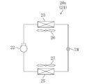
- FIG. 2 is a schematic configuration diagram of a refrigerant circuit of the trailer refrigeration apparatus.
- FIG. 3 is a perspective view showing the entire configuration of the trailer opening and the trailer refrigeration apparatus.
- FIG. 4 is a perspective view of the outer casing.
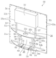
- FIG. 5 is a perspective view showing the trailer refrigeration apparatus with the front cover removed.
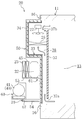
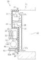
- FIG. 6 is a longitudinal sectional view showing a schematic configuration of the trailer refrigeration apparatus.
- FIG. 7 is a perspective view illustrating the trailer refrigeration apparatus with the front cover removed, and illustrates the flow of outdoor air.
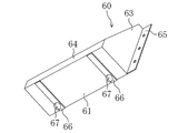
- FIG. 8 is a perspective view of the engine support portion according to the embodiment.
- FIG. 8 is a perspective view of the engine support portion according to the embodiment.
- FIG. 9 is a longitudinal sectional view showing a schematic configuration of the trailer refrigeration apparatus, and shows a state in which the engine support portion is pulled out to the front side.
- FIG. 10 is a perspective view of a modified external casing.
- FIG. 11 is a longitudinal sectional view showing a schematic configuration of a trailer refrigeration apparatus according to a modification.
- FIG. 12 is a longitudinal sectional view showing a schematic configuration of a trailer refrigeration apparatus according to a modified example, and shows a state in which the engine support portion is pulled out to the front side.
- the trailer refrigeration apparatus (20) of this embodiment is mounted on a refrigeration vehicle (10) for transporting frozen foods, fresh foods, and the like on land.
- the refrigeration vehicle (10) includes a trailer (11) that stores cargo such as frozen food, and a tractor (12) that pulls the trailer (11).
- the trailer (11) is formed in a box shape having a vertically long rectangular parallelepiped shape in the front-rear direction and an open front end.
- An interior space (13) is formed inside the trailer (11), and frozen food, fresh food, and the like are stored in the interior space (13).
- a rectangular frame-shaped opening (14) is formed at the front end of the trailer (11).
- a plurality of screwing portions (15, 15,%) are formed on the front end surface of the opening portion (14).
- the plurality of screwing portions (15, 15,...) Are arranged at regular intervals, for example, at 8 locations on each of the four sides of the opening portion (14).
- the trailer refrigeration apparatus (20) constitutes a cooling apparatus for cooling the air in the internal space (13) of the refrigeration vehicle (10).
- the trailer refrigeration apparatus (20) includes a cooling unit (20a) for cooling the internal space (13) of the trailer (11).
- the cooling unit (20a) includes a refrigerant circuit (21) filled with a refrigerant.
- a compressor (22), a condenser (23), an expansion valve (24), and an evaporator (25) are connected to the refrigerant circuit (21).
- a refrigerant is circulated to perform a vapor compression refrigeration cycle.
- An outside fan (26) is provided in the vicinity of the condenser (23).
- An internal fan (27) is provided in the vicinity of the evaporator (25). In the evaporator (25), the internal air conveyed by the internal fan (27) and the refrigerant exchange heat.
- the evaporator (25) constitutes a cooling unit for cooling the air in the interior space (13) of the trailer (11).
- the expansion valve (24) is configured such that the opening degree can be adjusted, and constitutes a decompression mechanism for decompressing the refrigerant.
- the trailer refrigerating apparatus (20) has a casing unit (31) attached to the open portion (14) of the trailer (11).
- the casing unit (31) includes a front cover (32), an external casing (50), and an internal casing (33).
- the front cover (32) is configured to be detachable from the front surface of the external casing (50).
- the front cover (32) is configured by an arcuate plate-like member in which an intermediate portion in the width direction (left-right direction in FIG. 3) bulges forward.
- the side part (32a, 32a) of the width direction both ends is hold
- the front cover (32) is provided with one central inlet (32b) and two side inlets (32c, 32c).
- the central introduction port (32b) is formed in the approximate center of the front cover (32).
- the side introduction ports (32c, 32c) are formed on the lower side of the front cover (32) and on the left and right ends, respectively.
- the outside casing (50) is provided outside the trailer (11) and constitutes a main body of the casing unit (casing) (31).
- the outside-compartment casing (50) is formed in a substantially planar shape that closes the open portion (14) of the trailer (11) and is fixed to the outer edge of the open portion (14).
- the outside casing (50) is made of an aluminum material.
- the outside casing (50) has a square plate-shaped base portion (51) and a bulging portion (52) formed in an upper portion of the base portion (51) (for example, FIG. 4 to FIG. 6).
- the base part (51) is configured by connecting three plate-like divided bodies (51a, 51b, 51c) in the vertical direction. That is, the base part (51) is located between the lower base part (51a) near the lower part, the upper base part (51b) near the upper part, and the lower base part (51a) and the upper base part (51b). It is comprised by the intermediate base part (51c) located.
- a plurality of bolt holes (53a, 53a,%) Through which the bolts (16) are inserted are formed in the outer edge portion (53) of the base portion (51).
- the plurality of bolt holes (53a, 53a,...) are arranged at equal intervals, for example, at eight locations on each of the four sides of the outer edge portion (53) of the base portion (51).
- the outer casing (50) is a bolt (16) that penetrates the bolt hole (53a) with the outer edge (53) of the base part (51) and the open part (14) of the trailer (11) in close contact with each other. Is fixed to the trailer (11) by fastening it to the screwing portion (15).
- the open part (14) of the trailer (11) is closed. That is, the outside casing (50) functions as a closing member that closes the opening (14) of the trailer (11). Moreover, in the state which fixed the outer casing (50) to the trailer (11), the open part (14) of the trailer (11) is reinforced by the outer edge part (53) of the outer casing (50). That is, the outside casing (50) also functions as a reinforcing member for the open portion (14) of the trailer (11).
- the bulging portion (52) is made of an aluminum material that is integral with the base portion (51), and bulges forward from the base portion (51).
- the bulging portion (52) is formed in a box shape having a rectangular parallelepiped shape that is flat in the front-rear direction and opened on the rear surface side (see FIG. 6).
- the bulging portion (52) may be made of, for example, a resin material and integrally connected to the base portion (51).
- the outer casing (50) includes a lower support member (54) and an upper support member (55).
- the lower support member (54) is provided near the lower end of the base portion (51), and the upper support member (55) is swelled with an intermediate portion (lower support member (54) in the vertical direction of the base portion (51). (Between the outlet (52)).
- Each support member (54, 55) has an arcuate plate-like plate portion (54a, 55a).
- the plate portions (54a, 55a) are formed in a circular arc shape on the front side and linearly on the rear side along the front surface of the base portion (51).
- Each support member (54, 55) has a bent portion (54b, 55b) bent upward from the rear end of the plate portion (54a, 55a).
- the bent portions (54b, 55b) are formed in a plate shape extending in the left-right direction.
- Each support member (54, 55) is fixed to the base portion (51) by the bent portions (54b, 55b) being fixed to the base portion (51) by rivets.
- the plate portion (55a) of the upper support member (55) is provided with a communication port (55c) at an intermediate portion in the left-right direction.
- the first machine chamber (35) is partitioned between the lower support member (54) and the upper support member (55).
- a second machine chamber (36) is defined above the upper support member (55).
- the first machine chamber (35) and the second machine chamber (36) communicate with each other via the communication port (55c) of the upper support member (55).
- the first machine room (35) communicates with the two side introduction ports (32c, 32c) described above, and the second machine room (36) communicates with the center introduction port (32b) described above. .
- the outer casing (50) includes two lower pillars (56) and two upper pillars (57).
- the lower column portion (56) is interposed between the lower support member (54) and the upper support member (55).
- the upper column part (57) is interposed between the upper support member (55) and the bulging part (52).
- Each column portion (56, 57) is made of an aluminum material and is formed in a prismatic shape extending vertically.
- a generator (40), an engine (41), a battery (42), and a plurality of electrical component boxes (43, 44) are provided in the first machine room (35) described above. Yes.
- the first machine room (35) is provided with an engine support part (60), which will be described in detail later.
- a generator (40) and an engine (41) are installed on the engine support part (60). Yes.
- the engine (41) drives the generator (40), and the generator (40) generates electric power for driving the above-described compressor (22) and the like. That is, an engine generator in which the generator (40) and the engine (41) are integrally formed is mounted in the first machine room (35).
- the first electrical component box (43) is provided in the left space of the generator (40), and the second electrical component box (in the right space of the engine (41) ( 44) is provided.
- the second machine room (36) is provided with two compressors (22), a condenser (23), a radiator (45), two external fans (26), and an electrical component box (46).
- two compressors (22) are installed at an intermediate position in the left-right direction of the upper support member (55).
- a radiator (45) and a condenser (23) are disposed in front of the compressor (22).
- the condenser (23) is disposed so as to straddle the two upper pillars (57).
- the central inlet (32b) of the front cover (32) is located in front of the condenser (23).
- the radiator (45) is disposed on the rear side of the condenser (23), and constitutes an air-cooled radiator for radiating heat from the engine (41).
- the two external fans (26, 26) are arranged near the left and right ends of the upper support member (55) so as to sandwich the two compressors (22).
- the external fan (2) is a so-called propeller fan, and its rotation shaft extends to the left and right.
- a propeller is connected to the end near the compressor (22) and a motor is connected to the opposite end of the rotating shaft of the external fan (26).
- a third electrical component box (46) is provided in the space on the upper right side.
- the internal casing (33) is provided on the back side of the external casing (50) so as to face the internal space (13) of the trailer (11).
- the internal casing (33) is made of, for example, an FRP (glass fiber reinforced plastic) material. Note that the internal casing (33) can be made of other resin material, metal material, or the like.
- the internal casing (33) has a shape along the back surface of the external casing (50).
- the front surface of the inner casing (33) is spaced a predetermined distance from the rear surface of the outer casing (50), and a heat insulating member (34) is provided between the inner casing (33) and the outer casing (50). Is formed.
- the heat insulating member (34) is integrated with the casing unit (31) by forming a sealed space between the outer casing (50) and the inner casing (33) and then filling the sealed space with foamed resin. Formed.
- a partition member (37) is attached to the back side of the internal casing (33).
- the partition member (37) is disposed so as to have a predetermined distance from each of the back surface of the internal casing (33), the upper inner wall of the trailer (11), and the lower inner wall of the trailer (11).
- the inflow port (37a) is formed below the partition member (37)
- the outflow port (37b) is formed above the partition member (37).
- an internal air flow path (38) is formed between the internal casing (33) and the partition member (37) so as to straddle the inflow port (37a) and the outflow port (37b).
- the inside air flow path (38) is provided with the evaporator (25) and the internal fan (27) described above.
- the evaporator (25) is disposed on the back side of the bulging portion (52) so as to straddle between the inner casing (33) and the partition member (37) and supported by the inner casing (33). ing.
- the internal fan (27) is provided above the evaporator (25).
- the outer casing (50) is provided with the engine support (60) on which the engine (41) and the generator (40) are installed.
- the engine support part (60) is installed on the upper surface of the lower support member (54) between the two lower support members (54, 54) (see FIG. 4).
- the engine support portion (60) of the present embodiment has a box shape in which the upper side and the oblique front side are opened, and the outer shape is generally formed in a triangular column shape (see FIGS. 4 and 8). Moreover, the engine support part (60) of this embodiment is comprised with the aluminum material.
- the engine support portion (60) includes a bottom plate portion (61), a back plate portion (62), a pair of side plate portions (63, 63), a front frame plate portion (64), and a pair of mounting plate portions (65, 65). have.
- the bottom plate portion (61) is formed in a rectangular shape extending left and right so as to straddle the pair of lower column portions (56, 56).
- a pair of wheel holding plates (66, 66) and wheel portions held by the wheel holding portions (66, 66), respectively. (67, 67) are provided on the lower surface of the bottom plate portion (61) (that is, the lower portion of the engine support portion (60)).
- the wheel holding plates (66, 66) are formed in, for example, a plate shape extending in the front-rear direction, and are fixed to the lower surface of the bottom plate portion (61).
- the two wheel holding portions (66, 66) are arranged in parallel so as to have a predetermined interval.
- the wheel portion (67) is configured to be rotatable with the left-right direction as an axial direction.
- one wheel holding part (66) is provided with one wheel part (67), but one wheel holding part (66) is provided with two or more wheel parts (67).
- the back plate portion (62) is formed in a substantially rectangular shape.
- a part of the base part (51) described above is located on the back side of the back plate part (62), and the back plate part (62) and the base part (51) of the engine support part (60) Can be contacted.
- an opening for fitting the back plate portion (62) is formed in the back portion of the back plate portion (62) in the base portion (51), and this opening is formed by the back plate portion (62). You may employ
- the pair of side plate portions (63, 63) are formed in a substantially right triangle shape in which the upper end portion and the front end portion are notched flat. Then, the bottom plate portion (61) is formed so as to straddle the lower side of both side plate portions (63, 63), and the back plate portion ( 62) is formed. Furthermore, the said front frame board part (64) is extended and formed so that it may straddle the edge of the front end of both side board parts (63,63).
- the pair of mounting plate portions (65, 65) protrude from the side plate portions (63, 63) to the left and right outer sides of the engine support portion (60), respectively.
- Each of the mounting plate portions (65, 65) is formed in a long plate shape extending from the upper end to the lower end of the engine support portion (60), and the back surface thereof can come into contact with the base portion (51).
- the contact surfaces of the mounting plate portions (65, 65) and the base portion (51) corresponding to the mounting plate portions (65, 65) are fixed by fastening members. That is, the engine support part (60) can be attached to and detached from the external casing (50) by fixing each mounting plate part (65, 65) and the base part (51) with a fastening member or releasing the fixing. It has become.
- Each rail groove (70) has two rails (71, 71).
- Each rail (71, 71) has a rod shape extending in the front-rear direction, and has a longitudinal section formed in a rectangular shape, for example. Between the two adjacent rails (71, 71), a groove is formed along the rails (71, 71) so that the wheel portion (67) can be rotatably fitted. That is, the rail groove portion (70) is disposed below the engine support portion (60) and extends in the front-rear direction so as to be fitted with the wheel portions (67, 67).
- the engine support part (60) can be pulled out in the direction of the front side of the trailer (11) with respect to the outer casing (50).
- the rail groove part (70) comprises the guide member for guiding an engine support part (60) back and forth (it mentions later for details).
- the refrigerant compressed by the compressor (22) flows through the condenser (23).
- the condenser (23) the refrigerant dissipates heat to the outside air and condenses.
- the condensed refrigerant is decompressed by passing through the expansion valve (24), and the decompressed refrigerant flows through the evaporator (25).
- the evaporator (25) the refrigerant absorbs heat from the internal air and evaporates.
- the evaporated refrigerant is compressed again by the compressor (22).
- the internal air in the internal space (13) is sucked into the internal air flow path (38) from the inlet (37a).
- the air sucked into the inside air flow path (38) flows upward and passes through the evaporator (25).
- the internal air is cooled by exchanging heat with the refrigerant.
- the internal air cooled by the evaporator (25) flows out from the outlet (37b) into the internal space (S) and is used for refrigeration / freezing of cargo and the like.
- outside (outdoor) air is sucked into the machine room (35.36). Specifically, the outside air is sucked into the two side introduction ports (32c, 32c) and the central introduction port (32b) of the front cover (32).
- the air introduced into the first machine room (35) from the left side inlet (32c) passes around the first electrical component box (43). Then, it flows over the engine support (60) and is sent to the vicinity of the generator (40) and the engine (41). Also, the air introduced into the first machine room (35) from the right side inlet (32c) out of the two side inlets (32c, 32c) flows around the second electrical component box (44).
- the air sucked into the second machine room (36) from the central inlet (32b) passes through the condenser (23).
- the refrigerant dissipates heat to the outside air and condenses.
- the air that has passed through the condenser (23) flows around the radiator (45), is used for cooling the radiator (45), and merges with the air that has passed through the communication port (55c).
- the air after merging in the second machine room (36) is diverted in the left-right direction so as to flow around the two compressors (22, 22).
- the air diverted to the left side passes through the upper end opening in the front cover (32) and is discharged to the outside of the external casing (50).
- the air divided to the right side passes through the third electrical component box (46), then passes through the upper end opening in the front cover (32) and is discharged to the outside of the external casing (50).
- the engine (41) and the generator (40) which are relatively heavy, can be pulled forward together with the engine support (60) with respect to the external casing (50). Therefore, during maintenance of the engine (41) and generator (40), the upper support member (55) and other components of the outer casing (50) can be prevented from becoming an obstacle, improving the maintenance work efficiency. it can.
- the wheel portion (67) is provided at the lower portion of the engine support portion (60), and the wheel portion (67) is fitted into the rail groove portion (70). For this reason, a wheel part (67) can be rotated so that a rail groove part (70) may be followed, and a drawer / push-in operation
- the engine support part (60) is made of an aluminum material, the engine support part (60) can be reduced in weight. Therefore, the pulling out / pushing-in operation of the engine support part (60) can be performed more easily.
- the lower support member (54) of this modification has a shape in which the bulge portion (central portion) is cut off. That is, the lower support member (54) of the modified example forms an excision space (54c) at the center position in the longitudinal direction. Further, on the lower side of the lower support member (54) of the modified example, a first rib (72) is formed in the left part, and a second rib (73) is formed in the right part.
- the engine support portion (60) of the modified example has a different configuration from the above embodiment.
- the engine support part (60) has a bottom plate part (81) and a back plate part (82).
- the bottom plate portion (81) is formed in a rectangular shape extending over the two lower column portions (56, 56).
- the bottom plate portion (81) straddles the left and right portions of the lower support member (54) so as to close the excision space (54c).
- the generator (40) and the engine (41) are installed on the bottom plate (81).
- the back plate portion (82) is configured to be able to contact the base portion (51).
- the left and right end portions of the bottom plate portion (81) and the back plate portion (82) are respectively fixed by fastening members.
- the engine support portion (60) is configured such that the bottom plate portion (81) is fastened to the lower support member (54) and the back plate portion (82) is fastened to the base portion (51). Fixed to 50).
- a pair of fork pocket portions (83, 83) are provided below the engine support portion (60).
- the fork pocket portion (83) is formed in a substantially cylindrical shape extending in the front-rear direction, and an internal space (83a) is formed inside thereof.
- the longitudinal cross-sectional shape (cross-sectional shape perpendicular to the axis) of the internal space (83a) is a rectangular shape that is slightly flat in the vertical direction.
- This internal space (83a) constitutes an engagement hole with which a forklift pawl is engaged.
- An intermediate rib (84) extending in the left-right direction is provided between the fork pocket portions (83, 83).
- the front cover (32) is first removed, and then the engine (41) and the generator (40) are mounted, as in the above embodiment. Remove the pipes to be connected. Thereafter, in the engine support portion (60), the fastening members of the bottom plate portion (81) and the back plate portion (82) are removed, and the engine support portion (60) is detached from the external casing (50).
- the pair of claws (90) provided on the forklift are inserted into the fork pockets (83, 83) of the engine support (60).
- the engine support (60) can be pulled forward by lifting the engine support (60) with the claws (90) of the forklift. Therefore, the engine (41) and the generator (40) can be held in a position protruding forward with respect to the outer casing (50), and the work efficiency of maintenance of the engine (41) and the generator (40) can be improved.
- the present invention is useful for a trailer refrigeration apparatus that cools the interior space of a trailer.
Landscapes
- Engineering & Computer Science (AREA)
- Physics & Mathematics (AREA)
- Thermal Sciences (AREA)
- Mechanical Engineering (AREA)
- Health & Medical Sciences (AREA)
- Public Health (AREA)
- Transportation (AREA)
- Chemical & Material Sciences (AREA)
- Combustion & Propulsion (AREA)
- General Engineering & Computer Science (AREA)
- Devices That Are Associated With Refrigeration Equipment (AREA)
Abstract
ケーシング(31)は、ケーシング(31)の本体部(50)に固定されてエンジン発電機(40,41)が設置されるエンジン支持部(60)を有している。エンジン支持部(60)は、ケーシング(31)の本体部(50)に対してトレーラ(11)の前側の方向に引き出し自在に構成されている。
Description
本発明は、トレーラの庫内空間を冷却するトレーラ用冷凍装置に関するものである。
庫内を冷却する冷凍装置としては、冷凍車両のトレーラ内の庫内空間を冷却するトレーラ用冷凍装置が知られている。特許文献1には、この種のトレーラ用冷凍装置が開示されている。
トレーラ用冷凍装置は、トレーラの前端の開放部に取り付けられるケーシングと、このケーシングに支持されて庫内を冷却する冷却部を有している。冷却部は、冷媒回路に接続される蒸発器で構成されている。即ち、トレーラ用冷凍装置では、冷媒が冷媒回路を循環することで、蒸気圧縮式の冷凍サイクルが行われる。これにより、庫内に設けられた蒸発器では、冷媒が庫内空気から吸熱して蒸発し、その結果、庫内空気が冷却される。
トレーラ用冷凍装置では、ケーシングの支持部にエンジン発電機が設置されている。具体的には、トレーラを閉塞するケーシング本体部には、水平方向や鉛直方向に延びる複数のフレーム部材が設けられ、ケーシングの補強がなされている。そして、これらのフレーム部のうち水平に延びる枠状の支持部に、エンジン発電機が設置されている。
特許文献1に開示のトレーラ用冷凍装置では、上述したように、ケーシング本体部に多数のフレーム部材や他の構成部品(例えば圧縮機や電装品箱等)が設けられる。このため、エンジン発電機のメンテナンスを行う際には、これらの複数のフレーム部材や構成部品等が邪魔となってしまい、メンテナンスの作業効率が低下してしまう虞がある。また、メンテナンスの作業効率を向上させるために、エンジン発電機をケーシング本体部から取り外すことも考えられる。しかしながら、エンジン発電機は比較的重量が大きいため、エンジン発電機の取り外しや取り付け作業に多大な労力を要してしまう。
本発明は、かかる点に鑑みてなされたものであり、その目的は、エンジン発電機を迅速且つ簡便にメンテナンスできるトレーラ用冷凍装置を提供することである。
第1の発明は、トレーラ(11)の前側の開放部(14)に取り付けられるケーシング(31)と、上記トレーラ(11)の庫内空間(13)の空気を冷却する冷却ユニット(20a)と、上記冷却ユニット(20a)へ電力を供給するためのエンジン発電機(40,41)とを備え、上記ケーシング(31)は、該ケーシング(31)の本体部(50)に固定されて上記エンジン発電機(40,41)が設置されるエンジン支持部(60)を有しているトレーラ用冷凍装置を対象とする。そして、上記エンジン支持部(60)は、ケーシング(31)の本体部(50)に対して、トレーラ(11)の前側の方向に引き出し自在に構成されていることを特徴とする。
第1の発明では、トレーラ(11)の前側の開放部(14)にケーシング(31)が取り付けられることで、トレーラ(11)が閉塞される。エンジン発電機(40,41)が運転されると、冷却ユニット(20a)へ電力が供給される。冷却ユニット(20a)が運転されることで、トレーラ(11)の庫内空間(13)が冷却される。
本発明では、エンジン発電機(40,41)が設置されるエンジン支持部(60)が、ケーシング(31)の本体部(50)に対して前方に引き出し自在となっている。これにより、ユーザー等がエンジン発電機(40,41)のメンテナンスを行う際には、エンジン支持部(60)をエンジン発電機(40,41)と共に前方に引き出すことができる。このため、エンジン発電機(40,41)が本体部(50)に対して前寄りに位置するので、エンジン発電機(40,41)のメンテナンス時において、本体部(50)に設けられた補強部材や他の構成部品が邪魔となってしまうことが抑制される。
また、エンジン発電機(40,41)をエンジン支持部(60)と共に前方に引き出すため、比較的大きな重量のエンジン発電機(40,41)を簡易に前方に引き出すことができる。
第2の発明は、第1の発明において、上記ケーシング(31)には、上記エンジン支持部(60)を前後に案内するための案内部材(70)が設けられていることを特徴とする。
第2の発明では、ケーシング(31)に案内部材(70)が設けられる。これにより、エンジン支持部(60)を案内部材(70)に案内させながら、このエンジン支持部(60)を前方に引き出すことができる。従って、比較的大きな重量のエンジン発電機(40,41)を簡易に前方に引き出すことができる。メンテナンスの終了後には、エンジン支持部(60)を案内部材(70)に案内させながら、このエンジン支持部(60)を後方に押し込むことができる。従って、比較的大きな重量のエンジン発電機(40,41)を簡易に元の位置に戻すことができる。
第3の発明は、第2の発明において、上記エンジン支持部(60)の下部には、車輪部(67)が設けられ、上記案内部材は、上記エンジン支持部(60)の下側に配設され、前後方向に延びて上記車輪部(67)が嵌合するレール溝部(70)を有していることを特徴とする。
第3の発明では、エンジン支持部(60)の下部に設けられた車輪部(67)が、レール溝部(70)に嵌合する。これにより、車輪部(67)をレール溝部(70)に沿って転がしながら、エンジン支持部(60)を前方に引き出すことができる。従って、比較的大きな重量のエンジン発電機(40,41)を簡易且つ円滑に前方に引き出すことができる。メンテナンスの終了後には、車輪部(67)をレール溝部(70)に沿って転がしながら、エンジン支持部(60)を後方に押し込むことができる。従って、比較的大きな重量のエンジン発電機(40,41)を簡易に元の位置に戻すことができる。
第4の発明は、第1の発明において、上記エンジン支持部(60)の下部には、前後方向に延び且つ縦断面が略矩形状の内部空間(83a)が形成されていることを特徴とする。
第4の発明のエンジン支持部(60)には、その下部に内部空間(83a)が形成される。この内部空間(83a)は前後方向に延びており、且つその縦断面が略矩形状に形成されている。このため、この内部空間(83a)に、例えばフォークリフト等の爪を挿入することで、エンジン支持部(60)をフォークリフトで支持しながら、前方に引き出すことができる。
第5の発明は、第1乃至第4のいずれか1つの発明において、上記エンジン支持部(60)は、アルミニウム材料で構成されていることを特徴とする。
第5の発明では、エンジン支持部(60)がアルミニウム材料で構成されることにより、エンジン支持部(60)の軽量化が図られる。このため、エンジン発電機(40,41)のメンテナンス時において、より簡便にエンジン支持部(60)を前方に引き出すことができる。
第1の発明では、比較的大きな重量のエンジン発電機(40,41)をエンジン支持部(60)と共に、ケーシング(31)の本体部(50)に対して前方に引き出すことができる。従って、エンジン発電機(40,41)のメンテナンス時において、本体部(50)に配設された補強部材や他の構成部品等が邪魔となることを抑制でき、メンテナンスの作業効率を向上できる。
特に、第2の発明では、エンジン支持部(60)を案内部材(70)によって前後に案内することができるため、エンジン支持部(60)の引き出し/押し込み作業を容易且つ確実に行うことができる。
更に、第3の発明では、エンジン支持部(60)の下部に車輪部(67)を設け、この車輪部(67)をレール溝部(70)に沿うように回転させることができる。このため、エンジン支持部(60)の引き出し/押し込み作業が更に容易となる。
また、第4の発明では、エンジン支持部(60)の下部に前後に延びる内部空間(83a)を形成したので、この内部空間(83a)にフォークリフトの爪を挿入することができる。従って、フォークリフトによってエンジン支持部(60)を前方に引き出すことができる。
また、第5の発明では、エンジン支持部(60)をアルミニウム材料で構成しているので、エンジン支持部(60)の軽量化を図ることができる。従って、エンジン支持部(60)の引き出し/押し込み作業を更に容易且つ確実に行うことができる。
以下、本発明の実施形態を図面に基づいて詳細に説明する。
図1に示すように、本実施形態のトレーラ用冷凍装置(20)は、冷凍食品や生鮮食品等を陸上輸送するための冷凍車両(10)に搭載されている。冷凍車両(10)は、冷凍食品等の貨物が貯蔵されるトレーラ(11)と、トレーラ(11)を牽引するトラクタ(12)とを有している。
トレーラ(11)は、前後方向に縦長の直方体形状で、且つ前端が開放された箱状に形成されている。トレーラ(11)の内部には、庫内空間(13)が形成されており、この庫内空間(13)に冷凍食品や生鮮食品等が貯蔵される。図3に示すように、トレーラ(11)の前端には、矩形枠状の開放部(14)が形成されている。開放部(14)の前端面には、トレーラ用冷凍装置(20)を取り付けるための複数のネジ止め部(15,15,…)が形成されている。複数のネジ止め部(15,15,…)は、開放部(14)の4つの各辺において、例えば8箇所ずつ等間隔となるように配列されている。
-トレーラ用冷凍装置の構成-
トレーラ用冷凍装置(20)は、冷凍車両(10)の庫内空間(13)の空気を冷却するための冷却装置を構成している。図2に示すように、トレーラ用冷凍装置(20)は、トレーラ(11)の庫内空間(13)を冷却するための冷却ユニット(20a)を有している。冷却ユニット(20a)は、冷媒が充填される冷媒回路(21)を備えている。冷媒回路(21)には、圧縮機(22)と凝縮器(23)と膨張弁(24)と蒸発器(25)とが接続されている。冷媒回路(21)では、冷媒が循環することで蒸気圧縮式の冷凍サイクルが行われる。凝縮器(23)の近傍には、庫外ファン(26)が設けられている。凝縮器(23)では、庫外ファン(26)によって搬送される庫外(室外)空気と冷媒とが熱交換する。蒸発器(25)の近傍には、庫内ファン(27)が設けられている。蒸発器(25)では、庫内ファン(27)によって搬送される庫内空気と冷媒とが熱交換する。蒸発器(25)は、トレーラ(11)の庫内空間(13)の空気を冷却するための冷却部を構成している。膨張弁(24)は、開度が調節可能に構成され、冷媒を減圧するための減圧機構を構成している。
トレーラ用冷凍装置(20)は、冷凍車両(10)の庫内空間(13)の空気を冷却するための冷却装置を構成している。図2に示すように、トレーラ用冷凍装置(20)は、トレーラ(11)の庫内空間(13)を冷却するための冷却ユニット(20a)を有している。冷却ユニット(20a)は、冷媒が充填される冷媒回路(21)を備えている。冷媒回路(21)には、圧縮機(22)と凝縮器(23)と膨張弁(24)と蒸発器(25)とが接続されている。冷媒回路(21)では、冷媒が循環することで蒸気圧縮式の冷凍サイクルが行われる。凝縮器(23)の近傍には、庫外ファン(26)が設けられている。凝縮器(23)では、庫外ファン(26)によって搬送される庫外(室外)空気と冷媒とが熱交換する。蒸発器(25)の近傍には、庫内ファン(27)が設けられている。蒸発器(25)では、庫内ファン(27)によって搬送される庫内空気と冷媒とが熱交換する。蒸発器(25)は、トレーラ(11)の庫内空間(13)の空気を冷却するための冷却部を構成している。膨張弁(24)は、開度が調節可能に構成され、冷媒を減圧するための減圧機構を構成している。
図3~図6に示すように、トレーラ用冷凍装置(20)は、トレーラ(11)の開放部(14)に取り付けられるケーシングユニット(31)を有している。ケーシングユニット(31)は、前面カバー(32)と庫外ケーシング(50)と庫内ケーシング(33)とを有している。
〈前面カバー〉
前面カバー(32)は、庫外ケーシング(50)の前面に着脱自在に構成されている。前面カバー(32)は、幅方向(図3における左右方向)の中間部位が前方に膨出する弓形の板状部材で構成されている。前面カバー(32)は、幅方向両端の側辺部(32a,32a)が庫外ケーシング(50)に保持される。これにより、前面カバー(32)の背面と庫外ケーシング(50)の前面との間には、各種の構成機器(詳細は後述する)が収容される機器室(35,36)が形成される。
前面カバー(32)は、庫外ケーシング(50)の前面に着脱自在に構成されている。前面カバー(32)は、幅方向(図3における左右方向)の中間部位が前方に膨出する弓形の板状部材で構成されている。前面カバー(32)は、幅方向両端の側辺部(32a,32a)が庫外ケーシング(50)に保持される。これにより、前面カバー(32)の背面と庫外ケーシング(50)の前面との間には、各種の構成機器(詳細は後述する)が収容される機器室(35,36)が形成される。
また、前面カバー(32)には、1つの中央導入口(32b)と2つの側方導入口(32c,32c)が設けられている。中央導入口(32b)は、前面カバー(32)のほぼ中央に形成されている。側方導入口(32c,32c)は、前面カバー(32)の下側寄り且つ左右両端寄りにそれぞれ形成されている。
〈庫外ケーシング〉
庫外ケーシング(50)は、トレーラ(11)の外側に設けられており、ケーシングユニット(ケーシング)(31)の本体部を構成している。庫外ケーシング(50)は、トレーラ(11)の開放部(14)を閉塞し且つ該開放部(14)の外縁に固定される略面状に形成されている。庫外ケーシング(50)は、アルミニウム材料で構成されている。庫外ケーシング(50)は、正方形板状のベース部(51)と、このベース部(51)の上方部位に形成される膨出部(52)とを有している(例えば図4~図6を参照)。
庫外ケーシング(50)は、トレーラ(11)の外側に設けられており、ケーシングユニット(ケーシング)(31)の本体部を構成している。庫外ケーシング(50)は、トレーラ(11)の開放部(14)を閉塞し且つ該開放部(14)の外縁に固定される略面状に形成されている。庫外ケーシング(50)は、アルミニウム材料で構成されている。庫外ケーシング(50)は、正方形板状のベース部(51)と、このベース部(51)の上方部位に形成される膨出部(52)とを有している(例えば図4~図6を参照)。
ベース部(51)は、3つの板状の分割体(51a,51b,51c)が上下方向に繋ぎ合わされることで構成されている。即ち、ベース部(51)は、下部寄りの下側ベース部(51a)と、上部寄りの上側ベース部(51b)と、下側ベース部(51a)と上側ベース部(51b)との間に位置する中間ベース部(51c)とによって構成されている。
ベース部(51)の外縁部(53)には、ボルト(16)が挿通される複数のボルト穴(53a,53a,…)が形成されている。複数のボルト穴(53a,53a,…)は、ベース部(51)の外縁部(53)の4つの各辺において、例えば8箇所ずつ等間隔となるように配列されている。庫外ケーシング(50)は、ベース部(51)の外縁部(53)とトレーラ(11)の開放部(14)とを密着させた状態で、ボルト穴(53a)を貫通したボルト(16)をネジ止め部(15)に締結することで、トレーラ(11)に固定される。
庫外ケーシング(50)をトレーラ(11)に固定した状態では、トレーラ(11)の開放部(14)が閉塞される。つまり、庫外ケーシング(50)は、トレーラ(11)の開放部(14)を閉塞する閉塞部材として機能する。また、庫外ケーシング(50)をトレーラ(11)に固定した状態では、トレーラ(11)の開放部(14)が庫外ケーシング(50)の外縁部(53)によって補強される。つまり、庫外ケーシング(50)は、トレーラ(11)の開放部(14)の補強部材としても機能する。
膨出部(52)は、ベース部(51)と一体的なアルミニウム材料で構成され、ベース部(51)から前方に膨出している。膨出部(52)は、前後に扁平な直方体状で且つ後面側が開口する箱状に形成されている(図6を参照)。なお、膨出部(52)を例えば樹脂材料で構成し、ベース部(51)と一体的に連結するようにしても良い。
庫外ケーシング(50)は、下側支持部材(54)と上側支持部材(55)とを備えている。下側支持部材(54)は、ベース部(51)の下端寄りに設けられ、上側支持部材(55)は、ベース部(51)の上下方向における中間部(下側支持部材(54)と膨出部(52)との間)に設けられている。各支持部材(54,55)は、弓形板状のプレート部(54a,55a)を有している。プレート部(54a,55a)は、前側が円弧状に形成され、後側はベース部(51)の前面に沿うように直線状に形成されている。各支持部材(54,55)は、プレート部(54a,55a)の後端から上方に屈曲した曲げ部(54b,55b)を有している。曲げ部(54b,55b)は、左右方向に延びる板状に形成されている。各支持部材(54,55)は、曲げ部(54b,55b)がベース部(51)にリベットによって固定されることで、ベース部(51)に固定される。また、上側支持部材(55)のプレート部(55a)には、左右方向の中間部位に連通口(55c)が設けられている。
上述した前面カバー(32)を庫外ケーシング(50)に取り付けた状態では、下側支持部材(54)と上側支持部材(55)との間に第1機械室(35)が区画される。また、上側支持部材(55)の上方に第2機械室(36)が区画される。第1機械室(35)と第2機械室(36)とは、上側支持部材(55)の連通口(55c)を介して互いに連通している。また、第1機械室(35)は、上述した2つの側方導入口(32c,32c)と連通し、第2機械室(36)は、上述した中央導入口(32b)と連通している。
庫外ケーシング(50)は、2本の下側柱部(56)と2本の上側柱部(57)とを備えている。下側柱部(56)は、下側支持部材(54)と上側支持部材(55)との間に介設されている。上側柱部(57)は、上側支持部材(55)と膨出部(52)との間に介設されている。各柱部(56,57)は、アルミニウム材料で構成され、上下に延びる角柱状に形成されている。
図5に示すように、上述した第1機械室(35)には、発電機(40)とエンジン(41)とバッテリー(42)と複数の電装品箱(43,44)とが設けられている。また、第1機械室(35)には、詳細は後述するエンジン支持部(60)が設けられており、このエンジン支持部(60)に発電機(40)及びエンジン(41)が設置されている。エンジン(41)は発電機(40)を駆動するものであり、発電機(40)は上述した圧縮機(22)等を駆動するための電力を発生するものである。つまり、第1機械室(35)には、発電機(40)及びエンジン(41)が一体的に構成される、エンジン発電機が搭載されている。また、第1機械室(35)では、発電機(40)の左側の空間に第1の電装品箱(43)が設けられ、エンジン(41)の右側の空間に第2の電装品箱(44)が設けられている。
第2機械室(36)には、2つの圧縮機(22)と凝縮器(23)とラジエタ(45)と2つの庫外ファン(26)と電装品箱(46)が設けられている。具体的に、第2機械室(36)には、上側支持部材(55)における左右方向の中間位置に2つの圧縮機(22)が設置されている。また、圧縮機(22)の前方には、ラジエタ(45)及び凝縮器(23)が配置されている。凝縮器(23)は、2本の上側柱部(57)に跨るように配設されている。凝縮器(23)の前方には、前面カバー(32)の中央導入口(32b)が位置している。ラジエタ(45)は、凝縮器(23)の後側に配置され、エンジン(41)を放熱するための空冷式の放熱器を構成している。
2つの庫外ファン(26,26)は、2つの圧縮機(22)を挟むように、上側支持部材(55)の左右両端寄りに配置されている。庫外ファン(2)は、いわゆるプロペラファンで構成され、その回転軸が左右に延びている。庫外ファン(26)の回転軸には、圧縮機(22)寄りの端部にプロペラが連結され、逆側の端部にモータが連結している。また、第2機械室(36)では、右側上方寄りの空間に第3の電装品箱(46)が設けられている。
〈庫内ケーシング〉
図6に示すように、庫内ケーシング(33)は、トレーラ(11)の庫内空間(13)に臨むように、庫外ケーシング(50)の背面側に設けられている。庫内ケーシング(33)は、例えばFRP(ガラス繊維強化プラスチック)材料で構成されている。なお、庫内ケーシング(33)を、他の樹脂材料や金属材料等で構成することもできる。庫内ケーシング(33)は、庫外ケーシング(50)の背面に沿うような形状をしている。
図6に示すように、庫内ケーシング(33)は、トレーラ(11)の庫内空間(13)に臨むように、庫外ケーシング(50)の背面側に設けられている。庫内ケーシング(33)は、例えばFRP(ガラス繊維強化プラスチック)材料で構成されている。なお、庫内ケーシング(33)を、他の樹脂材料や金属材料等で構成することもできる。庫内ケーシング(33)は、庫外ケーシング(50)の背面に沿うような形状をしている。
庫内ケーシング(33)の前面は、庫外ケーシング(50)の背面と所定の間隔が置かれており、庫内ケーシング(33)と庫外ケーシング(50)との間に断熱部材(34)が形成されている。断熱部材(34)は、庫外ケーシング(50)と庫内ケーシング(33)との間に密閉空間を形成した後、この密閉空間に発泡樹脂を充填することで、ケーシングユニット(31)に一体的に形成される。
また、庫内ケーシング(33)の背面側には、仕切部材(37)が取り付けられている。仕切部材(37)は、庫内ケーシング(33)の背面、トレーラ(11)の上部内壁、及びトレーラ(11)の下部内壁のそれぞれと所定の距離を置くように配設されている。これにより、仕切部材(37)の下方に流入口(37a)が形成され、仕切部材(37)の上方に流出口(37b)が形成されている。また、庫内ケーシング(33)と仕切部材(37)との間には、流入口(37a)及び流出口(37b)に跨るように、内気流路(38)が形成されている。
内気流路(38)には、上述した蒸発器(25)及び庫内ファン(27)が設けられている。蒸発器(25)は、膨出部(52)の背面側において、庫内ケーシング(33)と仕切部材(37)との間に跨るように配設されて庫内ケーシング(33)に支持されている。庫内ファン(27)は、蒸発器(25)の上方に設けられている。
〈エンジン発電機の引き出し構造について〉
上述したように、庫外ケーシング(50)には、エンジン(41)及び発電機(40)が設置されるエンジン支持部(60)が設けられている。具体的に、エンジン支持部(60)は、2本の下側支持部材(54,54)の間において、下側支持部材(54)の上面に設置されている(図4を参照)。
上述したように、庫外ケーシング(50)には、エンジン(41)及び発電機(40)が設置されるエンジン支持部(60)が設けられている。具体的に、エンジン支持部(60)は、2本の下側支持部材(54,54)の間において、下側支持部材(54)の上面に設置されている(図4を参照)。
本実施形態のエンジン支持部(60)は、上側及び斜め前方側が開放された箱状であり、且つ外形が概ね三角形柱状に形成されている(図4及び図8を参照)。また、本実施形態のエンジン支持部(60)は、アルミニウム材料で構成されている。エンジン支持部(60)は、底板部(61)、背板部(62)、一対の側板部(63,63)、前方枠板部(64)、及び一対の取付板部(65,65)を有している。
底板部(61)は、一対の下側柱部(56,56)に跨るように左右に延びる矩形状に形成されている。底板部(61)の下面(即ち、エンジン支持部(60)の下部)には、一対の車輪保持板(66,66)と、各車輪保持部(66,66)にそれぞれ保持される車輪部(67,67)とが設けられている。車輪保持板(66,66)は、例えば前後に延びる板状に形成され、底板部(61)の下面に固定されている。2つの車輪保持部(66,66)は、所定の間隔を置くように平行に配置されている。車輪部(67)は、左右方向が軸方向となって回転自在に構成されている。なお、本実施形態では、1つの車輪保持部(66)に1つの車輪部(67)を設けているが、1つの車輪保持部(66)に2つ以上の車輪部(67)を設けるようにしても良い。
背板部(62)は、略矩形状に形成されている。本実施形態では、背板部(62)の裏側に上述したベース部(51)の一部が位置しており、エンジン支持部(60)の背板部(62)とベース部(51)とが当接可能となっている。なお、この構成に代わって、ベース部(51)における背板部(62)の裏側の部位に、背板部(62)が嵌合する開口を形成し、背板部(62)によってこの開口を埋める構成を採用しても良い。
一対の側板部(63,63)は、上端部及び前端部が平坦に切り欠かれるような略直角三角形状に形成されている。そして、両者の側板部(63,63)の下辺に跨るように上記の底板部(61)が形成され、両者の側板部(63,63)の後側の辺に跨るように背板部(62)が形成されている。更に、両者の側板部(63,63)の前端の辺に跨るように、上記の前方枠板部(64)が左右に延びて形成されている。
一対の取付板部(65,65)は、各側板部(63,63)からエンジン支持部(60)の左右外方にそれぞれ突出している。各取付板部(65,65)は、エンジン支持部(60)の上端から下端に亘って延びる長板状に形成され、その背面がベース部(51)と当接可能となっている。各取付板部(65,65)、及び各取付板部(65,65)に対応するベース部(51)の当接面は、締結部材によって固定される。即ち、エンジン支持部(60)は、各取付板部(65,65)とベース部(51)とを締結部材によって固定又はこの固定を解除することで、庫外ケーシング(50)に着脱自在となっている。
下側支持部材(54)の上面には、2つのレール溝部(70,70)が形成されている。各レール溝部(70)は、それぞれ2本のレール(71,71)を有している。各レール(71,71)は、前後に延びる棒状であって、例えば縦断面が矩形状に形成されている。隣接する2本のレール(71,71)の間には、両者のレール(71,71)に沿うようにして、上記の車輪部(67)が回転自在に嵌合する溝が形成される。即ち、レール溝部(70)は、エンジン支持部(60)の下側に配設されると共に、前後方向に延びて車輪部(67,67)が嵌合するように構成される。これにより、エンジン支持部(60)は、庫外ケーシング(50)に対して、トレーラ(11)の前側の方向に引き出し可能となっている。また、レール溝部(70)は、エンジン支持部(60)を前後に案内するための案内部材を構成している(詳細は後述する)。
-運転動作-
次に、トレーラ用冷凍装置(20)の運転動作について、図6及び図7を参照しながら説明する。
次に、トレーラ用冷凍装置(20)の運転動作について、図6及び図7を参照しながら説明する。
エンジン(41)によって発電機(40)が駆動されると、発電機(40)で電力が発生する。この電力は、圧縮機(22)、庫外ファン(26)、及び庫内ファン(27)に供給される。冷媒回路(21)では、圧縮機(22)が運転されることで冷凍サイクルが行われる。
詳細には、圧縮機(22)で圧縮された冷媒は、凝縮器(23)を流れる。凝縮器(23)では、冷媒が庫外空気へ放熱して凝縮する。凝縮した冷媒は、膨張弁(24)を通過することで減圧され、減圧後の冷媒は蒸発器(25)を流れる。蒸発器(25)では、冷媒が庫内空気から吸熱して蒸発する。蒸発した冷媒は、圧縮機(22)で再び圧縮される。
庫内ファン(27)が運転されると、庫内空間(13)の庫内空気が流入口(37a)より内気流路(38)に吸い込まれる。内気流路(38)に吸い込まれた空気は、上方へ流れて蒸発器(25)を通過する。蒸発器(25)では、庫内空気が冷媒と熱交換して冷却される。蒸発器(25)で冷却された庫内空気は、流出口(37b)より庫内空間(S)へ流出し、貨物等の冷蔵/冷凍に利用される。
一方、庫外ファン(26)が運転されると、庫外(室外)空気が機械室(35.36)に吸い込まれる。詳細には、庫外空気は、前面カバー(32)の2つの側方導入口(32c,32c)と中央導入口(32b)に吸い込まれる。2つの側方導入口(32c,32c)のうち左側の側方導入口(32c)から第1機械室(35)に導入された空気は、第1電装品箱(43)の周囲を通過し、エンジン支持部(60)の上方を流れて発電機(40)及びエンジン(41)の近傍へ送られる。また、2つの側方導入口(32c,32c)のうち右側の側方導入口(32c)から第1機械室(35)に導入された空気は、第2電装品箱(44)の周囲を通過し、エンジン支持部(60)の上方を流れてエンジン(41)及び発電機(40)の近傍へ送られる。エンジン(41)及び発電機(40)の近傍を空気が流れると、エンジン(41)や発電機(40)が空気によって冷却される。エンジン(41)及び発電機(40)の冷却に利用された空気は、連通口(55c)内を上方に流れて第2機械室(36)へ送られる。
また、中央導入口(32b)から第2機械室(36)に吸い込まれた空気は、凝縮器(23)を通過する。凝縮器(23)では、冷媒が庫外空気に放熱して凝縮する。凝縮器(23)を通過した空気は、ラジエタ(45)の周囲を流れてラジエタ(45)の冷却に利用され、連通口(55c)を通過した空気と合流する。
第2機械室(36)で合流した後の空気は、2つの圧縮機(22,22)の周囲を流れるように、左右方向に分流する。左側に分流した空気は、前面カバー(32)内の上端開口を通過して庫外ケーシング(50)の外部へ放出される。右側に分流した空気は、第3電装品箱(46)を通過した後、前面カバー(32)内の上端開口を通過して庫外ケーシング(50)の外部へ放出される。
-エンジン発電機のメンテナンスについて-
エンジン(41)及び発電機(40)のメンテナンスを行う際には、まず、図3に示す前面カバー(32)を庫外ケーシング(50)から取り外す。次いで、エンジン(41)や発電機(40)に連結する配管等を取り外す。その後、エンジン支持部(60)の取付板部(65)において、締結部材の締結を解除し、エンジン支持部(60)を庫外ケーシング(50)から脱着する。この状態のエンジン支持部(60)を前側に引っ張ると、車輪部(67)が転がりエンジン支持部(60)が前方に移動する。このように、車輪部(67)をレール溝部(70)に沿うように引き出すことで、比較的大きな重量のエンジン(41)及び発電機(40)を容易且つ円滑に前方に引き出すことができる。
エンジン(41)及び発電機(40)のメンテナンスを行う際には、まず、図3に示す前面カバー(32)を庫外ケーシング(50)から取り外す。次いで、エンジン(41)や発電機(40)に連結する配管等を取り外す。その後、エンジン支持部(60)の取付板部(65)において、締結部材の締結を解除し、エンジン支持部(60)を庫外ケーシング(50)から脱着する。この状態のエンジン支持部(60)を前側に引っ張ると、車輪部(67)が転がりエンジン支持部(60)が前方に移動する。このように、車輪部(67)をレール溝部(70)に沿うように引き出すことで、比較的大きな重量のエンジン(41)及び発電機(40)を容易且つ円滑に前方に引き出すことができる。
以上のようにして、エンジン支持部(60)を庫外ケーシング(50)に対して前方へ引き出すと、図9に示すように、エンジン(41)や発電機(40)が庫外ケーシング(50)に対して前方に突出した位置となる。このため、エンジン(41)の所定部位(例えばインジェクター部分)や発電機(40)のメンテナンス時において、上側支持部材(55)や他の部品等がメンテナンスの邪魔となってしまうことを抑制できる。
メンテナンスの終了後には、エンジン支持部(60)を後方に押し込む。これにより、車輪部(67)が転がりエンジン支持部(60)が後方に移動する。このように、車輪部(67)をレール溝部(70)に沿うように押し込むことで、比較的大きな重量のエンジン(41)及び発電機(40)を容易且つ円滑に後方へ押し込んで元の位置に戻すことができる。
-実施形態の効果-
上記実施形態では、比較的大重量となるエンジン(41)及び発電機(40)をエンジン支持部(60)と共に、庫外ケーシング(50)に対して前方に引き出すことができる。従って、エンジン(41)及び発電機(40)のメンテナンス時において、庫外ケーシング(50)の上側支持部材(55)や他の構成部品が邪魔となることを抑制でき、メンテナンスの作業効率を向上できる。
上記実施形態では、比較的大重量となるエンジン(41)及び発電機(40)をエンジン支持部(60)と共に、庫外ケーシング(50)に対して前方に引き出すことができる。従って、エンジン(41)及び発電機(40)のメンテナンス時において、庫外ケーシング(50)の上側支持部材(55)や他の構成部品が邪魔となることを抑制でき、メンテナンスの作業効率を向上できる。
特に、上記実施形態では、エンジン支持部(60)の下部に車輪部(67)を設け、この車輪部(67)をレール溝部(70)に嵌合させている。このため、車輪部(67)をレール溝部(70)に沿うように回転させることができ、エンジン支持部(60)の引き出し/押し込み作業を容易に行うことができる。
更に、エンジン支持部(60)をアルミニウム材料で構成しているので、エンジン支持部(60)の軽量化を図ることができる。従って、エンジン支持部(60)の引き出し/押し込み作業を更に容易に行うことができる。
〈実施形態の変形例〉
上述した実施形態の変形例について図10~図12を参照しながら説明する。この変形例の下側支持部材(54)は、その膨出部(中央部)が切除された形状をしている。つまり、変形例の下側支持部材(54)は、長手方向の中央位置に切除空間(54c)を形成している。また、変形例の下側支持部材(54)の下側には、左側の部位に第1リブ(72)が形成され、右側の部位に第2リブ(73)が形成されている。
上述した実施形態の変形例について図10~図12を参照しながら説明する。この変形例の下側支持部材(54)は、その膨出部(中央部)が切除された形状をしている。つまり、変形例の下側支持部材(54)は、長手方向の中央位置に切除空間(54c)を形成している。また、変形例の下側支持部材(54)の下側には、左側の部位に第1リブ(72)が形成され、右側の部位に第2リブ(73)が形成されている。
変形例のエンジン支持部(60)は、上記実施形態と異なる構成をしている。具体的には、エンジン支持部(60)は、底板部(81)と背板部(82)とを有している。底板部(81)は、2つの下側柱部(56,56)に亘って延びる矩形状に形成されている。そして、底板部(81)は、切除空間(54c)を塞ぐように、下側支持部材(54)の左右両側の部位に跨っている。図10では図示を省略しているが、底板部(81)には発電機(40)及びエンジン(41)が設置されている。背板部(82)は、ベース部(51)と当接可能に構成されている。
変形例のエンジン支持部(60)は、底板部(81)及び背板部(82)の左右の端部が、それぞれ締結部材によって固定される。つまり、エンジン支持部(60)は、底板部(81)が下側支持部材(54)に締結され、背板部(82)がベース部(51)に締結されることで、庫外ケーシング(50)に固定される。
また、エンジン支持部(60)の下側には、一対のフォークポケット部(83,83)が設けられている。フォークポケット部(83)は、前後に延びる略筒状に形成され、その内側に内部空間(83a)形成している。内部空間(83a)の縦断面形状(軸直角断面形状)は、上下にやや扁平な矩形状をしている。この内部空間(83a)は、フォークリフトの爪が係合する係合穴を構成している。また、両者のフォークポケット部(83,83)の間には、左右方向に延びる中間リブ(84)が設けられている。
この変形例において、エンジン(41)及び発電機(40)のメンテナンスを行う際には、上記実施形態と同様、まず前面カバー(32)を取り外し、次いでエンジン(41)や発電機(40)に連結する配管等を取り外す。その後、エンジン支持部(60)において、底板部(81)や背板部(82)の締結部材を取り外し、エンジン支持部(60)を庫外ケーシング(50)から脱着する。
この状態において、フォークリフトに設けられる一対の爪(90)を、エンジン支持部(60)の各フォークポケット(83,83)にそれぞれ挿入する。これにより、図12に示すように、フォークリフトの爪(90)によってエンジン支持部(60)を持ち上げるようにして、このエンジン支持部(60)を前方に引き出すことができる。よって、エンジン(41)や発電機(40)を庫外ケーシング(50)に対して前方に突出した位置に保持でき、エンジン(41)や発電機(40)のメンテナンスの作業効率を向上できる。
なお、以上の実施形態は、本質的に好ましい例示であって、本発明、その適用物、あるいはその用途の範囲を制限することを意図するものではない。
以上説明したように、本発明は、トレーラの庫内空間を冷却するトレーラ用冷凍装置について有用である。
11 トレーラ
13 庫内空間
14 開放部
20 トレーラ用冷凍装置
20a 冷却ユニット
25 蒸発器(冷却部)
31 ケーシングユニット(ケーシング)
50 庫外ケーシング(本体部)
60 エンジン支持部
67 車輪部
70 レール溝部(案内部材)
83a 内部空間
13 庫内空間
14 開放部
20 トレーラ用冷凍装置
20a 冷却ユニット
25 蒸発器(冷却部)
31 ケーシングユニット(ケーシング)
50 庫外ケーシング(本体部)
60 エンジン支持部
67 車輪部
70 レール溝部(案内部材)
83a 内部空間
Claims (5)
- トレーラ(11)の前側の開放部(14)に取り付けられるケーシング(31)と、該トレーラ(11)の庫内空間(13)の空気を冷却する冷却ユニット(20a)と、上記冷却ユニット(20a)へ電力を供給するためのエンジン発電機(40,41)とを備え、上記ケーシング(31)は、該ケーシング(31)の本体部(50)に固定されて上記エンジン発電機(40,41)が設置されるエンジン支持部(60)を有しているトレーラ用冷凍装置であって、
上記エンジン支持部(60)は、ケーシング(31)の本体部(50)に対して、上記トレーラ(11)の前側の方向に引き出し自在に構成されていることを特徴とするトレーラ用冷凍装置。 - 請求項1において、
上記ケーシング(31)には、上記エンジン支持部(60)を前後に案内するための案内部材(70)が設けられていることを特徴とするトレーラ用冷凍装置。 - 請求項2において、
上記エンジン支持部(60)の下部には、車輪部(67)が設けられ、
上記案内部材は、上記エンジン支持部(60)の下側に配設され、前後方向に延びて上記車輪部(67)が嵌合するレール溝部(70)を有していることを特徴とするトレーラ用冷凍装置。 - 請求項1において、
上記エンジン支持部(60)の下部には、前後方向に延び且つ縦断面が略矩形状の内部空間(83a)が形成されていることを特徴とするトレーラ用冷凍装置。 - 請求項1乃至4のいずれか1つにおいて、
上記エンジン支持部(60)は、アルミニウム材料で構成されていることを特徴とするトレーラ用冷凍装置。
Priority Applications (3)
| Application Number | Priority Date | Filing Date | Title |
|---|---|---|---|
| EP10785923.3A EP2442054B1 (en) | 2009-06-10 | 2010-06-04 | Refrigeration device for trailer |
| US13/377,344 US9132765B2 (en) | 2009-06-10 | 2010-06-04 | Trailer refrigerating apparatus |
| CN2010800250632A CN102449415A (zh) | 2009-06-10 | 2010-06-04 | 拖车用制冷装置 |
Applications Claiming Priority (2)
| Application Number | Priority Date | Filing Date | Title |
|---|---|---|---|
| JP2009139513A JP5453943B2 (ja) | 2009-06-10 | 2009-06-10 | トレーラ用冷凍装置 |
| JP2009-139513 | 2009-06-10 |
Publications (1)
| Publication Number | Publication Date |
|---|---|
| WO2010143391A1 true WO2010143391A1 (ja) | 2010-12-16 |
Family
ID=43308654
Family Applications (1)
| Application Number | Title | Priority Date | Filing Date |
|---|---|---|---|
| PCT/JP2010/003754 Ceased WO2010143391A1 (ja) | 2009-06-10 | 2010-06-04 | トレーラ用冷凍装置 |
Country Status (5)
| Country | Link |
|---|---|
| US (1) | US9132765B2 (ja) |
| EP (1) | EP2442054B1 (ja) |
| JP (1) | JP5453943B2 (ja) |
| CN (1) | CN102449415A (ja) |
| WO (1) | WO2010143391A1 (ja) |
Families Citing this family (10)
| Publication number | Priority date | Publication date | Assignee | Title |
|---|---|---|---|---|
| CN105050839B (zh) * | 2013-03-19 | 2017-10-31 | 三菱电机株式会社 | 车用空调装置 |
| FR3029485B1 (fr) * | 2014-12-03 | 2018-03-16 | Alstom Transport Technologies | Dispositif aeraulique de refroidissement d'un element d'un vehicule ferroviaire et vehicule ferroviaire correspondant |
| WO2016153841A1 (en) * | 2015-03-20 | 2016-09-29 | Carrier Corporation | Transportation refrigeration unit with multiple compressors |
| US20160280043A1 (en) * | 2015-03-25 | 2016-09-29 | Thermo King Corporation | Low profile refrigerated transport unit |
| AT516249B1 (de) * | 2015-05-05 | 2016-04-15 | Ge Jenbacher Gmbh & Co Og | Anordnung aus einem Genset und einem Container |
| EP3440418B1 (en) | 2016-04-05 | 2026-01-07 | Carrier Corporation | Tractor trailer system |
| JP6953250B2 (ja) * | 2017-09-15 | 2021-10-27 | 三菱重工サーマルシステムズ株式会社 | 輸送用冷凍ユニット及び輸送用冷凍ユニット組立方法 |
| CN108278839A (zh) * | 2018-02-07 | 2018-07-13 | 安徽海博家电科技有限公司 | 一种冰箱用底缸 |
| EP3537068A1 (en) * | 2018-03-06 | 2019-09-11 | Arkema France | Cooling system and refrigerator box |
| JP7470581B2 (ja) | 2020-06-26 | 2024-04-18 | 三菱重工業株式会社 | 輸送用冷凍機械、及び輸送機械 |
Citations (6)
| Publication number | Priority date | Publication date | Assignee | Title |
|---|---|---|---|---|
| JPS6065587U (ja) * | 1983-10-11 | 1985-05-09 | 日本建鐵株式会社 | 冷凍冷蔵オ−プンシヨ−ケ−スの台枠 |
| JPS61194174U (ja) * | 1985-05-27 | 1986-12-03 | ||
| JPS6291773A (ja) * | 1985-10-17 | 1987-04-27 | ダイキン工業株式会社 | コンテナ用冷凍装置 |
| JPH01189482A (ja) * | 1988-01-21 | 1989-07-28 | Mitsubishi Electric Corp | 冷蔵庫 |
| JP2001351162A (ja) * | 2000-06-08 | 2001-12-21 | Shibaura Mechatronics Corp | 自動販売機 |
| JP2009052833A (ja) | 2007-08-28 | 2009-03-12 | Daikin Ind Ltd | トレーラ用冷凍装置 |
Family Cites Families (12)
| Publication number | Priority date | Publication date | Assignee | Title |
|---|---|---|---|---|
| US4257240A (en) * | 1979-09-26 | 1981-03-24 | Thermo King Corporation | Container refrigeration unit |
| US4787215A (en) * | 1988-03-02 | 1988-11-29 | Thermo King Corporation | Transport refrigeration apparatus |
| US5739675A (en) * | 1995-12-26 | 1998-04-14 | Carrier Corporation | Removable powertray for a self contained motor generator set |
| CN2256329Y (zh) * | 1995-12-28 | 1997-06-18 | 张建明 | 移动式消防空气呼吸器补给机组 |
| US5678512A (en) * | 1996-11-29 | 1997-10-21 | Carrier Corporation | Cooling air flow system for a self contained motor generator set |
| US5927090A (en) * | 1997-10-02 | 1999-07-27 | Thermo King Corporation | Condenser and radiator air outlets |
| US6931884B2 (en) * | 2001-03-27 | 2005-08-23 | Thermo King Corporation | Undermount transport temperature control unit |
| JP2006071254A (ja) * | 2004-09-06 | 2006-03-16 | Seirei Ind Co Ltd | コンテナ用冷凍装置 |
| US7578534B2 (en) * | 2005-11-03 | 2009-08-25 | Martin Marietta Materials, Inc. | Structural panel for a refrigerated trailer comprising an integrated bulkhead structure for promoting air flow |
| JP2007309608A (ja) * | 2006-05-19 | 2007-11-29 | Daikin Ind Ltd | トレーラー用冷凍装置 |
| JP2008007136A (ja) * | 2006-06-27 | 2008-01-17 | Yanmar Co Ltd | エンジン駆動式冷凍コンテナ |
| BRPI0621954A2 (pt) * | 2006-07-20 | 2011-12-20 | Carrier Corp | sistema de refrigeração para transporte, método para aumentar a capacidade de aquecimento de um sistema de refrigeração para transporte, aparelho de aquecimento para um sistema de refrigeração para transporte, e, método para reforçar a capacidade de aquecimento de um sistema de refrigeração para transporte |
-
2009
- 2009-06-10 JP JP2009139513A patent/JP5453943B2/ja not_active Expired - Fee Related
-
2010
- 2010-06-04 EP EP10785923.3A patent/EP2442054B1/en not_active Not-in-force
- 2010-06-04 CN CN2010800250632A patent/CN102449415A/zh active Pending
- 2010-06-04 US US13/377,344 patent/US9132765B2/en not_active Expired - Fee Related
- 2010-06-04 WO PCT/JP2010/003754 patent/WO2010143391A1/ja not_active Ceased
Patent Citations (6)
| Publication number | Priority date | Publication date | Assignee | Title |
|---|---|---|---|---|
| JPS6065587U (ja) * | 1983-10-11 | 1985-05-09 | 日本建鐵株式会社 | 冷凍冷蔵オ−プンシヨ−ケ−スの台枠 |
| JPS61194174U (ja) * | 1985-05-27 | 1986-12-03 | ||
| JPS6291773A (ja) * | 1985-10-17 | 1987-04-27 | ダイキン工業株式会社 | コンテナ用冷凍装置 |
| JPH01189482A (ja) * | 1988-01-21 | 1989-07-28 | Mitsubishi Electric Corp | 冷蔵庫 |
| JP2001351162A (ja) * | 2000-06-08 | 2001-12-21 | Shibaura Mechatronics Corp | 自動販売機 |
| JP2009052833A (ja) | 2007-08-28 | 2009-03-12 | Daikin Ind Ltd | トレーラ用冷凍装置 |
Also Published As
| Publication number | Publication date |
|---|---|
| CN102449415A (zh) | 2012-05-09 |
| US20120090342A1 (en) | 2012-04-19 |
| EP2442054A4 (en) | 2017-11-29 |
| EP2442054B1 (en) | 2018-11-28 |
| JP2010286155A (ja) | 2010-12-24 |
| EP2442054A1 (en) | 2012-04-18 |
| US9132765B2 (en) | 2015-09-15 |
| JP5453943B2 (ja) | 2014-03-26 |
Similar Documents
| Publication | Publication Date | Title |
|---|---|---|
| JP5453943B2 (ja) | トレーラ用冷凍装置 | |
| JP6445406B2 (ja) | 自動車用の車体下部ユニット | |
| JP2011007480A (ja) | トレーラ用冷凍装置 | |
| JP6092957B2 (ja) | 自動車用の車体下部ユニット | |
| JP2009052833A (ja) | トレーラ用冷凍装置 | |
| JP2010281532A (ja) | トレーラ用冷凍装置 | |
| WO2007135948A1 (ja) | トレーラー用冷凍装置 | |
| JP5706819B2 (ja) | トレーラ用冷凍装置 | |
| JP5476805B2 (ja) | トレーラ用冷凍装置 | |
| JP6458320B2 (ja) | 輸送用冷凍機、及びトレーラ | |
| JP4916464B2 (ja) | 車両用冷凍装置 | |
| JP5476813B2 (ja) | トレーラ用冷凍装置 | |
| JP7668893B2 (ja) | 輸送用冷凍機ユニット | |
| KR100613051B1 (ko) | 패널 보강구조를 갖는 진공 냉동탑차 | |
| JP5521410B2 (ja) | トレーラ用冷凍装置 | |
| JP2003261200A (ja) | 飲料ディスペンサ | |
| JP7642090B2 (ja) | 輸送用冷凍機ユニット | |
| JP5588728B2 (ja) | 車載用冷凍装置のフレーム構造 | |
| JP2007064593A (ja) | 冷蔵庫 | |
| JP2012207854A (ja) | 車両用冷凍装置 | |
| TWI542500B (zh) | Frame construction of refrigeration device for vehicle | |
| CN203268738U (zh) | 冷冻集装箱 | |
| JP2009041811A (ja) | コンテナ用冷凍装置 | |
| JP2019069643A (ja) | 車両 | |
| HK1179222A1 (zh) | 车载用制冷装置的框架结构 |
Legal Events
| Date | Code | Title | Description |
|---|---|---|---|
| WWE | Wipo information: entry into national phase |
Ref document number: 201080025063.2 Country of ref document: CN |
|
| 121 | Ep: the epo has been informed by wipo that ep was designated in this application |
Ref document number: 10785923 Country of ref document: EP Kind code of ref document: A1 |
|
| WWE | Wipo information: entry into national phase |
Ref document number: 13377344 Country of ref document: US |
|
| NENP | Non-entry into the national phase |
Ref country code: DE |
|
| WWE | Wipo information: entry into national phase |
Ref document number: 2010785923 Country of ref document: EP |