WO2010137231A1 - 受信装置、受信方法、通信システムおよび通信方法 - Google Patents
受信装置、受信方法、通信システムおよび通信方法 Download PDFInfo
- Publication number
- WO2010137231A1 WO2010137231A1 PCT/JP2010/002754 JP2010002754W WO2010137231A1 WO 2010137231 A1 WO2010137231 A1 WO 2010137231A1 JP 2010002754 W JP2010002754 W JP 2010002754W WO 2010137231 A1 WO2010137231 A1 WO 2010137231A1
- Authority
- WO
- WIPO (PCT)
- Prior art keywords
- signal
- unit
- interference
- user
- receiving
- Prior art date
- Legal status (The legal status is an assumption and is not a legal conclusion. Google has not performed a legal analysis and makes no representation as to the accuracy of the status listed.)
- Ceased
Links
Images


Classifications
-
- H—ELECTRICITY
- H04—ELECTRIC COMMUNICATION TECHNIQUE
- H04L—TRANSMISSION OF DIGITAL INFORMATION, e.g. TELEGRAPHIC COMMUNICATION
- H04L27/00—Modulated-carrier systems
- H04L27/26—Systems using multi-frequency codes
- H04L27/2601—Multicarrier modulation systems
- H04L27/2647—Arrangements specific to the receiver only
-
- H—ELECTRICITY
- H04—ELECTRIC COMMUNICATION TECHNIQUE
- H04J—MULTIPLEX COMMUNICATION
- H04J11/00—Orthogonal multiplex systems, e.g. using WALSH codes
- H04J11/0023—Interference mitigation or co-ordination
- H04J11/0026—Interference mitigation or co-ordination of multi-user interference
- H04J11/0036—Interference mitigation or co-ordination of multi-user interference at the receiver
- H04J11/004—Interference mitigation or co-ordination of multi-user interference at the receiver using regenerative subtractive interference cancellation
-
- H—ELECTRICITY
- H04—ELECTRIC COMMUNICATION TECHNIQUE
- H04L—TRANSMISSION OF DIGITAL INFORMATION, e.g. TELEGRAPHIC COMMUNICATION
- H04L25/00—Baseband systems
- H04L25/02—Details ; arrangements for supplying electrical power along data transmission lines
- H04L25/03—Shaping networks in transmitter or receiver, e.g. adaptive shaping networks
- H04L25/03006—Arrangements for removing intersymbol interference
- H04L25/03012—Arrangements for removing intersymbol interference operating in the time domain
-
- H—ELECTRICITY
- H04—ELECTRIC COMMUNICATION TECHNIQUE
- H04L—TRANSMISSION OF DIGITAL INFORMATION, e.g. TELEGRAPHIC COMMUNICATION
- H04L25/00—Baseband systems
- H04L25/02—Details ; arrangements for supplying electrical power along data transmission lines
- H04L25/03—Shaping networks in transmitter or receiver, e.g. adaptive shaping networks
- H04L25/03006—Arrangements for removing intersymbol interference
- H04L25/03171—Arrangements involving maximum a posteriori probability [MAP] detection
-
- H—ELECTRICITY
- H04—ELECTRIC COMMUNICATION TECHNIQUE
- H04L—TRANSMISSION OF DIGITAL INFORMATION, e.g. TELEGRAPHIC COMMUNICATION
- H04L25/00—Baseband systems
- H04L25/02—Details ; arrangements for supplying electrical power along data transmission lines
- H04L25/03—Shaping networks in transmitter or receiver, e.g. adaptive shaping networks
- H04L25/03006—Arrangements for removing intersymbol interference
- H04L2025/0335—Arrangements for removing intersymbol interference characterised by the type of transmission
- H04L2025/03375—Passband transmission
- H04L2025/03401—PSK
-
- H—ELECTRICITY
- H04—ELECTRIC COMMUNICATION TECHNIQUE
- H04L—TRANSMISSION OF DIGITAL INFORMATION, e.g. TELEGRAPHIC COMMUNICATION
- H04L25/00—Baseband systems
- H04L25/02—Details ; arrangements for supplying electrical power along data transmission lines
- H04L25/03—Shaping networks in transmitter or receiver, e.g. adaptive shaping networks
- H04L25/03006—Arrangements for removing intersymbol interference
- H04L2025/0335—Arrangements for removing intersymbol interference characterised by the type of transmission
- H04L2025/03375—Passband transmission
- H04L2025/03414—Multicarrier
-
- H—ELECTRICITY
- H04—ELECTRIC COMMUNICATION TECHNIQUE
- H04L—TRANSMISSION OF DIGITAL INFORMATION, e.g. TELEGRAPHIC COMMUNICATION
- H04L25/00—Baseband systems
- H04L25/02—Details ; arrangements for supplying electrical power along data transmission lines
- H04L25/03—Shaping networks in transmitter or receiver, e.g. adaptive shaping networks
- H04L25/03006—Arrangements for removing intersymbol interference
- H04L2025/0335—Arrangements for removing intersymbol interference characterised by the type of transmission
- H04L2025/03375—Passband transmission
- H04L2025/0342—QAM
-
- H—ELECTRICITY
- H04—ELECTRIC COMMUNICATION TECHNIQUE
- H04L—TRANSMISSION OF DIGITAL INFORMATION, e.g. TELEGRAPHIC COMMUNICATION
- H04L25/00—Baseband systems
- H04L25/02—Details ; arrangements for supplying electrical power along data transmission lines
- H04L25/0202—Channel estimation
- H04L25/0204—Channel estimation of multiple channels
Definitions
- the present invention relates to a receiving device, a receiving method, a communication system, and a communication method.
- a transmission scheme using OFDM is multi-path fading in high-speed digital signal transmission by multi-carrierization and insertion of a guard interval (GI).
- GI guard interval
- ISI Intersymbol interference
- FFT Fast Fourier Transform
- ICI Inter-carrier-Interference
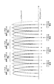
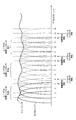
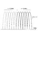
- FIG. 14 is a diagram illustrating a signal that reaches the receiving device from the transmitting device via the multipath environment.
- the horizontal axis represents time.
- the OFDM symbol is composed of an effective symbol and a guard interval obtained by copying and adding the latter half of the effective symbol before the effective symbol.
- the delay wave s2 When synchronizing with the preceding wave s1 (the wave that has arrived first) and performing the FFT process in the section t4, the delay wave s2 indicates that the delay time falls within the delay t1 within the guard interval, and the delay waves s3 and s4 Indicates a delayed wave having delays t2 and t3 exceeding the guard interval.
- the preceding wave and the delayed wave are also referred to as incoming waves.
- the hatched portion indicates the component of the OFDM symbol before the desired OFDM symbol.
- the delayed waves s3 and s4 as indicated by the hatched portion in front thereof, the OFDM symbol before the desired OFDM symbol is within the FFT interval of the desired OFDM symbol, and inter-symbol interference (ISI: Inter-Symbol Interference).
- Patent Document 1 One method for improving the characteristic deterioration due to the inter-symbol interference and inter-carrier interference is proposed in the following Patent Document 1.
- MAP Maximum A posteriori Probability: maximum posterior probability
- turbo equalization After creating a replica signal (interference replica signal) of an undesired subcarrier containing components, the signal removed from the received signal is subjected to signal equalization processing based on the MMSE (Minimum Mean Square Error) norm and demodulated again By repeating the process of performing the operation, the characteristic deterioration due to inter-symbol interference and inter-carrier interference is improved. In this way, a technique for repeatedly performing interference removal, equalization processing, and decoding processing while exchanging soft decision results is referred to as turbo equalization.
- MMSE Minimum Mean Square Error
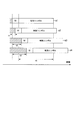
- FIG. 15 is an example of OFDMA in which two users are assigned to orthogonal subcarrier groups. Among the 12 subcarriers, user 1 occupies 6 subcarriers from the left, and user 2 occupies the remaining 6 subcarriers. In each subcarrier occupied by each user, a data modulation symbol transmitted by the user is arranged. Also in this OFDMA, if there is a delayed wave exceeding the guard interval, intersymbol interference and intercarrier interference occur, and the transmission characteristics of each user deteriorate.
- OFDMA Orthogonal Frequency Division Multiple Access
- the error correction decoding results of other users are required.
- the receiving apparatus of user 1 receives an OFDMA signal in which two users are orthogonally frequency-multiplexed as shown in FIG. 15, in order to generate an intersymbol interference replica, user 2 which is an undesired signal is used. It is necessary to generate a modulation symbol for user 2 from the decoding result.
- Control information necessary for the user 1 to perform demodulation processing and decoding processing of the user 2 such as MCS (Modulation and Coding Scheme) for the user 1 to perform the decoding processing and modulation symbol generation of the user 2 Need to know.
- MCS Modulation and Coding Scheme
- the user 1 and the user 2 cannot know the MCSs of other users, and therefore cannot sufficiently improve the characteristics. Also, when notifying other users' MCS and performing error correction decoding of other users, the use efficiency decreases due to an increase in the control signal.
- the present invention has been made in view of the above problems, and provides a receiving apparatus and a receiving method capable of improving transmission characteristics by removing inter-symbol interference and inter-subcarrier interference without increasing overhead such as control signals. There is to do.
- a receiving apparatus receives a signal multiplexed by a user using an orthogonal frequency, and suppresses a signal component of an undesired user from the received signal in a time domain. Perform filtering processing.
- the reception device receives a signal multiplexed by a user using an orthogonal frequency, and performs filtering processing in a time domain so as to suppress a signal component of an undesired user from the signal received by the reception unit
- a filtering unit that removes an interference component generated using a decoding processing result of the signal filtered by the filtering unit from the filtered signal and a signal output by the interference removing unit
- a signal detection unit that decodes the signal and outputs a decoding process result, and repeatedly performs the process by the interference removal unit and the process by the signal detection unit until a predetermined condition is satisfied, and the interference removal unit In the first iteration of the repetition, the filtered signal or the reception signal is generated without generating and removing the interference component. And outputs the received signals by parts, then generates an interference component using the previous decoding processing result.
- the reception apparatus further includes a control signal detection unit that detects a subcarrier position to which a data signal for a desired user is mapped from a control signal included in the signal received by the reception unit.
- the interference removal unit performs interference removal processing based on the subcarrier position.
- the filter unit sets a band for filtering processing based on the subcarrier position.
- the signal detection unit performs error correction decoding processing and outputs a soft decision value
- the interference removal unit generates an interference replica using the soft decision value output by the signal detection unit;
- a subtractor that subtracts the interference replica from the signal filtered by the filter.
- the reception method is configured to suppress a signal component of an undesired user from a first process of receiving a signal multiplexed by a user using an orthogonal frequency and the signal received through the first process.
- a second step of filtering in the time domain, and an interference component generated using a decoding result of the signal filtered by the second step is removed from the filtered signal and output.
- a communication system is a communication system including a transmission device that transmits a signal in which users are multiplexed using orthogonal frequencies, and a reception device that receives and decodes a signal transmitted by the transmission device,
- the receiving device includes: a receiving unit that receives the transmitted signal; a filter unit that performs filtering processing in a time domain so as to suppress a signal component of an undesired user from the signal received by the receiving unit; and the filter unit An interference removal unit that removes an interference component generated using the decoding processing result of the filtered signal from the filtered signal and outputs the signal, and a decoding process result obtained by decoding the signal output by the interference removal unit.
- a signal detection unit for outputting, and processing by the interference removal unit and processing by the signal detection unit are performed in a predetermined condition.
- the interference canceling unit outputs the filtered signal or the signal received by the receiving unit without generating and removing the interference component for the first time out of the repetitions, and then the previous time.
- An interference component is generated using the decoding processing result.
- the communication method is a communication method having a process of transmitting a signal multiplexed with users using orthogonal frequencies, and a process of receiving and decoding a signal transmitted by the transmitting process by a receiving apparatus.
- the receiving and decoding process includes a first process of receiving the transmitted signal and a filtering process in a time domain so as to suppress a signal component of an undesired user from the signal received by the first process.
- a second step of removing the interference component generated using the decoding processing result of the signal filtered in the second step from the filtered signal, and the third step A fourth process of decoding the signal output in the process of outputting the result of the decoding process and outputting the result of the decoding process, and the process of the third process and the process of the fourth process Processing is repeated until a predetermined condition is satisfied, and the third process is received by the filtered signal or the first process without generating and removing interference components for the first time in the repetition. Then, an interference component is generated using the previous decoding process result.
- FIG. 7 is a diagram illustrating an example in which a modulation symbol of user n input from a symbol generation unit 102-n is mapped to an input point of an IFFT unit 103.
- FIG. 7 is a diagram illustrating each subcarrier component of a signal output from the FFT unit 207.
- 3 is a schematic block diagram illustrating a configuration of an interference removal unit 205.
- FIG. 3 is a schematic block diagram illustrating a configuration of a replica generation unit 232.
- FIG. 6 is a flowchart illustrating an operation of receiving apparatus 200. It is a schematic block diagram which shows the structure of the transmitter 300 which concerns on the 2nd Embodiment of this invention. 6 is a diagram illustrating an example in which a modulation symbol and a control signal of a user n input from a symbol generation unit 102-n are mapped to an input point of an IFFT unit 303. FIG. It is a schematic block diagram which shows the structure of the receiver 400 which concerns on the 2nd Embodiment of this invention. It is a figure which shows the output signal of the FFT part 207 in case the process of the interference removal part 405 is an initial process.
- FIG. 10 is a flowchart illustrating an operation of receiving apparatus 400. It is a figure which shows the signal which reaches
- the transmission apparatus transmits an OFDMA signal, which is a signal in which users are multiplexed using orthogonal frequencies.
- a communication system includes a transmitting apparatus 100 that transmits an OFDMA signal in which a plurality of users are assigned to OFDM subcarriers, and a receiving apparatus 200 that receives a signal transmitted by the transmitting apparatus 100.
- the transmission device 100 is installed in a base station in the downlink of the mobile communication system, and the reception device is mounted on a mobile terminal in the downlink of the mobile communication system.
- the transmission device 100 is installed in a base station of a cellular system
- the reception device 200 is installed in one mobile terminal among a plurality of mobile terminals linked to the base station.
- FIG. 1 is a schematic block diagram showing the configuration of the transmission device 100 according to the first embodiment of the present invention.
- Transmitting apparatus 100 includes symbol generating sections 102-1 to 102-N, IFFT (Inverse Fast Fourier Transform) section 103, GI inserting section 104, transmitting section 105, and pilot generating section 106.
- Unit 101 is connected.
- N is the number of users that can be linked to the base station in which the transmission apparatus 100 is arranged.
- the symbol generation unit 102-n includes a coding unit 111-n, an interleaving unit 112-n, a modulation unit 113-n, and a serial / parallel conversion unit 114-n.
- the symbol generator 102-n includes a MAC (Media Access Control) unit or the like (not shown in FIG. 1).
- the MAC unit or the like refers to a function located in an upper layer such as a MAC layer or a network layer. A data signal to be transmitted to the user n input from.
- the data signal means a signal other than the control signal, and includes not only a data signal used for computer processing but also a compression-coded audio signal, video signal, and other information signals, and the same applies to the following.
- the encoding unit 111-n performs error correction encoding processing on the input data signal of the user n, which is one of turbo code, LDPC (Low Density Parity Check), convolutional code, and the like. .
- the interleaving unit 112-n arranges a sequence of encoded data signals of the user n output from the encoding unit 111-n in order to improve the occurrence of a burst error based on a drop in received power due to frequency selective fading. Change the order.
- the modulation unit 113-n performs BPSK (Binary Phase Shift Keying) and QPSK (Quadrature Phase Shift Keying) on the encoded data signal of the user n output from the interleaving unit 112-n.
- Modulation symbols are generated by performing data modulation such as four-phase phase shift keying), 16QAM (16 Quadrature Amplitude Modulation: 16-value quadrature amplitude modulation), 64QAM (64 Quadrature Amplitude Modulation).
- the serial / parallel conversion unit 114-n rearranges the modulation symbols of the user n output from the modulation unit 113-n from serial to parallel based on the input reference to the IFFT unit 103.
- Pilot generating section 106 generates pilot symbols that can estimate the propagation path in the receiving apparatus.
- the pilot symbol may be common to each mobile terminal (for each user) linked to the base station in which the transmission apparatus 100 is installed, or may be defined for each user.
- the code sequence constituting the pilot symbol is preferably an orthogonal sequence such as a Hadamard code or a CAZAC (Constant Amplitude Zero Auto-Correlation) sequence.
- the IFFT unit 103 maps the modulation symbol and pilot symbol of the user n input from the symbol generation unit 102-n to the IFFT input point based on the signal allocation information notified from the MAC unit or the like (not shown), By performing IFFT processing, each symbol is converted from a frequency domain signal to a time domain signal.
- FIG. 2 is a diagram illustrating an example in which the modulation symbol and pilot symbol of user n input from symbol generation section 102 -n are mapped to the input points of IFFT section 103.
- the mapping position and the number of mappings notified by the signal allocation information are the propagation path condition between the base station provided with the transmission apparatus 100 and each user's mobile terminal, the amount of data transmitted from the base station to each user's mobile terminal, and the like. To be determined. The determination of the mapping position and the number of mapping for each user is called scheduling.
- the signal allocation information may be notified to the mobile terminal using the same OFDM symbol and the same frame as the user, or may be different.
- the same number of subcarriers (number of IFFT input points) is assigned to each user, but it may be different for each user.
- subcarriers (IFFT input point positions) mapped to each user may be scattered without being adjacent to each other. Further, the subcarriers to which the pilot symbols are allocated may be different for each OFDM symbol and for each frame.
- user data signals and pilot signals are mapped to subcarriers constituting OFDMA, but control signals for each user may be included.
- the GI insertion unit 104 adds a guard interval (GI) to the time domain signal converted by the IFFT unit 103. For example, a part of the latter half of the time domain signal (effective symbol) output from the IFFT unit is copied and added to the head of the effective symbol. An effective symbol to which GI is added is called an OFDM symbol. If the signal output from the GI insertion unit 104 is s (t), it can be expressed by the following equation (1).
- N f is the number of IFFT points
- c k, l is a symbol assigned to the k-th subcarrier of the l-th OFDM symbol
- ⁇ f is a subcarrier interval
- T s is the OFDM symbol length (including the GI length).
- J is an imaginary unit.
- c k, l , c 0, l -c 2 l are assigned modulation symbols of user 1 (1 to 3 of IFFT input points shown in FIG. 2)
- c 4 , 1 to c 6 and l are assigned modulation symbols of user 2 (5 to 7 IFFT input points shown in FIG.
- the transmission unit 105 converts the OFDM symbol output from the GI insertion unit 104 into an analog signal (Digital-to-Analog conversion), performs a filtering process for band-limiting the signal converted into the analog signal, and further performs a filtering process
- the transmitted signal is converted into a transmittable frequency band and transmitted via the antenna unit 101.
- a signal output from the transmission apparatus 100 is referred to as an OFDMA signal.
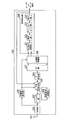
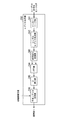
- FIG. 3 is a schematic block diagram showing the configuration of the receiving device 200 according to the first embodiment of the present invention.
- the reception apparatus 200 includes a reception unit 202, a filter unit 203, a reception signal storage unit 204, an interference removal unit 205, a GI removal unit 206, an FFT unit 207, a propagation path compensation unit 208, a signal detection unit 209, and a propagation path estimation unit 210.
- the antenna unit 201 is connected to the receiving unit 202.
- the receiving unit 202 when the receiving unit 202 receives the OFDMA signal transmitted from the transmitting apparatus 100 via the antenna unit 201, the receiving unit 202 down-converts the signal to a frequency band in which digital signal processing such as signal detection processing is possible, and further reduces spurious.
- a filtering process to be removed is performed, a conversion process for converting the filtered signal from an analog signal to a digital signal (Analog-to-Digital conversion) is performed, and the result is output to the filter unit 203 and the propagation path estimation unit 210.
- the propagation path estimation unit 210 performs propagation path estimation that estimates fluctuations in amplitude and phase due to fading or the like between the transmission apparatus 100 and the reception apparatus 200, and uses the propagation path estimation value that is the propagation path estimation result as the interference removal unit 205. And to the propagation path compensation unit 208.
- the propagation path estimation can be performed using, for example, pilot symbols that are known signals included in the signal output from the reception unit 202.
- pilot symbols that are known signals included in the signal output from the reception unit 202.
- the symbol-mapped OFDMA signal shown in FIG. 2 is received, it is a signal obtained by converting the received OFDMA signal into a frequency domain, and is a subcarrier signal (IFFT input points 4, 8, 12) to which pilot symbols are assigned. , 16 signal components) to calculate the frequency response.
- the frequency response of subcarriers other than the subcarrier in which the pilot symbol is arranged can be calculated by interpolation techniques such as linear interpolation and FFT interpolation using the frequency response of the subcarrier in which the pilot symbol is arranged.
- interpolation techniques such as linear interpolation and FFT interpolation using the frequency response of the subcarrier in which the pilot symbol is arranged.
- all pilot symbols arranged in the same OFDM symbol as the OFDM symbol in which the data signal of the desired user is arranged are used. It is possible to perform propagation path estimation.
- the propagation path estimation can be performed using only a part of pilot symbols arranged in the same OFDM symbol as the OFDM symbol in which the data signal of the desired user is arranged.
- the propagation path estimation can also use an OFDM symbol in which a data signal of a desired user is not arranged, or a pilot symbol arranged in a frame. Note that it is also possible to apply the propagation path estimation using the decoding result output from the signal detection unit 209 to the propagation path estimation.
- the filter unit 203 suppresses the signal component of the subcarrier in which the data signal of the undesired user is arranged from the signal output from the receiving unit 202 in the time domain. That is, a subcarrier including a desired data signal (data signal addressed to the receiving terminal) is extracted.
- filter section 203 is a time filter that suppresses frequency components of subcarriers in which data signals other than user 1 are arranged. That is, a subcarrier including a desired data signal (data signal addressed to a receiving terminal) is extracted by a time filter having a pass band corresponding to a frequency corresponding to subcarriers k of 1 to 3.
- an FIR filter Finite Impulse Response Filter
- an IIR filter Infinite Impulse Response filter
- a matched filter Melched Filter
- the receiving apparatus 200 is configured so that the position of the subcarrier in which the data signal is arranged is known before receiving the data signal of the desired user. For example, it is possible by receiving a notification from the transmission apparatus 100 before receiving the data signal by a control signal or the like.
- the reception signal storage unit 204 stores a signal output from the filter unit 203. In addition, when the interference removing unit 205 repeatedly performs interference processing, the stored signal is output.
- the interference cancellation unit 205 outputs the channel estimation value output from the channel compensation unit 210 and the soft decision value of the decoding result output from the signal detection unit 209, and is output from the filter unit 203 or the received signal storage unit 204.
- the process of removing the interference component from the signal is repeatedly performed. Specifically, using the log likelihood ratio LLR (Log Likelihood Ratio) of the encoded bits output from the signal detection unit 209, the transmission device 100 that is the transmission source of the received signal is addressed to the own reception device. Generate a signal replica that would have been sent. That is, the receiving apparatus 200 generates a transmission signal replica for the user 1 that the transmitting apparatus 100 would have transmitted. Further, an interference replica is generated using the transmission signal replica and the propagation path estimation value from the propagation path estimation unit 210, and is subtracted from the signal output from the filter unit 203 or the reception signal storage unit 204 (details will be described later).
- LLR Log Likelihood Ratio
- the GI removal unit 206 removes the guard interval section added by the transmission apparatus 100 in order to avoid distortion due to the delayed wave from the signal from which the interference component replica is output from the interference removal unit 205.
- the FFT unit 207 performs a Fourier transform process in which the signal from which the GI removal unit 206 has removed the guard interval section is converted from a time domain signal to a frequency domain signal.
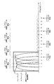
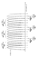
- FIG. 4 shows each subcarrier component of the signal output from the FFT unit 207.
- FIG. 4 shows a case where the transmission apparatus 100 performs the user assignment shown in FIG. 2, and output points 1 to 3 of the FFT unit 207 are subcarrier positions to which data addressed to the user 1 is assigned in the transmission apparatus 100.
- Output points 5 to 16 of FFT section 207 are subcarrier positions assigned to undesired users (addressed to users 2 to 4) or subcarrier positions assigned pilot symbols.
- the frequency component of the subcarrier component assigned to the undesired user of the FFT unit 207 or the subcarrier component assigned the pilot symbol is suppressed by the filter unit 203.
- the FFT unit 207 performs FFT processing. Furthermore, it is possible to reduce the inter-subcarrier interference that the subcarrier assigned to the desired user receives from the subcarrier component assigned to the undesired user.
- the band of the FFT output points 1 to 4 including the subcarrier position (FFT output point 4 of the FFT unit 207) to which the pilot symbol is allocated is set as the pass band of the filter unit 203, and a known pilot symbol is included.
- the interference removal unit 205 repeats the process to remove the interference that the subcarrier component at the FFT output point 4 gives to the subcarrier components (FFT output points 1 to 3) assigned to the desired user. .
- the filter unit 203 removes the interference that the subcarrier component of the FFT output point 4 gives to the subcarrier component assigned to the desired user.
- the propagation path compensator 208 uses the propagation path estimated value from the propagation path estimator 210 to correct the channel distortion due to fading using ZF (Zero Forcing), MMSE (Minimum Mean Square Error), and the like. And the weighting coefficient is multiplied by the frequency domain signal from the FFT unit 207 to perform propagation path compensation.
- the weighting factor preferably takes into account the frequency response of the filter unit 203 of the subcarrier in addition to the propagation path estimation value.
- the frequency response of the filter unit 203 is known to the receiving apparatus, and can be obtained by notifying the propagation path compensation unit 208.
- the signal detection unit 209 extracts a modulation symbol for a desired data signal from the signal output from the propagation path compensation unit 208, performs demodulation and decoding processing, and acquires a desired data signal. Also, the coded bit LLR for the desired data signal is output to the interference removal unit 205.
- the signal detection unit 209 includes a parallel / serial conversion unit 221, a demodulation unit 222, a deinterleave unit 223, and a decoding unit 224.
- the parallel-serial converter 221 extracts modulation symbols addressed to a desired user from the signals output from the propagation path compensator 208, and rearranges them from parallel to serial.
- Demodulation section 222 performs demodulation processing on the modulation symbol output from parallel to serial conversion section 221 and outputs a soft decision value (encoded bit LLR).
- ⁇ is an equivalent amplitude after propagation path compensation.
- the propagation path estimation value in the k-th subcarrier is H (k) and the multiplied MMSE-based propagation path compensation weight is W (k)
- ⁇ is W ( k) ⁇ H (k).
- ⁇ (b 1 ) is obtained by replacing the real part and the imaginary part of Xc in the equation (3), that is, the equation for obtaining ⁇ (b 0 ). It should be noted that it is possible to calculate based on the same principle for data subjected to other modulation such as 16QAM.
- the demodulator 222 may calculate a hard decision result instead of a soft decision result.
- the deinterleaving unit 223 rearranges the bit arrangement corresponding to the interleaving pattern performed by the interleaving unit 112-n of the transmission apparatus 100 that is the transmission source, that is, performs the bit arrangement rearranging that is the reverse operation of the interleaving pattern. This is performed on the data series of the soft decision result by 222.
- the decoding unit 224 performs error correction decoding processing for error correction coding such as turbo coding and convolution coding performed by the transmission apparatus 100 as a transmission source on the output signal from the deinterleaving unit 223, and performs coding bits
- the soft decision output result such as LLR (log likelihood ratio) is calculated, and the soft decision result of the desired user is input to the interference removal unit 205.
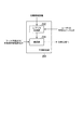
- FIG. 5 is a schematic block diagram showing the configuration of the interference removal unit 205.
- the interference removal unit 205 includes a subtraction unit 231 and a replica generation unit 232.
- the replica generation unit 232 generates a replica of the interference component (interference replica) by using the propagation path estimation value and the soft decision value (log likelihood ratio LLR of the encoded bit) for the data signal of the desired user. Specifically, using the log likelihood ratio LLR of the encoded bits after decoding output from the signal detection unit 209, the transmission device 100 that is the transmission source of the received signal would have transmitted to the own reception device. Generate a signal replica. That is, the receiving apparatus 200 generates a transmission signal replica for the user 1 that the transmitting apparatus 100 would have transmitted.
- an interference replica is generated using the transmission signal replica and the propagation path estimation value from the propagation path estimation unit 210.
- the subtracting unit 231 subtracts the interference replica from the signal input from the filter unit 203 or the received signal storage unit 204. Assuming that the signal input from the filter unit 203 or the received signal storage unit 204 is r (t) and the interference replica in the i-th iterative processing is r ⁇ i (t), the signals r 1 to i (t ) Can be expressed by the following equation (4).
- FIG. 6 is a schematic block diagram showing the configuration of the replica generation unit 232.
- the replica generation unit 232 includes an interleaving unit 241, a symbol replica generation unit 242, a serial / parallel conversion unit 243, an IFFT unit 244, a GI insertion unit 245, and an interference replica generation unit 246.
- Interleaving section 241 rearranges the log likelihood ratio LLR of the encoded bits output from signal detection section 209 in the same order as the encoded data signal subjected to data modulation by transmitting apparatus 100. That is, the log likelihood ratio LLR of the encoded bits output from the signal detection unit 209 is interleaved with the same interleaving pattern as the interleaving unit 112-1 of the transmission apparatus 100. That is, the reverse sorting is performed in the deinterleaving unit 223 included in the signal detection unit 209.
- the symbol replica generation unit 242 generates a modulation symbol replica (modulation symbol replica) for the signal of the desired user using the log likelihood ratio LLR of the encoded bits output from the interleaving unit 241. For example, when the modulation scheme of the modulation unit 113-1 of the transmission apparatus 100 is QPSK modulation, the symbol replica generation unit 242 sets the log likelihood ratio of the bits b 0 and b 1 constituting the QPSK modulation symbol to ⁇ (b 0 ). , ⁇ (b 1 ), a replica symbol of a QPSK modulation symbol expressed by the following equation (5) is generated. Note that the symbol replica generation unit 242 generates a modulation symbol replica based on the same principle in the case of other modulation such as 16QAM.
- the serial-to-parallel converter 243 rearranges the modulation symbol replica output from the symbol replica generator 242 from serial to parallel based on the subcarrier position and the number of subcarriers where the modulation symbol of the user 1 is arranged on the transmission side.
- the IFFT unit 244 corresponds to the modulation symbol replica output from the serial / parallel conversion unit 243 to the subcarrier position to which the modulation symbol (modulation symbol of the user 1) corresponding to the modulation symbol replica is assigned in the received OFDMA signal.
- a modulation symbol replica of the desired user (a modulation symbol replica of the desired user) is converted from a frequency domain signal to a time domain signal.
- the subcarrier position where the modulation symbol of the undesired user is arranged in the received OFDMA signal is set to null (zero is arranged).
- IFFT section 244 preferably arranges the pilot symbol at the IFFT input point corresponding to the subcarrier position where the pilot symbol which is a known signal has been arranged. For example, when the received OFDMA signal is assigned with the modulation symbol of each user in the user assignment of FIG. 2, the modulation symbol replica output by the symbol replica generation unit 242 is assigned to IFFT input points 1 to 3. A pilot symbol is assigned to 4 of the IFFT input points.
- the GI insertion unit 245 adds a guard interval (GI) to the time domain signal converted by the IFFT unit 244.
- GI guard interval
- the signal replica s i (t) output from the GI insertion unit 245 can be expressed by the following equation (6).
- c ⁇ k, l is a modulation symbol of a desired user.
- c ⁇ k, l is a symbol assigned to a subcarrier in the pass band of the filter unit 203, and may include a known symbol such as a pilot symbol.
- modulation symbols c 0,1 to c 2, l and pilot symbols c 3, l of user 1 are allocated to the corresponding subcarrier positions.
- Interference replica generation section 246 generates an interference replica of the interference component received by the OFDMA signal received by receiving apparatus 200, using the signal output from GI insertion section 245 and the propagation path estimation value.
- Interference components include intersymbol interference and intercarrier interference, and an interference replica is generated for each interference component.
- the signal output from the GI insertion unit 245 in the i-th iterative process of the interference removal unit 205 is represented by s i (t)
- the propagation path estimation value is represented by h ( t)
- the inter-symbol interference replica r i (t) (t ⁇ T s , where T s is the OFDM symbol length) generated by the interference replica generation unit 246 is expressed by Equation (7).
- the interference replica r i is generated by using the transmission replica for the desired user generated from ⁇ i ⁇ 1 that is the encoded bit LLR output from the signal detection unit 209 in the i ⁇ 1th iteration processing, In each delayed wave having a delay time exceeding the GI received by the apparatus, it is an OFDM symbol before the OFDM symbol subjected to FFT processing, and is a sum of replicas of components that have entered the OFDM symbol interval subjected to FFT processing. is there.
- intersymbol interference is removed. Note that the control signal for the desired user and intersymbol interference to the pilot symbol can be similarly removed.
- h d is the impulse response of the channel estimation value
- the complex amplitude of the d-th path t is time
- ⁇ d is a delay time from the time when the first path (preceding wave) of the d-th path (d-th delayed wave) arrives (synchronization point of FFT processing)
- T gi is the guard interval length inserted. It is assumed that d satisfies ⁇ d > T gi .
- the generation of the interference replica preferably takes into account the impulse response of the filter unit 203 in addition to the propagation path estimation value.
- the impulse response of the filter unit 203 is known to the receiving device, and can be obtained by notifying the replica generation unit 232. That is, the inter-symbol interference replica r ⁇ i ′ (t) generated by the interference replica generation unit 246 is expressed by Expression (8).
- g (t) is the impulse response of the filter section
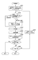
- FIG. 7 is a flowchart for explaining the operation of the receiving apparatus 200.
- Receiving apparatus 200 receives the OFDMA signal transmitted from transmitting apparatus 100, filter section 203 filters the frequency component in which the data signal of the undesired user is arranged, and arranges the data signal of the desired user. Only existing frequency components are extracted (S101).
- interference cancellation for the signal of the desired user is performed using an interference replica generated from the coded bit LLR calculated by the decoding process in the (i-1) th iterative process (S103). ).
- FFT processing is performed in the FFT unit 207 on the signal subjected to the processing of S102 and S103 (S104), and propagation path distortion compensation is performed in the propagation path compensation unit 208 on the signal converted into the frequency domain. It performs (S105).
- demodulation processing and decoding processing are performed (S106), and a predetermined number of repetitions is completed in interference removal processing (YES in S107) , The process is terminated and reception of the next data is awaited.
- the transmitting apparatus 100 transmits an OFDMA signal and the receiving apparatus 200 receives the OFDMA signal with a long delay exceeding the guard interval
- the receiving apparatus 200 responds to an undesired user signal.
- the frequency component to which the undesired user is assigned is reduced by a time filter. Therefore, since signal components of undesired users can be reduced, intersymbol interference and intercarrier interference due to components of undesired users caused by FFT processing can be suppressed.
- the signal component of the undesired user can be suppressed by the time filter, and it is possible to apply the repeated interference removal that removes the interference component using the interference replica generated from the soft decision result obtained by the decoding process to the desired user.
- Intersymbol interference and intercarrier interference for a desired user can be suppressed with high accuracy. That is, it is possible to apply iterative interference removal that can remove interference with high accuracy with respect to a desired user without calculating a soft decision value for the undesired user by reducing the signal component of the undesired user with a time filter. Thus, even when an OFDMA signal in which a plurality of users are multiple-connected is received in a propagation path environment in which a long delay exceeding the guard interval occurs, it is possible to obtain good reception characteristics.
- the communication system includes a transmitting apparatus 300 that transmits an OFDMA signal in which a plurality of users are assigned to OFDM subcarriers, and a receiving apparatus 400 that receives a signal transmitted by the transmitting apparatus 300. Consists of Hereinafter, a case will be described where the transmission apparatus 300 is installed in a base station of a cellular system and the reception apparatus 400 is installed in one mobile terminal among a plurality of mobile terminals linked to the base station.
- FIG. 8 is a schematic block diagram showing the configuration of the transmission apparatus 300 according to the second embodiment of the present invention.
- Transmitting apparatus 300 includes symbol generating sections 102-1 to 102-N, IFFT section 303, GI inserting section 104, transmitting section 105, pilot generating section 106, and control signal generating section 306.
- An antenna unit 101 is connected.
- N is the number of users that can be linked to the base station in which the transmission apparatus 100 is arranged.
- Components having functions equivalent to those of the transmission device 100 of the first embodiment are given the same reference numerals. In the following, components having functions different from those of the transmission device 100 will be mainly described.
- the control signal generator 306 generates a control signal for each user's data signal generated by the symbol generators 102-1 to 102-N and inputs the control signal to the IFFT unit 303.
- Control signals include data modulation methods, coding rates, transmission signal notifications such as MIMO (Multiple Input Multiple Multiple Output) ranks, transmission signal format information such as pilot arrangement positions, and data signals such as synchronization signals. This signal is necessary for detection.
- the control signal is preferably subjected to error correction coding and data modulation.
- IFFT section 303 is a modulation symbol of each user's data signal input from symbol generation sections 102-1 to 102-N, a pilot symbol input from pilot generation section 106, and a control input from control signal generation section 306.
- the signal is mapped to the input point of IFFT section 303 based on the signal allocation information.
- the signal allocation information is information related to subcarrier positions to which data signals, pilot symbols, and control signals for each user are allocated.
- FIG. 9 is a diagram illustrating an example in which the modulation symbol, pilot symbol, and control signal of user n input from symbol generation section 102 -n are mapped to the input points of IFFT section 303.
- pilot symbols and control signals are mapped so as to be scattered on subcarriers, but may be mapped to predetermined subcarrier positions.
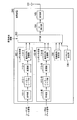
- the reception apparatus 400 includes a reception unit 202, a filter unit 403, a reception signal storage unit 404, an interference removal unit 405, a GI removal unit 206, an FFT unit 207, a propagation path compensation unit 208, a signal detection unit 409, a control signal detection unit 411, A propagation path estimation unit 210 is provided, and an antenna unit 201 is connected to the reception unit 202.
- Components having functions equivalent to those of the receiving apparatus 200 of the first embodiment are given the same reference numerals. In the following, components having functions different from those of the receiving apparatus 200 will be mainly described.
- the reception signal storage unit 404 stores the output signal from the reception unit 202. Further, when the interference removal unit 405 repeatedly performs interference removal processing, the stored signal is input to the filter unit 403.
- the filter unit 403 receives the signal of the desired user based on the subcarrier position information in which the signal of the desired user input from the control signal detection unit 411 is arranged with respect to the signal input from the received signal storage unit 404.
- the frequency band and the bandwidth are made variable so that the frequency component of the arranged subcarrier becomes the pass band.
- the control signal detection unit 411 extracts a symbol to which the control signal is mapped from signals output from the FFT unit 207 and whose propagation path distortion is compensated by the propagation path compensation unit 208. Further, demodulation and decoding processes are performed on the extracted symbols to obtain control information. In addition, the control signal detection unit 411 notifies the filter unit 403 of the acquired control information and the subcarrier position to which the data of the desired user is mapped. Further, the signal detection unit 409 is notified of information on the modulation method and coding rate of the data signal of the desired user. In the control signal detection unit 411, the function of performing the process using the channel estimation value such as channel distortion compensation can use the channel estimation value calculated by the channel estimation unit 210.
- control signal detection unit 411 performs the above-described processing on the signal whose band is limited by the filter unit 203 including the subcarrier position in the passband. Thus, the control signal can be acquired.
- the signal detection unit 409 performs signal detection processing based on information on the modulation method and coding rate of the data signal of the desired user input from the control signal detection unit 411.
- the signal detection unit 409 includes a parallel / serial conversion unit 221, a demodulation unit 422, a deinterleave unit 223, and a decoding unit 424.
- the demodulator 422 performs demodulation processing based on the information on the modulation method of the data signal of the desired user input from the control signal detector 411, and outputs a soft decision value (encoded bit LLR).
- the decoding unit 424 performs an error correction decoding process corresponding to the error correction coding based on the information regarding the coding rate of the desired user input from the control signal detection unit 411, and obtains a soft decision value (coded bit LLR). Output to the interference removal unit 405.
- FIG. 11 is a diagram illustrating an output signal of the FFT unit 207 when the process of the interference removing unit 405 is the initial process.
- the signal from the receiving unit 202 is input to the interference removing unit 405, and the signal components of all subcarriers, that is, the signal components mapped to each subcarrier in the transmission apparatus 300 are output.
- the control signal detection unit 411 acquires information necessary for detecting the data signal of the desired user such as the subcarrier position, modulation and coding scheme assigned to the desired user from the control signal of FIG.
- FIG. 12 is a diagram illustrating an output signal of the FFT unit 207 when the process of the interference removing unit 405 is an iterative process.
- the signal extracted based on the subcarrier position information assigned to the desired user by the filter unit 403 is subjected to FFT processing, so that the frequency components of the subcarriers assigned to the undesired user are suppressed. Therefore, even when the control information related to the desired data is transmitted in the same OFDM symbol or the same time slot as the desired data, information on the position where the desired data is mapped is acquired from the control information, and the frequency component of the undesired user is obtained. Then, it is possible to repeatedly remove interference for a desired user.
- FIG. 12 is a diagram illustrating an output signal of the FFT unit 207 when the process of the interference removing unit 405 is an iterative process.
- the signal extracted based on the subcarrier position information assigned to the desired user by the filter unit 403 is subjected to FFT processing, so that the frequency components of the sub
- the frequency component of the subcarrier to which the data of the undesired user is allocated, the frequency component of the subcarrier to which the pilot symbol is arranged, and the frequency component of the subcarrier to which the control signal is arranged may be set so as to suppress only the frequency component of the subcarrier to which the data of the undesired user is allocated.
- the receiving apparatus repeatedly performs interference cancellation only on the data signal of the desired user.
- a signal that can be decoded by the receiving apparatus such as a control signal related to the data signal of the desired user. As described above, it is possible to apply the above-described repeated interference cancellation.
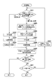
- FIG. 13 is a flowchart for explaining the operation of the receiving apparatus 400.
- the signal output from the unit 202 is subjected to FFT processing in the FFT unit 207 after processing in the GI removal unit 206 (S402), and the propagation path compensation unit 208 performs propagation path processing on the signal converted into the frequency domain. Distortion compensation is performed (S403).
- control signal detection unit 411 extracts a control signal from the frequency domain signal subjected to propagation path compensation, the subcarrier position where the desired user data is mapped, the modulation method of the desired user data signal, the code Information on the conversion rate is acquired (S404).
- the signal detection unit 409 performs demodulation and decoding processing based on the information regarding the modulation method and coding rate of the desired user data signal, and calculates the coded bit LLR for the desired user data signal (S409).
- the interference cancellation is an iterative process (i> 0) in S401
- the output signal of the reception unit 202 stored in the reception signal storage unit 404 is input to the filter unit 403 and acquired by the control signal detection unit 411.
- the interference removal unit 405 uses the interference replica generated from the coded bit LLR calculated by the decoding process in the i-1th iteration process for the signal output from the filter unit 403, and uses the interference replica generated by the desired user. Interference removal for the signal is performed (S406).
- the signal subjected to interference removal processing by the interference removal unit 405 is subjected to FFT processing in the FFT unit 207 after processing in the GI removal unit 206 (S407), and the propagation path compensation unit 208 performs propagation path processing on the signal converted into the frequency domain.
- the signal detection unit 409 After compensating for distortion (S408), the signal detection unit 409 performs demodulation and decoding processing based on information on the modulation method and coding rate of the desired user's data signal and performs coding bits on the desired user's data signal. LLR is calculated (S409).
- the transmitting apparatus 300 transmits an OFDMA signal and the receiving apparatus 400 receives the OFDMA signal with a long delay exceeding the guard interval
- the receiving apparatus 400 responds to an undesired user signal.
- the frequency component to which the undesired user is assigned is reduced by a time filter. Therefore, since signal components of undesired users can be reduced, intersymbol interference and intercarrier interference due to components of undesired users caused by FFT processing can be suppressed.
- the signal component of the undesired user can be suppressed by the time filter, and it is possible to apply the repeated interference removal that removes the interference component using the interference replica generated from the soft decision result obtained by the decoding process to the desired user.
- Intersymbol interference and intercarrier interference for a desired user can be suppressed with high accuracy. Furthermore, in the receiving apparatus 400 according to the present embodiment, a time filter that suppresses the signal component of the undesired user is applied only in the iterative process, so that the control signal for the data signal of the desired user is transmitted in the same time slot as the data signal. Even in such a case, the signal detection of the data signal of the desired user can be performed. Further, since the time filter band is set based on the control signal, even when the control signal for the data signal is transmitted in the same time slot as the data signal, it is possible to repeatedly perform interference cancellation processing for a desired user. Can be applied.
- the present invention is applied to OFDMA that assigns signals of a plurality of users to OFDM subcarriers.
- Users are multiplexed using orthogonal frequency such as CDMA (Multi Carrier-Code Division Multiple Access), SC-FDMA (Single Carrier-Frequency Division Multiple Access), DFT-S-OFDMA (Discrete Fourier Transform-Spread-OFDMA).
- CDMA Multi Carrier-Code Division Multiple Access
- SC-FDMA Single Carrier-Frequency Division Multiple Access
- DFT-S-OFDMA Discrete Fourier Transform-Spread-OFDMA
- the present invention can be applied to a communication system that transmits a transmitted signal.
- the present invention can be used in the field of multi-carrier wireless communication.
Landscapes
- Engineering & Computer Science (AREA)
- Computer Networks & Wireless Communication (AREA)
- Signal Processing (AREA)
- Power Engineering (AREA)
- Physics & Mathematics (AREA)
- Probability & Statistics with Applications (AREA)
- Noise Elimination (AREA)
Priority Applications (1)
| Application Number | Priority Date | Filing Date | Title |
|---|---|---|---|
| US13/322,034 US20120063532A1 (en) | 2009-05-28 | 2010-04-15 | Reception device, receiving method, communication system, and communication method |
Applications Claiming Priority (2)
| Application Number | Priority Date | Filing Date | Title |
|---|---|---|---|
| JP2009-128748 | 2009-05-28 | ||
| JP2009128748A JP2010278722A (ja) | 2009-05-28 | 2009-05-28 | 受信装置、受信方法、通信システムおよび通信方法 |
Publications (1)
| Publication Number | Publication Date |
|---|---|
| WO2010137231A1 true WO2010137231A1 (ja) | 2010-12-02 |
Family
ID=43222363
Family Applications (1)
| Application Number | Title | Priority Date | Filing Date |
|---|---|---|---|
| PCT/JP2010/002754 Ceased WO2010137231A1 (ja) | 2009-05-28 | 2010-04-15 | 受信装置、受信方法、通信システムおよび通信方法 |
Country Status (3)
| Country | Link |
|---|---|
| US (1) | US20120063532A1 (enExample) |
| JP (1) | JP2010278722A (enExample) |
| WO (1) | WO2010137231A1 (enExample) |
Cited By (1)
| Publication number | Priority date | Publication date | Assignee | Title |
|---|---|---|---|---|
| WO2014176774A1 (en) * | 2013-05-02 | 2014-11-06 | Harman International Industries, Incorporated | Transformation between time domain and frequency domain based on nearly orthogonal filter banks |
Families Citing this family (12)
| Publication number | Priority date | Publication date | Assignee | Title |
|---|---|---|---|---|
| US8792789B1 (en) * | 2012-03-07 | 2014-07-29 | Applied Micro Circuits Corporation | Optimized chromatic dispersion filter |
| US8909061B1 (en) * | 2012-03-07 | 2014-12-09 | Applied Micro Circuits Corporation | Chromatic dispersion pre-compensation |
| JP5896461B2 (ja) * | 2012-03-19 | 2016-03-30 | 日本電気株式会社 | 信号分離装置、信号分離方法 |
| CN104365044B (zh) * | 2012-06-14 | 2017-10-17 | 瑞典爱立信有限公司 | 无线网络中的干扰消除 |
| JP2015053668A (ja) * | 2013-08-08 | 2015-03-19 | 株式会社Nttドコモ | ユーザ装置、基地局、逐次干渉キャンセル処理方法、及び逐次干渉キャンセル制御方法 |
| US9621391B2 (en) * | 2013-09-24 | 2017-04-11 | Huawei Technologies Co., Ltd. | Methods and apparatuses to improve reception of direct detection optical signals |
| CN104660319B (zh) * | 2013-11-18 | 2019-02-05 | 深圳市中兴微电子技术有限公司 | 一种干扰消除方法及装置 |
| JP2015207816A (ja) * | 2014-04-17 | 2015-11-19 | 富士通株式会社 | 受信装置、受信方法、及び、無線通信システム |
| KR20160048360A (ko) * | 2014-10-24 | 2016-05-04 | 삼성전자주식회사 | 이동 통신 시스템에서 간섭 측정에 기반한 신호 수신 방법 및 장치 |
| US10097255B2 (en) * | 2015-07-01 | 2018-10-09 | Qualcomm Incorporated | Joint channel and phase noise estimation in control symbols of a millimeter wave link |
| US20200045712A1 (en) * | 2016-11-01 | 2020-02-06 | Nec Corporation | Base station, terminal apparatus, method, program, and recording medium |
| US10312953B2 (en) * | 2016-12-26 | 2019-06-04 | Industrial Technology Research Institute | Orthogonal frequency division multiplexing receiver with low-resolution analog to digital converter and electronic device thereof |
Citations (2)
| Publication number | Priority date | Publication date | Assignee | Title |
|---|---|---|---|---|
| JP2008160576A (ja) * | 2006-12-25 | 2008-07-10 | Toshiba Corp | 基地局、端末および信号送信方法 |
| JP2008278338A (ja) * | 2007-05-01 | 2008-11-13 | Matsushita Electric Ind Co Ltd | Mimo受信装置 |
Family Cites Families (3)
| Publication number | Priority date | Publication date | Assignee | Title |
|---|---|---|---|---|
| US7701917B2 (en) * | 2004-02-05 | 2010-04-20 | Qualcomm Incorporated | Channel estimation for a wireless communication system with multiple parallel data streams |
| US7688708B2 (en) * | 2006-03-24 | 2010-03-30 | Alcatel-Lucent Usa Inc. | Method of OFDMA tone interference cancellation |
| JP2008283296A (ja) * | 2007-05-08 | 2008-11-20 | Toshiba Corp | 受信装置と受信方法 |
-
2009
- 2009-05-28 JP JP2009128748A patent/JP2010278722A/ja active Pending
-
2010
- 2010-04-15 US US13/322,034 patent/US20120063532A1/en not_active Abandoned
- 2010-04-15 WO PCT/JP2010/002754 patent/WO2010137231A1/ja not_active Ceased
Patent Citations (2)
| Publication number | Priority date | Publication date | Assignee | Title |
|---|---|---|---|---|
| JP2008160576A (ja) * | 2006-12-25 | 2008-07-10 | Toshiba Corp | 基地局、端末および信号送信方法 |
| JP2008278338A (ja) * | 2007-05-01 | 2008-11-13 | Matsushita Electric Ind Co Ltd | Mimo受信装置 |
Non-Patent Citations (1)
| Title |
|---|
| KATSUYA KATO ET AL.: "Amplify-and-Forward Relay Denso ni Okeru Multi Path Bunkatsu SC/MMSE Turbo Toka no Kento", IEICE TECHNICAL REPORT, RCS2009-7, THE INSTITUTE OF ELECTRONICS, INFORMATION AND COMMUNICATION ENGINEERS, 14 May 2009 (2009-05-14), pages 37 - 42 * |
Cited By (2)
| Publication number | Priority date | Publication date | Assignee | Title |
|---|---|---|---|---|
| WO2014176774A1 (en) * | 2013-05-02 | 2014-11-06 | Harman International Industries, Incorporated | Transformation between time domain and frequency domain based on nearly orthogonal filter banks |
| US9871685B2 (en) | 2013-05-02 | 2018-01-16 | Harman International Industries, Incorporated | Transformation between time domain and frequency domain based on nearly orthogonal filter banks |
Also Published As
| Publication number | Publication date |
|---|---|
| JP2010278722A (ja) | 2010-12-09 |
| US20120063532A1 (en) | 2012-03-15 |
Similar Documents
| Publication | Publication Date | Title |
|---|---|---|
| WO2010137231A1 (ja) | 受信装置、受信方法、通信システムおよび通信方法 | |
| KR100956042B1 (ko) | 무선 통신 시스템에서의 제한된 호핑 | |
| US8995540B2 (en) | Radio communication system and transmitting apparatus used for the same | |
| JP5237214B2 (ja) | 送信装置、受信装置、または無線通信の処理方法 | |
| CN101326740A (zh) | 发送正交频分复用信号的方法及其发射机和接收机 | |
| JP2004221702A (ja) | Ofdm(直交周波数分割多重)適応等化受信方式及び受信機 | |
| JP5254180B2 (ja) | 受信装置、受信方法、通信システムおよび通信方法 | |
| WO2010143532A1 (ja) | 受信装置及び受信方法 | |
| JP2007538477A (ja) | Ofdmシステムのためのスロットからインターレースおよびインターレースからスロットへの変換器 | |
| EP1211836A1 (en) | Communication device and communication method | |
| WO2011058798A1 (ja) | 受信装置、受信方法、及び受信プログラム | |
| JP5030311B2 (ja) | 受信機、受信方法および集積回路 | |
| JP2010028762A (ja) | 通信装置、通信システムおよび受信方法 | |
| KR101001730B1 (ko) | 와이브로 시스템에서 ici 제거에 적합한 반복 수신기장치 및 그 방법 | |
| US20070133393A1 (en) | Multi-carrier receiving method and multi-carrier receiving apparatus | |
| JP5254526B2 (ja) | 伝送性能を向上させるためのシステム、モデム、受信器、送信器及びその方法 | |
| JP2012060407A (ja) | 受信装置、通信システム、受信装置の制御プログラムおよび集積回路 | |
| JP2010178273A (ja) | 受信装置及び受信方法 | |
| JP2010199729A (ja) | 通信システム、通信方法、受信装置および受信方法 | |
| CN101208874A (zh) | 采用频分复用的通信系统的导频传送和信道估计 | |
| JP2007074224A (ja) | マルチキャリア伝送システム及びマルチキャリア伝送方法 | |
| JP5178320B2 (ja) | 無線通信システム、通信装置、無線通信方法、無線通信プログラム、及びプロセッサ | |
| JP2010161647A (ja) | 送信装置、通信システム、送信方法、及び、受信装置 | |
| JP2009016924A (ja) | Ofdm信号の送信方法、ofdm送信機及びofdm受信機 | |
| JP5252734B2 (ja) | 無線受信装置、無線受信方法、及び無線受信プログラム |
Legal Events
| Date | Code | Title | Description |
|---|---|---|---|
| 121 | Ep: the epo has been informed by wipo that ep was designated in this application |
Ref document number: 10780193 Country of ref document: EP Kind code of ref document: A1 |
|
| WWE | Wipo information: entry into national phase |
Ref document number: 13322034 Country of ref document: US |
|
| NENP | Non-entry into the national phase |
Ref country code: DE |
|
| 122 | Ep: pct application non-entry in european phase |
Ref document number: 10780193 Country of ref document: EP Kind code of ref document: A1 |