WO2010134381A1 - Dispositif radar - Google Patents
Dispositif radar Download PDFInfo
- Publication number
- WO2010134381A1 WO2010134381A1 PCT/JP2010/054839 JP2010054839W WO2010134381A1 WO 2010134381 A1 WO2010134381 A1 WO 2010134381A1 JP 2010054839 W JP2010054839 W JP 2010054839W WO 2010134381 A1 WO2010134381 A1 WO 2010134381A1
- Authority
- WO
- WIPO (PCT)
- Prior art keywords
- sweep
- signal
- calculated
- radar apparatus
- beat frequency
- Prior art date
Links
Images
Classifications
-
- G—PHYSICS
- G01—MEASURING; TESTING
- G01S—RADIO DIRECTION-FINDING; RADIO NAVIGATION; DETERMINING DISTANCE OR VELOCITY BY USE OF RADIO WAVES; LOCATING OR PRESENCE-DETECTING BY USE OF THE REFLECTION OR RERADIATION OF RADIO WAVES; ANALOGOUS ARRANGEMENTS USING OTHER WAVES
- G01S13/00—Systems using the reflection or reradiation of radio waves, e.g. radar systems; Analogous systems using reflection or reradiation of waves whose nature or wavelength is irrelevant or unspecified
- G01S13/02—Systems using reflection of radio waves, e.g. primary radar systems; Analogous systems
- G01S13/50—Systems of measurement based on relative movement of target
- G01S13/58—Velocity or trajectory determination systems; Sense-of-movement determination systems
- G01S13/583—Velocity or trajectory determination systems; Sense-of-movement determination systems using transmission of continuous unmodulated waves, amplitude-, frequency-, or phase-modulated waves and based upon the Doppler effect resulting from movement of targets
- G01S13/584—Velocity or trajectory determination systems; Sense-of-movement determination systems using transmission of continuous unmodulated waves, amplitude-, frequency-, or phase-modulated waves and based upon the Doppler effect resulting from movement of targets adapted for simultaneous range and velocity measurements
-
- G—PHYSICS
- G01—MEASURING; TESTING
- G01S—RADIO DIRECTION-FINDING; RADIO NAVIGATION; DETERMINING DISTANCE OR VELOCITY BY USE OF RADIO WAVES; LOCATING OR PRESENCE-DETECTING BY USE OF THE REFLECTION OR RERADIATION OF RADIO WAVES; ANALOGOUS ARRANGEMENTS USING OTHER WAVES
- G01S13/00—Systems using the reflection or reradiation of radio waves, e.g. radar systems; Analogous systems using reflection or reradiation of waves whose nature or wavelength is irrelevant or unspecified
- G01S13/02—Systems using reflection of radio waves, e.g. primary radar systems; Analogous systems
- G01S13/06—Systems determining position data of a target
- G01S13/42—Simultaneous measurement of distance and other co-ordinates
- G01S13/44—Monopulse radar, i.e. simultaneous lobing
-
- G—PHYSICS
- G01—MEASURING; TESTING
- G01S—RADIO DIRECTION-FINDING; RADIO NAVIGATION; DETERMINING DISTANCE OR VELOCITY BY USE OF RADIO WAVES; LOCATING OR PRESENCE-DETECTING BY USE OF THE REFLECTION OR RERADIATION OF RADIO WAVES; ANALOGOUS ARRANGEMENTS USING OTHER WAVES
- G01S13/00—Systems using the reflection or reradiation of radio waves, e.g. radar systems; Analogous systems using reflection or reradiation of waves whose nature or wavelength is irrelevant or unspecified
- G01S13/02—Systems using reflection of radio waves, e.g. primary radar systems; Analogous systems
- G01S2013/0236—Special technical features
- G01S2013/0245—Radar with phased array antenna
- G01S2013/0263—Passive array antenna
-
- G—PHYSICS
- G01—MEASURING; TESTING
- G01S—RADIO DIRECTION-FINDING; RADIO NAVIGATION; DETERMINING DISTANCE OR VELOCITY BY USE OF RADIO WAVES; LOCATING OR PRESENCE-DETECTING BY USE OF THE REFLECTION OR RERADIATION OF RADIO WAVES; ANALOGOUS ARRANGEMENTS USING OTHER WAVES
- G01S3/00—Direction-finders for determining the direction from which infrasonic, sonic, ultrasonic, or electromagnetic waves, or particle emission, not having a directional significance, are being received
- G01S3/02—Direction-finders for determining the direction from which infrasonic, sonic, ultrasonic, or electromagnetic waves, or particle emission, not having a directional significance, are being received using radio waves
- G01S3/74—Multi-channel systems specially adapted for direction-finding, i.e. having a single antenna system capable of giving simultaneous indications of the directions of different signals
Definitions
- the present invention relates to a radar apparatus that observes the distance and speed of a vehicle by an FMCW (Frequency-Modulated-Continuous Wave) method.
- FMCW Frequency-Modulated-Continuous Wave
- the FMCW method is known as a simple radar method for observing a vehicle traveling on a road with a radar device (for example, see Non-Patent Document 1).
- a radar apparatus employing this FMCW method the distance and speed are unknown.
- two parameters are generally calculated simultaneously by combining up-chirp and down-chirp.
- the beat frequency is close to a direct current (frequency is 0) component at a short distance
- the beat frequency is separated from the direct current even at a short distance by increasing the frequency gradient (frequency band B / sweep time T). Need to be frequency.
- the frequency band B and the sample frequency PRF are limited, there is a problem that the integral number N cannot be increased.
- the SN ratio signal / noise ratio
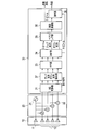
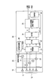
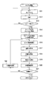
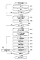
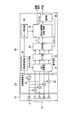
- FIG. 1 is a system diagram showing the configuration of a conventional radar apparatus
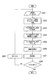
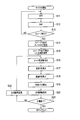
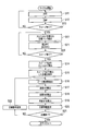
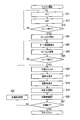
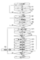
- FIG. 2 is a flowchart showing the operation of the radar apparatus.
- the radar apparatus includes an antenna 10, a transceiver 20 and a signal processor 30.
- the signal swept by the transmitter 21 inside the transceiver 20 is transmitted from the antenna transmission element 11.
- the signals received by the plurality of antenna receiving elements 12 are frequency-converted by the plurality of mixers 22 and sent to the signal processor 30.
- the beat frequency signal from the transmitter / receiver 20 is converted into a digital signal by the AD converter 31, and sent to the up sequence down sequence extraction unit 37 as an element signal (step S201).
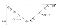
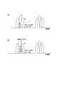
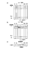
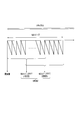
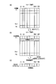
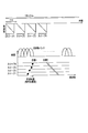
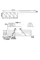
- FIGS. 3 and 4 show transmission / reception up-chirp and down-chirp sweep signals.
- the up-sequence down-sequence extraction unit 37 separates the up-chirp signal and the down-chirp signal from the element signal (digital signal) transmitted from the AD converter 31 and sends it to the FFT unit 33 (step S202).
- the FFT unit 33 performs fast Fourier transform on the up-chirp signal and the down-chirp signal sent from the up-sequence down-sequence extraction unit 37 to convert them into a signal on the frequency axis, and DBF (Digital Beam Forming) Send to part 34.
- DBF Digital Beam Forming
- the DBF unit 34 forms a ⁇ beam (up sequence and down sequence) and a ⁇ beam using the frequency-axis signal sent from the FFT unit 33 (step S203).
- the ⁇ beam formed by the DBF unit 34 is sent to the pairing unit 38, and the ⁇ beam is sent to the angle measuring unit 36.
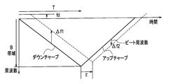
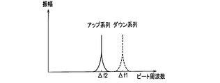
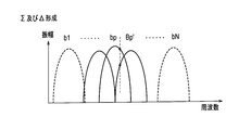
- the pairing unit 38 extracts a frequency having an extreme amplitude as shown in FIG. 5 based on the result of FFT of the up-sequence and down-sequence signals of the ⁇ beam (step S204). This relational expression is shown in the following expression.
- ⁇ f1 Observation frequency of down-chirp signal ⁇ f2; Observation frequency of up-chirp signal fd; Doppler frequency fr;
- B Frequency band R; Target distance T; Sweep time c; Light speed V; Target speed ⁇ ; Wavelength
- step S205 Up-sequence / down-sequence pairing is performed. That is, since the peak frequencies of the down chirp sequence and the up chirp sequence are different, processing for associating the frequency pair is performed.
- step S206 the target distance and speed are calculated (step S206), and the angle is calculated (step S207).
- step S208 it is checked whether or not the cycle is completed. If it is determined in step S208 that the cycle has not ended, processing for moving to the next cycle is performed (step S209). Thereafter, the process returns to step S201, and the above-described process is repeated. On the other hand, if the cycle ends in step S208, the processing of the radar device ends.
- the target distance R and speed V can be calculated by the above processing.
- the peak frequencies of the down-chirp sequence and the up-chirp sequence are different, it is necessary to correspond the frequency pair. Pairing is relatively easy in the case of a single goal or a minority goal.
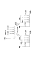
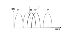
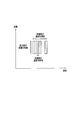
- the target number and the reflection point of the background increase, as shown in FIG. 6, there is a problem that the number of peak values on the frequency axis increases and pairing becomes difficult.
- the conventional radar apparatus has the following problems.
- An object of the present invention is to provide a radar apparatus that can observe a target with high detection performance and high accuracy even when a plurality of targets exist in a wide range from a short distance to a long distance.
- the first invention is a transmitter / receiver for transmitting an FMCW-modulated sweep signal M times, and a fast Fourier transform for M times of the sweep signal received in response to transmission from the transmitter / receiver.
- the beat frequency is calculated by the M sweep phase monopulse, amplitude monopulse or MUSIC.
- the result F (sweep number, target number) is used to perform amplitude integration in the sweep direction for each beat frequency on the beat frequency-sweep axis, and for each frequency bank that exceeds the predetermined threshold, the sweep that exceeds the predetermined threshold Calculate the least square line between the relative distance of the number and the sweep time, and set the target speed by the gradient of the least square line.
- a MRAV processing unit for calculating the distance of the target.
- a transceiver for transmitting an FMCW modulated sweep signal at least twice, an FFT unit for fast Fourier transforming at least two sweep signals received in response to transmission from the transceiver, and an FFT.
- the beat frequency corresponding to each of at least two sweeps by the transmitter / receiver is calculated based on at least two sweep signals obtained by performing Fourier transform in the unit, and the speed is calculated based on the calculated beat frequency difference and time difference.
- an MRAV processing unit that calculates distances and speeds of a plurality of targets by calculating a distance based on the calculated speed and beat frequency.
- a third invention includes a transceiver that transmits an FMCW-modulated sweep signal M times, an FFT unit that fast Fourier transforms M sweep signals received in response to transmission from the transceiver, and an FFT unit.
- the result F (sweep number, target) of the beat frequency calculated by the phase monopulse, amplitude monopulse or MUSIC of the M sweep
- an MRAV processing unit that calculates a distance after calculating the speed based on the smoothed result.
- a fourth invention includes a transceiver that transmits an FMCW-modulated sweep signal M times, an FFT unit that fast Fourier transforms M sweep signals received in response to transmission from the transceiver, and an FFT unit.
- the result F (sweep number, target) of the beat frequency calculated by the phase monopulse, amplitude monopulse or MUSIC of the M sweep MRAV processing unit that calculates the maximum value by Hough transform on the beat frequency-sweep axis using the number)
- the first invention by integrating the amplitude in the sweep direction for each beat frequency on the beat frequency-sweep axis, an integration effect between a plurality of sweeps is obtained to improve the signal detection performance.
- the distance is calculated after calculating the inclination of the straight line extracted by fitting with the least square line and calculating the velocity.
- the second invention it is not necessary to perform pairing in the case of a plurality of targets unlike the conventional radar apparatus, and radar observation with a short cycle time can be realized.
- the third invention since the speed and distance are calculated by smoothing between sweeps, even if there is an error in the relative distance difference, the influence of the error is reduced and the accuracy of speed measurement and distance measurement is improved. be able to.
- the fourth aspect of the invention by performing the Hough transform on the beat frequency-sweep axis, an integration effect between a plurality of sweeps is obtained to improve the signal detection performance. Also, the distance is calculated after calculating the speed by calculating the slope of the straight line extracted by the Hough transform. Thereby, even when there is an error in the relative distance difference, the influence of the error can be reduced and the accuracy of speed measurement and distance measurement can be improved.
- FIG. 1 is a system diagram showing a configuration of a conventional radar apparatus.
- FIG. 2 is a flowchart showing the operation of the conventional radar apparatus.
- FIG. 3 is a diagram showing transmission / reception signals of a conventional radar apparatus.
- FIG. 4 is a diagram showing transmission / reception signals of a conventional radar apparatus.
- FIG. 5 is a diagram for explaining processing of a conventional radar apparatus.
- FIG. 6 is a diagram for explaining the problems of the conventional radar apparatus.
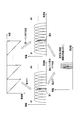
- FIG. 7 is a system diagram showing the configuration of the radar apparatus according to Embodiment 1 of the present invention.
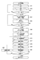
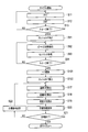
- FIG. 8 is a flowchart showing measurement processing performed by the radar apparatus according to Embodiment 1 of the present invention.
- FIG. 1 is a system diagram showing a configuration of a conventional radar apparatus.
- FIG. 2 is a flowchart showing the operation of the conventional radar apparatus.
- FIG. 3 is a diagram showing transmission / reception signals of a conventional radar apparatus.
- FIG. 4 is a diagram showing
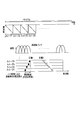
- FIG. 9 is a diagram for explaining a sweep signal performed by the radar apparatus according to Embodiment 1 of the present invention.
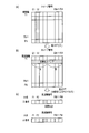
- FIG. 10 is a diagram for explaining how the beat frequency is extracted in the radar apparatus according to Embodiment 1 of the present invention.
- FIG. 11 is a diagram for explaining a processing process in the radar apparatus according to Embodiment 1 of the present invention.
- FIG. 12 is a diagram for explaining another process in the radar apparatus according to Embodiment 1 of the present invention.
- FIG. 13 is a flowchart showing a measurement process performed by the radar apparatus according to Embodiment 2 of the present invention.
- FIG. 14 is a diagram for explaining measurement processing performed by the radar apparatus according to Embodiment 2 of the present invention.
- FIG. 15 is a diagram for explaining the formation of ⁇ and ⁇ in the measurement process performed by the radar apparatus according to Embodiment 2 of the present invention.
- FIG. 16 is a diagram for explaining the calculation of the error voltage in the measurement process performed by the radar apparatus according to Embodiment 2 of the present invention.
- FIG. 17 is a diagram for explaining the calculation of the error voltage in the measurement process performed by the radar apparatus according to Embodiment 3 of the present invention.
- FIG. 18 is a diagram for explaining the calculation of the error voltage in the measurement process performed by the radar apparatus according to Embodiment 3 of the present invention.
- FIG. 19 is a flowchart showing a measurement process performed by the radar apparatus according to Embodiment 4 of the present invention.
- FIG. 20 is a mail diagram for explaining the measurement processing performed by the radar apparatus according to Embodiment 4 of the present invention.
- FIG. 21 is a system diagram showing a configuration of a radar apparatus according to Embodiment 5 of the present invention.
- FIG. 22 is a flowchart showing a measurement process performed by the radar apparatus according to Embodiment 5 of the present invention.
- FIG. 23 is a diagram for explaining measurement processing performed by the radar apparatus according to Embodiment 5 of the present invention.
- FIG. 24 is a diagram for explaining measurement processing performed by the radar apparatus according to Embodiment 5 of the present invention.
- FIG. 25 is a diagram for explaining measurement processing performed by the radar apparatus according to Embodiment 5 of the present invention.
- FIG. 21 is a system diagram showing a configuration of a radar apparatus according to Embodiment 5 of the present invention.
- FIG. 22 is a flowchart showing a measurement process performed by the radar apparatus according to Embodiment 5 of the present invention.
- FIG. 23 is
- FIG. 26 is a diagram for explaining measurement processing performed by the radar apparatus according to Embodiment 5 of the present invention.
- FIG. 27 is a diagram for explaining measurement processing performed by the radar apparatus according to Embodiment 5 of the present invention.
- FIG. 28 is a diagram for explaining measurement processing performed by the radar apparatus according to Embodiments 6 and 7 of the present invention.
- FIG. 29 is a flowchart showing a measurement process performed by a radar apparatus according to Embodiments 6 and 7 of the present invention.
- FIG. 30 is a diagram for explaining a measurement process performed by the radar apparatus according to Example 8 of the present invention.
- FIG. 31 is a flowchart showing a measurement process performed by the radar apparatus according to Embodiment 8 of the present invention.
- FIG. 32 is a flowchart showing a measurement process performed by the radar apparatus according to Embodiment 9 of the present invention.
- FIG. 33 is a diagram for explaining measurement processing performed by the radar apparatus according to Embodiment 9 of the present invention.
- FIG. 34 is a system diagram showing a configuration of a radar apparatus according to Embodiment 10 of the present invention.
- FIG. 35 is a diagram for explaining a sweep signal used in the radar apparatus according to Embodiment 10 of the present invention.
- FIG. 36 is a diagram for explaining a sweep signal used in the radar apparatus according to Embodiment 10 of the present invention.
- FIG. 37 is a system diagram showing a configuration of a radar apparatus according to Embodiment 11 of the present invention.
- FIG. 38 is a diagram for explaining a sweep signal used in the radar apparatus according to Embodiment 11 of the present invention.
- FIG. 39 is a flowchart showing processing performed by the radar apparatus according to Embodiment 11 of the present invention.
- FIG. 40 is a flowchart showing processing performed in the radar apparatus according to Embodiment 12 of the present invention.
- FIG. 41 is a diagram for explaining processing performed by the radar apparatus according to Embodiment 12 of the present invention.
- FIG. 42 is a diagram for explaining processing performed by the radar apparatus according to Embodiment 13 of the present invention.
- FIG. 43 is a flowchart showing processing performed by the radar apparatus according to Embodiment 13 of the present invention.
- FIG. 44 is a diagram for explaining processing performed in the radar apparatus according to Embodiment 14 of the present invention.
- FIG. 45 is a flowchart showing processing performed in the radar apparatus according to Embodiment 14 of the present invention.
- FIG. 46 is a diagram for explaining the Hough transform performed in the radar apparatus according to Embodiment 14 of the present invention.
- FIG. 47 is a diagram for explaining the Hough transform performed by the radar apparatus according to Embodiment 14 of the present invention.
- FIG. 48 is a diagram for explaining the Hough transform performed by the radar apparatus according to Embodiment 14 of the present invention.
- FIG. 49 is a diagram for explaining the Hough transform performed in the radar apparatus according to Embodiment 14 of the present invention.
- FIG. 50 is a diagram for explaining processing performed by the radar apparatus according to Embodiment 15 of the present invention.
- FIG. 51 is a flowchart showing processing performed in the radar apparatus according to Embodiment 15 of the present invention.
- the radar apparatus according to the present invention employs a simple system in which pairing is performed only between the same frequency bank or adjacent banks using a continuous FMCW signal that is easy to mount.
- the radar apparatus employs an MRAV (Measurement Range After Measurement Velocity) method of calculating a distance after calculating a velocity based on a beat frequency.
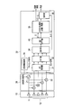
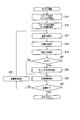
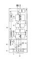
- FIG. 7 is a system diagram showing the configuration of the radar apparatus according to Embodiment 1 of the present invention.
- This radar apparatus includes an antenna 10, a transceiver 20, and a signal processor 30a.
- the antenna 10 includes an antenna transmitting element 11 and a plurality of antenna receiving elements 12.
- the antenna transmission element 11 converts a transmission signal sent as an electrical signal from the transceiver 20 into a radio wave and sends it out.
- the plurality of antenna receiving elements 12 receive external radio waves, convert them into electrical signals, and send them to the transceiver 20 as received signals.
- the transceiver 20 includes a transmitter 21 and a plurality of mixers 22, and the plurality of mixers 22 are provided corresponding to the plurality of antenna receiving elements 12, respectively.
- the transmitter 21 generates a transmission signal in accordance with the transmission control signal sent from the signal processor 30 and sends it to the antenna transmission element 11 and the plurality of mixers 22.
- the plurality of mixers 22 frequency-convert the received signals received from the plurality of antenna receiving elements 12 in accordance with the signals from the transmitter 21 and send the signals to the signal processor 30.
- the signal processor 30a includes an AD converter 31, an FFT unit 32, a DBF unit 34, an MRAV processing unit 35a, an angle measuring unit 36, and a transmission / reception control unit 39.
- the AD converter 31 converts the analog signal sent from the transmitter / receiver 20 into a digital signal according to the timing signal sent from the transmission / reception control unit 39, and sends it to the FFT unit 32 as an element signal.
- the FFT unit 32 converts the element signal sent from the AD converter 31 into a signal on the frequency axis by fast Fourier transform, and sends it to the DBF unit 34.
- the DBF unit 34 uses the signals on the frequency axis sent from the FFT unit 33 to form a ⁇ beam and a ⁇ beam.
- the ⁇ beam formed by the DBF unit 34 is sent to the MRAV processing unit 35a, and the ⁇ beam is sent to the angle measuring unit 36.
- the MRAV processing unit 35a performs ranging and speed measurement based on the ⁇ beam from the DBF unit 34.
- the distance and speed obtained by the distance measurement and speed measurement in the MRAV processing unit 35a are output to the outside.
- the angle measuring unit 36 performs angle measurement based on the ⁇ beam sent from the DBF unit 34.
- the angle obtained by the angle measurement by the angle measuring unit 36 is output to the outside.
- the transmission / reception control unit 39 generates a transmission control signal for starting transmission and sends the transmission control signal to the transmitter 21 of the transmitter / receiver 20, and generates a timing signal that defines the timing for capturing the signal from the transmitter / receiver 20 to perform AD conversion. Send to vessel 31.
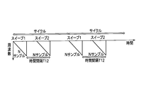
- a sweep 1 that is a frequency-changed sweep signal, that is, an FM-modulated sweep signal, is transmitted from the antenna transmission element 11 and transmitted as shown in FIG.
- the received signal is received by the antenna receiving element 12.
- the received signal is frequency-converted by the transmitter / receiver 20 and sent to the AD converter 31 of the signal processor 30a.
- the AD converter 31 converts the analog signal sent from the transceiver 20 into a digital signal.
- signals of N samples corresponding to each of the time axes T1 to TN are obtained for the elements having the element numbers E1 to EM of the antenna receiving element 12.
- the signal obtained by the AD converter 31 is sent to the FFT unit 32 as an element signal.
- step S11 fast Fourier transform
- the FFT unit 32 performs a fast Fourier transform on the element signal sent from the AD converter 31.
- a signal is obtained.
- the beat frequency signal obtained by the FFT unit 32 is sent to the DBF unit 34.
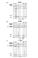
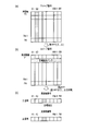
- step S12 DBF processing is performed (step S12). That is, the DBF unit 34 forms a ⁇ beam and a ⁇ beam in the angle direction using the signal on the frequency axis sent from the FFT unit 33. Thereby, as shown in FIG.11 (c), the beam which has a peak in a specific beam number (for example, B2) is formed.
- the ⁇ beam formed by the DBF unit 34 is sent to the MRAV processing unit 35, and the ⁇ beam is sent to the angle measuring unit 36.
- step S13 it is determined whether or not the sweep is finished (step S13). That is, it is checked whether or not the processing for both sweep 1 and sweep 2 has been completed. If the sweep has not ended in step S13, the process returns to step S11, and the above-described process is repeated for sweep 2 that is the next FM-modulated sweep signal.
- step S14 threshold detection of sweep 1 and sweep 2 is performed (step S14). That is, the DBF unit 34 detects the threshold level of the ⁇ beam obtained by the sweep 1 and the sweep 2.
- step S15 the target detected in step S14 is stored (step S15). That is, the DBF unit 34 detects and stores the target from the threshold level detected in step S14.
- the beat frequency is extracted (step S16). That is, as shown in FIG. 10, the MRAV processing unit 35a extracts the beat frequency fp having a peak signal and the bank signal based on the FFT and DBF results of the sweep 1 and the sweep 2.
- an angle ⁇ is calculated (step S19). That is, the angle measuring unit 36 performs angle measurement based on the ⁇ beam sent from the DBF unit 34 and outputs the angle obtained by this angle measurement to the outside.
- step S20 the target information is stored (step S20). That is, the target speed V, distance R, and angle ⁇ calculated in step S17 are stored.
- step S21 it is checked whether or not the goal is finished (step S21). That is, it is checked whether or not the processing for all the targets has been completed.
- step S21 when the target has not ended, the target number is changed to the next number, and the process returns to step S16 and the above-described processing is repeatedly executed. On the other hand, if the target is finished in step S21, the measurement process is finished.
- the radar apparatus in order to transmit / receive an up-chirp or down-chirp sequence signal, pairing in the case of multiple beat targets having the same beat frequency is performed. There is no need to do. Also, radar observation with a short cycle time can be realized.
- the radar apparatus performs digital beam forming (DBF) after performing fast Fourier transform (FFT) to obtain the beat frequency.
- DBF digital beam forming
- FFT fast Fourier transform
- the radar apparatus according to the second embodiment of the present invention employs a method in which a phase monopulse is combined with the MRAV method according to the first embodiment described above.
- the configuration of the radar apparatus according to the second embodiment is the same as the configuration of the radar apparatus according to the first embodiment illustrated in FIG.
- FIG. 13 is a flowchart showing the operation of the radar apparatus according to the second embodiment of the present invention, centering on measurement processing for performing distance measurement / speed measurement and angle measurement.
- symbol used in FIG. 8 is attached
- portions different from the first embodiment will be mainly described.
- the radar apparatus observes the frequency in the bank with high accuracy using the phase monopulse used on the angle axis as the frequency axis as shown in FIGS.
- the phase monopulse (sometimes referred to as phase comparison monopulse) is described in “Supervised by Takashi Yoshida,“ Revised Radar Technology ”, IEICE, pp.274-275 (1996)”.
- an error voltage ⁇ p of the following equation is calculated using ⁇ (f) and ⁇ (f) of the extracted target frequency.
- the phase monopulse processing is performed by the FFT unit 32.
- ⁇ Addition (Received data 1 to N multiplied by weighting 1 and then FFT)
- ⁇ Subtraction (1 to N / 2 of received data is multiplied by -1 and N / 2 + 1 to N is multiplied by weighting 1 and then FFT) *; Complex conjugate Re; Real part
- the reference value ⁇ 0 of the error voltage ⁇ p calculated using the frequency characteristics of ⁇ and ⁇ stored in advance is tabulated (corresponding to ⁇ 0 and frequency f).
- the beat frequency fp is extracted from the observed value ⁇ (step S16). Then, the speed and distance are calculated using the extracted beat frequency fp (steps S17 and S18).
- weights such as tailor weights based on tailor distribution may be multiplied in order to reduce side lobes.
- the Taylor distribution is described in, for example, “Supervised by Takashi Yoshida,“ Revised Radar Technology ”, IEICE, pp.274-275 (1996)”.
- the beat frequency of each sweep signal is calculated with high accuracy based on the phase monopulse error voltage. It can be calculated with high accuracy.
- the radar apparatus according to the third embodiment of the present invention uses an amplitude comparison monopulse instead of the phase monopulse of the radar apparatus according to the second embodiment.
- the configuration of the radar apparatus according to the third embodiment is the same as the configuration of the radar apparatus according to the first embodiment illustrated in FIG. Hereinafter, portions different from the first embodiment will be mainly described.
- the amplitude comparison monopulse (also called amplitude monopulse) is described in “Supervised by Takashi Yoshida,“ Revised Radar Technology ”, IEICE, pp.274-275 (1996)”.
- ⁇ Addition (FFT after multiplying received data 1 to N by weighting 1) ⁇ u; the larger absolute value of (f ⁇ 1) and ⁇ (f + 1), and the error voltage ⁇ p calculated using the frequency characteristics of the absolute values abs ( ⁇ ) and absolute values abs ( ⁇ u) stored in advance
- the reference value ⁇ 0 is tabulated (correspondence between ⁇ 0 and frequency f).
- the beat frequency value fp is extracted based on the observed value ⁇ using the reference table. The speed and distance are calculated using the extracted beat frequency fp.
- the beat frequency of each sweep signal is calculated with high accuracy based on the amplitude monopulse error voltage. Can be calculated with high accuracy.
- a weight such as a tailor weight may be multiplied to reduce the side lobes in addition to ⁇ 1 or 1 as in the radar apparatus according to the second embodiment described above.
- the radar apparatus employs the MUSIC method.
- the MUSIC method is described in “HARRY B.LEE,“ Resolution ”Threshold of Beams“ pace ”MUSIC“ For ”Two“ Closely ”Spaced“ Emitters ”,“ IEEE ”Trans.“ ASSP, ”Vol. 38,“ No. 9, “Sept.” (1990) .
- FIG. 19 is a flowchart illustrating the operation of the radar apparatus according to the fourth embodiment of the present invention, centering on measurement processing for performing distance measurement / speed measurement and angle measurement.
- the same reference numerals as those used in FIG. 7 are given to steps for performing the same or corresponding processing as the measurement processing according to the first embodiment shown in the flowchart of FIG. 8. .
- portions different from the first embodiment will be mainly described.
- the FFT unit 32 performs a fast Fourier transform on the sweep signal
- a bank signal of ⁇ M is extracted around the maximum value bank of the ⁇ signal
- the beat frequency is calculated with high accuracy by applying the beam space type MUSIC.
- This radar apparatus calculates the speed based on the beat frequency difference (distance difference) twice and the time difference, and further calculates the absolute distance based on the beat frequency and the speed, thereby calculating the distance and speed of Nt targets. calculate.
- the beam can be expanded on the frequency axis such as fast Fourier transform (FFT).
- FFT fast Fourier transform
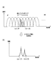
- the procedure is as follows. That is, as shown in FIG. 20A, a target bank whose amplitude exceeds a predetermined threshold is extracted based on the result of the fast Fourier transform (FFT). Then, a correlation matrix Rbb is calculated from ⁇ M banks (2M + 1) of complex signals Xm around the extracted target bank.
- FFT fast Fourier transform
- Rbb Correlation matrix
- X Column vector having elements XM to X0 to XM (2M + 1)
- H Complex conjugate transposition
- the eigenvector Eb of Rbb of the correlation matrix is calculated.
- an eigenvector EN for noise is extracted from the eigenvector Eb.
- the MUSIC spectrum is calculated by the following equation. As shown in FIG. 20 (b), the beat frequency fp having an extreme value in the spectrum is read.
- ws steering column vector having element ws (n) on the time axis
- fs search frequency PRF: repetition frequency n: 1 to N (N is the number of samples)
- EN Eigenvector of correlation matrix
- Rbb H Conjugate transposition
- the beat frequency of each sweep signal is calculated with high accuracy based on the FFT and MUSIC processing. Can be calculated with high accuracy.
- FIG. 21 is a block diagram showing a configuration of a radar apparatus according to Embodiment 5 of the present invention.
- This radar apparatus is configured by adding a second FFT section 40 between the DBF section 34 and the MRAV processing section 35 in the signal processor 30a of the radar apparatus shown in FIG.
- the second FFT unit 40 performs a fast Fourier transform on the signal output from the DBF unit 34.
- a method of integrating between a plurality of sweeps is adopted in order to further improve the SN ratio and improve the frequency resolution within the restriction of the frequency band. Has been.
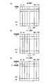
- This radar device transmits an FMCW-modulated sweep signal N times (# 1 to #N), and extracts the local maximum value of the Nt point from the result of the fast Fourier transform of each sweep.
- the radar apparatus performs two M sweeps by extracting a bank of local maximum values from FFT signals of # 1 to # N1 (M sweep) and # N2 to #N (M sweep) sweeps.
- the beat frequency of the bank signal having the maximum value among the results of each fast Fourier transform is calculated.
- the radar apparatus calculates the speed based on the two beat frequency differences (distance difference) and the time difference, and calculates the absolute distance based on the beat frequency and the speed, thereby calculating the distance and speed of the Nt targets. To do.
- FIG. 27 shows the state of each FFT in the two M sweeps.
- a second M-sample FFT is performed.
- the first FFT unit 32 calculates ⁇ (difference between 1 to N / 2 and N / 2 + 1 to N) in addition to the sum ⁇ of N samples.
- a ⁇ and ⁇ signal by two-stage FFT is obtained by calculating the sum of ⁇ and ⁇ of M samples as a result of the first FFT. Thereafter, a phase monopulse calculation may be performed to calculate a highly accurate frequency fp.
- FIG. 22 is a flowchart showing the operation of the radar apparatus according to the fifth embodiment of the present invention, centering on measurement processing for performing distance measurement / speed measurement and angle measurement.
- the same reference numerals as those used in FIG. 8 are given to steps for performing the same or corresponding processes as the measurement process according to the first embodiment shown in the flowchart of FIG. 8. In the following, a description will be given centering on differences from the first embodiment.
- N sweeps are transmitted and received, and the first FFT is executed by the FFT unit 32 for each sweep (steps S11 to S13).
- a target bank exceeding a predetermined threshold is extracted (step S51).
- the target bank of each sweep is subjected to a second FFT by the second FFT unit 39 (step S52).
- the peak beat frequency fp is read.
- speed calculation (step S17) and distance calculation (step S18) are performed using the calculated beat frequency fp.
- N sweeps are transmitted and received, and the first FFT is executed by the FFT unit 32 for each sweep (steps S11 to S13).
- the ⁇ signal and the ⁇ signal are calculated, and a target bank in which the absolute value of the ⁇ signal exceeds a predetermined threshold is extracted (step S51).
- the ⁇ signal and ⁇ signal of the target bank of each sweep are subjected to a second FFT by the second FFT unit 40 (step S52).
- the frequency fp is calculated using the ⁇ signal and the ⁇ signal, and the distance and the speed are calculated using the calculated frequency fp.
- the extracted bank signal of each sweep signal is further subjected to the second FFT between sweeps, so that the resolution is higher than that of the bank using only the first FFT.
- the target position and speed can be extracted.
- FIG. 29 is a flowchart showing the operation of the radar apparatus according to Embodiment 6 of the present invention, centering on measurement processing for measuring distance / speed measurement and angle measurement.
- the same reference numerals as those used in FIG. 22 are assigned to steps that perform the same or corresponding processes as the measurement process according to the fifth embodiment shown in the flowchart of FIG. In the following, a description will be given centering on differences from the fifth embodiment.
- N sweeps are transmitted and received, and FFT is executed for each sweep (steps S11 to S13).
- a target bank whose amplitude exceeds a predetermined threshold is extracted (step S51).
- ⁇ and ⁇ are calculated by the second FFT unit 40 using the target banks E1 to EM extracted in step S51.
- an error voltage ⁇ p of the following equation is calculated using ⁇ (f) and ⁇ (f) of the extracted target frequency.
- ⁇ Addition (FFT after multiplying E1 to EM by weight 1)
- ⁇ Subtraction (E1 to EM / 2 multiplied by ⁇ 1, EM / 2 + 1 to EM weighted by 1 and then FFT) *; Complex conjugate Re; Real part
- the reference value ⁇ 0 of the error voltage ⁇ p calculated using the frequency characteristics of ⁇ and ⁇ stored in advance is tabulated (corresponding to ⁇ 0 and the frequency f).
- the frequency value fp is extracted based on the observed value ⁇ (step S16).
- speed calculation step S17
- distance calculation step S18
- the beat frequency is calculated with high accuracy by calculating the frequency using the phase monopulse.
- the target position and speed can be extracted with high accuracy.
- a weight such as a tailor weight may be multiplied to reduce the side lobes in addition to ⁇ 1 or 1 as in the radar apparatus according to the second embodiment described above.
- N sweeps are transmitted and received, and the first FFT is executed for each sweep (steps S11 to S13).
- a target bank whose amplitude exceeds a predetermined threshold is extracted (step S51).
- the absolute value abs ( ⁇ (f ⁇ 1)) and the absolute value abs ( ⁇ (F + 1)) are compared, and the larger one is set as the absolute value abs ( ⁇ u).
- ⁇ Addition (FFT after multiplying received data 1 to N by weighting 1) ⁇ u; the larger absolute value of ⁇ (f ⁇ 1) and ⁇ (f + 1), and the reference value of the error voltage ⁇ p calculated using the frequency characteristics of abs ( ⁇ ) and abs ( ⁇ u) stored in advance ⁇ 0 is tabulated (corresponding to ⁇ 0 and frequency f).
- the beat frequency value fp is extracted based on the observed value ⁇ using the reference table. The distance and speed are calculated using the calculated beat frequency fp.
- the beat frequency is calculated with high accuracy by calculating the frequency using the amplitude monopulse.
- the target position and speed can be extracted with high accuracy.
- a weight such as a tailor weight may be multiplied by a weight other than ⁇ 1 or 1 in order to reduce the side lobe, similarly to the radar apparatus according to the second embodiment described above.
- the radar apparatus according to Example 8 of the present invention calculates the beat frequency by FFT and MUSIC processing of M sweep when calculating each local maximum value from two M sweep signals. .
- FIG. 31 is a flowchart showing the operation of the radar apparatus according to the eighth embodiment of the present invention, centering on measurement processing for measuring distance / speed measurement and angle measurement.
- the same reference numerals as those used in FIG. 22 are given to steps for performing the same or corresponding processes as the measurement process according to the fifth embodiment shown in the flowchart of FIG. 22. In the following, a description will be given centering on differences from the fifth embodiment.
- a target bank whose amplitude exceeds a predetermined threshold is extracted based on the result of FFT in steps S11 to S13 (step S51).
- a correlation matrix Rbb is calculated based on the complex signal Xm for M sweeps of the target bank.
- Rbb Correlation matrix
- X Column vector having elements X1 to XM (M) H: Complex conjugate transposition
- an eigenvector Eb of the correlation matrix Rbb is calculated.
- an eigenvector EN for noise in the eigenvector Eb is extracted, a MUSIC spectrum is calculated by the following equation using the eigenvector EN and a steering vector w for searching for a frequency, and the beat frequency at which the spectrum has an extreme value is calculated.
- fp is read. This MUSIC process is performed by the second FFT unit 39 (step S71).
- Rbb H Conjugate transposition
- the frequency is calculated by the FFT and MUSIC processing, so that the beat can be accurately performed.
- the frequency can be extracted, and the target position and speed can be extracted with high accuracy.
- the radar apparatus When the sweep signal is a real signal (not a complex signal), the radar apparatus according to Embodiment 9 of the present invention extracts a positive (or negative) signal from the beat frequency by performing a complex Fourier transform on the sampled signal. Thus, a complex signal is obtained. In this case, depending on the distance and speed, the target is actually observed as positive (or negative) even if the beat frequency is negative (or positive), and therefore the distance and speed may be wrong. In this case, it can be determined that the beat frequency is negative (positive) based on the following principle.
- FIG. 32 is a flowchart showing the operation of the radar apparatus according to Embodiment 9 of the present invention, centering on measurement processing for measuring distance / speed measurement and angle measurement.
- the same reference numerals as those used in FIG. 8 are assigned to steps that perform the same or corresponding processes as the measurement process according to the first embodiment shown in the flowchart of FIG. In the following, a description will be given centering on differences from the fifth embodiment.
- the negative velocity observation method by the MRAV method is performed by the following procedure. After the distance difference between the two sweeps is observed, the target velocity V is calculated based on the position change and time (step S17). Next, the distance R is calculated from the beat frequency using the target speed V calculated in step S17 (step S18). Next, the angle ⁇ is calculated (step S19). Next, it is checked whether or not the distance R is negative (step S61). If the distance R is negative in step S61, the sign inversion unit (not shown) inverts the signs of the distance R, the speed V, and the angle ⁇ (step S62). On the other hand, if the distance R is not negative in step S61, the process of step S62 is skipped.
- the radar apparatus when a real sampling frequency is subjected to complex Fourier transform and only a positive (or negative) beat frequency is observed, a true target signal is obtained. Even when the beat frequency has a negative (or positive) beat frequency, the correct sign can be determined based on the calculated sign of the distance and converted to the correct sign of the distance, speed, and angle.
- the radar apparatus according to Example 10 of the present invention employs the method adopted in Example 1 or Example 2 when the observation target exists in a wide range from a short distance to a long distance and the speed range is wide.
- FIG. 34 is a system diagram showing a configuration of a radar apparatus according to Embodiment 10 of the present invention.
- This radar apparatus is configured by adding a sweep control unit 41 to the radar apparatus according to the first embodiment.
- the sweep control unit 41 sends to the transmission / reception control unit 39 and the MRAV processing unit 35a a control signal for transmitting a signal in which the gradient of the sweep signal is increased at a short distance and the gradient of the sweep signal is decreased at a long distance. Control these.
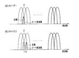
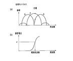
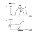
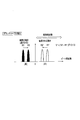
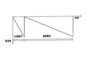
- the transmission signal In the case of a short-distance target, the transmission signal is in the vicinity of DC on the beat frequency axis after the FFT, and is susceptible to noise due to the wraparound of the transmission signal to the reception side.
- the separation frequency increases from the DC component and is not easily affected by noise. For this reason, as shown in FIGS. 35 and 36, the transmission / reception signals are divided into short distance and long distance, and the frequency gradient is increased at the short distance and the frequency gradient is decreased at the long distance.
- the band B and the PRF are the same, the number of points decreases at a short distance.
- the effect of reducing noise is greater than the signal integration effect, and the required S / N ratio can be ensured. Since the number of points is large at a long distance, the signal integration effect is high and the required S / N ratio can be ensured.
- Signal can be transmitted and received, and radar observation at a high S / N ratio can be realized.
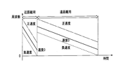
- FIG. 38 shows an example of a plurality of transmission / reception sweep signals for short distance and long distance.
- FIG. 37 is a system diagram showing a configuration of a radar apparatus according to Embodiment 11 of the present invention.
- This radar apparatus is configured such that an angle signal is sent from the angle measuring section 36 of the radar apparatus according to the tenth embodiment to the sweep control section 38.
- a high weight may be given to a target having a large relative speed that is approaching at a close distance, and can be expressed by the following equation.
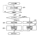
- FIG. 39 is a flowchart showing a procedure for selecting the optimum sweep interval (sweep number) using this risk level.
- Cr k (constant) ⁇ V / R is calculated for each target (steps S71 and S72).
- the maximum value is extracted if it is positive, and the minimum value is extracted if it is negative (steps S74 and S76).
- a sweep is selected so as to maximize the target observation accuracy corresponding to the extracted Cr (steps S75 and S76).
- the sweep Ts (or the sweep number close to Ts) may be selected by the following equation.
- the time between sweeps is shorter when the target speed is fast, and longer when the target speed is slow. Therefore, when the target speed is unknown, it is possible to select an optimum sweep corresponding to the target by determining the target whose speed accuracy is to be increased using the degree of risk.
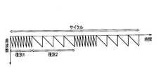
- the radar apparatus according to Embodiment 12 of the present invention is such that different sweeps are periodically changed for each cycle.
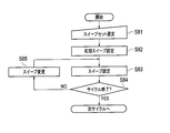
- FIG. 40 is a flowchart illustrating processing of the radar apparatus according to the twelfth embodiment. This process is performed by the sweep control unit 38.
- step S81 a sweep set is selected (step S81).
- step S82 an initial sweep is set (step S82).
- step S83 a sweep is set (step S83).
- step S84 it is checked whether or not the cycle is completed (step S84).
- step S84 if the cycle has not ended, the sweep is changed (step S85). Then, it returns to step S83 and the process mentioned above is repeated. On the other hand, if the cycle ends in step S84, the process ends, and the process proceeds to the next cycle.
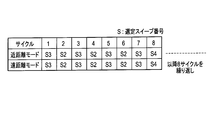
- FIG. 41 is a diagram showing an example of a cycle.
- the sweep number is selected by repeating eight cycles of S3-S2-S3-S2-S3-S2-S3-S4.
- the speed and distance accuracy can be improved for any target by periodically changing different sweeps for each cycle.
- the radar apparatus according to Embodiment 13 of the present invention obtains a smoothing effect by using M multiple sweep signals.
- the configuration of the radar apparatus according to Embodiment 13 is the same as that of the radar apparatus according to Embodiment 10 shown in FIG.
- FIG. 43 is a flowchart illustrating processing of the radar apparatus according to the thirteenth embodiment.
- the beat frequency fp is calculated by the M sweep phase monopulse (amplitude monopulse, MUSIC) (steps S91 to S94), and the equation (5) is used.
- the result converted into the relative distance is R (m, n) (sweep number m, target number n).
- step S95 Smoothing is performed by a smoothing filter between S (m, n) sweeps (step S95), and the speed is calculated based on the result, and then the relative distance is calculated (steps S17 to S18).
- the processing of steps S91 to S94, step S95, and steps S17 to S18 is performed by the MRAV processing unit 35.
- v speed T1M: time interval of sweep 1
- M fp beat frequency
- ⁇ wavelength
- B band T: sweep time
- the smoothing filter only needs to obtain a smoothing effect, such as a least square filter, Other filters can also be used.
- the first and M-th sweeps are used, but other sweep intervals may be used as long as a smoothing effect can be obtained.
- the relative distance difference for calculating the speed is observed by a plurality of sweeps (a plurality of times) and smoothed. Therefore, even if there is an error in the relative distance difference, the influence of the error can be reduced, and the accuracy of speed measurement and distance measurement can be improved.
- the MRAV method described above depends on the accuracy of the relative distance difference (beat frequency) between two sweeps. For this reason, when the SN ratio is small, the speed and distance may be deteriorated.
- the radar apparatus according to Embodiment 14 of the present invention obtains an integration effect using Hough transform using M multiple sweep signals, and performs smoothing. It is an effect.
- the configuration of the radar apparatus according to Embodiment 14 is the same as that of the radar apparatus according to Embodiment 10 shown in FIG.
- FIG. 45 is a flowchart illustrating processing of the radar apparatus according to the fourteenth embodiment.
- the beat frequency fp is calculated by the M sweep phase monopulse (amplitude monopulse, MUSIC), and F (sweep number m, target number n) and (Steps S92 to S94).
- Vp (RM-R1) / (TM-T1) here, R1, RM: Relative distance corresponding to sweep 1 and sweep M on the straight X axis (beat frequency axis) T1, TM: Time of the start point of sweep 1 and sweep M Next, using beat frequency fp and velocity Vp, The distance is calculated by the following equation (step S18).
- the processes of steps S92 to S94, steps S101 to S102, and steps S17 to S18 are performed by the MRAV processing unit 35.
- Vp Velocity fp: Beat frequency ⁇ : Wavelength B: Band T: Sweep time Note that the beat frequency axis-sweep axis was used when performing the Hough transform, but the beat frequency is relative using equation (5). After conversion to distance, Hough transform may be used on the relative distance-sweep axis.
- the Hough transform is a technique for extracting a straight line from an image.
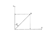
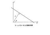
- a straight line on the XY plane is expressed in polar coordinates, as shown in FIGS. 46 and 47, the following equation is obtained.
- the straight line and ⁇ , ⁇ correspond uniquely.
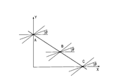
- three points A, B, and C on the straight line are considered.
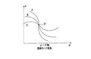
- a curve when the angle ⁇ is changed in order through each point is represented by the ⁇ - ⁇ axis as shown in FIG.
- the three curves intersect at a certain point, and this point ( ⁇ 0, ⁇ 0) represents a common straight line on the XY axis.
- the relative distance difference for calculating the speed is observed in a plurality of sweeps (a plurality of times), and the relative distance difference-the sweep time is on the axis.
- the Hough transform By performing the Hough transform, the integration effect between a plurality of sweeps is obtained and the signal detection performance is improved.
- the speed is calculated, and then the distance is calculated to reduce the influence of the error even if there is an error in the relative distance difference. The accuracy of distance measurement can be improved.
- the radar apparatus according to Embodiment 15 of the present invention obtains an integration effect by performing amplitude integration using M multiple sweep signals, and also provides a smoothing effect. Is obtained.
- the configuration of the radar apparatus according to Embodiment 15 is the same as that of the radar apparatus according to Embodiment 10 shown in FIG.
- FIG. 51 is a flowchart illustrating processing of the radar apparatus according to the fifteenth embodiment.
- the beat frequency fp (corresponding to the relative distance Rp according to the equation (5)) is obtained from the M sweep phase monopulse (amplitude monopulse, MUSIC). Calculated and set to F (sweep number m, target number n) (steps S92 to S94).
- amplitude integration (video integration) is performed for each frequency bank from the beat frequency-sweep axis using F (m, n) (step S111), and a frequency bank fb exceeding a predetermined threshold is extracted (step S111). Step S112).
- the least square line between the sweep time m and the relative distance Rp which can be expressed by the following equation, is calculated for the frequency bank fb by the sweep F (m, n) exceeding the threshold (step S114).
- the speed is calculated from the gradient of the power line (step S17).
- step S18 using the beat frequency fp and the velocity Vp, the distance is calculated by the following equation (step S18).
- steps S92 to S94, steps S111 to 114, and steps S17 to S18 are performed by the MRAV processing unit 35.
- Vp speed fp: beat frequency ⁇ : wavelength B: band T: sweep time
- fp speed fp: beat frequency
- ⁇ wavelength
- fp used in the equation (19) an average value or the like in each sweep may be used.
- the relative distance difference for calculating the speed is observed in a plurality of sweeps (a plurality of times), and the relative distance difference-the sweep time is on the axis.
- the distance is calculated after calculating the speed by calculating the slope of the extracted straight line by fitting with the least square line.
- the present invention can be used in a radar device that measures the distance to a vehicle and the speed of the vehicle.
Landscapes
- Engineering & Computer Science (AREA)
- Radar, Positioning & Navigation (AREA)
- Remote Sensing (AREA)
- Computer Networks & Wireless Communication (AREA)
- Physics & Mathematics (AREA)
- General Physics & Mathematics (AREA)
- Radar Systems Or Details Thereof (AREA)
Abstract
La présente invention concerne un dispositif équipé d'un émetteur-récepteur (20), des signaux de balayage soumis à une modulation FMCW étant émis au moins deux fois, d'une unité FFT (32), au moins deux cycles de signaux de balayage reçus en réponse à l'émission par l'émetteur-récepteur étant soumis à des transformées rapides de Fourier, et d'une unité de traitement MRAV (35a), des fréquences de battement correspondant à chacun des deux cycles de balayage ou plus par l'émetteur-récepteur étant calculées sur la base d'au moins deux cycles de signaux de balayage obtenus par la réalisation de transformées de Fourier dans l'unité FFT, des vitesses étant calculées sur la base de différences de fréquences de battement et de différences de temps qui sont calculées, et des distances étant calculées sur la base de vitesses et de fréquences de battement qui sont calculées, ce qui donne des calculs de distances et de vitesses d'une pluralité de cibles.
Priority Applications (3)
| Application Number | Priority Date | Filing Date | Title |
|---|---|---|---|
| US12/996,058 US20110122013A1 (en) | 2009-05-20 | 2010-03-19 | Radar apparatus |
| EP10777616A EP2434309A1 (fr) | 2009-05-20 | 2010-03-19 | Dispositif radar |
| CN2010800012066A CN101971050A (zh) | 2009-05-20 | 2010-03-19 | 雷达装置 |
Applications Claiming Priority (2)
| Application Number | Priority Date | Filing Date | Title |
|---|---|---|---|
| JP2009121902A JP5468304B2 (ja) | 2009-05-20 | 2009-05-20 | レーダ装置 |
| JP2009-121902 | 2009-05-20 |
Publications (1)
| Publication Number | Publication Date |
|---|---|
| WO2010134381A1 true WO2010134381A1 (fr) | 2010-11-25 |
Family
ID=43126070
Family Applications (1)
| Application Number | Title | Priority Date | Filing Date |
|---|---|---|---|
| PCT/JP2010/054839 WO2010134381A1 (fr) | 2009-05-20 | 2010-03-19 | Dispositif radar |
Country Status (5)
| Country | Link |
|---|---|
| US (1) | US20110122013A1 (fr) |
| EP (1) | EP2434309A1 (fr) |
| JP (1) | JP5468304B2 (fr) |
| CN (1) | CN101971050A (fr) |
| WO (1) | WO2010134381A1 (fr) |
Cited By (1)
| Publication number | Priority date | Publication date | Assignee | Title |
|---|---|---|---|---|
| WO2017208670A1 (fr) * | 2016-05-30 | 2017-12-07 | 日本電気株式会社 | Dispositif de détection d'objet, système radar monté sur véhicule, système radar de surveillance, procédé de détection d'objet et programme |
Families Citing this family (34)
| Publication number | Priority date | Publication date | Assignee | Title |
|---|---|---|---|---|
| JP5656505B2 (ja) * | 2010-08-12 | 2015-01-21 | 三菱電機株式会社 | レーダ装置 |
| JP5660973B2 (ja) * | 2011-05-20 | 2015-01-28 | 三菱電機株式会社 | レーダ装置 |
| JP5871559B2 (ja) * | 2011-10-20 | 2016-03-01 | 三菱電機株式会社 | レーダ装置 |
| WO2013088938A1 (fr) * | 2011-12-12 | 2013-06-20 | 三菱電機株式会社 | Dispositif radar |
| KR101185480B1 (ko) | 2012-03-15 | 2012-10-02 | 국방과학연구소 | 고속 이동체의 탐지/추적을 위한 fmcw 레이다에서 비트주파수의 정확도 향상 기법 |
| JP6275370B2 (ja) * | 2012-04-11 | 2018-02-07 | 三菱電機株式会社 | レーダ装置 |
| ITTO20120417A1 (it) * | 2012-05-09 | 2013-11-10 | St Microelectronics Srl | Procedimento e dispositivi per elaborare segnali radar, ad esempio per sistemi di sicurezza stradale, relativo prodotto informatico |
| JP6092596B2 (ja) * | 2012-11-28 | 2017-03-08 | 富士通テン株式会社 | レーダ装置、および、信号処理方法 |
| US8884814B2 (en) * | 2012-12-06 | 2014-11-11 | Chung Shan Institute Of Science And Technology, Armaments Bureau, M. N.D. | Processing method for FMCW radar signal with dual pulse repetition frequency |
| CN103630888B (zh) * | 2013-02-27 | 2017-03-22 | 中国科学院电子学研究所 | 基于对称三角lfmcw雷达的高精度实时微波测速测距装置 |
| JP2015129695A (ja) * | 2014-01-08 | 2015-07-16 | 株式会社東芝 | パルス圧縮レーダ装置及びそのレーダ信号処理方法 |
| JP6222523B2 (ja) * | 2014-03-11 | 2017-11-01 | 日本電気株式会社 | 移動目標抽出システム、移動目標抽出方法、情報処理装置およびその制御方法と制御プログラム |
| DE102014107343A1 (de) * | 2014-05-26 | 2015-11-26 | Hella Kgaa Hueck & Co. | Verfahren zum Betreiben eines Radarsensors |
| US9841497B2 (en) * | 2014-06-05 | 2017-12-12 | Infineon Technologies Ag | Method, device and system for processing radar signals |
| DE102014212281A1 (de) * | 2014-06-26 | 2015-12-31 | Robert Bosch Gmbh | Radarmessverfahren mit unterschiedlichen Sichtbereichen |
| JP6305259B2 (ja) * | 2014-07-25 | 2018-04-04 | 株式会社東芝 | レーダシステム及びそのレーダ信号処理方法 |
| JP6382635B2 (ja) * | 2014-08-22 | 2018-08-29 | 株式会社東芝 | レーダシステム及びそのレーダ信号処理方法 |
| US9784828B2 (en) * | 2014-08-27 | 2017-10-10 | Texas Insturments Incorporated | FMCW doppler processing algorithm for achieving CW performance |
| JP5925264B2 (ja) * | 2014-09-10 | 2016-05-25 | 三菱電機株式会社 | レーダ装置 |
| KR102303236B1 (ko) * | 2014-11-20 | 2021-09-16 | 현대모비스 주식회사 | Fmcw 레이더 시스템 및 그 동작방법 |
| JP6352837B2 (ja) * | 2015-03-02 | 2018-07-04 | 株式会社東芝 | レーダシステム及びそのレーダ信号処理方法 |
| US10613208B2 (en) * | 2015-05-15 | 2020-04-07 | Texas Instruments Incorporated | Low complexity super-resolution technique for object detection in frequency modulation continuous wave radar |
| US10078131B2 (en) * | 2015-09-15 | 2018-09-18 | Texas Instruments Incorporated | Method and apparatus for FMCW radar processing |
| EP3907529A1 (fr) * | 2016-07-01 | 2021-11-10 | Veoneer Sweden AB | Radar de véhicule pour détection de l'environnement |
| US10641884B2 (en) * | 2017-01-26 | 2020-05-05 | Mitsumi Electric Co., Ltd. | Radar transceiver |
| WO2019008640A1 (fr) * | 2017-07-03 | 2019-01-10 | 三菱電機株式会社 | Dispositif de traitement de signal, procédé de traitement de signal, programme de traitement de signal, et système radar |
| CN107462884A (zh) * | 2017-07-25 | 2017-12-12 | 上海航征测控系统有限公司 | 一种基于调频连续波雷达的运动目标检测方法及系统 |
| DE102017119624A1 (de) * | 2017-08-28 | 2019-04-18 | HELLA GmbH & Co. KGaA | Verfahren zum Betrieb eines Radarsystems eines Fahrzeuges |
| EP3683600B1 (fr) * | 2017-12-27 | 2022-08-24 | Mitsubishi Electric Corporation | Dispositif radar laser |
| JP7056212B2 (ja) * | 2018-02-20 | 2022-04-19 | 株式会社デンソー | 方位推定方法および装置 |
| US10962636B2 (en) * | 2018-08-13 | 2021-03-30 | GM Global Technology Operations LLC | Range and direction of arrival migration with doppler ambiguity estimation |
| CN109557536B (zh) * | 2018-11-30 | 2020-10-27 | 四川九洲防控科技有限责任公司 | 一种测角方法、测角装置及测角系统 |
| CN111521988B (zh) * | 2019-02-01 | 2023-11-14 | 比亚迪股份有限公司 | 基于波束形成的雷达测角方法、装置、雷达和车辆 |
| CN111232778B (zh) * | 2020-03-04 | 2022-06-14 | 日立楼宇技术(广州)有限公司 | 电梯轿厢的人数统计方法及其装置 |
Citations (5)
| Publication number | Priority date | Publication date | Assignee | Title |
|---|---|---|---|---|
| JPH11281729A (ja) * | 1998-03-31 | 1999-10-15 | Toyota Central Res & Dev Lab Inc | ビーム切替型レーダー装置 |
| JP2006242695A (ja) * | 2005-03-02 | 2006-09-14 | Denso Corp | 車載レーダ装置 |
| JP2007286033A (ja) * | 2006-03-23 | 2007-11-01 | Omron Corp | 電波探知装置および方法 |
| JP2009069124A (ja) * | 2007-09-18 | 2009-04-02 | Mitsubishi Electric Corp | レーダ装置 |
| JP2009293968A (ja) * | 2008-06-03 | 2009-12-17 | Fujitsu Ten Ltd | 信号処理装置、及びレーダ装置 |
Family Cites Families (5)
| Publication number | Priority date | Publication date | Assignee | Title |
|---|---|---|---|---|
| CN1023515C (zh) * | 1991-06-28 | 1994-01-12 | 中国人民解放军空军第五研究所 | 自相关异地收发雷达定位法 |
| WO1998002760A1 (fr) * | 1996-06-28 | 1998-01-22 | Milkovich Systems Engineering | Processeur ameliore de detection de transformees de fourier rapides mettant en oeuvre des principes evolues dans le domaine des frequences |
| JP2002257928A (ja) * | 2001-03-06 | 2002-09-11 | Murata Mfg Co Ltd | レーダ |
| WO2006013614A1 (fr) * | 2004-08-02 | 2006-02-09 | Mitsubishi Denki Kabushiki Kaisha | Radar |
| CN101042435B (zh) * | 2006-03-23 | 2011-03-23 | 欧姆龙汽车电子株式会社 | 单脉冲式雷达装置 |
-
2009
- 2009-05-20 JP JP2009121902A patent/JP5468304B2/ja active Active
-
2010
- 2010-03-19 US US12/996,058 patent/US20110122013A1/en not_active Abandoned
- 2010-03-19 CN CN2010800012066A patent/CN101971050A/zh not_active Withdrawn
- 2010-03-19 WO PCT/JP2010/054839 patent/WO2010134381A1/fr active Application Filing
- 2010-03-19 EP EP10777616A patent/EP2434309A1/fr not_active Withdrawn
Patent Citations (5)
| Publication number | Priority date | Publication date | Assignee | Title |
|---|---|---|---|---|
| JPH11281729A (ja) * | 1998-03-31 | 1999-10-15 | Toyota Central Res & Dev Lab Inc | ビーム切替型レーダー装置 |
| JP2006242695A (ja) * | 2005-03-02 | 2006-09-14 | Denso Corp | 車載レーダ装置 |
| JP2007286033A (ja) * | 2006-03-23 | 2007-11-01 | Omron Corp | 電波探知装置および方法 |
| JP2009069124A (ja) * | 2007-09-18 | 2009-04-02 | Mitsubishi Electric Corp | レーダ装置 |
| JP2009293968A (ja) * | 2008-06-03 | 2009-12-17 | Fujitsu Ten Ltd | 信号処理装置、及びレーダ装置 |
Non-Patent Citations (3)
| Title |
|---|
| HARRY B. LEE: "Resolution Threshold of Beamspace MUSIC For Two Closely Spaced Emitters", IEEE TRANS. ASSP, vol. 38, no. 9, September 1990 (1990-09-01) |
| TAKASHI YOSHIDA: "Radar Technology", 1996, INSTITUTE OF ELECTRONICS, INFORMATION AND COMMUNICATION ENGINEERS, article "Radar Technology, revised version", pages: 274,275 |
| TAKASHI YOSHIDA: "Radar Technology, revised version", 1996, INSTITUTE OF ELECTRONICS, INFORMATION AND COMMUNICATION ENGINEERS, pages: 274,275 |
Cited By (3)
| Publication number | Priority date | Publication date | Assignee | Title |
|---|---|---|---|---|
| WO2017208670A1 (fr) * | 2016-05-30 | 2017-12-07 | 日本電気株式会社 | Dispositif de détection d'objet, système radar monté sur véhicule, système radar de surveillance, procédé de détection d'objet et programme |
| JPWO2017208670A1 (ja) * | 2016-05-30 | 2019-03-28 | 日本電気株式会社 | 物体検知装置、車載レーダシステム、監視レーダシステム、物体検知方法及びプログラム |
| US11194033B2 (en) | 2016-05-30 | 2021-12-07 | Nec Corporation | Object sensing device, automotive radar system, surveillance radar system, object sensing method, and program |
Also Published As
| Publication number | Publication date |
|---|---|
| US20110122013A1 (en) | 2011-05-26 |
| JP5468304B2 (ja) | 2014-04-09 |
| CN101971050A (zh) | 2011-02-09 |
| EP2434309A1 (fr) | 2012-03-28 |
| JP2010271115A (ja) | 2010-12-02 |
Similar Documents
| Publication | Publication Date | Title |
|---|---|---|
| JP5468304B2 (ja) | レーダ装置 | |
| JP5407272B2 (ja) | レーダ装置 | |
| JP5247068B2 (ja) | レーダ装置 | |
| US10914818B2 (en) | Angle-resolving FMCW radar sensor | |
| CN104280728B (zh) | 雷达传感器与用于运行雷达传感器的方法 | |
| JP4665962B2 (ja) | 目標物検出装置 | |
| JP5871559B2 (ja) | レーダ装置 | |
| US8947293B2 (en) | Radar apparatus | |
| JP5578866B2 (ja) | レーダ装置 | |
| CN108885254B (zh) | 物体检测装置 | |
| JP6576595B2 (ja) | レーダ装置 | |
| JP3821688B2 (ja) | レーダ装置 | |
| CN105467381A (zh) | 雷达装置 | |
| EP4009074B1 (fr) | Procédé et système mimo radar de multiplexage à division de doppler codés co-prime (cpc) | |
| JP2009025159A (ja) | レーダ装置 | |
| JP5656505B2 (ja) | レーダ装置 | |
| Kim et al. | Extrapolation-RELAX estimator based on spectrum partitioning for DOA estimation of FMCW radar | |
| JP2010175457A (ja) | レーダ装置 | |
| JP5508877B2 (ja) | レーダ装置 | |
| JP7160561B2 (ja) | 方位演算装置及び方位演算方法 | |
| JP2010281605A (ja) | レーダ装置 | |
| JP2014153088A (ja) | レーダ装置および追尾処理装置 | |
| JP5491981B2 (ja) | レーダ装置 | |
| JP6161311B2 (ja) | レーダ装置及び目標検出方法 | |
| WO2022249552A1 (fr) | Dispositif de traitement d'informations et procédé de traitement d'informations |
Legal Events
| Date | Code | Title | Description |
|---|---|---|---|
| WWE | Wipo information: entry into national phase |
Ref document number: 201080001206.6 Country of ref document: CN |
|
| WWE | Wipo information: entry into national phase |
Ref document number: 12996058 Country of ref document: US |
|
| WWE | Wipo information: entry into national phase |
Ref document number: 2010777616 Country of ref document: EP |
|
| 121 | Ep: the epo has been informed by wipo that ep was designated in this application |
Ref document number: 10777616 Country of ref document: EP Kind code of ref document: A1 |
|
| NENP | Non-entry into the national phase |
Ref country code: DE |