WO2010134381A1 - Radar device - Google Patents
Radar device Download PDFInfo
- Publication number
- WO2010134381A1 WO2010134381A1 PCT/JP2010/054839 JP2010054839W WO2010134381A1 WO 2010134381 A1 WO2010134381 A1 WO 2010134381A1 JP 2010054839 W JP2010054839 W JP 2010054839W WO 2010134381 A1 WO2010134381 A1 WO 2010134381A1
- Authority
- WO
- WIPO (PCT)
- Prior art keywords
- sweep
- signal
- calculated
- radar apparatus
- beat frequency
- Prior art date
Links
Images
Classifications
-
- G—PHYSICS
- G01—MEASURING; TESTING
- G01S—RADIO DIRECTION-FINDING; RADIO NAVIGATION; DETERMINING DISTANCE OR VELOCITY BY USE OF RADIO WAVES; LOCATING OR PRESENCE-DETECTING BY USE OF THE REFLECTION OR RERADIATION OF RADIO WAVES; ANALOGOUS ARRANGEMENTS USING OTHER WAVES
- G01S13/00—Systems using the reflection or reradiation of radio waves, e.g. radar systems; Analogous systems using reflection or reradiation of waves whose nature or wavelength is irrelevant or unspecified
- G01S13/02—Systems using reflection of radio waves, e.g. primary radar systems; Analogous systems
- G01S13/50—Systems of measurement based on relative movement of target
- G01S13/58—Velocity or trajectory determination systems; Sense-of-movement determination systems
- G01S13/583—Velocity or trajectory determination systems; Sense-of-movement determination systems using transmission of continuous unmodulated waves, amplitude-, frequency-, or phase-modulated waves and based upon the Doppler effect resulting from movement of targets
- G01S13/584—Velocity or trajectory determination systems; Sense-of-movement determination systems using transmission of continuous unmodulated waves, amplitude-, frequency-, or phase-modulated waves and based upon the Doppler effect resulting from movement of targets adapted for simultaneous range and velocity measurements
-
- G—PHYSICS
- G01—MEASURING; TESTING
- G01S—RADIO DIRECTION-FINDING; RADIO NAVIGATION; DETERMINING DISTANCE OR VELOCITY BY USE OF RADIO WAVES; LOCATING OR PRESENCE-DETECTING BY USE OF THE REFLECTION OR RERADIATION OF RADIO WAVES; ANALOGOUS ARRANGEMENTS USING OTHER WAVES
- G01S13/00—Systems using the reflection or reradiation of radio waves, e.g. radar systems; Analogous systems using reflection or reradiation of waves whose nature or wavelength is irrelevant or unspecified
- G01S13/02—Systems using reflection of radio waves, e.g. primary radar systems; Analogous systems
- G01S13/06—Systems determining position data of a target
- G01S13/42—Simultaneous measurement of distance and other co-ordinates
- G01S13/44—Monopulse radar, i.e. simultaneous lobing
-
- G—PHYSICS
- G01—MEASURING; TESTING
- G01S—RADIO DIRECTION-FINDING; RADIO NAVIGATION; DETERMINING DISTANCE OR VELOCITY BY USE OF RADIO WAVES; LOCATING OR PRESENCE-DETECTING BY USE OF THE REFLECTION OR RERADIATION OF RADIO WAVES; ANALOGOUS ARRANGEMENTS USING OTHER WAVES
- G01S13/00—Systems using the reflection or reradiation of radio waves, e.g. radar systems; Analogous systems using reflection or reradiation of waves whose nature or wavelength is irrelevant or unspecified
- G01S13/02—Systems using reflection of radio waves, e.g. primary radar systems; Analogous systems
- G01S2013/0236—Special technical features
- G01S2013/0245—Radar with phased array antenna
- G01S2013/0263—Passive array antenna
-
- G—PHYSICS
- G01—MEASURING; TESTING
- G01S—RADIO DIRECTION-FINDING; RADIO NAVIGATION; DETERMINING DISTANCE OR VELOCITY BY USE OF RADIO WAVES; LOCATING OR PRESENCE-DETECTING BY USE OF THE REFLECTION OR RERADIATION OF RADIO WAVES; ANALOGOUS ARRANGEMENTS USING OTHER WAVES
- G01S3/00—Direction-finders for determining the direction from which infrasonic, sonic, ultrasonic, or electromagnetic waves, or particle emission, not having a directional significance, are being received
- G01S3/02—Direction-finders for determining the direction from which infrasonic, sonic, ultrasonic, or electromagnetic waves, or particle emission, not having a directional significance, are being received using radio waves
- G01S3/74—Multi-channel systems specially adapted for direction-finding, i.e. having a single antenna system capable of giving simultaneous indications of the directions of different signals
Definitions
- the present invention relates to a radar apparatus that observes the distance and speed of a vehicle by an FMCW (Frequency-Modulated-Continuous Wave) method.
- FMCW Frequency-Modulated-Continuous Wave
- the FMCW method is known as a simple radar method for observing a vehicle traveling on a road with a radar device (for example, see Non-Patent Document 1).
- a radar apparatus employing this FMCW method the distance and speed are unknown.
- two parameters are generally calculated simultaneously by combining up-chirp and down-chirp.
- the beat frequency is close to a direct current (frequency is 0) component at a short distance
- the beat frequency is separated from the direct current even at a short distance by increasing the frequency gradient (frequency band B / sweep time T). Need to be frequency.
- the frequency band B and the sample frequency PRF are limited, there is a problem that the integral number N cannot be increased.
- the SN ratio signal / noise ratio
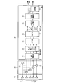
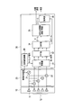
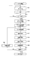
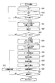
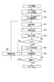
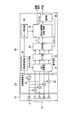
- FIG. 1 is a system diagram showing the configuration of a conventional radar apparatus
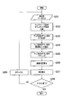
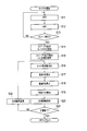
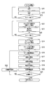
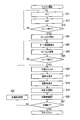
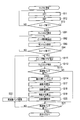
- FIG. 2 is a flowchart showing the operation of the radar apparatus.
- the radar apparatus includes an antenna 10, a transceiver 20 and a signal processor 30.
- the signal swept by the transmitter 21 inside the transceiver 20 is transmitted from the antenna transmission element 11.
- the signals received by the plurality of antenna receiving elements 12 are frequency-converted by the plurality of mixers 22 and sent to the signal processor 30.
- the beat frequency signal from the transmitter / receiver 20 is converted into a digital signal by the AD converter 31, and sent to the up sequence down sequence extraction unit 37 as an element signal (step S201).
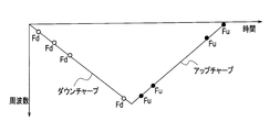
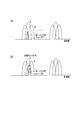
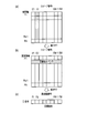
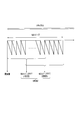
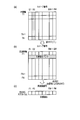
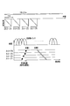
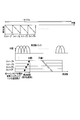
- FIGS. 3 and 4 show transmission / reception up-chirp and down-chirp sweep signals.
- the up-sequence down-sequence extraction unit 37 separates the up-chirp signal and the down-chirp signal from the element signal (digital signal) transmitted from the AD converter 31 and sends it to the FFT unit 33 (step S202).
- the FFT unit 33 performs fast Fourier transform on the up-chirp signal and the down-chirp signal sent from the up-sequence down-sequence extraction unit 37 to convert them into a signal on the frequency axis, and DBF (Digital Beam Forming) Send to part 34.
- DBF Digital Beam Forming
- the DBF unit 34 forms a ⁇ beam (up sequence and down sequence) and a ⁇ beam using the frequency-axis signal sent from the FFT unit 33 (step S203).
- the ⁇ beam formed by the DBF unit 34 is sent to the pairing unit 38, and the ⁇ beam is sent to the angle measuring unit 36.
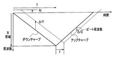
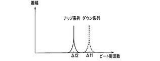
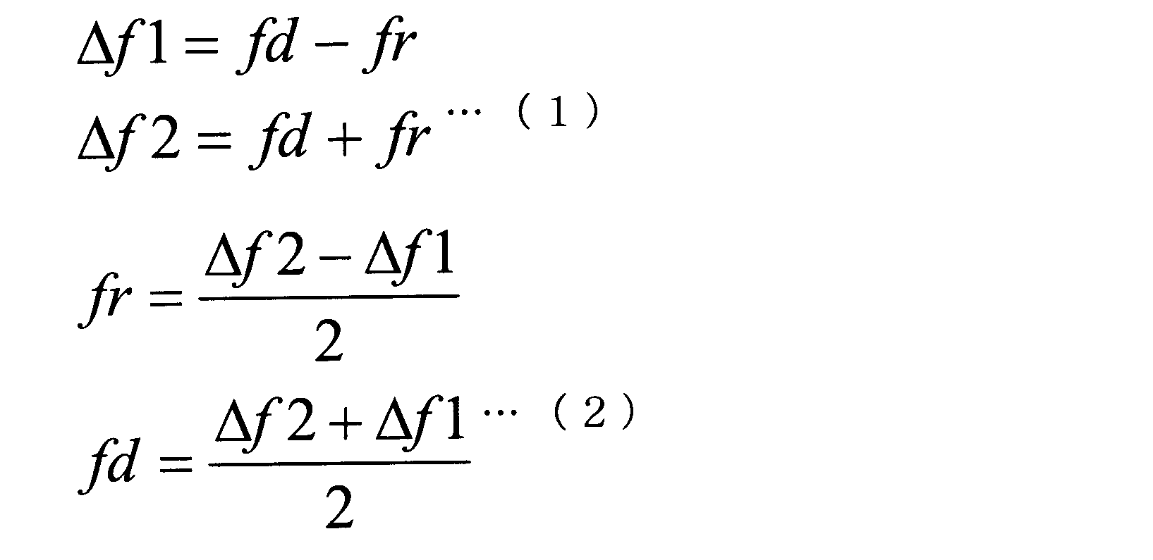
- the pairing unit 38 extracts a frequency having an extreme amplitude as shown in FIG. 5 based on the result of FFT of the up-sequence and down-sequence signals of the ⁇ beam (step S204). This relational expression is shown in the following expression.
- ⁇ f1 Observation frequency of down-chirp signal ⁇ f2; Observation frequency of up-chirp signal fd; Doppler frequency fr;
- B Frequency band R; Target distance T; Sweep time c; Light speed V; Target speed ⁇ ; Wavelength
- step S205 Up-sequence / down-sequence pairing is performed. That is, since the peak frequencies of the down chirp sequence and the up chirp sequence are different, processing for associating the frequency pair is performed.
- step S206 the target distance and speed are calculated (step S206), and the angle is calculated (step S207).
- step S208 it is checked whether or not the cycle is completed. If it is determined in step S208 that the cycle has not ended, processing for moving to the next cycle is performed (step S209). Thereafter, the process returns to step S201, and the above-described process is repeated. On the other hand, if the cycle ends in step S208, the processing of the radar device ends.
- the target distance R and speed V can be calculated by the above processing.
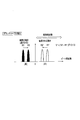
- the peak frequencies of the down-chirp sequence and the up-chirp sequence are different, it is necessary to correspond the frequency pair. Pairing is relatively easy in the case of a single goal or a minority goal.
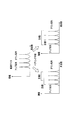
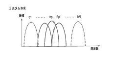
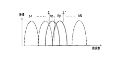
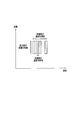
- the target number and the reflection point of the background increase, as shown in FIG. 6, there is a problem that the number of peak values on the frequency axis increases and pairing becomes difficult.
- the conventional radar apparatus has the following problems.
- An object of the present invention is to provide a radar apparatus that can observe a target with high detection performance and high accuracy even when a plurality of targets exist in a wide range from a short distance to a long distance.
- the first invention is a transmitter / receiver for transmitting an FMCW-modulated sweep signal M times, and a fast Fourier transform for M times of the sweep signal received in response to transmission from the transmitter / receiver.
- the beat frequency is calculated by the M sweep phase monopulse, amplitude monopulse or MUSIC.
- the result F (sweep number, target number) is used to perform amplitude integration in the sweep direction for each beat frequency on the beat frequency-sweep axis, and for each frequency bank that exceeds the predetermined threshold, the sweep that exceeds the predetermined threshold Calculate the least square line between the relative distance of the number and the sweep time, and set the target speed by the gradient of the least square line.
- a MRAV processing unit for calculating the distance of the target.
- a transceiver for transmitting an FMCW modulated sweep signal at least twice, an FFT unit for fast Fourier transforming at least two sweep signals received in response to transmission from the transceiver, and an FFT.
- the beat frequency corresponding to each of at least two sweeps by the transmitter / receiver is calculated based on at least two sweep signals obtained by performing Fourier transform in the unit, and the speed is calculated based on the calculated beat frequency difference and time difference.
- an MRAV processing unit that calculates distances and speeds of a plurality of targets by calculating a distance based on the calculated speed and beat frequency.
- a third invention includes a transceiver that transmits an FMCW-modulated sweep signal M times, an FFT unit that fast Fourier transforms M sweep signals received in response to transmission from the transceiver, and an FFT unit.
- the result F (sweep number, target) of the beat frequency calculated by the phase monopulse, amplitude monopulse or MUSIC of the M sweep
- an MRAV processing unit that calculates a distance after calculating the speed based on the smoothed result.
- a fourth invention includes a transceiver that transmits an FMCW-modulated sweep signal M times, an FFT unit that fast Fourier transforms M sweep signals received in response to transmission from the transceiver, and an FFT unit.
- the result F (sweep number, target) of the beat frequency calculated by the phase monopulse, amplitude monopulse or MUSIC of the M sweep MRAV processing unit that calculates the maximum value by Hough transform on the beat frequency-sweep axis using the number)
- the first invention by integrating the amplitude in the sweep direction for each beat frequency on the beat frequency-sweep axis, an integration effect between a plurality of sweeps is obtained to improve the signal detection performance.
- the distance is calculated after calculating the inclination of the straight line extracted by fitting with the least square line and calculating the velocity.
- the second invention it is not necessary to perform pairing in the case of a plurality of targets unlike the conventional radar apparatus, and radar observation with a short cycle time can be realized.
- the third invention since the speed and distance are calculated by smoothing between sweeps, even if there is an error in the relative distance difference, the influence of the error is reduced and the accuracy of speed measurement and distance measurement is improved. be able to.
- the fourth aspect of the invention by performing the Hough transform on the beat frequency-sweep axis, an integration effect between a plurality of sweeps is obtained to improve the signal detection performance. Also, the distance is calculated after calculating the speed by calculating the slope of the straight line extracted by the Hough transform. Thereby, even when there is an error in the relative distance difference, the influence of the error can be reduced and the accuracy of speed measurement and distance measurement can be improved.
- FIG. 1 is a system diagram showing a configuration of a conventional radar apparatus.
- FIG. 2 is a flowchart showing the operation of the conventional radar apparatus.
- FIG. 3 is a diagram showing transmission / reception signals of a conventional radar apparatus.
- FIG. 4 is a diagram showing transmission / reception signals of a conventional radar apparatus.
- FIG. 5 is a diagram for explaining processing of a conventional radar apparatus.
- FIG. 6 is a diagram for explaining the problems of the conventional radar apparatus.
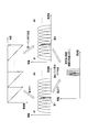
- FIG. 7 is a system diagram showing the configuration of the radar apparatus according to Embodiment 1 of the present invention.
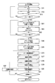
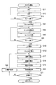
- FIG. 8 is a flowchart showing measurement processing performed by the radar apparatus according to Embodiment 1 of the present invention.
- FIG. 1 is a system diagram showing a configuration of a conventional radar apparatus.
- FIG. 2 is a flowchart showing the operation of the conventional radar apparatus.
- FIG. 3 is a diagram showing transmission / reception signals of a conventional radar apparatus.
- FIG. 4 is a diagram showing
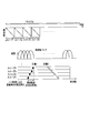
- FIG. 9 is a diagram for explaining a sweep signal performed by the radar apparatus according to Embodiment 1 of the present invention.
- FIG. 10 is a diagram for explaining how the beat frequency is extracted in the radar apparatus according to Embodiment 1 of the present invention.
- FIG. 11 is a diagram for explaining a processing process in the radar apparatus according to Embodiment 1 of the present invention.
- FIG. 12 is a diagram for explaining another process in the radar apparatus according to Embodiment 1 of the present invention.
- FIG. 13 is a flowchart showing a measurement process performed by the radar apparatus according to Embodiment 2 of the present invention.
- FIG. 14 is a diagram for explaining measurement processing performed by the radar apparatus according to Embodiment 2 of the present invention.
- FIG. 15 is a diagram for explaining the formation of ⁇ and ⁇ in the measurement process performed by the radar apparatus according to Embodiment 2 of the present invention.
- FIG. 16 is a diagram for explaining the calculation of the error voltage in the measurement process performed by the radar apparatus according to Embodiment 2 of the present invention.
- FIG. 17 is a diagram for explaining the calculation of the error voltage in the measurement process performed by the radar apparatus according to Embodiment 3 of the present invention.
- FIG. 18 is a diagram for explaining the calculation of the error voltage in the measurement process performed by the radar apparatus according to Embodiment 3 of the present invention.
- FIG. 19 is a flowchart showing a measurement process performed by the radar apparatus according to Embodiment 4 of the present invention.
- FIG. 20 is a mail diagram for explaining the measurement processing performed by the radar apparatus according to Embodiment 4 of the present invention.
- FIG. 21 is a system diagram showing a configuration of a radar apparatus according to Embodiment 5 of the present invention.
- FIG. 22 is a flowchart showing a measurement process performed by the radar apparatus according to Embodiment 5 of the present invention.
- FIG. 23 is a diagram for explaining measurement processing performed by the radar apparatus according to Embodiment 5 of the present invention.
- FIG. 24 is a diagram for explaining measurement processing performed by the radar apparatus according to Embodiment 5 of the present invention.
- FIG. 25 is a diagram for explaining measurement processing performed by the radar apparatus according to Embodiment 5 of the present invention.
- FIG. 21 is a system diagram showing a configuration of a radar apparatus according to Embodiment 5 of the present invention.
- FIG. 22 is a flowchart showing a measurement process performed by the radar apparatus according to Embodiment 5 of the present invention.
- FIG. 23 is
- FIG. 26 is a diagram for explaining measurement processing performed by the radar apparatus according to Embodiment 5 of the present invention.
- FIG. 27 is a diagram for explaining measurement processing performed by the radar apparatus according to Embodiment 5 of the present invention.
- FIG. 28 is a diagram for explaining measurement processing performed by the radar apparatus according to Embodiments 6 and 7 of the present invention.
- FIG. 29 is a flowchart showing a measurement process performed by a radar apparatus according to Embodiments 6 and 7 of the present invention.
- FIG. 30 is a diagram for explaining a measurement process performed by the radar apparatus according to Example 8 of the present invention.
- FIG. 31 is a flowchart showing a measurement process performed by the radar apparatus according to Embodiment 8 of the present invention.
- FIG. 32 is a flowchart showing a measurement process performed by the radar apparatus according to Embodiment 9 of the present invention.
- FIG. 33 is a diagram for explaining measurement processing performed by the radar apparatus according to Embodiment 9 of the present invention.
- FIG. 34 is a system diagram showing a configuration of a radar apparatus according to Embodiment 10 of the present invention.
- FIG. 35 is a diagram for explaining a sweep signal used in the radar apparatus according to Embodiment 10 of the present invention.
- FIG. 36 is a diagram for explaining a sweep signal used in the radar apparatus according to Embodiment 10 of the present invention.
- FIG. 37 is a system diagram showing a configuration of a radar apparatus according to Embodiment 11 of the present invention.
- FIG. 38 is a diagram for explaining a sweep signal used in the radar apparatus according to Embodiment 11 of the present invention.
- FIG. 39 is a flowchart showing processing performed by the radar apparatus according to Embodiment 11 of the present invention.
- FIG. 40 is a flowchart showing processing performed in the radar apparatus according to Embodiment 12 of the present invention.
- FIG. 41 is a diagram for explaining processing performed by the radar apparatus according to Embodiment 12 of the present invention.
- FIG. 42 is a diagram for explaining processing performed by the radar apparatus according to Embodiment 13 of the present invention.
- FIG. 43 is a flowchart showing processing performed by the radar apparatus according to Embodiment 13 of the present invention.
- FIG. 44 is a diagram for explaining processing performed in the radar apparatus according to Embodiment 14 of the present invention.
- FIG. 45 is a flowchart showing processing performed in the radar apparatus according to Embodiment 14 of the present invention.
- FIG. 46 is a diagram for explaining the Hough transform performed in the radar apparatus according to Embodiment 14 of the present invention.
- FIG. 47 is a diagram for explaining the Hough transform performed by the radar apparatus according to Embodiment 14 of the present invention.
- FIG. 48 is a diagram for explaining the Hough transform performed by the radar apparatus according to Embodiment 14 of the present invention.
- FIG. 49 is a diagram for explaining the Hough transform performed in the radar apparatus according to Embodiment 14 of the present invention.
- FIG. 50 is a diagram for explaining processing performed by the radar apparatus according to Embodiment 15 of the present invention.
- FIG. 51 is a flowchart showing processing performed in the radar apparatus according to Embodiment 15 of the present invention.
- the radar apparatus according to the present invention employs a simple system in which pairing is performed only between the same frequency bank or adjacent banks using a continuous FMCW signal that is easy to mount.
- the radar apparatus employs an MRAV (Measurement Range After Measurement Velocity) method of calculating a distance after calculating a velocity based on a beat frequency.
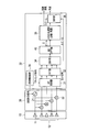
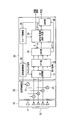
- FIG. 7 is a system diagram showing the configuration of the radar apparatus according to Embodiment 1 of the present invention.
- This radar apparatus includes an antenna 10, a transceiver 20, and a signal processor 30a.
- the antenna 10 includes an antenna transmitting element 11 and a plurality of antenna receiving elements 12.
- the antenna transmission element 11 converts a transmission signal sent as an electrical signal from the transceiver 20 into a radio wave and sends it out.
- the plurality of antenna receiving elements 12 receive external radio waves, convert them into electrical signals, and send them to the transceiver 20 as received signals.
- the transceiver 20 includes a transmitter 21 and a plurality of mixers 22, and the plurality of mixers 22 are provided corresponding to the plurality of antenna receiving elements 12, respectively.
- the transmitter 21 generates a transmission signal in accordance with the transmission control signal sent from the signal processor 30 and sends it to the antenna transmission element 11 and the plurality of mixers 22.
- the plurality of mixers 22 frequency-convert the received signals received from the plurality of antenna receiving elements 12 in accordance with the signals from the transmitter 21 and send the signals to the signal processor 30.
- the signal processor 30a includes an AD converter 31, an FFT unit 32, a DBF unit 34, an MRAV processing unit 35a, an angle measuring unit 36, and a transmission / reception control unit 39.
- the AD converter 31 converts the analog signal sent from the transmitter / receiver 20 into a digital signal according to the timing signal sent from the transmission / reception control unit 39, and sends it to the FFT unit 32 as an element signal.
- the FFT unit 32 converts the element signal sent from the AD converter 31 into a signal on the frequency axis by fast Fourier transform, and sends it to the DBF unit 34.
- the DBF unit 34 uses the signals on the frequency axis sent from the FFT unit 33 to form a ⁇ beam and a ⁇ beam.
- the ⁇ beam formed by the DBF unit 34 is sent to the MRAV processing unit 35a, and the ⁇ beam is sent to the angle measuring unit 36.
- the MRAV processing unit 35a performs ranging and speed measurement based on the ⁇ beam from the DBF unit 34.
- the distance and speed obtained by the distance measurement and speed measurement in the MRAV processing unit 35a are output to the outside.
- the angle measuring unit 36 performs angle measurement based on the ⁇ beam sent from the DBF unit 34.
- the angle obtained by the angle measurement by the angle measuring unit 36 is output to the outside.
- the transmission / reception control unit 39 generates a transmission control signal for starting transmission and sends the transmission control signal to the transmitter 21 of the transmitter / receiver 20, and generates a timing signal that defines the timing for capturing the signal from the transmitter / receiver 20 to perform AD conversion. Send to vessel 31.
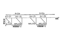
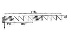
- a sweep 1 that is a frequency-changed sweep signal, that is, an FM-modulated sweep signal, is transmitted from the antenna transmission element 11 and transmitted as shown in FIG.
- the received signal is received by the antenna receiving element 12.
- the received signal is frequency-converted by the transmitter / receiver 20 and sent to the AD converter 31 of the signal processor 30a.
- the AD converter 31 converts the analog signal sent from the transceiver 20 into a digital signal.
- signals of N samples corresponding to each of the time axes T1 to TN are obtained for the elements having the element numbers E1 to EM of the antenna receiving element 12.
- the signal obtained by the AD converter 31 is sent to the FFT unit 32 as an element signal.
- step S11 fast Fourier transform
- the FFT unit 32 performs a fast Fourier transform on the element signal sent from the AD converter 31.
- a signal is obtained.
- the beat frequency signal obtained by the FFT unit 32 is sent to the DBF unit 34.
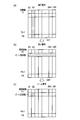
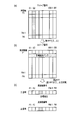
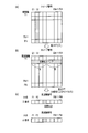
- step S12 DBF processing is performed (step S12). That is, the DBF unit 34 forms a ⁇ beam and a ⁇ beam in the angle direction using the signal on the frequency axis sent from the FFT unit 33. Thereby, as shown in FIG.11 (c), the beam which has a peak in a specific beam number (for example, B2) is formed.
- the ⁇ beam formed by the DBF unit 34 is sent to the MRAV processing unit 35, and the ⁇ beam is sent to the angle measuring unit 36.
- step S13 it is determined whether or not the sweep is finished (step S13). That is, it is checked whether or not the processing for both sweep 1 and sweep 2 has been completed. If the sweep has not ended in step S13, the process returns to step S11, and the above-described process is repeated for sweep 2 that is the next FM-modulated sweep signal.
- step S14 threshold detection of sweep 1 and sweep 2 is performed (step S14). That is, the DBF unit 34 detects the threshold level of the ⁇ beam obtained by the sweep 1 and the sweep 2.
- step S15 the target detected in step S14 is stored (step S15). That is, the DBF unit 34 detects and stores the target from the threshold level detected in step S14.
- the beat frequency is extracted (step S16). That is, as shown in FIG. 10, the MRAV processing unit 35a extracts the beat frequency fp having a peak signal and the bank signal based on the FFT and DBF results of the sweep 1 and the sweep 2.
- an angle ⁇ is calculated (step S19). That is, the angle measuring unit 36 performs angle measurement based on the ⁇ beam sent from the DBF unit 34 and outputs the angle obtained by this angle measurement to the outside.
- step S20 the target information is stored (step S20). That is, the target speed V, distance R, and angle ⁇ calculated in step S17 are stored.
- step S21 it is checked whether or not the goal is finished (step S21). That is, it is checked whether or not the processing for all the targets has been completed.
- step S21 when the target has not ended, the target number is changed to the next number, and the process returns to step S16 and the above-described processing is repeatedly executed. On the other hand, if the target is finished in step S21, the measurement process is finished.
- the radar apparatus in order to transmit / receive an up-chirp or down-chirp sequence signal, pairing in the case of multiple beat targets having the same beat frequency is performed. There is no need to do. Also, radar observation with a short cycle time can be realized.
- the radar apparatus performs digital beam forming (DBF) after performing fast Fourier transform (FFT) to obtain the beat frequency.
- DBF digital beam forming
- FFT fast Fourier transform
- the radar apparatus according to the second embodiment of the present invention employs a method in which a phase monopulse is combined with the MRAV method according to the first embodiment described above.
- the configuration of the radar apparatus according to the second embodiment is the same as the configuration of the radar apparatus according to the first embodiment illustrated in FIG.
- FIG. 13 is a flowchart showing the operation of the radar apparatus according to the second embodiment of the present invention, centering on measurement processing for performing distance measurement / speed measurement and angle measurement.
- symbol used in FIG. 8 is attached
- portions different from the first embodiment will be mainly described.
- the radar apparatus observes the frequency in the bank with high accuracy using the phase monopulse used on the angle axis as the frequency axis as shown in FIGS.
- the phase monopulse (sometimes referred to as phase comparison monopulse) is described in “Supervised by Takashi Yoshida,“ Revised Radar Technology ”, IEICE, pp.274-275 (1996)”.
- an error voltage ⁇ p of the following equation is calculated using ⁇ (f) and ⁇ (f) of the extracted target frequency.
- the phase monopulse processing is performed by the FFT unit 32.
- ⁇ Addition (Received data 1 to N multiplied by weighting 1 and then FFT)
- ⁇ Subtraction (1 to N / 2 of received data is multiplied by -1 and N / 2 + 1 to N is multiplied by weighting 1 and then FFT) *; Complex conjugate Re; Real part
- the reference value ⁇ 0 of the error voltage ⁇ p calculated using the frequency characteristics of ⁇ and ⁇ stored in advance is tabulated (corresponding to ⁇ 0 and frequency f).
- the beat frequency fp is extracted from the observed value ⁇ (step S16). Then, the speed and distance are calculated using the extracted beat frequency fp (steps S17 and S18).
- weights such as tailor weights based on tailor distribution may be multiplied in order to reduce side lobes.
- the Taylor distribution is described in, for example, “Supervised by Takashi Yoshida,“ Revised Radar Technology ”, IEICE, pp.274-275 (1996)”.
- the beat frequency of each sweep signal is calculated with high accuracy based on the phase monopulse error voltage. It can be calculated with high accuracy.
- the radar apparatus according to the third embodiment of the present invention uses an amplitude comparison monopulse instead of the phase monopulse of the radar apparatus according to the second embodiment.
- the configuration of the radar apparatus according to the third embodiment is the same as the configuration of the radar apparatus according to the first embodiment illustrated in FIG. Hereinafter, portions different from the first embodiment will be mainly described.
- the amplitude comparison monopulse (also called amplitude monopulse) is described in “Supervised by Takashi Yoshida,“ Revised Radar Technology ”, IEICE, pp.274-275 (1996)”.
- ⁇ Addition (FFT after multiplying received data 1 to N by weighting 1) ⁇ u; the larger absolute value of (f ⁇ 1) and ⁇ (f + 1), and the error voltage ⁇ p calculated using the frequency characteristics of the absolute values abs ( ⁇ ) and absolute values abs ( ⁇ u) stored in advance
- the reference value ⁇ 0 is tabulated (correspondence between ⁇ 0 and frequency f).
- the beat frequency value fp is extracted based on the observed value ⁇ using the reference table. The speed and distance are calculated using the extracted beat frequency fp.
- the beat frequency of each sweep signal is calculated with high accuracy based on the amplitude monopulse error voltage. Can be calculated with high accuracy.
- a weight such as a tailor weight may be multiplied to reduce the side lobes in addition to ⁇ 1 or 1 as in the radar apparatus according to the second embodiment described above.
- the radar apparatus employs the MUSIC method.
- the MUSIC method is described in “HARRY B.LEE,“ Resolution ”Threshold of Beams“ pace ”MUSIC“ For ”Two“ Closely ”Spaced“ Emitters ”,“ IEEE ”Trans.“ ASSP, ”Vol. 38,“ No. 9, “Sept.” (1990) .
- FIG. 19 is a flowchart illustrating the operation of the radar apparatus according to the fourth embodiment of the present invention, centering on measurement processing for performing distance measurement / speed measurement and angle measurement.
- the same reference numerals as those used in FIG. 7 are given to steps for performing the same or corresponding processing as the measurement processing according to the first embodiment shown in the flowchart of FIG. 8. .
- portions different from the first embodiment will be mainly described.
- the FFT unit 32 performs a fast Fourier transform on the sweep signal
- a bank signal of ⁇ M is extracted around the maximum value bank of the ⁇ signal
- the beat frequency is calculated with high accuracy by applying the beam space type MUSIC.
- This radar apparatus calculates the speed based on the beat frequency difference (distance difference) twice and the time difference, and further calculates the absolute distance based on the beat frequency and the speed, thereby calculating the distance and speed of Nt targets. calculate.
- the beam can be expanded on the frequency axis such as fast Fourier transform (FFT).
- FFT fast Fourier transform
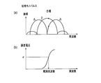
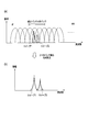
- the procedure is as follows. That is, as shown in FIG. 20A, a target bank whose amplitude exceeds a predetermined threshold is extracted based on the result of the fast Fourier transform (FFT). Then, a correlation matrix Rbb is calculated from ⁇ M banks (2M + 1) of complex signals Xm around the extracted target bank.
- FFT fast Fourier transform
- Rbb Correlation matrix
- X Column vector having elements XM to X0 to XM (2M + 1)
- H Complex conjugate transposition
- the eigenvector Eb of Rbb of the correlation matrix is calculated.
- an eigenvector EN for noise is extracted from the eigenvector Eb.
- the MUSIC spectrum is calculated by the following equation. As shown in FIG. 20 (b), the beat frequency fp having an extreme value in the spectrum is read.
- ws steering column vector having element ws (n) on the time axis
- fs search frequency PRF: repetition frequency n: 1 to N (N is the number of samples)
- EN Eigenvector of correlation matrix
- Rbb H Conjugate transposition
- the beat frequency of each sweep signal is calculated with high accuracy based on the FFT and MUSIC processing. Can be calculated with high accuracy.
- FIG. 21 is a block diagram showing a configuration of a radar apparatus according to Embodiment 5 of the present invention.
- This radar apparatus is configured by adding a second FFT section 40 between the DBF section 34 and the MRAV processing section 35 in the signal processor 30a of the radar apparatus shown in FIG.
- the second FFT unit 40 performs a fast Fourier transform on the signal output from the DBF unit 34.
- a method of integrating between a plurality of sweeps is adopted in order to further improve the SN ratio and improve the frequency resolution within the restriction of the frequency band. Has been.
- This radar device transmits an FMCW-modulated sweep signal N times (# 1 to #N), and extracts the local maximum value of the Nt point from the result of the fast Fourier transform of each sweep.
- the radar apparatus performs two M sweeps by extracting a bank of local maximum values from FFT signals of # 1 to # N1 (M sweep) and # N2 to #N (M sweep) sweeps.
- the beat frequency of the bank signal having the maximum value among the results of each fast Fourier transform is calculated.
- the radar apparatus calculates the speed based on the two beat frequency differences (distance difference) and the time difference, and calculates the absolute distance based on the beat frequency and the speed, thereby calculating the distance and speed of the Nt targets. To do.
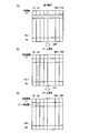
- FIG. 27 shows the state of each FFT in the two M sweeps.
- a second M-sample FFT is performed.
- the first FFT unit 32 calculates ⁇ (difference between 1 to N / 2 and N / 2 + 1 to N) in addition to the sum ⁇ of N samples.
- a ⁇ and ⁇ signal by two-stage FFT is obtained by calculating the sum of ⁇ and ⁇ of M samples as a result of the first FFT. Thereafter, a phase monopulse calculation may be performed to calculate a highly accurate frequency fp.
- FIG. 22 is a flowchart showing the operation of the radar apparatus according to the fifth embodiment of the present invention, centering on measurement processing for performing distance measurement / speed measurement and angle measurement.
- the same reference numerals as those used in FIG. 8 are given to steps for performing the same or corresponding processes as the measurement process according to the first embodiment shown in the flowchart of FIG. 8. In the following, a description will be given centering on differences from the first embodiment.
- N sweeps are transmitted and received, and the first FFT is executed by the FFT unit 32 for each sweep (steps S11 to S13).
- a target bank exceeding a predetermined threshold is extracted (step S51).
- the target bank of each sweep is subjected to a second FFT by the second FFT unit 39 (step S52).
- the peak beat frequency fp is read.
- speed calculation (step S17) and distance calculation (step S18) are performed using the calculated beat frequency fp.
- N sweeps are transmitted and received, and the first FFT is executed by the FFT unit 32 for each sweep (steps S11 to S13).
- the ⁇ signal and the ⁇ signal are calculated, and a target bank in which the absolute value of the ⁇ signal exceeds a predetermined threshold is extracted (step S51).
- the ⁇ signal and ⁇ signal of the target bank of each sweep are subjected to a second FFT by the second FFT unit 40 (step S52).
- the frequency fp is calculated using the ⁇ signal and the ⁇ signal, and the distance and the speed are calculated using the calculated frequency fp.
- the extracted bank signal of each sweep signal is further subjected to the second FFT between sweeps, so that the resolution is higher than that of the bank using only the first FFT.
- the target position and speed can be extracted.
- FIG. 29 is a flowchart showing the operation of the radar apparatus according to Embodiment 6 of the present invention, centering on measurement processing for measuring distance / speed measurement and angle measurement.
- the same reference numerals as those used in FIG. 22 are assigned to steps that perform the same or corresponding processes as the measurement process according to the fifth embodiment shown in the flowchart of FIG. In the following, a description will be given centering on differences from the fifth embodiment.
- N sweeps are transmitted and received, and FFT is executed for each sweep (steps S11 to S13).
- a target bank whose amplitude exceeds a predetermined threshold is extracted (step S51).
- ⁇ and ⁇ are calculated by the second FFT unit 40 using the target banks E1 to EM extracted in step S51.
- an error voltage ⁇ p of the following equation is calculated using ⁇ (f) and ⁇ (f) of the extracted target frequency.
- ⁇ Addition (FFT after multiplying E1 to EM by weight 1)
- ⁇ Subtraction (E1 to EM / 2 multiplied by ⁇ 1, EM / 2 + 1 to EM weighted by 1 and then FFT) *; Complex conjugate Re; Real part
- the reference value ⁇ 0 of the error voltage ⁇ p calculated using the frequency characteristics of ⁇ and ⁇ stored in advance is tabulated (corresponding to ⁇ 0 and the frequency f).
- the frequency value fp is extracted based on the observed value ⁇ (step S16).
- speed calculation step S17
- distance calculation step S18
- the beat frequency is calculated with high accuracy by calculating the frequency using the phase monopulse.
- the target position and speed can be extracted with high accuracy.
- a weight such as a tailor weight may be multiplied to reduce the side lobes in addition to ⁇ 1 or 1 as in the radar apparatus according to the second embodiment described above.
- N sweeps are transmitted and received, and the first FFT is executed for each sweep (steps S11 to S13).
- a target bank whose amplitude exceeds a predetermined threshold is extracted (step S51).
- the absolute value abs ( ⁇ (f ⁇ 1)) and the absolute value abs ( ⁇ (F + 1)) are compared, and the larger one is set as the absolute value abs ( ⁇ u).
- ⁇ Addition (FFT after multiplying received data 1 to N by weighting 1) ⁇ u; the larger absolute value of ⁇ (f ⁇ 1) and ⁇ (f + 1), and the reference value of the error voltage ⁇ p calculated using the frequency characteristics of abs ( ⁇ ) and abs ( ⁇ u) stored in advance ⁇ 0 is tabulated (corresponding to ⁇ 0 and frequency f).
- the beat frequency value fp is extracted based on the observed value ⁇ using the reference table. The distance and speed are calculated using the calculated beat frequency fp.
- the beat frequency is calculated with high accuracy by calculating the frequency using the amplitude monopulse.
- the target position and speed can be extracted with high accuracy.
- a weight such as a tailor weight may be multiplied by a weight other than ⁇ 1 or 1 in order to reduce the side lobe, similarly to the radar apparatus according to the second embodiment described above.
- the radar apparatus according to Example 8 of the present invention calculates the beat frequency by FFT and MUSIC processing of M sweep when calculating each local maximum value from two M sweep signals. .
- FIG. 31 is a flowchart showing the operation of the radar apparatus according to the eighth embodiment of the present invention, centering on measurement processing for measuring distance / speed measurement and angle measurement.
- the same reference numerals as those used in FIG. 22 are given to steps for performing the same or corresponding processes as the measurement process according to the fifth embodiment shown in the flowchart of FIG. 22. In the following, a description will be given centering on differences from the fifth embodiment.
- a target bank whose amplitude exceeds a predetermined threshold is extracted based on the result of FFT in steps S11 to S13 (step S51).
- a correlation matrix Rbb is calculated based on the complex signal Xm for M sweeps of the target bank.
- Rbb Correlation matrix
- X Column vector having elements X1 to XM (M) H: Complex conjugate transposition
- an eigenvector Eb of the correlation matrix Rbb is calculated.
- an eigenvector EN for noise in the eigenvector Eb is extracted, a MUSIC spectrum is calculated by the following equation using the eigenvector EN and a steering vector w for searching for a frequency, and the beat frequency at which the spectrum has an extreme value is calculated.
- fp is read. This MUSIC process is performed by the second FFT unit 39 (step S71).
- Rbb H Conjugate transposition
- the frequency is calculated by the FFT and MUSIC processing, so that the beat can be accurately performed.
- the frequency can be extracted, and the target position and speed can be extracted with high accuracy.
- the radar apparatus When the sweep signal is a real signal (not a complex signal), the radar apparatus according to Embodiment 9 of the present invention extracts a positive (or negative) signal from the beat frequency by performing a complex Fourier transform on the sampled signal. Thus, a complex signal is obtained. In this case, depending on the distance and speed, the target is actually observed as positive (or negative) even if the beat frequency is negative (or positive), and therefore the distance and speed may be wrong. In this case, it can be determined that the beat frequency is negative (positive) based on the following principle.
- FIG. 32 is a flowchart showing the operation of the radar apparatus according to Embodiment 9 of the present invention, centering on measurement processing for measuring distance / speed measurement and angle measurement.
- the same reference numerals as those used in FIG. 8 are assigned to steps that perform the same or corresponding processes as the measurement process according to the first embodiment shown in the flowchart of FIG. In the following, a description will be given centering on differences from the fifth embodiment.
- the negative velocity observation method by the MRAV method is performed by the following procedure. After the distance difference between the two sweeps is observed, the target velocity V is calculated based on the position change and time (step S17). Next, the distance R is calculated from the beat frequency using the target speed V calculated in step S17 (step S18). Next, the angle ⁇ is calculated (step S19). Next, it is checked whether or not the distance R is negative (step S61). If the distance R is negative in step S61, the sign inversion unit (not shown) inverts the signs of the distance R, the speed V, and the angle ⁇ (step S62). On the other hand, if the distance R is not negative in step S61, the process of step S62 is skipped.
- the radar apparatus when a real sampling frequency is subjected to complex Fourier transform and only a positive (or negative) beat frequency is observed, a true target signal is obtained. Even when the beat frequency has a negative (or positive) beat frequency, the correct sign can be determined based on the calculated sign of the distance and converted to the correct sign of the distance, speed, and angle.
- the radar apparatus according to Example 10 of the present invention employs the method adopted in Example 1 or Example 2 when the observation target exists in a wide range from a short distance to a long distance and the speed range is wide.
- FIG. 34 is a system diagram showing a configuration of a radar apparatus according to Embodiment 10 of the present invention.
- This radar apparatus is configured by adding a sweep control unit 41 to the radar apparatus according to the first embodiment.
- the sweep control unit 41 sends to the transmission / reception control unit 39 and the MRAV processing unit 35a a control signal for transmitting a signal in which the gradient of the sweep signal is increased at a short distance and the gradient of the sweep signal is decreased at a long distance. Control these.
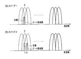
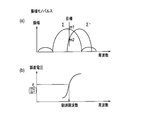
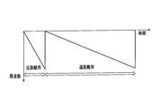
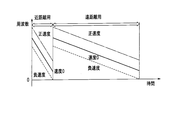
- the transmission signal In the case of a short-distance target, the transmission signal is in the vicinity of DC on the beat frequency axis after the FFT, and is susceptible to noise due to the wraparound of the transmission signal to the reception side.
- the separation frequency increases from the DC component and is not easily affected by noise. For this reason, as shown in FIGS. 35 and 36, the transmission / reception signals are divided into short distance and long distance, and the frequency gradient is increased at the short distance and the frequency gradient is decreased at the long distance.
- the band B and the PRF are the same, the number of points decreases at a short distance.
- the effect of reducing noise is greater than the signal integration effect, and the required S / N ratio can be ensured. Since the number of points is large at a long distance, the signal integration effect is high and the required S / N ratio can be ensured.
- Signal can be transmitted and received, and radar observation at a high S / N ratio can be realized.
- FIG. 38 shows an example of a plurality of transmission / reception sweep signals for short distance and long distance.
- FIG. 37 is a system diagram showing a configuration of a radar apparatus according to Embodiment 11 of the present invention.
- This radar apparatus is configured such that an angle signal is sent from the angle measuring section 36 of the radar apparatus according to the tenth embodiment to the sweep control section 38.
- a high weight may be given to a target having a large relative speed that is approaching at a close distance, and can be expressed by the following equation.
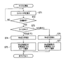
- FIG. 39 is a flowchart showing a procedure for selecting the optimum sweep interval (sweep number) using this risk level.
- Cr k (constant) ⁇ V / R is calculated for each target (steps S71 and S72).
- the maximum value is extracted if it is positive, and the minimum value is extracted if it is negative (steps S74 and S76).
- a sweep is selected so as to maximize the target observation accuracy corresponding to the extracted Cr (steps S75 and S76).
- the sweep Ts (or the sweep number close to Ts) may be selected by the following equation.
- the time between sweeps is shorter when the target speed is fast, and longer when the target speed is slow. Therefore, when the target speed is unknown, it is possible to select an optimum sweep corresponding to the target by determining the target whose speed accuracy is to be increased using the degree of risk.
- the radar apparatus according to Embodiment 12 of the present invention is such that different sweeps are periodically changed for each cycle.
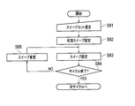
- FIG. 40 is a flowchart illustrating processing of the radar apparatus according to the twelfth embodiment. This process is performed by the sweep control unit 38.
- step S81 a sweep set is selected (step S81).
- step S82 an initial sweep is set (step S82).
- step S83 a sweep is set (step S83).
- step S84 it is checked whether or not the cycle is completed (step S84).
- step S84 if the cycle has not ended, the sweep is changed (step S85). Then, it returns to step S83 and the process mentioned above is repeated. On the other hand, if the cycle ends in step S84, the process ends, and the process proceeds to the next cycle.
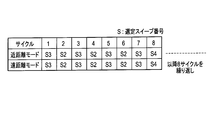
- FIG. 41 is a diagram showing an example of a cycle.
- the sweep number is selected by repeating eight cycles of S3-S2-S3-S2-S3-S2-S3-S4.
- the speed and distance accuracy can be improved for any target by periodically changing different sweeps for each cycle.
- the radar apparatus according to Embodiment 13 of the present invention obtains a smoothing effect by using M multiple sweep signals.
- the configuration of the radar apparatus according to Embodiment 13 is the same as that of the radar apparatus according to Embodiment 10 shown in FIG.
- FIG. 43 is a flowchart illustrating processing of the radar apparatus according to the thirteenth embodiment.
- the beat frequency fp is calculated by the M sweep phase monopulse (amplitude monopulse, MUSIC) (steps S91 to S94), and the equation (5) is used.
- the result converted into the relative distance is R (m, n) (sweep number m, target number n).
- step S95 Smoothing is performed by a smoothing filter between S (m, n) sweeps (step S95), and the speed is calculated based on the result, and then the relative distance is calculated (steps S17 to S18).
- the processing of steps S91 to S94, step S95, and steps S17 to S18 is performed by the MRAV processing unit 35.
- v speed T1M: time interval of sweep 1
- M fp beat frequency
- ⁇ wavelength
- B band T: sweep time
- the smoothing filter only needs to obtain a smoothing effect, such as a least square filter, Other filters can also be used.
- the first and M-th sweeps are used, but other sweep intervals may be used as long as a smoothing effect can be obtained.
- the relative distance difference for calculating the speed is observed by a plurality of sweeps (a plurality of times) and smoothed. Therefore, even if there is an error in the relative distance difference, the influence of the error can be reduced, and the accuracy of speed measurement and distance measurement can be improved.
- the MRAV method described above depends on the accuracy of the relative distance difference (beat frequency) between two sweeps. For this reason, when the SN ratio is small, the speed and distance may be deteriorated.
- the radar apparatus according to Embodiment 14 of the present invention obtains an integration effect using Hough transform using M multiple sweep signals, and performs smoothing. It is an effect.
- the configuration of the radar apparatus according to Embodiment 14 is the same as that of the radar apparatus according to Embodiment 10 shown in FIG.
- FIG. 45 is a flowchart illustrating processing of the radar apparatus according to the fourteenth embodiment.
- the beat frequency fp is calculated by the M sweep phase monopulse (amplitude monopulse, MUSIC), and F (sweep number m, target number n) and (Steps S92 to S94).
- Vp (RM-R1) / (TM-T1) here, R1, RM: Relative distance corresponding to sweep 1 and sweep M on the straight X axis (beat frequency axis) T1, TM: Time of the start point of sweep 1 and sweep M Next, using beat frequency fp and velocity Vp, The distance is calculated by the following equation (step S18).
- the processes of steps S92 to S94, steps S101 to S102, and steps S17 to S18 are performed by the MRAV processing unit 35.
- Vp Velocity fp: Beat frequency ⁇ : Wavelength B: Band T: Sweep time Note that the beat frequency axis-sweep axis was used when performing the Hough transform, but the beat frequency is relative using equation (5). After conversion to distance, Hough transform may be used on the relative distance-sweep axis.
- the Hough transform is a technique for extracting a straight line from an image.
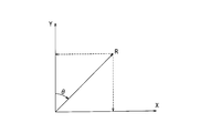
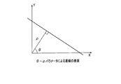
- a straight line on the XY plane is expressed in polar coordinates, as shown in FIGS. 46 and 47, the following equation is obtained.
- the straight line and ⁇ , ⁇ correspond uniquely.
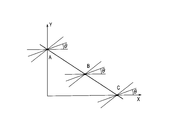
- three points A, B, and C on the straight line are considered.
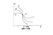
- a curve when the angle ⁇ is changed in order through each point is represented by the ⁇ - ⁇ axis as shown in FIG.
- the three curves intersect at a certain point, and this point ( ⁇ 0, ⁇ 0) represents a common straight line on the XY axis.
- the relative distance difference for calculating the speed is observed in a plurality of sweeps (a plurality of times), and the relative distance difference-the sweep time is on the axis.
- the Hough transform By performing the Hough transform, the integration effect between a plurality of sweeps is obtained and the signal detection performance is improved.
- the speed is calculated, and then the distance is calculated to reduce the influence of the error even if there is an error in the relative distance difference. The accuracy of distance measurement can be improved.
- the radar apparatus according to Embodiment 15 of the present invention obtains an integration effect by performing amplitude integration using M multiple sweep signals, and also provides a smoothing effect. Is obtained.
- the configuration of the radar apparatus according to Embodiment 15 is the same as that of the radar apparatus according to Embodiment 10 shown in FIG.
- FIG. 51 is a flowchart illustrating processing of the radar apparatus according to the fifteenth embodiment.
- the beat frequency fp (corresponding to the relative distance Rp according to the equation (5)) is obtained from the M sweep phase monopulse (amplitude monopulse, MUSIC). Calculated and set to F (sweep number m, target number n) (steps S92 to S94).
- amplitude integration (video integration) is performed for each frequency bank from the beat frequency-sweep axis using F (m, n) (step S111), and a frequency bank fb exceeding a predetermined threshold is extracted (step S111). Step S112).
- the least square line between the sweep time m and the relative distance Rp which can be expressed by the following equation, is calculated for the frequency bank fb by the sweep F (m, n) exceeding the threshold (step S114).
- the speed is calculated from the gradient of the power line (step S17).
- step S18 using the beat frequency fp and the velocity Vp, the distance is calculated by the following equation (step S18).
- steps S92 to S94, steps S111 to 114, and steps S17 to S18 are performed by the MRAV processing unit 35.
- Vp speed fp: beat frequency ⁇ : wavelength B: band T: sweep time
- fp speed fp: beat frequency
- ⁇ wavelength
- fp used in the equation (19) an average value or the like in each sweep may be used.
- the relative distance difference for calculating the speed is observed in a plurality of sweeps (a plurality of times), and the relative distance difference-the sweep time is on the axis.
- the distance is calculated after calculating the speed by calculating the slope of the extracted straight line by fitting with the least square line.
- the present invention can be used in a radar device that measures the distance to a vehicle and the speed of the vehicle.
Landscapes
- Engineering & Computer Science (AREA)
- Radar, Positioning & Navigation (AREA)
- Remote Sensing (AREA)
- Computer Networks & Wireless Communication (AREA)
- Physics & Mathematics (AREA)
- General Physics & Mathematics (AREA)
- Radar Systems Or Details Thereof (AREA)
Abstract
Provided is a device equipped with a transceiver (20) whereby sweep signals subjected to FMCW modulation is transmitted at least twice, an FFT unit (32) whereby at least two rounds of sweep signals received in response to transmission from the transceiver are subjected to fast Fourier transforms, and an MRAV processing unit (35a) whereby beat frequencies corresponding to each of the at least two rounds of sweeps by the transceiver are calculated on the basis of at least two rounds of sweep signals obtained by performing Fourier transforms in the FFT unit, whereby velocities are calculated on the basis of beat frequency differences and time differences that are calculated, and whereby distances are calculated on the basis of velocities and beat frequencies that are calculated, thereby making calculations of distances and velocities of a plurality of targets.
Description
本発明は、FMCW(Frequency Modulated Continuous Wave)方式により車両の距離と速度を観測するレーダ装置に関する。
The present invention relates to a radar apparatus that observes the distance and speed of a vehicle by an FMCW (Frequency-Modulated-Continuous Wave) method.
道路を走行する車両をレーダ装置で観測する場合の簡易なレーダ方式としてFMCW方式が知られている(例えば、非特許文献1参照)。このFMCW方式が採用されたレーダ装置の場合、距離と速度が未知数となる。このため、送受信波形としては、一般に、アップチャープとダウンチャープとを組み合わせることにより、2個のパラメータが同時に算出される。
The FMCW method is known as a simple radar method for observing a vehicle traveling on a road with a radar device (for example, see Non-Patent Document 1). In the case of a radar apparatus employing this FMCW method, the distance and speed are unknown. For this reason, as a transmission / reception waveform, two parameters are generally calculated simultaneously by combining up-chirp and down-chirp.
ただし、アップチャープとダウンチャープとで送受信した信号のビート周波数軸では、目標が同じでも周波数が異なる。このため、単一目標のみが存在する場合には対応をとることができる。しかしながら、複数目標が存在する場合には、各目標毎にアップチャープとダウンチャープとのペアリングが困難になるという問題がある。また、アップチャープとダウンチャープを送受信する必要があるため、サイクルタイムが長くなるという問題がある。
However, on the beat frequency axis of signals transmitted and received between up-chirp and down-chirp, the frequency is different even if the target is the same. For this reason, when only a single target exists, a response can be taken. However, when there are multiple targets, there is a problem that it is difficult to pair up-chirp and down-chirp for each target. Further, since it is necessary to transmit and receive up-chirp and down-chirp, there is a problem that the cycle time becomes long.
また、距離分解能に関する周波数帯域に制約がある場合、または、角度分解能に関するアンテナ開口長に制約がある場合には、密集目標の分離性能に制約が生じるという問題がある。
Also, when there is a restriction on the frequency band related to the distance resolution, or when there is a restriction on the antenna aperture length related to the angular resolution, there is a problem that the separation performance of the dense target is restricted.
これらの問題の他に、積分数Nが少ないと、同一PRF(Pulse Repetition Frequency:パルス繰り返し周波数)の場合には、信号をFFT(Fast Fourier Transform:高速フーリエ変換)した後のビート周波数軸の各周波数バンク幅(PRF/N)が大きくなって周波数分解能が劣化し、その周波数に基づいて算出される距離や速度の精度が劣化するという問題がある。
In addition to these problems, if the integral number N is small, in the case of the same PRF (Pulse Repetition Frequency), each beat frequency axis after FFT (Fast Fourier Transform) of the signal The frequency bank width (PRF / N) becomes large and the frequency resolution deteriorates, and there is a problem that the accuracy of distance and speed calculated based on the frequency deteriorates.
また、実数信号が複素フーリエ変換され、正(または負)の周波数のみが抽出されることにより複素信号が抽出される場合に、目標ビート周波数の正しい符号が負(または正)であるときには、正しい距離、速度および角度を算出できないという問題がある。
In addition, when a complex signal is extracted by performing a complex Fourier transform on a real signal and only a positive (or negative) frequency is extracted, it is correct when the correct sign of the target beat frequency is negative (or positive). There is a problem that distance, speed and angle cannot be calculated.
また、近距離ではビート周波数が直流(周波数が0)成分に近くなるために周波数勾配(周波数帯域B/スイープ時間T)を大きくすることにより、近距離であってもビート周波数を直流から離隔した周波数にする必要がある。この場合、周波数帯域Bとサンプル周波数PRFに制約がある場合には、積分数Nを大きくできないという問題がある。特に、遠距離目標を観測する場合には、積分数が少なくなると、SN比(信号/雑音比)が小さくなるため、検出性能や精度が劣化する。
Further, since the beat frequency is close to a direct current (frequency is 0) component at a short distance, the beat frequency is separated from the direct current even at a short distance by increasing the frequency gradient (frequency band B / sweep time T). Need to be frequency. In this case, when the frequency band B and the sample frequency PRF are limited, there is a problem that the integral number N cannot be increased. In particular, when observing a long-distance target, if the integral number decreases, the SN ratio (signal / noise ratio) decreases, so that the detection performance and accuracy deteriorate.
図1は、従来のレーダ装置の構成を示す系統図であり、図2は、このレーダ装置の動作を示すフローチャートである。このレーダ装置は、アンテナ10、送受信器20および信号処理器30を備えている。
FIG. 1 is a system diagram showing the configuration of a conventional radar apparatus, and FIG. 2 is a flowchart showing the operation of the radar apparatus. The radar apparatus includes an antenna 10, a transceiver 20 and a signal processor 30.
送受信器20の内部の送信器21でスイープされた信号は、アンテナ送信素子11から送信される。一方、複数のアンテナ受信素子12で受信された信号は、複数のミキサ22によりそれぞれ周波数変換されて、信号処理器30に送られる。信号処理器30では、送受信器20からのビート周波数信号がAD変換器31でデジタル信号に変換され、素子信号としてアップ系列ダウン系列抽出部37に送られる(ステップS201)。図3および図4は、送受信のアップチャープ及びダウンチャープのスイープ信号を示す。
The signal swept by the transmitter 21 inside the transceiver 20 is transmitted from the antenna transmission element 11. On the other hand, the signals received by the plurality of antenna receiving elements 12 are frequency-converted by the plurality of mixers 22 and sent to the signal processor 30. In the signal processor 30, the beat frequency signal from the transmitter / receiver 20 is converted into a digital signal by the AD converter 31, and sent to the up sequence down sequence extraction unit 37 as an element signal (step S201). FIGS. 3 and 4 show transmission / reception up-chirp and down-chirp sweep signals.
アップ系列ダウン系列抽出部37は、AD変換器31から送られてくる素子信号(ディジタル信号)から、アップチャープ信号とダウンチャープ信号を分離し、FFT部33に送る(ステップS202)。FFT部33は、アップ系列ダウン系列抽出部37から送られてくるアップチャープ信号とダウンチャープ信号とを高速フーリエ変換して周波数軸上の信号に変換し、DBF(Digital Beam Forming:デジタルビーム形成)部34に送る。
The up-sequence down-sequence extraction unit 37 separates the up-chirp signal and the down-chirp signal from the element signal (digital signal) transmitted from the AD converter 31 and sends it to the FFT unit 33 (step S202). The FFT unit 33 performs fast Fourier transform on the up-chirp signal and the down-chirp signal sent from the up-sequence down-sequence extraction unit 37 to convert them into a signal on the frequency axis, and DBF (Digital Beam Forming) Send to part 34.
DBF部34は、FFT部33から送られてくる周波数軸の信号を用いて、Σビーム(アップ系列およびダウン系列)とΔビームを形成する(ステップS203)。DBF部34で形成されたΣビームはペアリング部38に送られ、Δビームは測角部36に送られる。ペアリング部38は、Σビームのアップ系列とダウン系列の信号をFFTした結果に基づき、図5に示すように、振幅が極値をもつ周波数を抽出する(ステップS204)。この関係式が次式に示される。
The DBF unit 34 forms a Σ beam (up sequence and down sequence) and a Δ beam using the frequency-axis signal sent from the FFT unit 33 (step S203). The Σ beam formed by the DBF unit 34 is sent to the pairing unit 38, and the Δ beam is sent to the angle measuring unit 36. The pairing unit 38 extracts a frequency having an extreme amplitude as shown in FIG. 5 based on the result of FFT of the up-sequence and down-sequence signals of the Σ beam (step S204). This relational expression is shown in the following expression.
ここで、
Δf1 ;ダウンチャープ信号の観測周波数
Δf2 ;アップチャープ信号の観測周波数
fd ;ドップラ周波数
fr ;距離による周波数
一方、距離による周波数frと目標速度によるドップラ周波数fdは、次式となる。

here,
Δf1; Observation frequency of down-chirp signal Δf2; Observation frequency of up-chirp signal fd; Doppler frequency fr;
Δf1 ;ダウンチャープ信号の観測周波数
Δf2 ;アップチャープ信号の観測周波数
fd ;ドップラ周波数
fr ;距離による周波数
一方、距離による周波数frと目標速度によるドップラ周波数fdは、次式となる。
Δf1; Observation frequency of down-chirp signal Δf2; Observation frequency of up-chirp signal fd; Doppler frequency fr;
(3)式を目標距離Rと目標速度Vで展開し、(2)式を代入すると、次式となる。

When the expression (3) is expanded with the target distance R and the target speed V and the expression (2) is substituted, the following expression is obtained.
ここで、
B ;周波数帯域
R ;目標距離
T ;スイープ時間
c ;光速
V ;目標速度
λ ;波長
以上の処理が終了すると、アップ系列/ダウン系列のペアリングが行われる(ステップS205)。すなわち、ダウンチャープ系列とアップチャープ系列のピーク周波数が異なるために、周波数ペアを対応させる処理が行われる。次いで、目標の距離および速度が算出され(ステップS206)、角度が算出される(ステップS207)。 here,
B: Frequency band R; Target distance T; Sweep time c; Light speed V; Target speed λ; Wavelength When the above processing is completed, up-sequence / down-sequence pairing is performed (step S205). That is, since the peak frequencies of the down chirp sequence and the up chirp sequence are different, processing for associating the frequency pair is performed. Next, the target distance and speed are calculated (step S206), and the angle is calculated (step S207).
その後、サイクルが終了したかどうかが調べられる(ステップS208)。ステップS208において、サイクルが終了していない場合には、次のサイクルの処理に移す処理が行われる(ステップS209)。その後、処理はステップS201に戻り、上述した処理が繰り返される。一方、ステップS208において、サイクルが終了した場合には、レーダ装置の処理は終了する。
Thereafter, it is checked whether or not the cycle is completed (step S208). If it is determined in step S208 that the cycle has not ended, processing for moving to the next cycle is performed (step S209). Thereafter, the process returns to step S201, and the above-described process is repeated. On the other hand, if the cycle ends in step S208, the processing of the radar device ends.
以上の処理により、目標の距離Rと速度Vを算出できる。上述したように、ダウンチャープ系列とアップチャープ系列のピーク周波数が異なるために、周波数ペアを対応させる必要がある。単一目標や少数目標の場合には、ペアリングも比較的容易である。しかし、目標数や背景の反射点が増えると、図6に示すように、周波数軸のピーク値が多数となり、ペアリングが困難になるという問題がある。
The target distance R and speed V can be calculated by the above processing. As described above, since the peak frequencies of the down-chirp sequence and the up-chirp sequence are different, it is necessary to correspond the frequency pair. Pairing is relatively easy in the case of a single goal or a minority goal. However, when the target number and the reflection point of the background increase, as shown in FIG. 6, there is a problem that the number of peak values on the frequency axis increases and pairing becomes difficult.
上述したように、従来のレーダ装置では、次の問題がある。
As described above, the conventional radar apparatus has the following problems.
(1)送受信波形として、アップチャープとダウンチャープ信号を組み合わせる場合に、複数目標が存在する場合には、ペアリングが困難である。また、アップチャープとダウンチャープ信号を送受信する必要があるため、サイクルタイムが長くなる。
(1) When combining up-chirp and down-chirp signals as transmission / reception waveforms, if there are multiple targets, pairing is difficult. In addition, since it is necessary to transmit and receive up-chirp and down-chirp signals, the cycle time becomes long.
(2)距離分解能または角度分解能に制約がある場合には、密集目標の分離性能に制約が生じる。
(2) When the distance resolution or the angular resolution is limited, the separation performance of the dense target is limited.
(3)積分数Nが少ないと、同一PRFの場合には、高速フーリエ変換後のビート周波数軸の各周波数バンク幅が大きくなって周波数分解能が劣化し、その周波数に基づき算出される距離や速度の精度が劣化する。
(3) When the integral number N is small, in the case of the same PRF, each frequency bank width of the beat frequency axis after the fast Fourier transform becomes large and the frequency resolution deteriorates, and the distance and speed calculated based on the frequency The accuracy of is degraded.
(4)実数信号を複素フーリエ変換して、正(または負)の周波数のみを抽出して複素信号を抽出するときには、目標ビート周波数の正しい符号が負(または正)である場合には、正しい距離、速度および角度を算出できない。
(4) When a complex signal is extracted by performing a complex Fourier transform on a real signal to extract only a positive (or negative) frequency, it is correct if the correct sign of the target beat frequency is negative (or positive). Cannot calculate distance, speed and angle.
(5)近距離ではビート周波数が直流(周波数が0)成分に近くなるために周波数勾配を大きくする必要がある。この場合、周波数帯域Bとサンプル周波数PRFに制約がある場合には、積分数Nを大きくできない。
(5) Since the beat frequency is close to a direct current (frequency is 0) component at a short distance, it is necessary to increase the frequency gradient. In this case, if the frequency band B and the sample frequency PRF are limited, the integration number N cannot be increased.
本発明の課題は、近距離から遠距離までの広範囲で複数目標が存在する場合であっても、高い検知性能で、高精度に目標を観測できるレーダ装置を提供することにある。
An object of the present invention is to provide a radar apparatus that can observe a target with high detection performance and high accuracy even when a plurality of targets exist in a wide range from a short distance to a long distance.
上記課題を解決するために、第1の発明は、FMCW変調されたスイープ信号をM回送信する送受信器と、送受信器からの送信に応答して受信されたM回のスイープ信号を高速フーリエ変換するFFT部と、FFT部でフーリエ変換することにより得られたM回のスイープ信号から各スイープ信号の極大値を算出する際に、Mスイープの位相モノパルス、振幅モノパルスまたはMUSICによりビート周波数が算出された結果F(スイープ番号、目標番号)を用いて、ビート周波数-スイープ軸において、ビート周波数毎にスイープ方向に振幅積分し、所定のスレショルドを超えた周波数バンク毎に、所定のスレショルドを超えたスイープ番号の相対距離とスイープ時刻との最小2乗直線を算出し、最小2乗直線の勾配により目標の速度を算出し、目標の距離を算出するMRAV処理部とを備える。
In order to solve the above-mentioned problems, the first invention is a transmitter / receiver for transmitting an FMCW-modulated sweep signal M times, and a fast Fourier transform for M times of the sweep signal received in response to transmission from the transmitter / receiver. When the local maximum value of each sweep signal is calculated from the M sweep signal obtained by performing the Fourier transform in the FFT unit and the FFT unit, the beat frequency is calculated by the M sweep phase monopulse, amplitude monopulse or MUSIC. The result F (sweep number, target number) is used to perform amplitude integration in the sweep direction for each beat frequency on the beat frequency-sweep axis, and for each frequency bank that exceeds the predetermined threshold, the sweep that exceeds the predetermined threshold Calculate the least square line between the relative distance of the number and the sweep time, and set the target speed by the gradient of the least square line. Out, and a MRAV processing unit for calculating the distance of the target.
第2の発明は、FMCW変調されたスイープ信号を少なくとも2回送信する送受信器と、送受信器からの送信に応答して受信された少なくとも2回のスイープ信号を高速フーリエ変換するFFT部と、FFT部でフーリエ変換することにより得られた少なくとも2回のスイープ信号に基づき、送受信器による少なくとも2回のスイープの各々に対応するビート周波数を算出し、算出されたビート周波数差と時間差とに基づき速度を算出し、算出された速度とビート周波数とに基づき距離を算出することにより、複数の目標の距離と速度を算出するMRAV処理部とを備える。
According to a second aspect of the present invention, there is provided a transceiver for transmitting an FMCW modulated sweep signal at least twice, an FFT unit for fast Fourier transforming at least two sweep signals received in response to transmission from the transceiver, and an FFT. The beat frequency corresponding to each of at least two sweeps by the transmitter / receiver is calculated based on at least two sweep signals obtained by performing Fourier transform in the unit, and the speed is calculated based on the calculated beat frequency difference and time difference. And an MRAV processing unit that calculates distances and speeds of a plurality of targets by calculating a distance based on the calculated speed and beat frequency.
第3の発明は、FMCW変調されたスイープ信号をM回送信する送受信器と、送受信器からの送信に応答して受信されたM回のスイープ信号を高速フーリエ変換するFFT部と、FFT部でフーリエ変換することにより得られたM回のスイープ信号から各スイープ信号の極大値を算出する際に、Mスイープの位相モノパルス、振幅モノパルスまたはMUSICによりビート周波数が算出された結果F(スイープ番号、目標番号)を用いて、スイープ間で平滑化し、平滑された結果に基づき速度を算出した後、距離を算出するMRAV処理部とを備える。
A third invention includes a transceiver that transmits an FMCW-modulated sweep signal M times, an FFT unit that fast Fourier transforms M sweep signals received in response to transmission from the transceiver, and an FFT unit. When calculating the maximum value of each sweep signal from the M sweep signals obtained by Fourier transform, the result F (sweep number, target) of the beat frequency calculated by the phase monopulse, amplitude monopulse or MUSIC of the M sweep And an MRAV processing unit that calculates a distance after calculating the speed based on the smoothed result.
第4の発明は、FMCW変調されたスイープ信号をM回送信する送受信器と、送受信器からの送信に応答して受信されたM回のスイープ信号を高速フーリエ変換するFFT部と、FFT部でフーリエ変換することにより得られたM回のスイープ信号から各スイープ信号の極大値を算出する際に、Mスイープの位相モノパルス、振幅モノパルスまたはMUSICによりビート周波数が算出された結果F(スイープ番号、目標番号)を用いて、ビート周波数-スイープ軸においてハフ変換により極大値を算出し、算出された極大値に対応する速度をビート周波数差とスイープ時間とから算出した後、距離を算出するMRAV処理部とを備える。
A fourth invention includes a transceiver that transmits an FMCW-modulated sweep signal M times, an FFT unit that fast Fourier transforms M sweep signals received in response to transmission from the transceiver, and an FFT unit. When calculating the maximum value of each sweep signal from the M sweep signals obtained by Fourier transform, the result F (sweep number, target) of the beat frequency calculated by the phase monopulse, amplitude monopulse or MUSIC of the M sweep MRAV processing unit that calculates the maximum value by Hough transform on the beat frequency-sweep axis using the number), calculates the speed corresponding to the calculated maximum value from the beat frequency difference and the sweep time, and then calculates the distance With.
第1の発明によれば、ビート周波数-スイープ軸において、ビート周波数毎にスイープ方向に振幅積分することにより、複数スイープ間の積分効果を得て信号検出性能を向上させる。また、最小2乗直線でフィッティングすることにより抽出された直線の傾きを算出して速度を算出した後、距離を算出する。これにより、相対距離差に誤差がある場合でも誤差の影響を軽減して、測速および測距の精度を向上させることができる。
According to the first invention, by integrating the amplitude in the sweep direction for each beat frequency on the beat frequency-sweep axis, an integration effect between a plurality of sweeps is obtained to improve the signal detection performance. In addition, the distance is calculated after calculating the inclination of the straight line extracted by fitting with the least square line and calculating the velocity. Thereby, even when there is an error in the relative distance difference, the influence of the error can be reduced, and the accuracy of speed measurement and distance measurement can be improved.
第2の発明によれば、従来のレーダ装置のように複数目標の場合のペアリングをする必要がなく、また、短いサイクルタイムによるレーダ観測を実現できる。
According to the second invention, it is not necessary to perform pairing in the case of a plurality of targets unlike the conventional radar apparatus, and radar observation with a short cycle time can be realized.
第3の発明によれば、スイープ間で平滑化することにより速度および距離を算出するので、相対距離差に誤差がある場合でも誤差の影響を軽減して、測速および測距の精度を向上させることができる。
According to the third invention, since the speed and distance are calculated by smoothing between sweeps, even if there is an error in the relative distance difference, the influence of the error is reduced and the accuracy of speed measurement and distance measurement is improved. be able to.
第4の発明によれば、ビート周波数-スイープ軸においてハフ変換することにより、複数スイープ間の積分効果を得て信号検出性能を向上させる。また、ハフ変換により抽出された直線の傾きを算出することにより、速度を算出した後、距離を算出する。これにより、相対距離差に誤差がある場合でも誤差の影響を軽減して、測速、測距の精度を向上させることができる。
According to the fourth aspect of the invention, by performing the Hough transform on the beat frequency-sweep axis, an integration effect between a plurality of sweeps is obtained to improve the signal detection performance. Also, the distance is calculated after calculating the speed by calculating the slope of the straight line extracted by the Hough transform. Thereby, even when there is an error in the relative distance difference, the influence of the error can be reduced and the accuracy of speed measurement and distance measurement can be improved.
以下、本発明の実施の形態が、図面を参照しながら詳細に説明される。本発明に係るレーダ装置は、実装が容易な連続性を有するFMCW信号を用いて同一周波数バンクまたは近接バンク間のみでペアリングするという簡易な方式を採用している。
Hereinafter, embodiments of the present invention will be described in detail with reference to the drawings. The radar apparatus according to the present invention employs a simple system in which pairing is performed only between the same frequency bank or adjacent banks using a continuous FMCW signal that is easy to mount.
本発明の実施例1に係るレーダ装置は、ビート周波数により速度を算出した後、距離を算出するMRAV(Measurement Range after measurement Velocity)方式を採用している。図7は、本発明の実施例1に係るレーダ装置の構成を示す系統図である。このレーダ装置は、アンテナ10、送受信器20および信号処理器30aを備えている。
The radar apparatus according to the first embodiment of the present invention employs an MRAV (Measurement Range After Measurement Velocity) method of calculating a distance after calculating a velocity based on a beat frequency. FIG. 7 is a system diagram showing the configuration of the radar apparatus according to Embodiment 1 of the present invention. This radar apparatus includes an antenna 10, a transceiver 20, and a signal processor 30a.
アンテナ10は、アンテナ送信素子11と複数のアンテナ受信素子12とから構成されている。アンテナ送信素子11は、送受信器20から電気信号として送られてくる送信信号を電波に変換して外部に送出する。複数のアンテナ受信素子12は、外部からの電波を受信して電気信号に変換し、受信信号として送受信器20に送る。
The antenna 10 includes an antenna transmitting element 11 and a plurality of antenna receiving elements 12. The antenna transmission element 11 converts a transmission signal sent as an electrical signal from the transceiver 20 into a radio wave and sends it out. The plurality of antenna receiving elements 12 receive external radio waves, convert them into electrical signals, and send them to the transceiver 20 as received signals.
送受信器20は、送信器21と複数のミキサ22を備えており、複数のミキサ22は、複数のアンテナ受信素子12にそれぞれ対応して設けられている。送信器21は、信号処理器30から送られてくる送信制御信号に応じて送信信号を生成し、アンテナ送信素子11および複数のミキサ22に送る。複数のミキサ22は、複数のアンテナ受信素子12からそれぞれ受け取った受信信号を、送信器21からの信号に応じて周波数変換し、信号処理器30に送る。
The transceiver 20 includes a transmitter 21 and a plurality of mixers 22, and the plurality of mixers 22 are provided corresponding to the plurality of antenna receiving elements 12, respectively. The transmitter 21 generates a transmission signal in accordance with the transmission control signal sent from the signal processor 30 and sends it to the antenna transmission element 11 and the plurality of mixers 22. The plurality of mixers 22 frequency-convert the received signals received from the plurality of antenna receiving elements 12 in accordance with the signals from the transmitter 21 and send the signals to the signal processor 30.
信号処理器30aは、AD変換器31、FFT部32、DBF部34、MRAV処理部35a、測角部36および送受信制御部39を備えている。
The signal processor 30a includes an AD converter 31, an FFT unit 32, a DBF unit 34, an MRAV processing unit 35a, an angle measuring unit 36, and a transmission / reception control unit 39.
AD変換器31は、送受信器20から送られてくるアナログ信号を、送受信制御部39から送られてくるタイミング信号に応じてデジタル信号に変換し、素子信号としてFFT部32に送る。
The AD converter 31 converts the analog signal sent from the transmitter / receiver 20 into a digital signal according to the timing signal sent from the transmission / reception control unit 39, and sends it to the FFT unit 32 as an element signal.
FFT部32は、AD変換器31から送られてくる素子信号を高速フーリエ変換により周波数軸上の信号に変換し、DBF部34に送る。
The FFT unit 32 converts the element signal sent from the AD converter 31 into a signal on the frequency axis by fast Fourier transform, and sends it to the DBF unit 34.
DBF部34は、FFT部33から送られてくる周波数軸上の信号を用いて、ΣビームとΔビームを形成する。DBF部34で形成されたΣビームはMRAV処理部35aに送られ、Δビームは測角部36に送られる。
The DBF unit 34 uses the signals on the frequency axis sent from the FFT unit 33 to form a Σ beam and a Δ beam. The Σ beam formed by the DBF unit 34 is sent to the MRAV processing unit 35a, and the Δ beam is sent to the angle measuring unit 36.
MRAV処理部35aは、DBF部34からのΣビームに基づき測距および測速を行う。このMRAV処理部35aにおける測距および測速により得られた距離および速度は、外部に出力される。
The MRAV processing unit 35a performs ranging and speed measurement based on the Σ beam from the DBF unit 34. The distance and speed obtained by the distance measurement and speed measurement in the MRAV processing unit 35a are output to the outside.
測角部36は、DBF部34から送られてくるΔビームに基づき測角を行う。この測角部36における測角により得られた角度は、外部に出力される。
The angle measuring unit 36 performs angle measurement based on the Δ beam sent from the DBF unit 34. The angle obtained by the angle measurement by the angle measuring unit 36 is output to the outside.
送受信制御部39は、送信を開始させるための送信制御信号を生成して送受信器20の送信器21に送るとともに、送受信器20からの信号を取り込むタイミングを規定するタイミング信号を生成してAD変換器31に送る。
The transmission / reception control unit 39 generates a transmission control signal for starting transmission and sends the transmission control signal to the transmitter 21 of the transmitter / receiver 20, and generates a timing signal that defines the timing for capturing the signal from the transmitter / receiver 20 to perform AD conversion. Send to vessel 31.
次に、上記のように構成される本発明の実施例1に係るレーダ装置の動作が、測距・速測および測角を行う計測処理を中心に、図8に示すフローチャートを参照しながら説明される。
Next, the operation of the radar apparatus according to the first embodiment of the present invention configured as described above will be described with reference to the flowchart shown in FIG. 8 with a focus on measurement processing for ranging / velocity measurement and angle measurement. Is done.
計測処理では、サイクルが開始されると、まず、図9に示すような、周波数が連続的に変化する、つまりFM変調されたスイープ信号であるスイープ1がアンテナ送信素子11から送信され、送信された信号がアンテナ受信素子12で受信される。受信された信号は、送受信器20で周波数変換されて信号処理器30aのAD変換器31に送られる。AD変換器31は、送受信器20から送られてくるアナログ信号をデジタル信号に変換する。これにより、図11(a)に示すような、アンテナ受信素子12の素子番号E1~EMが付された素子について、時間軸T1~TNの各々に対応するNサンプル分の信号が得られる。このAD変換器31で得られた信号は、素子信号としてFFT部32に送られる。
In the measurement process, when a cycle is started, first, a sweep 1 that is a frequency-changed sweep signal, that is, an FM-modulated sweep signal, is transmitted from the antenna transmission element 11 and transmitted as shown in FIG. The received signal is received by the antenna receiving element 12. The received signal is frequency-converted by the transmitter / receiver 20 and sent to the AD converter 31 of the signal processor 30a. The AD converter 31 converts the analog signal sent from the transceiver 20 into a digital signal. As a result, as shown in FIG. 11A, signals of N samples corresponding to each of the time axes T1 to TN are obtained for the elements having the element numbers E1 to EM of the antenna receiving element 12. The signal obtained by the AD converter 31 is sent to the FFT unit 32 as an element signal.
この状態で、高速フーリエ変換(FFT)が行われる(ステップS11)。すなわち、FFT部32は、AD変換器31から送られてくる素子信号を高速フーリエ変換する。これにより、図11(b)に示すように、アンテナ受信素子12の素子番号E1~EMが付された素子について、周波数軸F1~FNの各々に対応するNサンプル分の周波数軸上のビート周波数信号が得られる。このFFT部32で得られたビート周波数信号は、DBF部34に送られる。
In this state, fast Fourier transform (FFT) is performed (step S11). That is, the FFT unit 32 performs a fast Fourier transform on the element signal sent from the AD converter 31. As a result, as shown in FIG. 11B, the beat frequency on the frequency axis for N samples corresponding to each of the frequency axes F1 to FN for the elements to which the element numbers E1 to EM of the antenna receiving element 12 are attached. A signal is obtained. The beat frequency signal obtained by the FFT unit 32 is sent to the DBF unit 34.
次いで、DBF処理が行われる(ステップS12)。すなわち、DBF部34は、FFT部33から送られてくる周波数軸上の信号を用いて、角度方向にΣビームおよびΔビームを形成する。これにより、図11(c)に示すように、特定のビーム番号(例えばB2)にピークを有するビームが形成される。DBF部34で形成されたΣビームはMRAV処理部35に送られ、Δビームは測角部36に送られる。
Next, DBF processing is performed (step S12). That is, the DBF unit 34 forms a Σ beam and a Δ beam in the angle direction using the signal on the frequency axis sent from the FFT unit 33. Thereby, as shown in FIG.11 (c), the beam which has a peak in a specific beam number (for example, B2) is formed. The Σ beam formed by the DBF unit 34 is sent to the MRAV processing unit 35, and the Δ beam is sent to the angle measuring unit 36.
次いで、スイープが終了したかどうかを判定する(ステップS13)。すなわち、スイープ1およびスイープ2の両方に対する処理が終了したかどうかが調べられる。ステップS13において、スイープが終了していない場合には、処理はステップS11に戻り、次のFM変調されたスイープ信号であるスイープ2について、上述した処理が繰り返される。
Next, it is determined whether or not the sweep is finished (step S13). That is, it is checked whether or not the processing for both sweep 1 and sweep 2 has been completed. If the sweep has not ended in step S13, the process returns to step S11, and the above-described process is repeated for sweep 2 that is the next FM-modulated sweep signal.
一方、ステップS13において、スイープが終了した場合には、スイープ1およびスイープ2のスレッショルド検出が行われる(ステップS14)。すなわち、DBF部34は、スイープ1およびスイープ2によって得られたΣビームのスレッショルドレベルを検出する。次いで、ステップS14で検出された目標が保存される(ステップS15)。すなわち、DBF部34は、ステップS14で検出されたスレッショルドレベルから目標を検出して保存する。
On the other hand, when the sweep is completed in step S13, threshold detection of sweep 1 and sweep 2 is performed (step S14). That is, the DBF unit 34 detects the threshold level of the Σ beam obtained by the sweep 1 and the sweep 2. Next, the target detected in step S14 is stored (step S15). That is, the DBF unit 34 detects and stores the target from the threshold level detected in step S14.
次いで、ビート周波数の抽出が行われる(ステップS16)。すなわち、MRAV処理部35aは、図10に示すように、スイープ1およびスイープ2のFFTおよびDBFの結果に基づき、ピーク信号をもつビート周波数fpとバンク信号を抽出する。
Next, the beat frequency is extracted (step S16). That is, as shown in FIG. 10, the MRAV processing unit 35a extracts the beat frequency fp having a peak signal and the bank signal based on the FFT and DBF results of the sweep 1 and the sweep 2.
次いで、速度Vが算出される(ステップS17)。すなわち、MRAV処理部35aは、スイープ1およびスイープ2のビート周波数fpを用いて、相対距離R1とR2を算出し、速度V=(R2-R1)/T12を算出する。
Next, the speed V is calculated (step S17). That is, MRAV processing unit 35a calculates relative distances R1 and R2 using beat frequencies fp of sweep 1 and sweep 2, and calculates speed V = (R2-R1) / T12.
次いで、距離Rが算出される(ステップS18)。
Next, the distance R is calculated (step S18).
ここで、
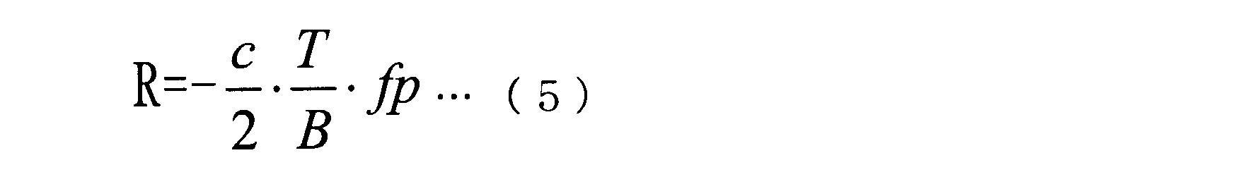
here,
R ;距離
T ;スイープ時間
B ;周波数帯域
fp ;ビート周波数
c ;光速
ビート周波数fpと速度Vとに基づき、連立方程式により、距離Rと速度Vが算出される。

R; distance T; sweep time B; frequency band fp; beat frequency c; speed of light Based on the beat frequency fp and velocity V, the distance R and velocity V are calculated by simultaneous equations.
T ;スイープ時間
B ;周波数帯域
fp ;ビート周波数
c ;光速
ビート周波数fpと速度Vとに基づき、連立方程式により、距離Rと速度Vが算出される。
v :速度
R1、R2 :スイープ1、2の距離
T12 :スイープ1、2の時間間隔
fp :ビート周波数
λ :波長
B :帯域
T :スイープ時間
次いで、角度Θが算出される(ステップS19)。すなわち、測角部36は、DBF部34から送られてくるΔビームに基づき測角を行い、この測角により得られた角度を外部に出力する。 v: speed R1, R2: distance between sweeps 1 and 2 T12: time interval between sweeps 1 and 2 fp: beat frequency λ: wavelength B: band T: sweep time Next, an angle Θ is calculated (step S19). That is, the angle measuring unit 36 performs angle measurement based on the Δ beam sent from the DBF unit 34 and outputs the angle obtained by this angle measurement to the outside.
R1、R2 :スイープ1、2の距離
T12 :スイープ1、2の時間間隔
fp :ビート周波数
λ :波長
B :帯域
T :スイープ時間
次いで、角度Θが算出される(ステップS19)。すなわち、測角部36は、DBF部34から送られてくるΔビームに基づき測角を行い、この測角により得られた角度を外部に出力する。 v: speed R1, R2: distance between
次いで、目標情報が保存される(ステップS20)。すなわち、上記ステップS17で算出された目標の速度V、距離Rおよび角度Θが保存される。次いで、目標が終了したかどうかが調べられる(ステップS21)。すなわち、全ての目標に対する処理が終了したかどうかが調べられる。ステップS21において、目標が終了していない場合には、目標番号が次の番号に変更され、ステップS16に戻って上述した処理が繰り返し実行される。一方、ステップS21において、目標が終了した場合には、計測処理は終了する。
Next, the target information is stored (step S20). That is, the target speed V, distance R, and angle Θ calculated in step S17 are stored. Next, it is checked whether or not the goal is finished (step S21). That is, it is checked whether or not the processing for all the targets has been completed. In step S21, when the target has not ended, the target number is changed to the next number, and the process returns to step S16 and the above-described processing is repeatedly executed. On the other hand, if the target is finished in step S21, the measurement process is finished.
以上説明したように、本発明の実施例1に係るレーダ装置によれば、アップチャープまたはダウンチャープの系列の信号を送受信するために、ビート周波数が同一であり、複数目標の場合のペアリングをする必要がない。また、短いサイクルタイムによるレーダ観測を実現できる。
As described above, according to the radar apparatus according to the first embodiment of the present invention, in order to transmit / receive an up-chirp or down-chirp sequence signal, pairing in the case of multiple beat targets having the same beat frequency is performed. There is no need to do. Also, radar observation with a short cycle time can be realized.
なお、上述した実施例1に係るレーダ装置は、高速フーリエ変換(FFT)した後に、デジタルビーム形成(DBF)を行いビート周波数を求めたが、図12に示すように、デジタルビーム形成(DBF)を行った後に、高速フーリエ変換(FFT)してビート周波数を求めることもできる。
The radar apparatus according to the first embodiment described above performs digital beam forming (DBF) after performing fast Fourier transform (FFT) to obtain the beat frequency. However, as shown in FIG. 12, digital beam forming (DBF) is performed. Then, the beat frequency can be obtained by fast Fourier transform (FFT).
本発明の実施例2に係るレーダ装置は、上述した実施例1に係るMRAV方式に位相モノパルスを組み合わせた方式を採用している。実施例2に係るレーダ装置の構成は、図7に示した実施例1に係るレーダ装置の構成と同じである。
The radar apparatus according to the second embodiment of the present invention employs a method in which a phase monopulse is combined with the MRAV method according to the first embodiment described above. The configuration of the radar apparatus according to the second embodiment is the same as the configuration of the radar apparatus according to the first embodiment illustrated in FIG.
図13は、本発明の実施例2に係るレーダ装置の動作を、測距・速測および測角を行う計測処理を中心に示すフローチャートである。なお、図8のフローチャートに示された実施例1に係る計測処理と同じまたは相当する処理を行うステップには、図8で使用された符号と同一の符号が付されている。以下においては、実施例1と異なる部分が主に説明される。
FIG. 13 is a flowchart showing the operation of the radar apparatus according to the second embodiment of the present invention, centering on measurement processing for performing distance measurement / speed measurement and angle measurement. In addition, the same code | symbol as the code | symbol used in FIG. 8 is attached | subjected to the step which performs the process which is the same as the measurement process which concerns on Example 1 shown by the flowchart of FIG. 8, or an equivalent process. In the following, portions different from the first embodiment will be mainly described.
特に、PRFが同じでサンプルポイント数が少ない場合には、周波数バンクの間隔が大きくなって周波数精度が劣化する。このため、この対策として、実施例2に係るレーダ装置は、図14~図16に示すように、角度軸で用いる位相モノパルスを周波数軸に用いてバンク内の周波数を高精度に観測する。なお、位相モノパルス(位相比較モノパルスと呼ばれる場合もある)は、『吉田孝監修、‘改訂レーダ技術’、電子情報通信学会、pp.274-275(1996)』に説明されている。
Especially, when the PRF is the same and the number of sample points is small, the frequency bank interval becomes large and the frequency accuracy deteriorates. Therefore, as a countermeasure, the radar apparatus according to the second embodiment observes the frequency in the bank with high accuracy using the phase monopulse used on the angle axis as the frequency axis as shown in FIGS. The phase monopulse (sometimes referred to as phase comparison monopulse) is described in “Supervised by Takashi Yoshida,“ Revised Radar Technology ”, IEICE, pp.274-275 (1996)”.
モノパルス測距・測速では、図16に示すように、抽出された目標の周波数のΣ(f)とΔ(f)を用いて、次式の誤差電圧εpが算出される。位相モノパルス処理は、FFT部32で行われる。

In monopulse distance measurement / speed measurement, as shown in FIG. 16, an error voltage εp of the following equation is calculated using Σ (f) and Δ (f) of the extracted target frequency. The phase monopulse processing is performed by the FFT unit 32.
ここで、
Σ ;加算(受信データ1~Nに重みづけ1を乗算した後、FFT)
Δ ;減算(受信データの1~N/2に-1を、N/2+1~Nに重みづけ1を乗算した後、FFT)
* ;複素共役
Re ;実数部
次いで、あらかじめ保存されているΣとΔの周波数特性を用いて算出された誤差電圧εpの基準値ε0がテーブル化(ε0と周波数fの対応)される。その基準テーブルを用いて、上記の観測値εから、ビート周波数fpが抽出される(ステップS16)。そして、抽出されたビート周波数fpを用いて、速度および距離が算出される(ステップS17、S18)。 here,
Σ: Addition (Receiveddata 1 to N multiplied by weighting 1 and then FFT)
Δ: Subtraction (1 to N / 2 of received data is multiplied by -1 and N / 2 + 1 to N is multiplied byweighting 1 and then FFT)
*; Complex conjugate Re; Real part Next, the reference value ε0 of the error voltage εp calculated using the frequency characteristics of Σ and Δ stored in advance is tabulated (corresponding to ε0 and frequency f). Using the reference table, the beat frequency fp is extracted from the observed value ε (step S16). Then, the speed and distance are calculated using the extracted beat frequency fp (steps S17 and S18).
Σ ;加算(受信データ1~Nに重みづけ1を乗算した後、FFT)
Δ ;減算(受信データの1~N/2に-1を、N/2+1~Nに重みづけ1を乗算した後、FFT)
* ;複素共役
Re ;実数部
次いで、あらかじめ保存されているΣとΔの周波数特性を用いて算出された誤差電圧εpの基準値ε0がテーブル化(ε0と周波数fの対応)される。その基準テーブルを用いて、上記の観測値εから、ビート周波数fpが抽出される(ステップS16)。そして、抽出されたビート周波数fpを用いて、速度および距離が算出される(ステップS17、S18)。 here,
Σ: Addition (Received
Δ: Subtraction (1 to N / 2 of received data is multiplied by -1 and N / 2 + 1 to N is multiplied by
*; Complex conjugate Re; Real part Next, the reference value ε0 of the error voltage εp calculated using the frequency characteristics of Σ and Δ stored in advance is tabulated (corresponding to ε0 and frequency f). Using the reference table, the beat frequency fp is extracted from the observed value ε (step S16). Then, the speed and distance are calculated using the extracted beat frequency fp (steps S17 and S18).
なお、重みづけについては、-1または1以外に、サイドローブを低減するために、テーラー分布によるテーラーウェイト等のウェイトが乗算されてもよい。なお、テーラー分布は、例えば、『吉田孝監修、‘改訂レーダ技術’、電子情報通信学会、pp.274-275(1996)』に説明されている。
Regarding weighting, in addition to -1 or 1, weights such as tailor weights based on tailor distribution may be multiplied in order to reduce side lobes. The Taylor distribution is described in, for example, “Supervised by Takashi Yoshida,“ Revised Radar Technology ”, IEICE, pp.274-275 (1996)”.
以上説明したように、本発明の実施例2に係るレーダ装置によれば、各スイープ信号のビート周波数を位相モノパルス誤差電圧に基づき高精度に算出するため、低速目標から高速目標まで速度と距離を高精度に算出できる。
As described above, according to the radar apparatus according to the second embodiment of the present invention, the beat frequency of each sweep signal is calculated with high accuracy based on the phase monopulse error voltage. It can be calculated with high accuracy.
本発明の実施例3に係るレーダ装置は、実施例2に係るレーダ装置の位相モノパルスの代わりに、振幅比較モノパルスを用いる。実施例3に係るレーダ装置の構成は、図7に示した実施例1に係るレーダ装置の構成と同じである。以下、実施例1と相違する部分が主に説明される。なお、振幅比較モノパルス(振幅モノパルスともいう)は、『吉田孝監修、‘改訂レーダ技術’、電子情報通信学会、pp.274-275(1996)』に説明されている。
The radar apparatus according to the third embodiment of the present invention uses an amplitude comparison monopulse instead of the phase monopulse of the radar apparatus according to the second embodiment. The configuration of the radar apparatus according to the third embodiment is the same as the configuration of the radar apparatus according to the first embodiment illustrated in FIG. Hereinafter, portions different from the first embodiment will be mainly described. The amplitude comparison monopulse (also called amplitude monopulse) is described in “Supervised by Takashi Yoshida,“ Revised Radar Technology ”, IEICE, pp.274-275 (1996)”.
抽出した目標の周波数の前後のバンクのΣ(f)とΣ(f-1)およびΣ(f+1)を用いて、絶対値abs(Σ(f-1))と絶対値abs(Σ(f+1))とが比較されて、大きい方が絶対値abs(Σu)として設定される。
Using the Σ (f), Σ (f−1) and Σ (f + 1) of the banks before and after the extracted target frequency, the absolute value abs (Σ (f−1)) and the absolute value abs (Σ (f + 1) ) And the larger one is set as the absolute value abs (Σu).
そして、次式の誤差電圧εaが算出される(図17および18参照)。振幅モノパルス処理は、FFT部32で行われる。

Then, an error voltage εa of the following equation is calculated (see FIGS. 17 and 18). The amplitude monopulse process is performed by the FFT unit 32.
ここで、
Σ ;加算(受信データ1~Nに重みづけ1を乗算後FFT)
Σu ;(f-1)とΣ(f+1)の絶対値の大きい方
そして、予め保存されている絶対値abs(Σ)と絶対値abs(Σu)の周波数特性を用いて算出された誤差電圧εpの基準値ε0がテーブル化(ε0と周波数fの対応)されている。その基準テーブルを用いて、上記の観測値εに基づき、ビート周波数値fpが抽出される。抽出されたビート周波数fpを用いて、速度と距離が算出される。 here,
Σ: Addition (FFT after multiplying receiveddata 1 to N by weighting 1)
Σu; the larger absolute value of (f−1) and Σ (f + 1), and the error voltage εp calculated using the frequency characteristics of the absolute values abs (Σ) and absolute values abs (Σu) stored in advance The reference value ε0 is tabulated (correspondence between ε0 and frequency f). The beat frequency value fp is extracted based on the observed value ε using the reference table. The speed and distance are calculated using the extracted beat frequency fp.
Σ ;加算(受信データ1~Nに重みづけ1を乗算後FFT)
Σu ;(f-1)とΣ(f+1)の絶対値の大きい方
そして、予め保存されている絶対値abs(Σ)と絶対値abs(Σu)の周波数特性を用いて算出された誤差電圧εpの基準値ε0がテーブル化(ε0と周波数fの対応)されている。その基準テーブルを用いて、上記の観測値εに基づき、ビート周波数値fpが抽出される。抽出されたビート周波数fpを用いて、速度と距離が算出される。 here,
Σ: Addition (FFT after multiplying received
Σu; the larger absolute value of (f−1) and Σ (f + 1), and the error voltage εp calculated using the frequency characteristics of the absolute values abs (Σ) and absolute values abs (Σu) stored in advance The reference value ε0 is tabulated (correspondence between ε0 and frequency f). The beat frequency value fp is extracted based on the observed value ε using the reference table. The speed and distance are calculated using the extracted beat frequency fp.
以上説明したように、本発明の実施例3に係るレーダ装置によれば、各スイープ信号のビート周波数を振幅モノパルス誤差電圧に基づき、高精度に算出するため、低速目標から高速目標まで速度と距離を高精度に算出できる。
As described above, according to the radar apparatus according to the third embodiment of the present invention, the beat frequency of each sweep signal is calculated with high accuracy based on the amplitude monopulse error voltage. Can be calculated with high accuracy.
なお、重みづけについては、上述した実施例2に係るレーダ装置と同様に、-1または1以外に、サイドローブを低減するためにテーラーウェイト等のウェイトが乗算されてもよい。
As for the weighting, a weight such as a tailor weight may be multiplied to reduce the side lobes in addition to −1 or 1 as in the radar apparatus according to the second embodiment described above.
本発明の実施例4に係るレーダ装置は、MUSIC方式を採用している。なお、MUSIC方式は、『HARRY B.LEE, "Resolution Threshold of Beams pace MUSIC For Two Closely Spaced Emitters", IEEE Trans. ASSP, Vol.38, No.9, Sept. (1990) 』に説明されている。
The radar apparatus according to Embodiment 4 of the present invention employs the MUSIC method. The MUSIC method is described in “HARRY B.LEE,“ Resolution ”Threshold of Beams“ pace ”MUSIC“ For ”Two“ Closely ”Spaced“ Emitters ”,“ IEEE ”Trans.“ ASSP, ”Vol. 38,“ No. 9, “Sept.” (1990) .
実施例4に係るレーダ装置の構成は、図1に示した実施例1に係るレーダ装置の構成と同じである。図19は、本発明の実施例4に係るレーダ装置の動作を、測距・速測および測角を行う計測処理を中心に示すフローチャートである。なお、図19に示すフローチャートにおいて、図8のフローチャートに示した実施例1に係る計測処理と同じまたは相当する処理を行うステップには、図7で使用した符号と同一の符号が付されている。以下では、実施例1と異なる部分が主に説明される。
The configuration of the radar apparatus according to the fourth embodiment is the same as that of the radar apparatus according to the first embodiment shown in FIG. FIG. 19 is a flowchart illustrating the operation of the radar apparatus according to the fourth embodiment of the present invention, centering on measurement processing for performing distance measurement / speed measurement and angle measurement. In the flowchart shown in FIG. 19, the same reference numerals as those used in FIG. 7 are given to steps for performing the same or corresponding processing as the measurement processing according to the first embodiment shown in the flowchart of FIG. 8. . In the following, portions different from the first embodiment will be mainly described.
実施例4に係るレーダ装置では、図20に示すように、FFT部32がスイープ信号を高速フーリエ変換する際に、Σ信号の極大値のバンクを中心に±Mのバンク信号を抽出して、ビームスペース型MUSICを適用して、高精度にビート周波数を算出する。このレーダ装置は、2回のビート周波数差(距離差)と時間差に基づき速度を算出し、さらにビート周波数と速度とに基づき、絶対距離を算出することにより、Nt個の目標の距離と速度を算出する。
In the radar apparatus according to the fourth embodiment, as illustrated in FIG. 20, when the FFT unit 32 performs a fast Fourier transform on the sweep signal, a bank signal of ± M is extracted around the maximum value bank of the Σ signal, The beat frequency is calculated with high accuracy by applying the beam space type MUSIC. This radar apparatus calculates the speed based on the beat frequency difference (distance difference) twice and the time difference, and further calculates the absolute distance based on the beat frequency and the speed, thereby calculating the distance and speed of Nt targets. calculate.
なお、上述したMUSIC方式を説明した文献は、ビームを角度軸で記述しているが、ビームを高速フーリエ変換(FFT)のような周波数軸に拡長できる。
In addition, although the document explaining the above-mentioned MUSIC system describes the beam on the angle axis, the beam can be expanded on the frequency axis such as fast Fourier transform (FFT).
手順は次の通りである。すなわち、図20(a)に示すように、高速フーリエ変換(FFT)の結果に基づき、振幅が所定のスレショルドを超える目標バンクが抽出される。そして、抽出された目標バンクを中心に、±Mバンク(2M+1個)の複素信号Xmにより、相関行列Rbbが算出される。

The procedure is as follows. That is, as shown in FIG. 20A, a target bank whose amplitude exceeds a predetermined threshold is extracted based on the result of the fast Fourier transform (FFT). Then, a correlation matrix Rbb is calculated from ± M banks (2M + 1) of complex signals Xm around the extracted target bank.
ここで、
Rbb :相関行列
X :X-M~X0~XM(2M+1個)を要素に持つ列ベクトル
H :複素共役転置
次いで、相関行列のRbbの固有ベクトルEbが算出される。そして、固有ベクトルEbの中から、ノイズに対する固有ベクトルENが抽出される。固有ベクトルENと周波数を探索するためのステアリングベクトルwを用いて、次式により、MUSICスペクトルが算出される。図20(b)に示すように、スペクトルが極値を持つビート周波数fpが読み取られる。

here,
Rbb: Correlation matrix X: Column vector having elements XM to X0 to XM (2M + 1) H: Complex conjugate transposition Next, the eigenvector Eb of Rbb of the correlation matrix is calculated. Then, an eigenvector EN for noise is extracted from the eigenvector Eb. Using the eigenvector EN and the steering vector w for searching for the frequency, the MUSIC spectrum is calculated by the following equation. As shown in FIG. 20 (b), the beat frequency fp having an extreme value in the spectrum is read.
Rbb :相関行列
X :X-M~X0~XM(2M+1個)を要素に持つ列ベクトル
H :複素共役転置
次いで、相関行列のRbbの固有ベクトルEbが算出される。そして、固有ベクトルEbの中から、ノイズに対する固有ベクトルENが抽出される。固有ベクトルENと周波数を探索するためのステアリングベクトルwを用いて、次式により、MUSICスペクトルが算出される。図20(b)に示すように、スペクトルが極値を持つビート周波数fpが読み取られる。
Rbb: Correlation matrix X: Column vector having elements XM to X0 to XM (2M + 1) H: Complex conjugate transposition Next, the eigenvector Eb of Rbb of the correlation matrix is calculated. Then, an eigenvector EN for noise is extracted from the eigenvector Eb. Using the eigenvector EN and the steering vector w for searching for the frequency, the MUSIC spectrum is calculated by the following equation. As shown in FIG. 20 (b), the beat frequency fp having an extreme value in the spectrum is read.
ここで、
ws ;時間軸上の要素ws(n)をもつステアリング列ベクトル
fs :探索周波数
PRF :繰り返し周波数
n :1~N(Nはサンプル数)
FFT[]:フーリエ変換
EN :相関行列Rbbの固有ベクトル
H :共役転置
次いで、算出されたビート周波数fpを用いて、速度および距離が算出される(ステップS17、S18)。 here,
ws: steering column vector having element ws (n) on the time axis fs: search frequency PRF: repetition frequency n: 1 to N (N is the number of samples)
FFT []: Fourier transform EN: Eigenvector of correlation matrix Rbb H: Conjugate transposition Next, the calculated beat frequency fp is used to calculate velocity and distance (steps S17 and S18).
以上説明したように、本発明の実施例4に係るレーダ装置によれば、各スイープ信号のビート周波数をFFTおよびMUSIC処理に基づき、高精度に算出するため、低速目標から高速目標まで速度と距離を高精度に算出できる。
As described above, according to the radar apparatus according to Embodiment 4 of the present invention, the beat frequency of each sweep signal is calculated with high accuracy based on the FFT and MUSIC processing. Can be calculated with high accuracy.
図21は、本発明の実施例5に係るレーダ装置の構成を示すブロック図である。このレーダ装置は、図7に示したレーダ装置の信号処理器30aの中のDBF部34とMRAV処理部35との間に、第2FFT部40が追加されて構成されている。第2FFT部40は、DBF部34から出力される信号を高速フーリエ変換する。
FIG. 21 is a block diagram showing a configuration of a radar apparatus according to Embodiment 5 of the present invention. This radar apparatus is configured by adding a second FFT section 40 between the DBF section 34 and the MRAV processing section 35 in the signal processor 30a of the radar apparatus shown in FIG. The second FFT unit 40 performs a fast Fourier transform on the signal output from the DBF unit 34.
実施例5に係るレーダ装置では、図23~図25に示すように、周波数帯域の制約の中で、よりSN比を高め、周波数分解能を向上させるために、複数スイープ間で積分する方法が採用されている。
In the radar apparatus according to the fifth embodiment, as shown in FIGS. 23 to 25, a method of integrating between a plurality of sweeps is adopted in order to further improve the SN ratio and improve the frequency resolution within the restriction of the frequency band. Has been.
このレーダ装置は、FMCW変調されたスイープ信号をN回(#1~#N)送信し、各々のスイープの高速フーリエ変換の結果からNt点の極大値を抽出する。レーダ装置は、図26に示すように、#1~#N1(Mスイープ)と#N2~#N(Mスイープ)のスイープのFFT信号の中で極大値のバンクを抽出した2回のMスイープ毎の高速フーリエ変換の結果のうち極大値となるバンクの信号のビート周波数を算出する。レーダ装置は、2回のビート周波数差(距離差)と時間差とに基づき、速度を算出し、ビート周波数と速度に基づき、絶対距離を算出することにより、Nt個の目標の距離と速度を算出する。
This radar device transmits an FMCW-modulated sweep signal N times (# 1 to #N), and extracts the local maximum value of the Nt point from the result of the fast Fourier transform of each sweep. As shown in FIG. 26, the radar apparatus performs two M sweeps by extracting a bank of local maximum values from FFT signals of # 1 to # N1 (M sweep) and # N2 to #N (M sweep) sweeps. The beat frequency of the bank signal having the maximum value among the results of each fast Fourier transform is calculated. The radar apparatus calculates the speed based on the two beat frequency differences (distance difference) and the time difference, and calculates the absolute distance based on the beat frequency and the speed, thereby calculating the distance and speed of the Nt targets. To do.
図27は、2回のMスイープのうち、各FFTの様子を示している。第1のNサンプルのFFTが実施された後、第2のMサンプルのFFTが実施される。この際、第1FFT部32において、Nサンプルの和Σの他に、Δ(1~N/2とN/2+1~Nの差)が算出される。第2FFT部40において、第1FFTの結果のΣとΔのMサンプルの和の演算により、2段のFFTによるΣとΔ信号が得られる。その後、位相モノパルス演算が実施されて、精度の高い周波数fpが算出されてもよい。
FIG. 27 shows the state of each FFT in the two M sweeps. After the first N-sample FFT is performed, a second M-sample FFT is performed. At this time, the first FFT unit 32 calculates Δ (difference between 1 to N / 2 and N / 2 + 1 to N) in addition to the sum Σ of N samples. In the second FFT unit 40, a Σ and Δ signal by two-stage FFT is obtained by calculating the sum of Σ and Δ of M samples as a result of the first FFT. Thereafter, a phase monopulse calculation may be performed to calculate a highly accurate frequency fp.
図22は、本発明の実施例5に係るレーダ装置の動作を、測距・速測および測角を行う計測処理を中心に示すフローチャートである。なお、図22のフローチャートにおいて、図8のフローチャートに示した実施例1に係る計測処理と同じまたは相当する処理を行うステップには、図8で使用した符号と同一の符号が付されている。以下では、実施例1と異なる部分が中心に説明される。
FIG. 22 is a flowchart showing the operation of the radar apparatus according to the fifth embodiment of the present invention, centering on measurement processing for performing distance measurement / speed measurement and angle measurement. In the flowchart of FIG. 22, the same reference numerals as those used in FIG. 8 are given to steps for performing the same or corresponding processes as the measurement process according to the first embodiment shown in the flowchart of FIG. 8. In the following, a description will be given centering on differences from the first embodiment.
まず、Nスイープが送受信されてスイープ毎にFFT部32により第1FFTが実行される(ステップS11~S13)。次いで、所定のスレショルドを超える目標バンクが抽出される(ステップS51)。次いで、各スイープの目標バンクが第2FFT部39により第2FFTされる(ステップS52)。その後、ピークのビート周波数fpが読み取られる。そして、算出されたビート周波数fpを用いて、速度の算出(ステップS17)と距離の算出(ステップS18)が行われる。
First, N sweeps are transmitted and received, and the first FFT is executed by the FFT unit 32 for each sweep (steps S11 to S13). Next, a target bank exceeding a predetermined threshold is extracted (step S51). Next, the target bank of each sweep is subjected to a second FFT by the second FFT unit 39 (step S52). Thereafter, the peak beat frequency fp is read. Then, speed calculation (step S17) and distance calculation (step S18) are performed using the calculated beat frequency fp.
位相モノパルスの場合には、次の通り処理が行われる。まず、Nスイープが送受信されてスイープ毎にFFT部32により第1FFTが実行される(ステップS11~S13)。次いで、Σ信号とΔ信号が算出され、Σ信号の絶対値が所定のスレショルドを超える目標バンクが抽出される(ステップS51)。次いで、各スイープの目標バンクのΣ信号とΔ信号が第2FFT部40により第2FFTされる(ステップS52)。そして、Σ信号とΔ信号を用いて、周波数fpが算出され、算出された周波数fpを用いて距離と速度が算出される。
In the case of a phase monopulse, the following processing is performed. First, N sweeps are transmitted and received, and the first FFT is executed by the FFT unit 32 for each sweep (steps S11 to S13). Next, the Σ signal and the Δ signal are calculated, and a target bank in which the absolute value of the Σ signal exceeds a predetermined threshold is extracted (step S51). Next, the Σ signal and Δ signal of the target bank of each sweep are subjected to a second FFT by the second FFT unit 40 (step S52). Then, the frequency fp is calculated using the Σ signal and the Δ signal, and the distance and the speed are calculated using the calculated frequency fp.
以上説明したように、本発明の実施例5に係るレーダ装置によれば、各スイープ信号の抽出バンク信号を、更にスイープ間で第2FFTすることにより、第1FFTのみによるバンクよりも、更に高分解能に目標の位置および速度を抽出することができる。
As described above, according to the radar apparatus of the fifth embodiment of the present invention, the extracted bank signal of each sweep signal is further subjected to the second FFT between sweeps, so that the resolution is higher than that of the bank using only the first FFT. The target position and speed can be extracted.
本発明の実施例6に係るレーダ装置は、実施例5に係るレーダ装置において、2回のMスイープ信号から各々の極大値を算出する際に、図28に示すように、Mスイープの信号において、ΣとΔを算出して、モノパルス誤差電圧に基づき高精度にビート周波数を算出する。
In the radar apparatus according to Embodiment 6 of the present invention, when each local maximum value is calculated from two M sweep signals in the radar apparatus according to Embodiment 5, as shown in FIG. , Σ and Δ are calculated, and the beat frequency is calculated with high accuracy based on the monopulse error voltage.
図29は、本発明の実施例6に係るレーダ装置の動作を、測距・速測および測角を行う計測処理を中心に示すフローチャートである。なお、図26のフローチャートにおいて、図22のフローチャートに示した実施例5に係る計測処理と同じまたは相当する処理を行うステップには、図22で使用した符号と同一の符号が付されている。以下では、実施例5と異なる部分が中心に説明される。
FIG. 29 is a flowchart showing the operation of the radar apparatus according to Embodiment 6 of the present invention, centering on measurement processing for measuring distance / speed measurement and angle measurement. In the flowchart of FIG. 26, the same reference numerals as those used in FIG. 22 are assigned to steps that perform the same or corresponding processes as the measurement process according to the fifth embodiment shown in the flowchart of FIG. In the following, a description will be given centering on differences from the fifth embodiment.
まず、Nスイープが送受信されてスイープ毎にFFTが実行される(ステップS11~S13)。次いで、振幅が所定のスレショルドを超える目標バンクが抽出される(ステップS51)。次いで、ステップS51で抽出された目標バンクE1~EMを用いて、第2FFT部40によりΣおよびΔが算出される。そして、抽出された目標の周波数のΣ(f)とΔ(f)を用いて、次式の誤差電圧εpが算出される。

First, N sweeps are transmitted and received, and FFT is executed for each sweep (steps S11 to S13). Next, a target bank whose amplitude exceeds a predetermined threshold is extracted (step S51). Next, Σ and Δ are calculated by the second FFT unit 40 using the target banks E1 to EM extracted in step S51. Then, an error voltage εp of the following equation is calculated using Σ (f) and Δ (f) of the extracted target frequency.
Σ ;加算(E1~EMに重みづけ1を乗算後FFT)
Δ ;減算(E1~EM/2に-1を、EM/2+1~EMに重みづけ1を乗算後、FFT)
* ; 複素共役
Re ; 実数部
次いで、予め保存されているΣとΔの周波数特性を用いて算出された誤差電圧εpの基準値ε0がテーブル化(ε0と周波数fの対応)されている。その基準テーブルを用いて、上記の観測値εに基づき、周波数値fpが抽出される(ステップS16)。そして、抽出されたビート周波数fpを用いて、速度の算出(ステップS17)と距離の算出(ステップS18)が行われる。 Σ: Addition (FFT after multiplying E1 to EM by weight 1)
Δ: Subtraction (E1 to EM / 2 multiplied by −1, EM / 2 + 1 to EM weighted by 1 and then FFT)
*; Complex conjugate Re; Real part Next, the reference value ε0 of the error voltage εp calculated using the frequency characteristics of Σ and Δ stored in advance is tabulated (corresponding to ε0 and the frequency f). Using the reference table, the frequency value fp is extracted based on the observed value ε (step S16). Then, speed calculation (step S17) and distance calculation (step S18) are performed using the extracted beat frequency fp.
以上説明したように、本発明の実施例6に係るレーダ装置によれば、第2FFT部40により第2のFFTを行う際に、位相モノパルスにより周波数を算出することにより、高精度にビート周波数を抽出でき、目標の位置および速度を高精度に抽出できる。
As described above, according to the radar apparatus according to Embodiment 6 of the present invention, when performing the second FFT by the second FFT unit 40, the beat frequency is calculated with high accuracy by calculating the frequency using the phase monopulse. The target position and speed can be extracted with high accuracy.
なお、重みづけについては、上述した実施例2に係るレーダ装置と同様に、-1または1以外に、サイドローブを低減するために、テーラーウェイト等のウェイトが乗算されてもよい。
As for the weighting, a weight such as a tailor weight may be multiplied to reduce the side lobes in addition to −1 or 1 as in the radar apparatus according to the second embodiment described above.
本発明の実施例7に係るレーダ装置は、実施例6に係るレーダ装置おいて、Mスイープ信号から各々の極大値を算出する際に、図28に示すように、MスイープのΣとΣuを算出して、モノパルス誤差電圧から高精度にビート周波数を算出する。
In the radar apparatus according to Embodiment 7 of the present invention, when each local maximum value is calculated from the M sweep signal in the radar apparatus according to Embodiment 6, Σ and Σu of the M sweep are calculated as shown in FIG. The beat frequency is calculated with high accuracy from the monopulse error voltage.
まず、Nスイープが送受信されてスイープ毎に第1FFTが実行される(ステップS11~S13)。次いで、振幅が所定のスレショルドを超える目標バンクが抽出される(ステップS51)。次いで、抽出された目標の周波数の前後のバンクのΣ(f)とΣ(f-1)およびΣ(f+1)を用いて、絶対値abs(Σ(f-1))と絶対値abs(Σ(f+1))が比較されて、大きい方が絶対値abs(Σu)として設定される。
First, N sweeps are transmitted and received, and the first FFT is executed for each sweep (steps S11 to S13). Next, a target bank whose amplitude exceeds a predetermined threshold is extracted (step S51). Next, using the Σ (f), Σ (f−1) and Σ (f + 1) of the banks before and after the extracted target frequency, the absolute value abs (Σ (f−1)) and the absolute value abs (Σ (F + 1)) are compared, and the larger one is set as the absolute value abs (Σu).
そして、次式の誤差電圧εaが算出される。このモノパルス誤差電圧処理は、第2FFT部40により行われる(ステップS61)。

Then, an error voltage εa of the following equation is calculated. The monopulse error voltage process is performed by the second FFT unit 40 (step S61).
ここで、
Σ ;加算(受信データ1~Nに重みづけ1を乗算後FFT)
Σu ;Σ(f-1)とΣ(f+1)の絶対値の大きい方
そして、予め保存されているabs(Σ)とabs(Σu)の周波数特性を用いて算出された誤差電圧εpの基準値ε0がテーブル化(ε0と周波数fの対応)されている。その基準テーブルを用いて、上記の観測値εに基づき、ビート周波数値fpが抽出される。算出されたビート周波数fpを用いて、距離と速度が算出される。 here,
Σ: Addition (FFT after multiplying receiveddata 1 to N by weighting 1)
Σu; the larger absolute value of Σ (f−1) and Σ (f + 1), and the reference value of the error voltage εp calculated using the frequency characteristics of abs (Σ) and abs (Σu) stored in advance ε0 is tabulated (corresponding to ε0 and frequency f). The beat frequency value fp is extracted based on the observed value ε using the reference table. The distance and speed are calculated using the calculated beat frequency fp.
Σ ;加算(受信データ1~Nに重みづけ1を乗算後FFT)
Σu ;Σ(f-1)とΣ(f+1)の絶対値の大きい方
そして、予め保存されているabs(Σ)とabs(Σu)の周波数特性を用いて算出された誤差電圧εpの基準値ε0がテーブル化(ε0と周波数fの対応)されている。その基準テーブルを用いて、上記の観測値εに基づき、ビート周波数値fpが抽出される。算出されたビート周波数fpを用いて、距離と速度が算出される。 here,
Σ: Addition (FFT after multiplying received
Σu; the larger absolute value of Σ (f−1) and Σ (f + 1), and the reference value of the error voltage εp calculated using the frequency characteristics of abs (Σ) and abs (Σu) stored in advance ε0 is tabulated (corresponding to ε0 and frequency f). The beat frequency value fp is extracted based on the observed value ε using the reference table. The distance and speed are calculated using the calculated beat frequency fp.
以上説明したように、本発明の実施例7に係るレーダ装置によれば、第2FFT部40により第2のFFTを行う際に、振幅モノパルスにより周波数を算出することにより、高精度にビート周波数を抽出でき、目標の位置および速度を高精度に抽出できる。
As described above, according to the radar apparatus according to the seventh embodiment of the present invention, when performing the second FFT by the second FFT unit 40, the beat frequency is calculated with high accuracy by calculating the frequency using the amplitude monopulse. The target position and speed can be extracted with high accuracy.
なお、重みづけについては、上述した実施例2に係るレーダ装置と同様に、-1または1以外に、サイドローブを低減するために、テーラーウェイト等のウェイトがを乗算されてもよい。
As for the weighting, a weight such as a tailor weight may be multiplied by a weight other than −1 or 1 in order to reduce the side lobe, similarly to the radar apparatus according to the second embodiment described above.
本発明の実施例8に係るレーダ装置は、図30に示すように、2回のMスイープ信号から各々の極大値を算出する際に、MスイープのFFTおよびMUSIC処理により、ビート周波数を算出する。
As shown in FIG. 30, the radar apparatus according to Example 8 of the present invention calculates the beat frequency by FFT and MUSIC processing of M sweep when calculating each local maximum value from two M sweep signals. .
図31は、本発明の実施例8に係るレーダ装置の動作を、測距・速測および測角を行う計測処理を中心に示すフローチャートである。なお、図31のフローチャートにおいて、図22のフローチャートに示した実施例5に係る計測処理と同じまたは相当する処理を行うステップには、図22で使用した符号と同一の符号が付されている。以下では、実施例5と異なる部分が中心に説明される。
FIG. 31 is a flowchart showing the operation of the radar apparatus according to the eighth embodiment of the present invention, centering on measurement processing for measuring distance / speed measurement and angle measurement. In the flowchart of FIG. 31, the same reference numerals as those used in FIG. 22 are given to steps for performing the same or corresponding processes as the measurement process according to the fifth embodiment shown in the flowchart of FIG. 22. In the following, a description will be given centering on differences from the fifth embodiment.
まず、ステップS11~S13におけるFFTの結果に基づき、振幅が所定のスレショルドを超える目標バンクが抽出される(ステップS51)。次いで、目標バンクのMスイープ分の複素信号Xmに基づき、相関行列Rbbが算出される。

First, a target bank whose amplitude exceeds a predetermined threshold is extracted based on the result of FFT in steps S11 to S13 (step S51). Next, a correlation matrix Rbb is calculated based on the complex signal Xm for M sweeps of the target bank.
ここで、
Rbb :相関行列
X :X1~XM(M個)を要素に持つ列ベクトル
H :複素共役転置
次いで、相関行列Rbbの固有ベクトルEbが算出される。そして、固有ベクトルEbの中のノイズに対する固有ベクトルENが抽出され、この固有ベクトルENと周波数を探索するためのステアリングベクトルwを用いて、次式により、MUSICスペクトルが算出され、スペクトルが極値を持つビート周波数fpが読み取られる。このMUSIC処理は、第2FFT部39により行われる(ステップS71)。

here,
Rbb: Correlation matrix X: Column vector having elements X1 to XM (M) H: Complex conjugate transposition Next, an eigenvector Eb of the correlation matrix Rbb is calculated. Then, an eigenvector EN for noise in the eigenvector Eb is extracted, a MUSIC spectrum is calculated by the following equation using the eigenvector EN and a steering vector w for searching for a frequency, and the beat frequency at which the spectrum has an extreme value is calculated. fp is read. This MUSIC process is performed by the second FFT unit 39 (step S71).
Rbb :相関行列
X :X1~XM(M個)を要素に持つ列ベクトル
H :複素共役転置
次いで、相関行列Rbbの固有ベクトルEbが算出される。そして、固有ベクトルEbの中のノイズに対する固有ベクトルENが抽出され、この固有ベクトルENと周波数を探索するためのステアリングベクトルwを用いて、次式により、MUSICスペクトルが算出され、スペクトルが極値を持つビート周波数fpが読み取られる。このMUSIC処理は、第2FFT部39により行われる(ステップS71)。
Rbb: Correlation matrix X: Column vector having elements X1 to XM (M) H: Complex conjugate transposition Next, an eigenvector Eb of the correlation matrix Rbb is calculated. Then, an eigenvector EN for noise in the eigenvector Eb is extracted, a MUSIC spectrum is calculated by the following equation using the eigenvector EN and a steering vector w for searching for a frequency, and the beat frequency at which the spectrum has an extreme value is calculated. fp is read. This MUSIC process is performed by the second FFT unit 39 (step S71).
ここで、
ws ;時間軸上の要素ws(n)をもつステアリング列ベクトル
fs :探索周波数
Fs :1/スイープ時間間隔
n :1~N(Nはサンプル数)
FFT[]:フーリエ変換
EN :相関行列Rbbの固有ベクトル
H :共役転置
次いで、算出されたビート周波数fpを用いて、速度の算出(ステップS17)と距離の算出(ステップS18)が行われる。 here,
ws; steering column vector having element ws (n) on the time axis fs: search frequency Fs: 1 / sweep time interval n: 1 to N (N is the number of samples)
FFT []: Fourier transform EN: Eigenvector of correlation matrix Rbb H: Conjugate transposition Next, speed calculation (step S17) and distance calculation (step S18) are performed using the calculated beat frequency fp.
以上説明したように、本発明の実施例8に係るレーダ装置によれば、第2FFT部40により第2のFFTを行う際に、FFTおよびMUSIC処理により周波数を算出することにより、高精度にビート周波数を抽出でき、目標の位置、速度を高精度に抽出できる。
As described above, according to the radar apparatus according to the eighth embodiment of the present invention, when the second FFT is performed by the second FFT unit 40, the frequency is calculated by the FFT and MUSIC processing, so that the beat can be accurately performed. The frequency can be extracted, and the target position and speed can be extracted with high accuracy.
本発明の実施例9に係るレーダ装置は、スイープ信号が実数信号である(複素信号でない)場合に、サンプルした信号を複素フーリエ変換して、ビート周波数のうち正(または負)の信号を抽出して、複素信号を得る方式である。この場合には、実際に目標が距離および速度によっては、負(または正)のビート周波数であっても正(または負)と観測されるために、距離、速度を誤る場合がある。この場合には、次の原理により、ビート周波数が負(正)であることを判定することができる。
When the sweep signal is a real signal (not a complex signal), the radar apparatus according to Embodiment 9 of the present invention extracts a positive (or negative) signal from the beat frequency by performing a complex Fourier transform on the sampled signal. Thus, a complex signal is obtained. In this case, depending on the distance and speed, the target is actually observed as positive (or negative) even if the beat frequency is negative (or positive), and therefore the distance and speed may be wrong. In this case, it can be determined that the beat frequency is negative (positive) based on the following principle.
MRAV方式により、遠ざかる速度はv’=-v(R2<R1)<0で観測される(図33参照)。ビート周波数が実際には負の場合、観測される周波数は、
fp’=-2v/λ+2R・B/cT>0
である。したがって、
fp’+2v’/λ=2R・B/cT
(6)式の第3式より、R’=正・(fp’+2v’/λ)=正×2R・B/cT<0
したがって、上式の距離R’は負となり、R’が負の場合には、速度が遠ざかる速度として判定できる。速度が負と判定できれば、v’、fp’およびR’の符号を反転し、v、Rの正常な値を算出する。 According to the MRAV method, the moving speed is observed at v ′ = − v (R2 <R1) <0 (see FIG. 33). If the beat frequency is actually negative, the observed frequency is
fp ′ = − 2v / λ + 2R · B / cT> 0
It is. Therefore,
fp ′ + 2v ′ / λ = 2R · B / cT
From the third equation (6), R ′ = positive · (fp ′ + 2v ′ / λ) = positive × 2R · B / cT <0
Therefore, the distance R ′ in the above expression is negative, and when R ′ is negative, it can be determined that the speed is increasing. If it can be determined that the speed is negative, the signs of v ′, fp ′ and R ′ are reversed, and normal values of v and R are calculated.
図32は、本発明の実施例9に係るレーダ装置の動作を、測距・速測および測角を行う計測処理を中心に示すフローチャートである。なお、図32のフローチャートにおいて、図8のフローチャートに示した実施例1に係る計測処理と同じまたは相当する処理を行うステップには、図8で使用した符号と同一の符号が付されている。以下では、実施例5と異なる部分が中心に説明される。
FIG. 32 is a flowchart showing the operation of the radar apparatus according to Embodiment 9 of the present invention, centering on measurement processing for measuring distance / speed measurement and angle measurement. In the flowchart of FIG. 32, the same reference numerals as those used in FIG. 8 are assigned to steps that perform the same or corresponding processes as the measurement process according to the first embodiment shown in the flowchart of FIG. In the following, a description will be given centering on differences from the fifth embodiment.
MRAV方式による負速度観測方式は次の手順で行われる。2回のスイープの距離差が観測された後、位置変化と時間とに基づき、目標の速度Vが算出される(ステップS17)。次いで、ステップS17で算出された目標の速度Vを用いて、ビート周波数により距離Rが算出される(ステップS18)。次いで、角度Θが算出される(ステップS19)。次いで、距離Rが負であるかどうかが調べられる(ステップS61)。ステップS61において、距離Rが負である場合に、符号反転部(図示せず)により距離R、速度Vおよび角度Θの符号が反転される(ステップS62)。一方、ステップS61において、距離Rが負でない場合には、ステップS62の処理はスキップされる。

The negative velocity observation method by the MRAV method is performed by the following procedure. After the distance difference between the two sweeps is observed, the target velocity V is calculated based on the position change and time (step S17). Next, the distance R is calculated from the beat frequency using the target speed V calculated in step S17 (step S18). Next, the angle Θ is calculated (step S19). Next, it is checked whether or not the distance R is negative (step S61). If the distance R is negative in step S61, the sign inversion unit (not shown) inverts the signs of the distance R, the speed V, and the angle Θ (step S62). On the other hand, if the distance R is not negative in step S61, the process of step S62 is skipped.
以上説明したように、本発明の実施例9に係るレーダ装置によれば、実数のサンプリング周波数を複素フーリエ変換して正(または負)のビート周波数のみを観測する場合に、真の目標信号が負(または正)のビート周波数を持つ場合であっても、算出された距離の符号により、正しい符号を判定して、距離、速度、角度の正しい符号に変換できる。
As described above, according to the radar apparatus according to the ninth embodiment of the present invention, when a real sampling frequency is subjected to complex Fourier transform and only a positive (or negative) beat frequency is observed, a true target signal is obtained. Even when the beat frequency has a negative (or positive) beat frequency, the correct sign can be determined based on the calculated sign of the distance and converted to the correct sign of the distance, speed, and angle.
本発明の実施例10に係るレーダ装置は、観測目標が近距離から遠距離までの広範囲に存在し、速度範囲も広い場合に実施例1または実施例2で採用した方式を適用した。
The radar apparatus according to Example 10 of the present invention employs the method adopted in Example 1 or Example 2 when the observation target exists in a wide range from a short distance to a long distance and the speed range is wide.
図34は、本発明の実施例10に係るレーダ装置の構成を示す系統図である。このレーダ装置は、実施例1に係るレーダ装置にスイープ制御部41が追加されて構成されている。スイープ制御部41は、送受信制御部39およびMRAV処理部35aに、近距離ではスイープ信号の勾配を大きくし、遠距離ではスイープ信号の勾配を小さくした信号を送信するための制御信号を送って、これらを制御する。
FIG. 34 is a system diagram showing a configuration of a radar apparatus according to Embodiment 10 of the present invention. This radar apparatus is configured by adding a sweep control unit 41 to the radar apparatus according to the first embodiment. The sweep control unit 41 sends to the transmission / reception control unit 39 and the MRAV processing unit 35a a control signal for transmitting a signal in which the gradient of the sweep signal is increased at a short distance and the gradient of the sweep signal is decreased at a long distance. Control these.
近距離目標の場合には、FFTされた後のビート周波数軸上で送信信号は直流付近になり、送信信号の受信側への回り込みによるノイズの影響を受けやすくなる。一方、遠距離目標の場合には、直流成分から離隔周波数が大きくなり、ノイズの影響を受けにくい。このため、送受信信号は、図35および図36に示すように、近距離用と遠距離用に分けられ、近距離では周波数勾配が大きくされ、遠距離では周波数勾配が小さくされる。
In the case of a short-distance target, the transmission signal is in the vicinity of DC on the beat frequency axis after the FFT, and is susceptible to noise due to the wraparound of the transmission signal to the reception side. On the other hand, in the case of a long-distance target, the separation frequency increases from the DC component and is not easily affected by noise. For this reason, as shown in FIGS. 35 and 36, the transmission / reception signals are divided into short distance and long distance, and the frequency gradient is increased at the short distance and the frequency gradient is decreased at the long distance.
帯域BとPRFが同じである場合に、近距離ではポイント数が少なくなる。しかし、信号の積分効果よりもノイズを低減できる効果が大きく、所要のSN比を確保でき、遠距離ではポイント数が多いため、信号の積分効果が高く所要のSN比を確保できる。
When the band B and the PRF are the same, the number of points decreases at a short distance. However, the effect of reducing noise is greater than the signal integration effect, and the required S / N ratio can be ensured. Since the number of points is large at a long distance, the signal integration effect is high and the required S / N ratio can be ensured.
以上説明したように、本発明の実施例10に係るレーダ装置によれば、近距離から遠距離まで、ビート周波数軸上で直流成分から離隔した雑音成分の少ない周波数で、距離に応じて積分数の多い信号を送受信でき、高いSN比におけるレーダ観測を実現できる。
As described above, according to the radar apparatus of the tenth embodiment of the present invention, the integral number according to the distance at a frequency with a small noise component separated from the DC component on the beat frequency axis from a short distance to a long distance. Signal can be transmitted and received, and radar observation at a high S / N ratio can be realized.
目標速度が早い場合にはスイープ間の時間は短く、目標速度が遅い場合にはスイープ間の時間は長くすることにより速度精度を向上させることができる。このため、目標速度が未知の場合に、速度精度を高めたい危険度の高い目標を弁別して、その目標を重視した最適なスイープを選定する必要がある。図38は、近距離用と遠距離用の場合の複数の送受信スイープ信号の例を示す。
The speed accuracy can be improved by shortening the time between sweeps when the target speed is fast and increasing the time between sweeps when the target speed is slow. For this reason, when the target speed is unknown, it is necessary to discriminate a high-risk target for which speed accuracy is to be improved and to select an optimum sweep that emphasizes the target. FIG. 38 shows an example of a plurality of transmission / reception sweep signals for short distance and long distance.
図37は、本発明の実施例11に係るレーダ装置の構成を示す系統図である。このレーダ装置は、実施例10に係るレーダ装置の測角部36からスイープ制御部38に対して角度信号が送られるように構成されている。
FIG. 37 is a system diagram showing a configuration of a radar apparatus according to Embodiment 11 of the present invention. This radar apparatus is configured such that an angle signal is sent from the angle measuring section 36 of the radar apparatus according to the tenth embodiment to the sweep control section 38.
危険度の指標としては、距離が近くて向ってくる相対速度が大きい目標に対して、高い重みづけをすればよく、次式で表すことができる。
As a risk index, a high weight may be given to a target having a large relative speed that is approaching at a close distance, and can be expressed by the following equation.
Cr=k×V/R…(14)
ここで、
Cr ;危険度
k ;定数
V ;相対速度
R ;相対距離
図39は、この危険度を用いて、最適なスイープ間隔(スイープ番号)を選定する手順を示すフローチャートである。まず、目標毎に、Cr=k(定数)×V/Rが算出される(ステップS71。S72)。次いで、算出されたCrのうち、正の場合には最大値、負の場合には最小値が抽出される(ステップS74、S76)。その後、抽出されたCrに対応する目標の観測精度を最大にするようにスイープが選定される(ステップS75、S76)。 Cr = k × V / R (14)
here,
Cr; Risk level k; Constant V; Relative speed R; Relative distance FIG. 39 is a flowchart showing a procedure for selecting the optimum sweep interval (sweep number) using this risk level. First, Cr = k (constant) × V / R is calculated for each target (steps S71 and S72). Next, among the calculated Cr, the maximum value is extracted if it is positive, and the minimum value is extracted if it is negative (steps S74 and S76). Thereafter, a sweep is selected so as to maximize the target observation accuracy corresponding to the extracted Cr (steps S75 and S76).
観測精度を最大にするためには、目標速度をV、周波数バンク幅をΔfとすると、次式によりスイープTs(またはTsに近いスイープ番号)を選定すればよい。

In order to maximize the observation accuracy, if the target speed is V and the frequency bank width is Δf, the sweep Ts (or the sweep number close to Ts) may be selected by the following equation.
Crの絶対値のみで判定すると、正速度(近づく速度)と負速度(遠ざかる速度)が混在する。負速度の絶対値が大きい場合には、リスクの高い正速度を優先することができないため、上述した手順で処理が行われる。
Judging only by the absolute value of Cr, there is a mixture of positive speed (approaching speed) and negative speed (moving speed). When the absolute value of the negative speed is large, it is not possible to prioritize the positive speed with high risk.
以上説明したように、本発明の実施例11に係るレーダ装置によれば、スイープ間の時間は、目標速度が早い場合には短く、遅い場合には長くする方が速度精度を向上させることができるため、目標速度が未知の場合に、速度精度を高めたい目標を、危険度を用いて判定することにより、目標に応じた最適なスイープを選定することができる。
As described above, according to the radar apparatus according to the eleventh embodiment of the present invention, the time between sweeps is shorter when the target speed is fast, and longer when the target speed is slow. Therefore, when the target speed is unknown, it is possible to select an optimum sweep corresponding to the target by determining the target whose speed accuracy is to be increased using the degree of risk.
目標が複数の場合には、危険度を判定するよりも、異なるスイープをサイクル毎に周期的に変化させることにより、いずれの目標についても速度および距離精度を高めることができる。本発明の実施例12に係るレーダ装置は、異なるスイープをサイクル毎に周期的に変化させたものである。
When there are a plurality of targets, speed and distance accuracy can be improved for any target by periodically changing different sweeps for each cycle rather than determining the degree of danger. The radar apparatus according to Embodiment 12 of the present invention is such that different sweeps are periodically changed for each cycle.
図40は、実施例12に係るレーダ装置の処理を示すフローチャートである。この処理は、スイープ制御部38により行われる。
FIG. 40 is a flowchart illustrating processing of the radar apparatus according to the twelfth embodiment. This process is performed by the sweep control unit 38.
まず、スイープセットが選定される(ステップS81)。次いで、初期スイープが設定される(ステップS82)。次いで、スイープが設定される(ステップS83)。次いで、サイクルが終了したかどうかが調べられる(ステップS84)。ステップS84において、サイクルが終了していない場合、スイープが変更される(ステップS85)。その後、ステップS83に戻って上述した処理が繰り返される。一方、ステップS84において、サイクルが終了した場合には、処理は終了し、次のサイクルの処理に移る。
First, a sweep set is selected (step S81). Next, an initial sweep is set (step S82). Next, a sweep is set (step S83). Next, it is checked whether or not the cycle is completed (step S84). In step S84, if the cycle has not ended, the sweep is changed (step S85). Then, it returns to step S83 and the process mentioned above is repeated. On the other hand, if the cycle ends in step S84, the process ends, and the process proceeds to the next cycle.
また、図41は、周期の一例を示す図である。この例では、Mサイクルを1単位として、スイープ番号が、S3-S2-S3-S2-S3-S2-S3-S4の8サイクルを繰り返して選定される。
FIG. 41 is a diagram showing an example of a cycle. In this example, with M cycles as one unit, the sweep number is selected by repeating eight cycles of S3-S2-S3-S2-S3-S2-S3-S4.
以上説明したように、本発明の実施例12に係るレーダ装置によれば、異なるスイープをサイクル毎に周期的に変化させることにより、いずれの目標についても速度および距離精度を高めることができる。
As described above, according to the radar apparatus of the twelfth embodiment of the present invention, the speed and distance accuracy can be improved for any target by periodically changing different sweeps for each cycle.
上述したMRAV方式は、2回のスイープによる相対距離差(ビート周波数)の精度に依存するために、SN比が小さい場合には速度および距離が劣化する場合がある。これを改善するために、本発明の実施例13に係るレーダ装置は、図42に示すように、M回の複数スイープ信号を用いて、平滑化の効果を得たものである。実施例13に係るレーダ装置の構成は、図34に示した実施例10に係るレーダ装置の構成と同じである。
Since the MRAV method described above depends on the accuracy of the relative distance difference (beat frequency) between two sweeps, the speed and distance may deteriorate when the SN ratio is small. In order to improve this, as shown in FIG. 42, the radar apparatus according to Embodiment 13 of the present invention obtains a smoothing effect by using M multiple sweep signals. The configuration of the radar apparatus according to Embodiment 13 is the same as that of the radar apparatus according to Embodiment 10 shown in FIG.
図43は、実施例13に係るレーダ装置の処理を示すフローチャートである。この処理では、Mスイープ信号から各スイープ信号の極大値を算出する際に、Mスイープの位相モノパルス(振幅モノパルス、MUSIC)によりビート周波数fpが算出され(ステップS91~S94)、(5)式により、相対距離に換算した結果をR(m、n)(スイープ番号m、目標番号n)とする。
FIG. 43 is a flowchart illustrating processing of the radar apparatus according to the thirteenth embodiment. In this processing, when the maximum value of each sweep signal is calculated from the M sweep signal, the beat frequency fp is calculated by the M sweep phase monopulse (amplitude monopulse, MUSIC) (steps S91 to S94), and the equation (5) is used. The result converted into the relative distance is R (m, n) (sweep number m, target number n).
S(m、n)スイープ間で平滑フィルタにより平滑化され(ステップS95)、この結果により、速度が算出された後、相対距離が算出される(ステップS17~S18)。ステップS91~S94、ステップS95、及びステップS17~S18の処理は、MRAV処理部35で行われる。

Smoothing is performed by a smoothing filter between S (m, n) sweeps (step S95), and the speed is calculated based on the result, and then the relative distance is calculated (steps S17 to S18). The processing of steps S91 to S94, step S95, and steps S17 to S18 is performed by the MRAV processing unit 35.
ここで、
Rs ;平滑距離
m ;スイープ番号(m=1~M)
n ;目標番号
α ;定数
fpとVにより、連立方程式により、距離Rと速度Vが算出される。

here,
Rs; smooth distance m; sweep number (m = 1 to M)
n: target number α; distance R and velocity V are calculated by simultaneous equations using constants fp and V.
Rs ;平滑距離
m ;スイープ番号(m=1~M)
n ;目標番号
α ;定数
fpとVにより、連立方程式により、距離Rと速度Vが算出される。
Rs; smooth distance m; sweep number (m = 1 to M)
n: target number α; distance R and velocity V are calculated by simultaneous equations using constants fp and V.
v :速度
T1M :スイープ1、Mの時間間隔
fp :ビート周波数
λ :波長
B :帯域
T :スイープ時間
なお、平滑化フィルタは、平滑化の効果を得ることができればよく、最小2乗フィルタ等、他のフィルタを用いることもできる。また、速度を算出する際に、1回目とM回目のスイープを用いているが、平滑効果を得ることができればよいので、他のスイープ間隔を用いることもできる。 v: speed T1M: time interval ofsweep 1, M fp: beat frequency λ: wavelength B: band T: sweep time Note that the smoothing filter only needs to obtain a smoothing effect, such as a least square filter, Other filters can also be used. Further, when calculating the speed, the first and M-th sweeps are used, but other sweep intervals may be used as long as a smoothing effect can be obtained.
T1M :スイープ1、Mの時間間隔
fp :ビート周波数
λ :波長
B :帯域
T :スイープ時間
なお、平滑化フィルタは、平滑化の効果を得ることができればよく、最小2乗フィルタ等、他のフィルタを用いることもできる。また、速度を算出する際に、1回目とM回目のスイープを用いているが、平滑効果を得ることができればよいので、他のスイープ間隔を用いることもできる。 v: speed T1M: time interval of
以上説明したように、本発明の実施例13に係るレーダ装置によれば、速度を算出するための相対距離差を複数スイープ(複数時間)で観測して、平滑化する。これにより、相対距離差に誤差がある場合であっても誤差の影響を軽減して、測速および測距の精度を向上させることができる。
As described above, according to the radar apparatus of the thirteenth embodiment of the present invention, the relative distance difference for calculating the speed is observed by a plurality of sweeps (a plurality of times) and smoothed. Thereby, even if there is an error in the relative distance difference, the influence of the error can be reduced, and the accuracy of speed measurement and distance measurement can be improved.
上述したMRAV方式は、2回のスイープによる相対距離差(ビート周波数)の精度に依存する。このため、SN比が小さい場合には速度および距離が劣化する場合がある。これを改善するために、本発明の実施例14に係るレーダ装置は、図44に示すように、M回の複数スイープ信号を用いて、ハフ変換を用いて積分効果を得るとともに、平滑化の効果を得たものである。実施例14に係るレーダ装置の構成は、図36に示した実施例10に係るレーダ装置の構成と同じである。
The MRAV method described above depends on the accuracy of the relative distance difference (beat frequency) between two sweeps. For this reason, when the SN ratio is small, the speed and distance may be deteriorated. In order to improve this, as shown in FIG. 44, the radar apparatus according to Embodiment 14 of the present invention obtains an integration effect using Hough transform using M multiple sweep signals, and performs smoothing. It is an effect. The configuration of the radar apparatus according to Embodiment 14 is the same as that of the radar apparatus according to Embodiment 10 shown in FIG.
図45は、実施例14に係るレーダ装置の処理を示すフローチャートである。この処理では、Mスイープ信号から各スイープ信号の極大値を算出する際に、Mスイープの位相モノパルス(振幅モノパルス、MUSIC)によりビート周波数fpが算出され、F(スイープ番号m、目標番号n)とされる(ステップS92~S94)。
FIG. 45 is a flowchart illustrating processing of the radar apparatus according to the fourteenth embodiment. In this process, when the maximum value of each sweep signal is calculated from the M sweep signal, the beat frequency fp is calculated by the M sweep phase monopulse (amplitude monopulse, MUSIC), and F (sweep number m, target number n) and (Steps S92 to S94).
そして、F(m,n)を用いて、ビート周波数-スイープ軸により、ハフ変換が実施され(ステップS101)、所定のスレショルドを超える極大値(ρp、θp)(p=1~P)が抽出される(ステップS102)。そして、極大値毎に、次の関係式により直線が算出され、この直線とビート周波数軸Xとの交点からビート周波数fpが算出される。

Then, using H (m, n), the Hough transform is performed by the beat frequency-sweep axis (step S101), and the maximum values (ρp, θp) (p = 1 to P) exceeding the predetermined threshold are extracted. (Step S102). Then, for each local maximum value, a straight line is calculated by the following relational expression, and the beat frequency fp is calculated from the intersection of this straight line and the beat frequency axis X.
ここで、
X :ビート周波数
Y :スイープ番号
次に、ビート周波数fpが、(5)式を用いて相対距離に換算され、次式により速度Vpが算出される(ステップS17)。 here,
X: Beat frequency Y: Sweep number Next, the beat frequency fp is converted into a relative distance using the equation (5), and the velocity Vp is calculated by the following equation (step S17).
X :ビート周波数
Y :スイープ番号
次に、ビート周波数fpが、(5)式を用いて相対距離に換算され、次式により速度Vpが算出される(ステップS17)。 here,
X: Beat frequency Y: Sweep number Next, the beat frequency fp is converted into a relative distance using the equation (5), and the velocity Vp is calculated by the following equation (step S17).
Vp=(RM-R1)/(TM-T1)
ここで、
R1,RM : 直線のX軸(ビート周波数軸)のスイープ1とスイープMに対応する相対距離
T1、TM:スイープ1とスイープMの開始点の時間
次いで、ビート周波数fpと速度Vpを用いて、次式により距離が算出される(ステップS18)。ステップS92~S94、ステップS101~102、及びステップS17~S18の処理は、MRAV処理部35で行われる。

Vp = (RM-R1) / (TM-T1)
here,
R1, RM: Relative distance corresponding to sweep 1 and sweep M on the straight X axis (beat frequency axis) T1, TM: Time of the start point ofsweep 1 and sweep M Next, using beat frequency fp and velocity Vp, The distance is calculated by the following equation (step S18). The processes of steps S92 to S94, steps S101 to S102, and steps S17 to S18 are performed by the MRAV processing unit 35.
ここで、
R1,RM : 直線のX軸(ビート周波数軸)のスイープ1とスイープMに対応する相対距離
T1、TM:スイープ1とスイープMの開始点の時間
次いで、ビート周波数fpと速度Vpを用いて、次式により距離が算出される(ステップS18)。ステップS92~S94、ステップS101~102、及びステップS17~S18の処理は、MRAV処理部35で行われる。
here,
R1, RM: Relative distance corresponding to sweep 1 and sweep M on the straight X axis (beat frequency axis) T1, TM: Time of the start point of
Vp :速度
fp :ビート周波数
λ :波長
B :帯域
T :スイープ時間
なお、ハフ変換を実施する際に、ビート周波数軸-スイープ軸が用いられたが、(5)式を用いてビート周波数が相対距離に換算された後に、相対距離-スイープ軸でハフ変換を用いてもよい。 Vp: Velocity fp: Beat frequency λ: Wavelength B: Band T: Sweep time Note that the beat frequency axis-sweep axis was used when performing the Hough transform, but the beat frequency is relative using equation (5). After conversion to distance, Hough transform may be used on the relative distance-sweep axis.
ここで、一般的なハフ変換が説明される。ハフ変換は、画像の中から直線を抽出する手法である。X-Y平面上の直線は、極座標で表現されると、図46および図47に示すように、次式となる。

Here, a general Hough transform will be described. The Hough transform is a technique for extracting a straight line from an image. When a straight line on the XY plane is expressed in polar coordinates, as shown in FIGS. 46 and 47, the following equation is obtained.
上式により、直線とρ、θは一意に対応する。次に、図48に示すように、直線上の3点A、BおよびCを考える。各点を通り、角度θを順に変化させた場合の曲線は、ρ-θ軸で表現されると、図49に示すようになる。3本の曲線は、ある点で交わるが、この点(ρ0、θ0)が、X-Y軸における共通の直線を表している。以上の原理に基づき、ハフ変換の手順は次のようにまとめられる。
に よ り According to the above formula, the straight line and ρ, θ correspond uniquely. Next, as shown in FIG. 48, three points A, B, and C on the straight line are considered. A curve when the angle θ is changed in order through each point is represented by the ρ-θ axis as shown in FIG. The three curves intersect at a certain point, and this point (ρ0, θ0) represents a common straight line on the XY axis. Based on the above principle, the Hough transform procedure is summarized as follows.
(1)ρ-θ軸上の数値を格納するマトリクスが確保される。
(1) A matrix for storing numerical values on the ρ-θ axis is secured.
(2)X-Y軸上の観測値を中心に、θをΔθ毎に変化させながら、ρ-θ軸上のρが算出され、対応するマトリクスの行、列に1が加えられる。この処理は全ての観測値に対して繰り返される。
(2) ρ on the ρ-θ axis is calculated while changing θ every Δθ around the observed value on the XY axis, and 1 is added to the row and column of the corresponding matrix. This process is repeated for all observations.
(3)マトリクスの中で、極大点となる(ρq、θq)(q=1~Q)が抽出される。
(3) The maximum point (ρq, θq) (q = 1 to Q) is extracted from the matrix.
以上の手順により、(ρq、θq)により、Q本の直線を抽出できる。
By the above procedure, Q straight lines can be extracted by (ρq, θq).
以上説明したように、本発明の実施例15に係るレーダ装置によれば、速度を算出するための相対距離差を複数スイープ(複数時間)で観測して、相対距離差-スイープ時間の軸上でハフ変換することにより、複数スイープ間の積分効果を得て信号検出性能を向上させる。また、ハフ変換により抽出した直線の傾きを算出することにより、速度を算出した後、距離を算出することにより、相対距離差に誤差がある場合であっても誤差の影響を軽減して、測速、測距の精度を向上させることができる。
As described above, according to the radar apparatus according to Embodiment 15 of the present invention, the relative distance difference for calculating the speed is observed in a plurality of sweeps (a plurality of times), and the relative distance difference-the sweep time is on the axis. By performing the Hough transform, the integration effect between a plurality of sweeps is obtained and the signal detection performance is improved. In addition, by calculating the slope of the straight line extracted by the Hough transform, the speed is calculated, and then the distance is calculated to reduce the influence of the error even if there is an error in the relative distance difference. The accuracy of distance measurement can be improved.
上述したMRAV方式は、2回のスイープによる相対距離差(ビート周波数)の精度に依存するために、SN比が小さい場合には速度および距離が劣化する場合がある。これを改善するために、本発明の実施例15に係るレーダ装置は、図50に示すように、M回の複数スイープ信号を用いて、振幅積分して積分効果を得るとともに、平滑化の効果を得たものである。実施例15に係るレーダ装置の構成は、図34に示した実施例10に係るレーダ装置の構成と同じである。
Since the MRAV method described above depends on the accuracy of the relative distance difference (beat frequency) between two sweeps, the speed and distance may deteriorate when the SN ratio is small. In order to improve this, as shown in FIG. 50, the radar apparatus according to Embodiment 15 of the present invention obtains an integration effect by performing amplitude integration using M multiple sweep signals, and also provides a smoothing effect. Is obtained. The configuration of the radar apparatus according to Embodiment 15 is the same as that of the radar apparatus according to Embodiment 10 shown in FIG.
図51は、実施例15に係るレーダ装置の処理を示すフローチャートである。この処理では、Mスイープ信号から各々のスイープ信号の極大値を算出する際に、Mスイープの位相モノパルス(振幅モノパルス、MUSIC)によりビート周波数fp((5)式により、相対距離Rpに相当)が算出され、F(スイープ番号m、目標番号n)とされる(ステップS92~S94)。
FIG. 51 is a flowchart illustrating processing of the radar apparatus according to the fifteenth embodiment. In this processing, when the maximum value of each sweep signal is calculated from the M sweep signal, the beat frequency fp (corresponding to the relative distance Rp according to the equation (5)) is obtained from the M sweep phase monopulse (amplitude monopulse, MUSIC). Calculated and set to F (sweep number m, target number n) (steps S92 to S94).
そして、F(m,n)を用いて、ビート周波数-スイープ軸より、周波数バンク毎に振幅積分(ビデオ積分)が実施され(ステップS111)、所定のスレショルドを超える周波数バンクfbが抽出される(ステップS112)。
Then, amplitude integration (video integration) is performed for each frequency bank from the beat frequency-sweep axis using F (m, n) (step S111), and a frequency bank fb exceeding a predetermined threshold is extracted (step S111). Step S112).
次いで、周波数バンクfbに対して、スレショルドを超えるスイープのF(m、n)により、次式で表現できるスイープ時刻mと相対距離Rpとの最小2乗直線が算出され(ステップS114)、最小2乗直線の勾配より速度が算出される(ステップS17)。
Next, the least square line between the sweep time m and the relative distance Rp, which can be expressed by the following equation, is calculated for the frequency bank fb by the sweep F (m, n) exceeding the threshold (step S114). The speed is calculated from the gradient of the power line (step S17).
Rp=a・t+b
ここで、
Rp :相対距離
t :スイープの開始時刻
a :直線勾配(速度Vpに対応)
b :定数
次いで、ビート周波数fpと速度Vpを用いて、次式により距離が算出される(ステップS18)。ステップS92~S94、ステップS111~114、及びステップS17~S18の処理は、MRAV処理部35で行われる。

Rp = a · t + b
here,
Rp: relative distance t: sweep start time a: linear gradient (corresponding to velocity Vp)
b: Constant Next, using the beat frequency fp and the velocity Vp, the distance is calculated by the following equation (step S18). The processes of steps S92 to S94, steps S111 to 114, and steps S17 to S18 are performed by theMRAV processing unit 35.
ここで、
Rp :相対距離
t :スイープの開始時刻
a :直線勾配(速度Vpに対応)
b :定数
次いで、ビート周波数fpと速度Vpを用いて、次式により距離が算出される(ステップS18)。ステップS92~S94、ステップS111~114、及びステップS17~S18の処理は、MRAV処理部35で行われる。
here,
Rp: relative distance t: sweep start time a: linear gradient (corresponding to velocity Vp)
b: Constant Next, using the beat frequency fp and the velocity Vp, the distance is calculated by the following equation (step S18). The processes of steps S92 to S94, steps S111 to 114, and steps S17 to S18 are performed by the
Vp :速度
fp :ビート周波数
λ :波長
B :帯域
T :スイープ時間
なお、(19)式で用いるfpとしては、各スイープにおける平均値等を用いてもよい。 Vp: speed fp: beat frequency λ: wavelength B: band T: sweep time In addition, as fp used in the equation (19), an average value or the like in each sweep may be used.
fp :ビート周波数
λ :波長
B :帯域
T :スイープ時間
なお、(19)式で用いるfpとしては、各スイープにおける平均値等を用いてもよい。 Vp: speed fp: beat frequency λ: wavelength B: band T: sweep time In addition, as fp used in the equation (19), an average value or the like in each sweep may be used.
以上説明したように、本発明の実施例15に係るレーダ装置によれば、速度を算出するための相対距離差を複数スイープ(複数時間)で観測して、相対距離差-スイープ時間の軸上でビデオ積分することにより、複数スイープ間の積分効果を得て信号検出性能を向上させることができる。また、最小2乗直線でフィッティングすることにより抽出した直線の傾きを算出することにより、速度を算出した後、距離を算出する。これにより、相対距離差に誤差がある場合であっても誤差の影響を軽減して、測速、測距の精度を向上させることができる。
As described above, according to the radar apparatus according to Embodiment 15 of the present invention, the relative distance difference for calculating the speed is observed in a plurality of sweeps (a plurality of times), and the relative distance difference-the sweep time is on the axis. By integrating the video at, it is possible to improve the signal detection performance by obtaining an integration effect between a plurality of sweeps. In addition, the distance is calculated after calculating the speed by calculating the slope of the extracted straight line by fitting with the least square line. Thereby, even if there is an error in the relative distance difference, the influence of the error can be reduced and the accuracy of speed measurement and distance measurement can be improved.
本発明は、車両までの距離および車両の速度を計測するレーダ装置に利用することができる。
The present invention can be used in a radar device that measures the distance to a vehicle and the speed of the vehicle.
10 アンテナ
11 アンテナ送信素子
12 アンテナ受信素子
20 送受信器
21 送信器
22 ミキサ
30,30a 信号処理器
31 AD変換器
32 FFT部
34 DBF部
35,35a MRAV処理部(測距・測速)
36 測角部
37 アップ系列ダウン系列抽出部
38 スイープ制御部
39 送受信制御部
40 第2FFT部 DESCRIPTION OFSYMBOLS 10 Antenna 11 Antenna transmitting element 12 Antenna receiving element 20 Transmitter / receiver 21 Transmitter 22 Mixer 30, 30a Signal processor 31 AD converter 32 FFT section 34 DBF section 35, 35a MRAV processing section (ranging / speed measurement)
36Angle measurement unit 37 Up sequence down sequence extraction unit 38 Sweep control unit 39 Transmission / reception control unit 40 Second FFT unit
11 アンテナ送信素子
12 アンテナ受信素子
20 送受信器
21 送信器
22 ミキサ
30,30a 信号処理器
31 AD変換器
32 FFT部
34 DBF部
35,35a MRAV処理部(測距・測速)
36 測角部
37 アップ系列ダウン系列抽出部
38 スイープ制御部
39 送受信制御部
40 第2FFT部 DESCRIPTION OF
36
Claims (14)
- FMCW変調されたスイープ信号をM回送信する送受信器と、
前記送受信器からの送信に応答して受信されたM回のスイープ信号を高速フーリエ変換するFFT部と、
前記FFT部でフーリエ変換することにより得られたM回のスイープ信号から各スイープ信号の極大値を算出する際に、Mスイープの位相モノパルス、振幅モノパルスまたはMUSICによりビート周波数が算出された結果F(スイープ番号、目標番号)を用いて、ビート周波数-スイープ軸において、ビート周波数毎にスイープ方向に振幅積分し、所定のスレショルドを超えた周波数バンク毎に、前記所定のスレショルドを超えたスイープ番号の相対距離とスイープ時刻との最小2乗直線を算出し、前記最小2乗直線の勾配により目標の速度を算出し、前記目標の距離を算出するMRAV処理部と、
を備えるレーダ装置。 A transceiver for transmitting the FMCW modulated sweep signal M times;
An FFT unit for fast Fourier transforming M sweep signals received in response to transmission from the transceiver;
When the maximum value of each sweep signal is calculated from M sweep signals obtained by performing Fourier transform in the FFT unit, the result F (the beat frequency is calculated by M sweep phase monopulse, amplitude monopulse or MUSIC) Sweep number, target number) is used to integrate the amplitude in the sweep direction for each beat frequency on the beat frequency-sweep axis, and for each frequency bank that exceeds the predetermined threshold, the relative number of the sweep number that exceeds the predetermined threshold An MRAV processing unit that calculates a least-squares line between a distance and a sweep time, calculates a target speed based on a gradient of the least-squares line, and calculates the target distance;
A radar apparatus comprising: - 前記MRAV処理部は、スイープ信号が高速フーリエ変換される際に、Σ信号とΔ信号の2系列の高速フーリエ変換の結果を用いて、Σ信号の極大値のバンクに対してモノパルス誤差信号を算出し、または、Σ信号の極大値のバンクに対して、隣接するバンクのうちの大きい方の信号をΣuとし、ΣとΣuとに基づきモノパルス誤差信号を算出し、または、Σ信号の極大値のバンクを中心に±Mのバンク信号を抽出して、FFTおよびMUSIC方式を適用して、モノパルス誤差信号を算出し、算出されたモノパルス誤差信号に基づきバンク内で高精度にビート周波数を算出する請求項1記載のレーダ装置。 When the sweep signal is subjected to fast Fourier transform, the MRAV processing unit calculates a monopulse error signal for the bank of the maximum value of the Σ signal using the result of the two series of fast Fourier transform of the Σ signal and the Δ signal. Or, with respect to the bank of the maximum value of the Σ signal, the larger signal of the adjacent banks is set as Σu, and a monopulse error signal is calculated based on Σ and Σu, or the maximum value of the Σ signal is A ± M bank signal is extracted centering on the bank, the monopulse error signal is calculated by applying the FFT and the MUSIC method, and the beat frequency is calculated with high accuracy in the bank based on the calculated monopulse error signal. Item 2. The radar device according to item 1.
- FMCW変調されたスイープ信号を少なくとも2回送信する送受信器と、
前記送受信器からの送信に応答して受信された少なくとも2回のスイープ信号を高速フーリエ変換するFFT部と、
前記FFT部でフーリエ変換することにより得られた少なくとも2回のスイープ信号に基づき、前記送受信器による少なくとも2回のスイープの各々に対応するビート周波数を算出し、算出されたビート周波数差と時間差とに基づき速度を算出し、算出された速度とビート周波数とに基づき距離を算出することにより、複数の目標の距離と速度を算出するMRAV処理部と、
を備えるレーダ装置。 A transceiver for transmitting an FMCW modulated sweep signal at least twice;
An FFT unit for fast Fourier transforming at least two sweep signals received in response to transmission from the transceiver;
Based on at least two sweep signals obtained by Fourier transform in the FFT unit, a beat frequency corresponding to each of at least two sweeps by the transceiver is calculated, and the calculated beat frequency difference and time difference are calculated. A MRAV processing unit that calculates a distance based on the calculated speed and a beat frequency, and calculates a distance and a speed of a plurality of targets,
A radar apparatus comprising: - 前記MRAV処理部は、スイープ信号が高速フーリエ変換される際に、Σ信号とΔ信号の2系列の高速フーリエ変換の結果を用いて、Σ信号の極大値のバンクに対してモノパルス誤差信号を算出し、または、Σ信号の極大値のバンクに対して、隣接するバンクのうちの大きい方の信号をΣuとし、ΣとΣuとに基づきモノパルス誤差信号を算出し、または、Σ信号の極大値のバンクを中心に±Mのバンク信号を抽出して、FFTおよびMUSIC方式を適用して、モノパルス誤差信号を算出し、算出されたモノパルス誤差信号に基づきバンク内で高精度にビート周波数を算出する請求項3記載のレーダ装置。 When the sweep signal is subjected to fast Fourier transform, the MRAV processing unit calculates a monopulse error signal for the bank of the maximum value of the Σ signal using the result of the two series of fast Fourier transform of the Σ signal and the Δ signal. Or, with respect to the bank of the maximum value of the Σ signal, the larger signal of the adjacent banks is set as Σu, and a monopulse error signal is calculated based on Σ and Σu, or the maximum value of the Σ signal is A ± M bank signal is extracted centering on the bank, the monopulse error signal is calculated by applying the FFT and the MUSIC method, and the beat frequency is calculated with high accuracy in the bank based on the calculated monopulse error signal. Item 4. The radar device according to item 3.
- 前記FFT部の出力を高速フーリエ変換する第2FFT部を備え、
前記送受信器は、FMCW変調されたスイープ信号をN回(#1~#N)送信し、
前記MRAV処理部は、各スイープの高速フーリエ変換の結果に基づき極大値を抽出し、#1~#N1(Mスイープ)と#N2~#N(Mスイープ)のスイープのFFT信号の中で極大値のバンクを抽出した2回のMスイープ毎の前記第2FFT部による高速フーリエ変換の結果のうち極大値となるバンクの信号のビート周波数を算出する請求項3記載のレーダ装置。 A second FFT unit for performing a fast Fourier transform on the output of the FFT unit;
The transceiver transmits an FMCW modulated sweep signal N times (# 1 to #N),
The MRAV processing unit extracts a local maximum value based on the result of the fast Fourier transform of each sweep, and maximizes the FFT signal of sweeps of # 1 to # N1 (M sweep) and # N2 to #N (M sweep). 4. The radar apparatus according to claim 3, wherein a beat frequency of a bank signal having a maximum value among the results of fast Fourier transform performed by the second FFT unit for every two M sweeps from which a bank of values has been extracted is calculated. - 前記MRAV処理部は、2回のMスイープ信号から各々の極大値を算出する際に、MスイープのΣとΔを算出して、モノパルス誤差電圧から高精度にビート周波数を算出する請求項3記載のレーダ装置。 4. The MRAV processing unit calculates Σ and Δ of M sweep when calculating each local maximum value from two M sweep signals, and calculates beat frequency with high accuracy from monopulse error voltage. Radar equipment.
- 前記MRAV処理部は、2回のMスイープ信号から各々の極大値を算出する際に、MスイープのΣとΣuを算出して、モノパルス誤差電圧から高精度にビート周波数を算出する請求項3記載のレーダ装置。 4. The MRAV processing unit calculates Σ and Σu of M sweep when calculating each local maximum value from two M sweep signals, and calculates a beat frequency with high accuracy from a monopulse error voltage. Radar equipment.
- 前記MRAV処理部は、2回のMスイープ信号から各々の極大値を算出する際に、MスイープのFFTおよびMUSIC処理により、ビート周波数を算出する請求項3のレーダ装置。 The radar apparatus according to claim 3, wherein the MRAV processing unit calculates a beat frequency by FFT and MUSIC processing of M sweep when calculating each local maximum value from two M sweep signals.
- スイープ信号が実数の場合に、サンプルした信号を複素フーリエ変換して、ビート周波数のうち正または負の信号を抽出して複素信号を得る方式の場合に、算出した距離の符号により、距離、速度および角度の符号を反転させる符号反転部を備える請求項3記載のレーダ装置。 When the sweep signal is a real number, a complex Fourier transform is performed on the sampled signal, and a positive or negative signal is extracted from the beat frequency to obtain a complex signal. The radar apparatus according to claim 3, further comprising: a sign inversion unit that inverts the sign of the angle.
- 近距離ではスイープ信号の勾配を大きくし、遠距離ではスイープ信号の勾配を小さくした信号を送信するように制御するスイープ制御部を備える請求項3記載のレーダ装置。 The radar apparatus according to claim 3, further comprising a sweep control unit that performs control so as to transmit a signal having a large sweep signal gradient at a short distance and a small sweep signal gradient at a long distance.
- 前記スイープ制御部は、速度と距離に基づき算出された危険度を用いて、時間間隔の異なる2つのスイープを選定する請求項10記載のレーダ装置。 11. The radar apparatus according to claim 10, wherein the sweep control unit selects two sweeps having different time intervals using a risk calculated based on a speed and a distance.
- 前記スイープ制御部は、時間間隔の異なる2つのスイープをサイクル毎に周期的に変化させて選定する請求項10記載のレーダ装置。 11. The radar apparatus according to claim 10, wherein the sweep control unit selects two sweeps having different time intervals by periodically changing each sweep.
- FMCW変調されたスイープ信号をM回送信する送受信器と、
前記送受信器からの送信に応答して受信されたM回のスイープ信号を高速フーリエ変換するFFT部と、
前記FFT部でフーリエ変換することにより得られたM回のスイープ信号から各スイープ信号の極大値を算出する際に、Mスイープの位相モノパルス、振幅モノパルスまたはMUSICによりビート周波数が算出された結果F(スイープ番号、目標番号)を用いて、スイープ間で平滑化し、平滑された結果に基づき速度を算出した後、距離を算出するMRAV処理部と、
を備えるレーダ装置。 A transceiver for transmitting the FMCW modulated sweep signal M times;
An FFT unit for fast Fourier transforming M sweep signals received in response to transmission from the transceiver;
When the maximum value of each sweep signal is calculated from M sweep signals obtained by performing Fourier transform in the FFT unit, the result F (the beat frequency is calculated by M sweep phase monopulse, amplitude monopulse or MUSIC) Using a sweep number, a target number), smoothing between sweeps, calculating a speed based on the smoothed result, and then calculating a distance;
A radar apparatus comprising: - FMCW変調されたスイープ信号をM回送信する送受信器と、
前記送受信器からの送信に応答して受信されたM回のスイープ信号を高速フーリエ変換するFFT部と、
前記FFT部でフーリエ変換することにより得られたM回のスイープ信号から各スイープ信号の極大値を算出する際に、Mスイープの位相モノパルス、振幅モノパルスまたはMUSICによりビート周波数が算出された結果F(スイープ番号、目標番号)を用いて、ビート周波数-スイープ軸においてハフ変換により極大値を算出し、算出された極大値に対応する速度をビート周波数差とスイープ時間とから算出した後、距離を算出するMRAV処理部
と、
を備えるレーダ装置。 A transceiver for transmitting the FMCW modulated sweep signal M times;
An FFT unit for fast Fourier transforming M sweep signals received in response to transmission from the transceiver;
When the maximum value of each sweep signal is calculated from M sweep signals obtained by performing Fourier transform in the FFT unit, the result F (the beat frequency is calculated by M sweep phase monopulse, amplitude monopulse or MUSIC) Using the sweep number and target number), calculate the maximum value by Hough transform on the beat frequency-sweep axis, calculate the speed corresponding to the calculated maximum value from the beat frequency difference and the sweep time, and then calculate the distance An MRAV processing unit,
A radar apparatus comprising:
Priority Applications (3)
| Application Number | Priority Date | Filing Date | Title |
|---|---|---|---|
| EP10777616A EP2434309A1 (en) | 2009-05-20 | 2010-03-19 | Radar device |
| CN2010800012066A CN101971050A (en) | 2009-05-20 | 2010-03-19 | Radar device |
| US12/996,058 US20110122013A1 (en) | 2009-05-20 | 2010-03-19 | Radar apparatus |
Applications Claiming Priority (2)
| Application Number | Priority Date | Filing Date | Title |
|---|---|---|---|
| JP2009-121902 | 2009-05-20 | ||
| JP2009121902A JP5468304B2 (en) | 2009-05-20 | 2009-05-20 | Radar equipment |
Publications (1)
| Publication Number | Publication Date |
|---|---|
| WO2010134381A1 true WO2010134381A1 (en) | 2010-11-25 |
Family
ID=43126070
Family Applications (1)
| Application Number | Title | Priority Date | Filing Date |
|---|---|---|---|
| PCT/JP2010/054839 WO2010134381A1 (en) | 2009-05-20 | 2010-03-19 | Radar device |
Country Status (5)
| Country | Link |
|---|---|
| US (1) | US20110122013A1 (en) |
| EP (1) | EP2434309A1 (en) |
| JP (1) | JP5468304B2 (en) |
| CN (1) | CN101971050A (en) |
| WO (1) | WO2010134381A1 (en) |
Cited By (1)
| Publication number | Priority date | Publication date | Assignee | Title |
|---|---|---|---|---|
| WO2017208670A1 (en) * | 2016-05-30 | 2017-12-07 | 日本電気株式会社 | Object sensing device, vehicle-mounted radar system, surveillance radar system, object sensing method, and program |
Families Citing this family (34)
| Publication number | Priority date | Publication date | Assignee | Title |
|---|---|---|---|---|
| JP5656505B2 (en) * | 2010-08-12 | 2015-01-21 | 三菱電機株式会社 | Radar equipment |
| JP5660973B2 (en) * | 2011-05-20 | 2015-01-28 | 三菱電機株式会社 | Radar equipment |
| JP5871559B2 (en) * | 2011-10-20 | 2016-03-01 | 三菱電機株式会社 | Radar equipment |
| CN103827690B (en) * | 2011-12-12 | 2015-11-25 | 三菱电机株式会社 | Radar installations |
| KR101185480B1 (en) | 2012-03-15 | 2012-10-02 | 국방과학연구소 | Improvement method of the accuracy of beat frequency in fmcw radar for detecting and tracking a high speed moving target |
| JP6275370B2 (en) * | 2012-04-11 | 2018-02-07 | 三菱電機株式会社 | Radar equipment |
| ITTO20120417A1 (en) * | 2012-05-09 | 2013-11-10 | St Microelectronics Srl | PROCEDURE AND DEVICES FOR DEVELOPING RADAR SIGNALS, FOR EXAMPLE FOR ROAD SAFETY SYSTEMS, ITS RELATED PRODUCT |
| JP6092596B2 (en) * | 2012-11-28 | 2017-03-08 | 富士通テン株式会社 | Radar apparatus and signal processing method |
| US8884814B2 (en) * | 2012-12-06 | 2014-11-11 | Chung Shan Institute Of Science And Technology, Armaments Bureau, M. N.D. | Processing method for FMCW radar signal with dual pulse repetition frequency |
| CN103630888B (en) * | 2013-02-27 | 2017-03-22 | 中国科学院电子学研究所 | High-precision real-time microwave velocity and distance measuring device based on symmetrical triangle LFMCW (Linear Frequency Modulation Continuous Wave) radar |
| JP2015129695A (en) * | 2014-01-08 | 2015-07-16 | 株式会社東芝 | Pulse compression radar device and radar signal processing method therefor |
| JP6222523B2 (en) * | 2014-03-11 | 2017-11-01 | 日本電気株式会社 | Moving target extraction system, moving target extraction method, information processing apparatus, control method thereof, and control program |
| DE102014107343A1 (en) * | 2014-05-26 | 2015-11-26 | Hella Kgaa Hueck & Co. | Method for operating a radar sensor |
| US9841497B2 (en) * | 2014-06-05 | 2017-12-12 | Infineon Technologies Ag | Method, device and system for processing radar signals |
| DE102014212281A1 (en) * | 2014-06-26 | 2015-12-31 | Robert Bosch Gmbh | Radar measurement with different viewing areas |
| JP6305259B2 (en) * | 2014-07-25 | 2018-04-04 | 株式会社東芝 | Radar system and radar signal processing method thereof |
| JP6382635B2 (en) * | 2014-08-22 | 2018-08-29 | 株式会社東芝 | Radar system and radar signal processing method thereof |
| US9784828B2 (en) * | 2014-08-27 | 2017-10-10 | Texas Insturments Incorporated | FMCW doppler processing algorithm for achieving CW performance |
| JP5925264B2 (en) * | 2014-09-10 | 2016-05-25 | 三菱電機株式会社 | Radar equipment |
| KR102303236B1 (en) * | 2014-11-20 | 2021-09-16 | 현대모비스 주식회사 | FRCW radar system and the operating method |
| JP6352837B2 (en) * | 2015-03-02 | 2018-07-04 | 株式会社東芝 | Radar system and radar signal processing method thereof |
| US10613208B2 (en) | 2015-05-15 | 2020-04-07 | Texas Instruments Incorporated | Low complexity super-resolution technique for object detection in frequency modulation continuous wave radar |
| US10078131B2 (en) * | 2015-09-15 | 2018-09-18 | Texas Instruments Incorporated | Method and apparatus for FMCW radar processing |
| EP3264131A1 (en) * | 2016-07-01 | 2018-01-03 | Autoliv Development AB | A vehicle radar for environmental detection |
| US10641884B2 (en) * | 2017-01-26 | 2020-05-05 | Mitsumi Electric Co., Ltd. | Radar transceiver |
| WO2019008640A1 (en) * | 2017-07-03 | 2019-01-10 | 三菱電機株式会社 | Signal processing device, signal processing method, signal processing program, and radar system |
| CN107462884A (en) * | 2017-07-25 | 2017-12-12 | 上海航征测控系统有限公司 | A kind of moving target detecting method and system based on frequency modulated continuous wave radar |
| DE102017119624A1 (en) * | 2017-08-28 | 2019-04-18 | HELLA GmbH & Co. KGaA | Method for operating a radar system of a vehicle |
| US11327176B2 (en) * | 2017-12-27 | 2022-05-10 | Mitsubishi Electric Corporation | Laser radar device |
| JP7056212B2 (en) * | 2018-02-20 | 2022-04-19 | 株式会社デンソー | Direction estimation method and equipment |
| US10962636B2 (en) * | 2018-08-13 | 2021-03-30 | GM Global Technology Operations LLC | Range and direction of arrival migration with doppler ambiguity estimation |
| CN109557536B (en) * | 2018-11-30 | 2020-10-27 | 四川九洲防控科技有限责任公司 | Angle measuring method, angle measuring device and angle measuring system |
| CN111521988B (en) * | 2019-02-01 | 2023-11-14 | 比亚迪股份有限公司 | Radar angle measurement method and device based on beam forming, radar and vehicle |
| CN111232778B (en) * | 2020-03-04 | 2022-06-14 | 日立楼宇技术(广州)有限公司 | Method and device for counting number of people in elevator car |
Citations (5)
| Publication number | Priority date | Publication date | Assignee | Title |
|---|---|---|---|---|
| JPH11281729A (en) * | 1998-03-31 | 1999-10-15 | Toyota Central Res & Dev Lab Inc | Beam switched radar apparatus |
| JP2006242695A (en) * | 2005-03-02 | 2006-09-14 | Denso Corp | Onboard radar device |
| JP2007286033A (en) * | 2006-03-23 | 2007-11-01 | Omron Corp | Radio detector and method |
| JP2009069124A (en) * | 2007-09-18 | 2009-04-02 | Mitsubishi Electric Corp | Radar system |
| JP2009293968A (en) * | 2008-06-03 | 2009-12-17 | Fujitsu Ten Ltd | Signal processing apparatus and radar system |
Family Cites Families (5)
| Publication number | Priority date | Publication date | Assignee | Title |
|---|---|---|---|---|
| CN1023515C (en) * | 1991-06-28 | 1994-01-12 | 中国人民解放军空军第五研究所 | Self-correlation long-distance transmitting-receiving radar positioning method |
| WO1998002760A1 (en) * | 1996-06-28 | 1998-01-22 | Milkovich Systems Engineering | Improved fast fourier transform sensor processor using enhanced frequency domain principles |
| JP2002257928A (en) * | 2001-03-06 | 2002-09-11 | Murata Mfg Co Ltd | Radar |
| WO2006013614A1 (en) * | 2004-08-02 | 2006-02-09 | Mitsubishi Denki Kabushiki Kaisha | Radar |
| CN101042435B (en) * | 2006-03-23 | 2011-03-23 | 欧姆龙汽车电子株式会社 | Single pulse radar device |
-
2009
- 2009-05-20 JP JP2009121902A patent/JP5468304B2/en active Active
-
2010
- 2010-03-19 EP EP10777616A patent/EP2434309A1/en not_active Withdrawn
- 2010-03-19 US US12/996,058 patent/US20110122013A1/en not_active Abandoned
- 2010-03-19 CN CN2010800012066A patent/CN101971050A/en not_active Withdrawn
- 2010-03-19 WO PCT/JP2010/054839 patent/WO2010134381A1/en active Application Filing
Patent Citations (5)
| Publication number | Priority date | Publication date | Assignee | Title |
|---|---|---|---|---|
| JPH11281729A (en) * | 1998-03-31 | 1999-10-15 | Toyota Central Res & Dev Lab Inc | Beam switched radar apparatus |
| JP2006242695A (en) * | 2005-03-02 | 2006-09-14 | Denso Corp | Onboard radar device |
| JP2007286033A (en) * | 2006-03-23 | 2007-11-01 | Omron Corp | Radio detector and method |
| JP2009069124A (en) * | 2007-09-18 | 2009-04-02 | Mitsubishi Electric Corp | Radar system |
| JP2009293968A (en) * | 2008-06-03 | 2009-12-17 | Fujitsu Ten Ltd | Signal processing apparatus and radar system |
Non-Patent Citations (3)
| Title |
|---|
| HARRY B. LEE: "Resolution Threshold of Beamspace MUSIC For Two Closely Spaced Emitters", IEEE TRANS. ASSP, vol. 38, no. 9, September 1990 (1990-09-01) |
| TAKASHI YOSHIDA: "Radar Technology", 1996, INSTITUTE OF ELECTRONICS, INFORMATION AND COMMUNICATION ENGINEERS, article "Radar Technology, revised version", pages: 274,275 |
| TAKASHI YOSHIDA: "Radar Technology, revised version", 1996, INSTITUTE OF ELECTRONICS, INFORMATION AND COMMUNICATION ENGINEERS, pages: 274,275 |
Cited By (3)
| Publication number | Priority date | Publication date | Assignee | Title |
|---|---|---|---|---|
| WO2017208670A1 (en) * | 2016-05-30 | 2017-12-07 | 日本電気株式会社 | Object sensing device, vehicle-mounted radar system, surveillance radar system, object sensing method, and program |
| JPWO2017208670A1 (en) * | 2016-05-30 | 2019-03-28 | 日本電気株式会社 | Object detection apparatus, in-vehicle radar system, surveillance radar system, object detection method and program |
| US11194033B2 (en) | 2016-05-30 | 2021-12-07 | Nec Corporation | Object sensing device, automotive radar system, surveillance radar system, object sensing method, and program |
Also Published As
| Publication number | Publication date |
|---|---|
| EP2434309A1 (en) | 2012-03-28 |
| JP5468304B2 (en) | 2014-04-09 |
| US20110122013A1 (en) | 2011-05-26 |
| CN101971050A (en) | 2011-02-09 |
| JP2010271115A (en) | 2010-12-02 |
Similar Documents
| Publication | Publication Date | Title |
|---|---|---|
| JP5468304B2 (en) | Radar equipment | |
| JP5407272B2 (en) | Radar equipment | |
| JP5247068B2 (en) | Radar equipment | |
| US10914818B2 (en) | Angle-resolving FMCW radar sensor | |
| CN104280728B (en) | Radar sensor and the method for running radar sensor | |
| JP4665962B2 (en) | Target detection device | |
| JP5871559B2 (en) | Radar equipment | |
| US8947293B2 (en) | Radar apparatus | |
| JP5578866B2 (en) | Radar equipment | |
| JP6576595B2 (en) | Radar equipment | |
| CN108885254B (en) | Object detection device | |
| JP3821688B2 (en) | Radar equipment | |
| CN105467381A (en) | Radar device | |
| EP4009074B1 (en) | Co-prime coded (cpc) doppler division multiplexing (ddm) mimo radar method and system | |
| JP2009025159A (en) | Radar device | |
| JP5656505B2 (en) | Radar equipment | |
| JP2010175457A (en) | Radar apparatus | |
| JP5508877B2 (en) | Radar equipment | |
| JP7160561B2 (en) | Azimuth calculation device and azimuth calculation method | |
| JP2010281605A (en) | Radar system | |
| JP2014153088A (en) | Rader system and tracking processor | |
| KR102235571B1 (en) | Range Resolution enhancement method using low cost multi radar | |
| JP5491981B2 (en) | Radar equipment | |
| JP6161311B2 (en) | Radar apparatus and target detection method | |
| WO2022249552A1 (en) | Information processing device and information processing method |
Legal Events
| Date | Code | Title | Description |
|---|---|---|---|
| WWE | Wipo information: entry into national phase |
Ref document number: 201080001206.6 Country of ref document: CN |
|
| WWE | Wipo information: entry into national phase |
Ref document number: 12996058 Country of ref document: US |
|
| WWE | Wipo information: entry into national phase |
Ref document number: 2010777616 Country of ref document: EP |
|
| 121 | Ep: the epo has been informed by wipo that ep was designated in this application |
Ref document number: 10777616 Country of ref document: EP Kind code of ref document: A1 |
|
| NENP | Non-entry into the national phase |
Ref country code: DE |