JP5491981B2 - Radar equipment - Google Patents
Radar equipment Download PDFInfo
- Publication number
- JP5491981B2 JP5491981B2 JP2010138277A JP2010138277A JP5491981B2 JP 5491981 B2 JP5491981 B2 JP 5491981B2 JP 2010138277 A JP2010138277 A JP 2010138277A JP 2010138277 A JP2010138277 A JP 2010138277A JP 5491981 B2 JP5491981 B2 JP 5491981B2
- Authority
- JP
- Japan
- Prior art keywords
- unit
- sweep
- correlation tracking
- axis
- value
- Prior art date
- Legal status (The legal status is an assumption and is not a legal conclusion. Google has not performed a legal analysis and makes no representation as to the accuracy of the status listed.)
- Active
Links
Images


Classifications
-
- G—PHYSICS
- G01—MEASURING; TESTING
- G01S—RADIO DIRECTION-FINDING; RADIO NAVIGATION; DETERMINING DISTANCE OR VELOCITY BY USE OF RADIO WAVES; LOCATING OR PRESENCE-DETECTING BY USE OF THE REFLECTION OR RERADIATION OF RADIO WAVES; ANALOGOUS ARRANGEMENTS USING OTHER WAVES
- G01S13/00—Systems using the reflection or reradiation of radio waves, e.g. radar systems; Analogous systems using reflection or reradiation of waves whose nature or wavelength is irrelevant or unspecified
- G01S13/02—Systems using reflection of radio waves, e.g. primary radar systems; Analogous systems
- G01S13/06—Systems determining position data of a target
- G01S13/42—Simultaneous measurement of distance and other co-ordinates
- G01S13/44—Monopulse radar, i.e. simultaneous lobing
- G01S13/4454—Monopulse radar, i.e. simultaneous lobing phase comparisons monopulse, i.e. comparing the echo signals received by an interferometric antenna arrangement
-
- G—PHYSICS
- G01—MEASURING; TESTING
- G01S—RADIO DIRECTION-FINDING; RADIO NAVIGATION; DETERMINING DISTANCE OR VELOCITY BY USE OF RADIO WAVES; LOCATING OR PRESENCE-DETECTING BY USE OF THE REFLECTION OR RERADIATION OF RADIO WAVES; ANALOGOUS ARRANGEMENTS USING OTHER WAVES
- G01S13/00—Systems using the reflection or reradiation of radio waves, e.g. radar systems; Analogous systems using reflection or reradiation of waves whose nature or wavelength is irrelevant or unspecified
- G01S13/02—Systems using reflection of radio waves, e.g. primary radar systems; Analogous systems
- G01S13/06—Systems determining position data of a target
- G01S13/42—Simultaneous measurement of distance and other co-ordinates
-
- G—PHYSICS
- G01—MEASURING; TESTING
- G01S—RADIO DIRECTION-FINDING; RADIO NAVIGATION; DETERMINING DISTANCE OR VELOCITY BY USE OF RADIO WAVES; LOCATING OR PRESENCE-DETECTING BY USE OF THE REFLECTION OR RERADIATION OF RADIO WAVES; ANALOGOUS ARRANGEMENTS USING OTHER WAVES
- G01S13/00—Systems using the reflection or reradiation of radio waves, e.g. radar systems; Analogous systems using reflection or reradiation of waves whose nature or wavelength is irrelevant or unspecified
- G01S13/02—Systems using reflection of radio waves, e.g. primary radar systems; Analogous systems
- G01S13/50—Systems of measurement based on relative movement of target
- G01S13/58—Velocity or trajectory determination systems; Sense-of-movement determination systems
- G01S13/583—Velocity or trajectory determination systems; Sense-of-movement determination systems using transmission of continuous unmodulated waves, amplitude-, frequency-, or phase-modulated waves and based upon the Doppler effect resulting from movement of targets
- G01S13/584—Velocity or trajectory determination systems; Sense-of-movement determination systems using transmission of continuous unmodulated waves, amplitude-, frequency-, or phase-modulated waves and based upon the Doppler effect resulting from movement of targets adapted for simultaneous range and velocity measurements
Description
本発明の実施形態は、相関追尾により車両の速度を観測するレーダ装置に関する。 Embodiments described herein relate generally to a radar apparatus that observes the speed of a vehicle by correlation tracking.
道路を走行する車両の速度をレーダ装置によって観測する場合は、他車両や背景といった複雑かつ多数の反射点が存在する中で目標車両を検出して相関追尾が行われる。このような環境下において、アンテナビーム幅が広く、FMCW(Frequency Modulated Continuous Wave)方式によるビート周波数軸の分解能が低い場合は、角度軸でも周波数軸でもメインローブの中に複数の反射点が存在することになる。このため、従来のダウンスイープとアップスイープのペアリングにより距離および速度を算出する方法では、ペアリングの誤りに起因するゴーストが生じる。なお、FMCW方式については、例えば『吉田孝監修、電子情報通信学会、“改訂レーダ技術”、pp.274-275(1996)』に説明されている。 When observing the speed of a vehicle traveling on a road with a radar device, correlation tracking is performed by detecting a target vehicle in the presence of complicated and numerous reflection points such as other vehicles and backgrounds. Under such circumstances, when the antenna beam width is wide and the resolution of the beat frequency axis by the FMCW (Frequency Modulated Continuous Wave) method is low, there are a plurality of reflection points in the main lobe in both the angle axis and the frequency axis. It will be. For this reason, in the conventional method of calculating the distance and the speed by the pairing of the down sweep and the up sweep, a ghost due to a pairing error occurs. The FMCW method is described in, for example, “Supervised by Takashi Yoshida, IEICE,“ Revised Radar Technology ”, pp.274-275 (1996)”.
上述したように、従来のレーダ装置では、ダウンスイープとアップスイープとをペアリングすることにより距離および速度を算出するので、ペアリングの誤りに起因するゴーストが生じ、安定した相関追尾ができないという問題がある。 As described above, in the conventional radar device, the distance and speed are calculated by pairing the down sweep and the up sweep, so that a ghost due to a pairing error occurs and stable correlation tracking cannot be performed. There is.
本発明は、ペアリングを不要にして、安定した相関追尾ができるレーダ装置を提供することを課題とする。 An object of the present invention is to provide a radar apparatus that can perform stable correlation tracking without pairing.
上記の課題を解決するために、実施形態に係るレーダ装置は、FMCW方式のダウンスイープまたはアップスイープの信号を繰り返し送受信する送受信器と、送受信器からの信号に基づく測角値を用いてビート周波数の空間を表すfbx−fby軸に座標変換するビート周波数軸変換部と、ビート周波数軸変換部における変換によって得られたfbx−fby軸の空間において位置、速度および加速度を用いて相関追尾を行う相関追尾部と、相関追尾部における相関追尾によって得られた結果をX−Y軸の位置および速度に変換するX−Y軸変換部を備えたことを特徴とする。 In order to solve the above-described problem, a radar apparatus according to an embodiment uses a transmitter / receiver that repeatedly transmits / receives an FMCW down sweep or up sweep signal, and a beat frequency using an angle measurement value based on the signal from the transmitter / receiver. A beat frequency axis conversion unit that converts coordinates to the fbx-fby axis representing the space of the correlation, and a correlation that performs correlation tracking using the position, velocity, and acceleration in the space of the fbx-fby axis obtained by conversion in the beat frequency axis conversion unit A tracking unit and an XY axis conversion unit that converts a result obtained by correlation tracking in the correlation tracking unit into a position and a speed of an XY axis are provided.
以下、実施形態について、図面を参照しながら詳細に説明する。 Hereinafter, embodiments will be described in detail with reference to the drawings.
(第1の実施形態)
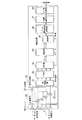
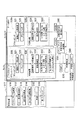
第1の実施形態に係るレーダ装置において採用されている方式をFSAT(Frequency Space data Association and Tracking)と呼ぶ。図1は、第1の実施形態に係るレーダ装置の構成を示す系統図である。このレーダ装置は、アンテナ10、送受信器20および信号処理器30を備えている。
(First embodiment)
A method adopted in the radar apparatus according to the first embodiment is called FSAT (Frequency Space Data Association and Tracking). FIG. 1 is a system diagram showing the configuration of the radar apparatus according to the first embodiment. The radar apparatus includes an
アンテナ10は、アンテナ送信素子11と複数のアンテナ受信素子12とから構成されている。アンテナ送信素子11は、送受信器20から送信信号として送られてくる電気信号を電波に変換して外部に送出する。複数のアンテナ受信素子12は、外部からの電波を受信して電気信号に変換し、受信信号として送受信器20に送る。
The
送受信器20は、送信器21と複数のミキサ22を備えており、複数のミキサ22は、複数のアンテナ受信素子12にそれぞれ対応して設けられている。一般的なアップチャープとダウンチャープの信号を送信信号として用いるFMCW方式の場合は、送信器21でスイープした送信信号を生成し、アンテナ送信素子11および複数のミキサ22に送る。複数のミキサ22は、複数のアンテナ受信素子12からそれぞれ受け取った受信信号を、送信器21からの信号に応じて周波数変換してビート周波数信号を生成し、信号処理器30に送る。
The
信号処理器30は、AD変換器31、FFT部32、DBF部33、検出部34、測角部35、ビート周波数軸変換部36、相関追尾部37およびX−Y軸変換部38を備えている。
The
AD変換器31は、送受信器20からアナログ信号として送られてくるビート周波数信号をデジタル信号に変換し、素子信号としてFFT部32に送る。FFT部32は、AD変換器31から送られてくる素子信号を高速フーリエ変換により周波数軸上の信号に変換し、DBF部33に送る。
The
DBF部33は、FFT部32から送られてくる周波数軸上の信号を用いて、ΣビームとΔビームを形成する。このDBF部33で形成されたΣビームは検出部34に送られ、Δビームは測角部35に送られる。
The
検出部34は、DBF部33から送られてくるΣビームに基づき距離および速度を検出し、それらを表す値をビート周波数軸変換部36に送る。また、検出部34は、DBF部33から送られてきたΣビームを測角部35に送る。
The
測角部35は、検出部34から送られてくるΣビームおよびDBF部33から送られてくるΔビームを用いて、位相モノパルス測角方式により測角を行う。なお、位相モノパルス測角方式については、例えば『電子情報通信学会、“改訂レーダ技術”、pp.262-264(1996)』に説明されている。
The
位相モノパルス測角の場合のビームは次式で表すことができる。

ここで、
bm(θ);Σビーム出力
en(θ);素子パターン(n=1〜N)
Wm(θ) ;複素ウェイト(n=1〜N)
n ;素子番号(n=1〜N)
λ ;波長
また、位相モノパルス測角の場合には、次式のΔビームを用いて測角することができる。
bm (θ); Σ beam output en (θ); element pattern (n = 1 to N)
Wm (θ); complex weight (n = 1 to N)
n: Element number (n = 1 to N)
λ: Wavelength
In the case of phase monopulse angle measurement, angle measurement can be performed using a Δ beam of the following equation.
ここで、
Δm(θ) ; Δビーム出力
en(θ); 素子パターン
Wm(n) ; 複素ウェイト(n=1〜N)
n ; 素子番号(n=1〜N)
λ ; 波長
bmとΔmを用いて、誤差電圧εは、次式で表すことができる。
Δm (θ); Δ beam output en (θ); element pattern Wm (n); complex weight (n = 1 to N)
n: Element number (n = 1 to N)
λ: Using the wavelengths bm and Δm, the error voltage ε can be expressed by the following equation.
ここで、
* ;複素共役
この誤差電圧εと、予め保存されている誤差電圧εと測角値θの対応テーブル(または、多項式近似値)を用いて、測角値を算出できる。以上のようにして測角部35で算出された測角値は、ビート周波数軸変換部36に送られる。
here,
*: Complex conjugate The angle measurement value can be calculated using the error voltage ε and a correspondence table (or polynomial approximation value) of the error voltage ε and the angle measurement value θ stored in advance. The angle measurement value calculated by the
ビート周波数軸変換部36は、検出部34から送られてくる距離および速度を表す値と、測角部35から送られてくる測角値とに基づき、ビート周波数軸変換を行う。ここで、ΣビームとΔビームの信号をビート周波数fbで代表して表記すると、ビート周波数fbは、次のように表すことができる。
ここで、
fb:ビ−ト周波数
B :周波数帯域
T :スイープ時間
R :距離
c :光速
V :速度
λ :波長
kr:2B/(Tc)
kv:λ/2
ビート周波数fbの微分、更にその微分で表現すると、次の通りである。
fb: Beat frequency B: Frequency band T: Sweep time R: Distance c: Light speed V: Speed λ: Wavelength kr: 2B / (Tc)
kv: λ / 2
It is as follows when it expresses with the derivative of beat frequency fb, and also the derivative.
これらを距離R、速度Vおよび加速度Aで表現すると、次の通りである。
ここで、
R:距離
V:速度
A:加速度
これを、測角値θを用いてX−Y軸に変換できる。
R: Distance V: Speed A: Acceleration This can be converted into an XY axis using the measured angle value θ.
ここで、
fb; ビート周波数
θ ; 測角値
このようにしてビート周波数軸変換部36においてfbx−fbyに座標変換された結果(fbxおよびfby)は、相関追尾部37に送られる。
here,
fb; Beat frequency θ; Angle measurement value The result (fbx and fby) of the coordinate conversion into fbx-fby in the beat frequency
相関追尾部37は、ビート周波数軸変換部36から送られてくるfbxおよびfbyの空間で、位置、速度および加速度を用いて相関追尾処理を実行する。
The
上述したfbxおよびfbyは、1回微分と2回微分を用いて、等加速度運動(加速度の時間微分は0)とすると、次式で表現できる。
fbxとfbyの速度(1回微分)と加速度(2回微分)まで観測すれば、(8)式と(9)式に代入して、位置(xs、ys)と速度(vxs、vys)を算出することができる。 If fbx and fby velocity (1st derivative) and acceleration (2nd derivative) are observed, the position (xs, ys) and velocity (vxs, vys) are substituted into equations (8) and (9). Can be calculated.
このfbxとfbyの速度、加速度は、例えばαβγフィルタを用いると、次式で表される(図14参照)。なお、αβγフィルタについては、例えば非特許文献1および非特許文献2に追尾フィルタとして説明されているので、必要に応じて参照されたい。
初期値は次の通りである。
この相関追尾を用いて平滑値を算出し、(8)〜(10)式を用いて、位置(xs、ys)と速度(vxs、vys)を算出することができる。相関追尾部37における相関追尾処理により得られる平滑値および予測値は、X−Y軸変換部38に送られる。
A smooth value is calculated using this correlation tracking, and a position (xs, ys) and a velocity (vxs, vys) can be calculated using equations (8) to (10). The smoothed value and the predicted value obtained by the correlation tracking process in the
X−Y軸変換部38は、相関追尾部37から送られてきた平滑値および予測値をX−Y軸の位置および速度に変換し、外部に送る。
The XY
次に、第1の実施形態に係るレーダ装置の動作を、図2に示すフローチャートを参照しながら説明する。最初に、信号処理が行われる(ステップS10)。具体的には、まず、ダウン送受信が行われる(ステップS11)。すなわち、送受信器20では、送信器21で生成されたダウンスイープの送信信号を、アンテナ10のアンテナ送信素子11および複数のミキサ22に送る。アンテナ送信素子11は、送受信器20から送信信号として送られてくる電気信号を電波に変換して外部に送出する。アンテナ10の複数のアンテナ受信素子12は、外部からの電波を受信して電気信号に変換し、受信信号として送受信器20に送る。送受信器20に含まれる複数のミキサ22は、複数のアンテナ受信素子12からそれぞれ受け取った受信信号を、送信器21からの信号に応じて周波数変換してビート周波数信号を生成し、信号処理器30に送る。
Next, the operation of the radar apparatus according to the first embodiment will be described with reference to the flowchart shown in FIG. First, signal processing is performed (step S10). Specifically, first, down transmission / reception is performed (step S11). That is, the transmitter /
信号処理器30においては、AD変換器31は、送受信器20からアナログ信号として送られてくるビート周波数信号をデジタル信号に変換し、素子信号としてFFT部32に送る。FFT部32は、AD変換器31から送られてくる素子信号を高速フーリエ変換により周波数軸上の信号に変換し、DBF部33に送る。DBF部33は、FFT部32から送られてくる周波数軸上の信号を用いて、ΣビームとΔビームを形成し、それぞれ検出部34および測角部35に送る。検出部34は、DBF部33から送られてくるΣビームに基づき距離および速度を検出し、それらを表す値をビート周波数軸変換部36に送る。また、検出部34は、DBF部33から送られてきたΣビームを測角部35に送る。
In the
次いで、測角値θbが算出される(ステップS13)。すなわち、測角部35は、検出部34から送られてくるΣビームおよびDBF部33から送られてくるΔビームを用いて、位相モノパルス測角方式により測角を行い、測角値θbをビート周波数軸変換部36に送る。
Next, an angle measurement value θb is calculated (step S13). That is, the
次いで、fbx−fbyへの座標変換が行われる(ステップS14)。すなわち、ビート周波数軸変換部36は、検出部34から送られてくる距離および速度を表す値と、測角部35から送られてくる測角値とに基づき、ビート周波数軸変換を行い、fbx−fbyに座標変換された結果(fbxおよびfby)を相関追尾部37に送る。
Next, coordinate conversion to fbx-fby is performed (step S14). In other words, the beat frequency
次いで、グルーピング処理が行われる(ステップS20)。このグルーピング処理はオプションであり、複数ビームを形成する場合に実行される。グルーピング処理の内容は後述する。 Next, a grouping process is performed (step S20). This grouping process is optional and is executed when a plurality of beams are formed. The contents of the grouping process will be described later.
次いで、相関追尾処理が行われる(ステップS30)。この相関追尾処理は、相関処理部37において実行される。相関追尾処理においては、まず、相関処理が行われる(ステップS31)。すなわち、NN値が抽出される。次いで、初航跡が確立される(ステップS32)。次いで、fbx、fby空間におけるαβγ追尾が行われる(ステップS33)。すなわち、fbx、fbyの平滑値が算出される。次いで、fbx、fbyの平滑値より、X、Y、Vx、Vy、AxおよびAyが算出される(ステップS34)。
Next, correlation tracking processing is performed (step S30). This correlation tracking process is executed in the
以上の相関追尾処理が終了すると、次いで、平滑値のフィルタ処理が行われる(ステップS40)。これにより、平滑位置および平滑速度が出力される。その後、信号処理S10のステップS11に戻り、上述した処理が繰り返される。 When the above correlation tracking process is completed, a smoothing filter process is then performed (step S40). Thereby, a smooth position and a smooth speed are output. Then, it returns to step S11 of signal processing S10, and the process mentioned above is repeated.
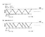
図3は、第1の実施形態で用いられるスイープ波形の例を示す。スイープ波形としては、ダウンスイープまたはアップスイープの一方のみでよいが、一般的にダウンスイープとアップスイープの組み合わせで表現している。相関追尾のためのサイクルタイム(相関追尾の時間間隔)内のスイープを、一般にNスイープとした場合、NスイープのFFT波形の同一ビート周波数において、振幅積分した結果によりスレショルド判定して検出した後、検出バンク(ビート周波数バンク)において、Nスイープ分の測角を行い、測角値を平均することにより、測角値の精度を高めることができる。 FIG. 3 shows an example of a sweep waveform used in the first embodiment. The sweep waveform may be either a down sweep or an up sweep, but is generally expressed by a combination of a down sweep and an up sweep. When the sweep within the cycle time for correlation tracking (correlation tracking time interval) is generally N sweep, at the same beat frequency of the FFT waveform of N sweep, after detecting by threshold determination by the result of amplitude integration, In the detection bank (beat frequency bank), the angle measurement for N sweeps is performed, and the angle measurement values are averaged, thereby improving the accuracy of the angle measurement values.
また、上述したグルーピング処理は、以下のように構成できる。グルーピング処理においては、まず、複数ビーム間合成が行われる(ステップS21)。すなわち、複数ビーム間の観測値(fbx、fby)が合成される。次いで、グルーピングが行われる(ステップS22)。すなわち、複数の観測値の中から、振幅値の大きい順から極値を抽出し、抽出点のビート周波数軸の周りに所定のゲートを形成し、そのゲート内にある観測値(ビート周波数)を各振幅値により重みづけするといった重心演算を用いて、複数点をグルーピングする。このグルーピングした結果は相関追尾部37に送られる。
Further, the above-described grouping process can be configured as follows. In the grouping process, first, combining between a plurality of beams is performed (step S21). That is, the observation values (fbx, fby) between the plurality of beams are combined. Next, grouping is performed (step S22). That is, an extreme value is extracted from the multiple observed values in descending order of amplitude value, a predetermined gate is formed around the beat frequency axis of the extraction point, and the observed value (beat frequency) in the gate is determined. A plurality of points are grouped using a centroid calculation such as weighting by each amplitude value. The grouped result is sent to the
また、(fbx、fby)より、位置および速度の平滑値を算出後、路肩反射点の速度(自車両速度)や路肩位置等によるフィルタを適用して、不要点を抑圧する処理を付加するように構成することもできる。 Further, after calculating a smooth value of the position and speed from (fbx, fby), a filter based on the speed of the road shoulder reflection point (vehicle speed), the road shoulder position, etc. is applied to add processing for suppressing unnecessary points. It can also be configured.
以上説明したように、第1の実施形態に係るレーダ装置によれば、ダウンスイープまたはアップスイープのみの繰り返しスイープを用いて、ビート周波数を観測し、ビート周波数空間で相関追尾し、相関追尾の結果(平滑値および予測値)を用いてX−Y軸に変換するので、ダウンスイープとアップスイープのペアリングが不要であり、誤ペアリングによるゴーストは生じない。その結果、複雑な背景下においても、目標の観測位置精度を高めて、安定した相関追尾を実現できる。 As described above, according to the radar apparatus of the first embodiment, the beat frequency is observed using the repeated sweep of only the down sweep or the up sweep, the correlation tracking is performed in the beat frequency space, and the correlation tracking result is obtained. Since (smooth value and predicted value) are used for conversion to the XY axes, pairing of down sweep and up sweep is unnecessary, and ghost due to erroneous pairing does not occur. As a result, even under complicated background, it is possible to improve the target observation position accuracy and realize stable correlation tracking.
(第2の実施形態)
第2の実施形態に係るレーダ装置において採用される方式をIFSAT(;Improved FSAT)と呼ぶ。上述した第1の実施形態に係るレーダ装置では、ダウンスイープまたはアップスイープの一方のみを用いている。この場合、fbx−fby空間とX−Y空間の関係により、非線形の誤差が生じる。まず、この誤差について説明する。
(Second Embodiment)
A method adopted in the radar apparatus according to the second embodiment is called IFSAT (; Improved FSAT). In the radar apparatus according to the first embodiment described above, only one of the down sweep and the up sweep is used. In this case, a non-linear error occurs due to the relationship between the fbx-fby space and the XY space. First, this error will be described.
X−Y空間とfbx−fby空間の測角値θが等しいものとし、等加速度運動を前提とすると、図4および図5を参照して、ビート周波数fb、その1回微分および2回微分は次式で表現できる。
(15)式をx、y成分に分離すると次式で表すことができる。ただし、等加速度運動(加速度の時間微分は0)とする。
ここで、
xs、ys :位置の平滑値
vxs、vys:速度の平滑値
axs,ays:加速度の平滑値
θ :測角値
(8)式と(16)式、(9)式と(17)式を比較する。左辺のfbx、fbyを両者で等しいとすると、
(8)式→(16)式
xs→xs・sinθ
vxs→vxs・sinθ
axs→axs・sinθ
(9)式→(17)式
ys→ys・cosθ
vys→vys・cosθ
ays→ays・cosθ
が対応しており、θによる誤差分があることがわかる。これは、fbとθより、fbxとfbyを(7)式の関係で定義したものと、(16)および(17)式で定義したfbxとfbyが異なり、実装上は簡単化のため(7)〜(14)式を用いて処理するために生じる誤差である。この誤差の一例を図6に示す。
here,
xs, ys: smooth value of position vxs, vys: smooth value of velocity axs, ays: smooth value of acceleration θ: angular value (8) and (16), (9) and (17) are compared To do. If fbx and fby on the left side are equal in both,
(8) Formula → (16) Formula xs → xs · sin θ
vxs → vxs · sinθ
axs → axs · sinθ
Expression (9) → Expression (17) ys → ys · cos θ
vys → bys · cos θ
ays → ays · cos θ
It can be seen that there is an error due to θ. This is because fbx and fby are defined by the relationship of equation (7) from fb and θ, and fbx and fby defined by equations (16) and (17) are different. ) To (14) are errors caused by processing. An example of this error is shown in FIG.
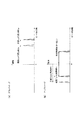
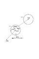
ダウンスイープで目標がX軸一定で、Y軸に沿って近づく場合は、ビート周波数空間では、近距離広角において、図6(a)に示すように、距離によるビート周波数成分frと速度によるビート周波数成分fdが加算され、外側に膨らむような航跡となる。この原理を、アップスイープの場合と合わせて、図7に示す。 When the target is constant along the X axis in the down sweep and approaches along the Y axis, in the beat frequency space, the beat frequency component fr according to the distance and the beat frequency due to the speed as shown in FIG. The component fd is added, resulting in a wake that swells outward. This principle is shown in FIG. 7 together with the case of up sweep.
ダウンスイープの場合は、距離によるビート周波数fbrと近づく速度によるビート周波数fbvは同一の正の周波数となる。一方、アップスイープの場合には、距離によるビート周波数fbrは負の周波数となり、近づく速度によるビート周波数fbvは正の方向の周波数となる。これを正の周波数として観測すると、折り返した周波数となり、ダウンスイープの場合とアップスイープの場合では、図8に示すような関係となる。これを(8)および(9)式により、X−Y軸に換算すると、上述した誤差が残留し、図8(b)に示すように、実際の車両の軌跡が直線の場合であっても、若干ずれた位置に観測される。 In the case of the down sweep, the beat frequency fbv by the speed approaching the beat frequency fbr by the distance is the same positive frequency. On the other hand, in the case of up sweep, the beat frequency fbr depending on the distance is a negative frequency, and the beat frequency fbv depending on the approaching speed is a frequency in the positive direction. When this is observed as a positive frequency, it becomes a folded frequency. In the case of the down sweep and the up sweep, the relationship is as shown in FIG. When this is converted into the XY axis by the equations (8) and (9), the above-mentioned error remains, and even if the actual vehicle trajectory is a straight line as shown in FIG. Observed at a slightly deviated position.
次に、この誤差を補正する手法を考える。ダウンスイープとアップスイープの場合の軌跡は、X−Y軸に変換すると、図8(b)に示すように、真値の軌跡に対して左右の逆方向に誤差が残留する。この逆方向へのズレを利用して、ダウンスイープとアップスイープの各々のX−Y軸に換算後の出力であるダウンスイープのXY換算値(xsd、ysd)とアップスイープのXY換算値(xsu,ysu)が所定のゲート範囲内にあれば、一般に、次式で結合することにより、位置精度を改善できる。
ここで、
(xs,ys) ;結合後のX−Y軸の位置
(xsd,ysd);ダウンスイープのX−Y軸換算後の位置
(xsu,ysu);アップスイープのX−Y軸換算後の位置
Wd ;ダウンスイープに対する重みづけ
Wu ;アップスイープに対する重みづけ=(1−Wd)
重みづけの例としては、ダウンスイープとアップスイープを均等にすればWd=Wu=0.5とすることができる。図8(b)に示すIFSAT補正値は、ダウンスイープのXY換算値とアップスイープのXY換算値とが重み付けされた値である。
here,
(Xs, ys); position of XY axis after combination (xsd, ysd); position after conversion of XY axis of down sweep (xsu, ysu); position after conversion of XY axis of up sweep Wd ; Weight for down sweep Wu; Weight for up sweep = (1-Wd)
As an example of weighting, Wd = Wu = 0.5 can be obtained by equalizing the down sweep and the up sweep. The IFSAT correction value shown in FIG. 8B is a value obtained by weighting the XY conversion value of the down sweep and the XY conversion value of the up sweep.
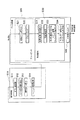
図9は、上述した誤差の補正を実現するための第2の実施形態に係るレーダ装置の構成を示す系統図である。このレーダ装置は、図1に示した第1の実施形態に係るレーダ装置の信号処理部30にダウンアップ結合部39が追加されて構成されている。
FIG. 9 is a system diagram showing a configuration of a radar apparatus according to the second embodiment for realizing the above-described error correction. This radar apparatus is configured by adding a down-up
ダウンアップ結合部39は、X−Y軸変換部38から送られてきたダウンスイープに基づく平滑値とアップスイープに基づく平滑値を結合し、外部に送る。
The down-up
次に、第2の実施形態に係るレーダ装置の動作を、図10に示すフローチャートを参照しながら説明する。最初に、信号処理が行われる(ステップS15)。この信号処理は、第1の実施形態のステップS10(図2参照)の処理が、ダウンスイープとアップスイープの信号を交互に送受信するダウン/アップ信号処理(ステップS16)に変更されている点を除けば、第1の実施形態のそれと同じである。 Next, the operation of the radar apparatus according to the second embodiment will be described with reference to the flowchart shown in FIG. First, signal processing is performed (step S15). In this signal processing, the processing in step S10 (see FIG. 2) of the first embodiment is changed to down / up signal processing (step S16) in which down sweep and up sweep signals are alternately transmitted and received. Except for this, it is the same as that of the first embodiment.
次いで、グルーピング処理が行われる(ステップS20)。このグルーピング処理は、第1の実施形態のそれと同様にオプションであり、複数ビームを形成する場合に実行される。 Next, a grouping process is performed (step S20). This grouping process is optional as in the first embodiment, and is executed when a plurality of beams are formed.
次いで、相関追尾処理が行われる(ステップS30)。この相関追尾処理は、ダウンスイープとアップスイープに対する処理が交互に行われる点を除けば、上述した第1の実施形態のそれと同じである。次いで、ダウン・アップ平滑値結合が行われる(ステップS50)、すなわち、ダウンアップ結合部39は、X−Y軸変換部38から送られてきたダウンスイープに基づく平滑値とアップスイープに基づく平滑値を結合する。
Next, correlation tracking processing is performed (step S30). This correlation tracking process is the same as that of the first embodiment described above except that the processes for down sweep and up sweep are performed alternately. Next, the down-up smoothing value combination is performed (step S50), that is, the down-up combining
次いで、平滑値のフィルタ処理が行われる(ステップS40)。これにより、平滑位置および平滑速度が出力される。その後、信号処理S10のステップS16に戻り、上述した処理が繰り返される。 Next, smoothing filter processing is performed (step S40). Thereby, a smooth position and a smooth speed are output. Then, it returns to step S16 of signal processing S10, and the process mentioned above is repeated.
なお、ゲートとしては、位置ゲートの他に、速度ゲートを用いて、ダウンスイープとアップスイープの速度である(vxd、vyd)と(vxu,vyu)が所定の範囲内にあるという条件を追加するように構成できる。 As the gate, in addition to the position gate, a speed gate is used to add a condition that (vxd, byd) and (vxu, vyu), which are down sweep and up sweep speeds, are within a predetermined range. It can be configured as follows.
以上説明したように、第2の実施形態に係るレーダ装置によれば、ダウンスイープとアップスイープの各々について第1の実施形態に係るレーダ装置により得られた結果を用いて、X−Y軸上で相関をとり、重みづけ平均化するので、位置および速度の精度を向上できる。 As described above, according to the radar apparatus according to the second embodiment, the results obtained by the radar apparatus according to the first embodiment for each of the down sweep and the up sweep are used on the XY axis. Since the correlation is taken and weighted and averaged, the accuracy of position and velocity can be improved.
(第3の実施形態)
第3の実施形態に係るレーダ装置において採用されている方式をAFSAT(Advanced FSAT)と呼ぶ。上述した第2の実施形態に係るレーダ装置では、ダウンスイープとアップスイープの位置の結合を用いるので、誤差を補正した位置を算出できる。
(Third embodiment)
A method adopted in the radar apparatus according to the third embodiment is called AFSAT (Advanced FSAT). Since the radar apparatus according to the second embodiment described above uses a combination of down sweep and up sweep positions, a position with corrected error can be calculated.
第3の実施形態に係るレーダ装置は、更に精度の高い位置を算出するようにしたものである。従来のレーダ装置においては、誤ペアリングにより、ゴーストが発生するという問題が存在するが、ペアリングが正しければ、より精度の高い位置を算出できる。ここでは、簡単のためダウンスイープとアップスイープによるペアリングを用いた測距測速方式をMPAT(Measured Pairing data Association and Tracking)と呼ぶ。 The radar apparatus according to the third embodiment calculates a position with higher accuracy. In the conventional radar apparatus, there is a problem that a ghost is generated due to erroneous pairing. However, if the pairing is correct, a position with higher accuracy can be calculated. Here, for the sake of simplicity, a distance measuring method using pairing by down sweep and up sweep is referred to as MPAT (Measured Pairing Data Association and Tracking).
図11は、MPAT方式を用いたレーダ装置の構成を示すブロック図である。このレーダ装置は、図9に示した第2の実施形態に係るレーダ装置の信号処理部30にペアリング処理部40および相関追尾部41が追加されて構成されている。
FIG. 11 is a block diagram showing a configuration of a radar apparatus using the MPAT method. This radar apparatus is configured by adding a
ペアリング処理部40は、測角部35からダウンスイープとアップスイープの各々に対する測角値を取得し、両者の測角値が所定の範囲にあるものをペアリングし、(19)式を用いて、距離および速度を算出する。このペアリング処理部40で算出された距離および速度は、相関追尾部41に送られる。
ここで、
B ;周波数帯域
R ;目標距離
T ;スイープ時間
c ;光速
V ;目標速度
λ ;波長
Δf1;ダウンチャープ信号の観測周波数
Δf2;アップチャープ信号の観測周波数
fd ;ドップラー周波数
fr ;距離による周波数
相関追尾部41は、ペアリング処理部40から送られてくる距離および速度により相関追尾を実施し、距離および速度の平滑値を算出してダウンアップ結合部39に送る。この平滑値の中には、図13に示すように、誤ペアリングによるゴーストであるMPATゴーストmも含まれているので、これを排除するために、第2の実施形態で算出した位置X−Y(IFSAT)aを中心に相関ゲートcgを形成し、ペアリングにより算出したX−Y(MPAT)mが相関ゲート内にある場合は、X−Y(IFSAT)aの結果を置き換える。また、置き換える際にX−Yの位置の差により段差が生じることを防ぐために、次式に示すようにIFSATとMPATのX−Yの値に重みづけする。
B; frequency band R; target distance T; sweep time c; speed of light V; target speed λ; wavelength Δf1; observation frequency of down-chirp signal Δf2; observation frequency of up-chirp signal fd; Doppler frequency fr; 41 performs correlation tracking based on the distance and speed sent from the
ここで、
(xs,ys) ;結合後のX−Y軸の位置
(xsa,ysa) ;IFSATのX−Y軸の位置
(xsm,ysm) ;MPATのX−Y軸の位置
Wa ;IFSATに対する重みづけ
Wm ;MPATに対する重みづけ=(1−Wa)
重みづけの例としては、IFSATとMPATを均等にすればWa=Wm=0.5とすればよい。
here,
(Xs, ys); position of XY axis after combination (xsa, ysa); position of XY axis of IFSAT (xsm, ysm); position of XY axis of MPAT Wa; weighting to IFSAT Wm ; Weighting for MPAT = (1-Wa)
As an example of weighting, if IFSAT and MPAT are made equal, Wa = Wm = 0.5 may be set.
なお、IFSATとMPATの相関をとる際には、両者の速度が所定の範囲内になるという条件を追加するように構成できる。 It should be noted that, when the correlation between IFSAT and MPAT is taken, a condition that both speeds are within a predetermined range can be added.
次に、第3の実施形態に係るレーダ装置の動作を、図12に示すフローチャートを参照しながら説明する。 Next, the operation of the radar apparatus according to the third embodiment will be described with reference to the flowchart shown in FIG.
最初に、信号処理が行われる(ステップS17)。この信号処理は、ステップS17の処理に、角度ゲート処理(ステップS18)および第1ペアリング処理(ステップS19)が追加されている点を除けば、第2の実施形態のステップS15(図10参照)で行われる信号処理と同じである。この信号処理では、まず、上述した第2の実施形態と同様に、ステップS16→ステップS12→ステップS13→ステップS14の処理が行われる。 First, signal processing is performed (step S17). This signal processing is performed in step S15 (see FIG. 10) of the second embodiment, except that angle gate processing (step S18) and first pairing processing (step S19) are added to the processing in step S17. ) Is the same as the signal processing performed in (1). In this signal processing, first, similarly to the above-described second embodiment, processing of step S16 → step S12 → step S13 → step S14 is performed.
次いで、グルーピング処理が行われる(ステップS20)。このグルーピング処理は、第1の実施形態のそれと同様にオプションであり、複数ビームを形成する場合に実行される。次いで、相関追尾処理が行われる(ステップS30)。この相関追尾処理は、上述した第2の実施形態のそれと同じである。 Next, a grouping process is performed (step S20). This grouping process is optional as in the first embodiment, and is executed when a plurality of beams are formed. Next, correlation tracking processing is performed (step S30). This correlation tracking process is the same as that of the second embodiment described above.
次いで、ダウン・アップ平滑値結合(近距離)が行われる(ステップS50)、すなわち、ダウンアップ結合部39は、X−Y軸変換部38から送られてきたダウンスイープに基づく平滑値とアップスイープに基づく平滑値を結合する。
Next, down / up smoothing value combination (short distance) is performed (step S50), that is, the down-up
上記ステップS17、S20、S30およびS40の処理と並行して、以下の処理が行われる。すなわち、信号処理では、ステップS14の処理が終了すると、角度ゲート処理が行われる(ステップS18)。すなわち、ペアリング処理部40は、相関ゲートを形成する。次いで、第1ペアリング処理が行われる(ステップS19)。すなわち、ペアリング処理部40は、測角部35からダウンスイープとアップスイープの各々に対する測角値を取得し、両者の測角値が所定の範囲にあるものをペアリングして距離および速度を算出し、相関追尾部41に送る。
In parallel with the processes in steps S17, S20, S30, and S40, the following processes are performed. That is, in the signal processing, when the processing in step S14 is completed, angle gate processing is performed (step S18). That is, the
次いで、グルーピング処理が行われる(ステップS20a)。このグルーピング処理は、第1の実施形態のそれと同様にオプションであり、複数ビームを形成する場合に実行される。次いで、相関追尾処理が行われる(ステップS30a)。この相関追尾処理は、上述したステップS30の処理からステップS34の処理、つまりfbx、fbyの平滑値よりX、Y、Vx、Vy、AxおよびAyを算出する処理を除去したものである。 Next, a grouping process is performed (step S20a). This grouping process is optional as in the first embodiment, and is executed when a plurality of beams are formed. Next, correlation tracking processing is performed (step S30a). This correlation tracking process is obtained by removing the process of step S30 from the process of step S34 described above, that is, the process of calculating X, Y, Vx, Vy, Ax, and Ay from the smooth values of fbx and fby.
次いで、相関があれば置き換える処理が行われる(ステップS60)。すなわち、相関追尾部41は、ペアリングにより算出したX−Y(MPAT)mが相関ゲートcg内にある場合は、X−Y(IFSAT)iの結果を置き換える。
Next, if there is a correlation, a replacement process is performed (step S60). That is, the
次いで、平滑値結合が行われる(ステップS70)。すなわち、ダウンアップ結合部39は、X−Y軸変換部38から送られてきたダウンスイープに基づく平滑値とアップスイープに基づく平滑値を結合した結果に、更に、相関追尾部41から送られてきた平滑値を結合する。
Next, smooth value combination is performed (step S70). That is, the down-up
次いで、平滑値のフィルタが行われる(ステップS40)。その後、ステップS16に戻り、上述した処理が繰り返される。 Next, a smooth value filter is performed (step S40). Then, it returns to step S16 and the process mentioned above is repeated.
以上説明したように、第3の実施形態に係るレーダ装置によれば、第2の実施形態に係るレーダ装置により得られた結果と、ダウンスイープとアップスイープによるペアリング結果の観測値を用いた相関追尾の結果との相関をとるので、ダウンスイープーアップスイープの誤ペアリングによるゴーストを抑えつつ、位置および速度の精度を向上できる。 As described above, according to the radar apparatus according to the third embodiment, the result obtained by the radar apparatus according to the second embodiment and the observed value of the pairing result by the down sweep and the up sweep are used. Since the correlation with the result of the correlation tracking is obtained, the accuracy of the position and speed can be improved while suppressing the ghost due to the erroneous pairing of the down sweep up sweep.
なお、上述した第3の実施形態に係るレーダ装置は、第2の実施形態に係るレーダ装置にペアリングを適用して精度向上を図るようにしたものであるが、第1の実施形態に係るレーダ装置にペアリングを適用して精度向上を図るように構成することもできる。 Note that the radar apparatus according to the third embodiment described above is designed to improve accuracy by applying pairing to the radar apparatus according to the second embodiment, but according to the first embodiment. The radar apparatus can also be configured to improve accuracy by applying pairing.
本発明のいくつかの実施形態を説明したが、これらの実施形態は、例として提示したものであり、発明の範囲を限定することは意図していない。これら新規な実施形態は、その他の様々な形態で実施されることが可能であり、発明の要旨を逸脱しない範囲で、種々の省略、置き換え、変更を行うことができる。これら実施形態やその変形は、発明の範囲や要旨に含まれるとともに、特許請求の範囲に記載された発明とその均等の範囲に含まれる。 Although several embodiments of the present invention have been described, these embodiments are presented by way of example and are not intended to limit the scope of the invention. These novel embodiments can be implemented in various other forms, and various omissions, replacements, and changes can be made without departing from the scope of the invention. These embodiments and modifications thereof are included in the scope and gist of the invention, and are included in the invention described in the claims and the equivalents thereof.
10 アンテナ
11 アンテナ送信素子
12 複数のアンテナ受信素子
20 送受信器
21 送信器
22 複数のミキサ
30 信号処理器
31 AD変換器
32 FFT部
33 DBF部
34 検出部
35 測角部
36 ビート周波数軸変換部
37 相関追尾部
38 X−Y軸変換部
39 ダウンアップ結合部
40 ペアリング処理部
41 相関追尾部
DESCRIPTION OF
Claims (4)
前記送受信器からの信号に基づく測角値を用いてビート周波数の空間を表すfbx−fby軸に座標変換するビート周波数軸変換部と、
前記ビート周波数軸変換部における変換によって得られたfbx−fby軸の空間において位置、速度および加速度を用いて相関追尾を行う相関追尾部と、
前記相関追尾部における相関追尾によって得られた結果をX−Y軸の位置および速度に変換するX−Y軸変換部と、
を備えることを特徴とするレーダ装置。 A transceiver that repeatedly transmits and receives a FMCW down sweep or up sweep signal;
A beat frequency axis conversion unit that converts coordinates to an fbx-fby axis that represents a beat frequency space using an angle measurement value based on a signal from the transceiver;
A correlation tracking unit that performs correlation tracking using position, velocity, and acceleration in the space of the fbx-fby axis obtained by the conversion in the beat frequency axis conversion unit;
An XY axis conversion unit that converts a result obtained by correlation tracking in the correlation tracking unit into an XY axis position and velocity;
A radar apparatus comprising:
前記送受信器からのダウンスイープおよびアップスイープの信号の各々において、該信号に基づく測角値を用いてビート周波数の空間を表すfbx−fby軸に座標変換するビート周波数軸変換部と、
前記ビート周波数軸変換部における変換によって得られたfbx−fby軸の空間において位置、速度および加速度を用いて相関追尾を行う相関追尾部と、
前記相関追尾部における相関追尾によって得られた結果をX−Y軸の位置および速度に変換するX−Y軸変換部と、
前記X−Y軸変換部で得られたダウンスイープとアップスイープの位置または速度の少なくとも一方の差が所定値以下であれば、該位置、速度または加速度を重みづけして結合した値を求めるダウンアップ結合部と、
を備えることを特徴とするレーダ装置。 A transceiver that repeatedly transmits and receives FMCW down-sweep and up-sweep signals;
In each of the down sweep and up sweep signals from the transmitter / receiver, a beat frequency axis conversion unit that performs coordinate conversion to an fbx-fby axis that represents a beat frequency space using an angle measurement value based on the signal;
A correlation tracking unit that performs correlation tracking using position, velocity, and acceleration in the space of the fbx-fby axis obtained by the conversion in the beat frequency axis conversion unit;
An XY axis conversion unit that converts a result obtained by correlation tracking in the correlation tracking unit into an XY axis position and velocity;
If the difference between at least one of the down sweep and the up sweep position or speed obtained by the X-Y axis converter is equal to or smaller than a predetermined value, the down is obtained by weighting and combining the position, speed or acceleration. An up coupling,
A radar apparatus comprising:
前記ペアリング処理部におけるペアリングにより得られた距離および速度により相関追尾を実施して距離および速度の平滑値を算出する他の相関追尾部を備え、
前記ダウンアップ結合部は、前記他の相関追尾部により得られた平滑値と、前記相関追尾部により得られた平滑値の位置および速度の少なくとも1つの差が所定値以下であれば、該位置、速度または加速度を重みづけして結合した値を求めることを特徴とする請求項2記載のレーダ装置。 A pairing processing unit for pairing those whose angle measurement values for each of the down sweep and the up sweep are within a predetermined range;
Another correlation tracking unit that calculates a smooth value of the distance and speed by performing correlation tracking by the distance and speed obtained by pairing in the pairing processing unit,
If the difference between the smooth value obtained by the other correlation tracking unit and the position and speed of the smooth value obtained by the correlation tracking unit is equal to or smaller than a predetermined value, the down-up coupling unit 3. The radar apparatus according to claim 2, wherein a value obtained by combining the speed or acceleration is obtained.
前記ペアリング処理部におけるペアリングにより得られた距離および速度により相関追尾を実施して距離および速度の平滑値を算出する他の相関追尾部と、
前記他の相関追尾部により得られた平滑値と、前記相関追尾部により得られた平滑値の位置および速度の少なくとも1つの差が所定値以下であれば、該位置、速度または加速度を重みづけして結合した値を求めるダウンアップ結合部とを備えることを特徴とする請求項1記載のレーダ装置。 A pairing processing unit for pairing an angle measurement value for a down sweep or an up sweep within a predetermined range;
Another correlation tracking unit that performs correlation tracking based on the distance and speed obtained by pairing in the pairing processing unit and calculates a smooth value of the distance and speed;
If the difference between at least one of the smoothed value obtained by the other correlation tracking unit and the smoothed value obtained by the correlation tracking unit is less than or equal to a predetermined value, the position, velocity or acceleration is weighted. The radar apparatus according to claim 1, further comprising a down-up combination unit that obtains a combined value.
Priority Applications (2)
| Application Number | Priority Date | Filing Date | Title |
|---|---|---|---|
| JP2010138277A JP5491981B2 (en) | 2010-06-17 | 2010-06-17 | Radar equipment |
| PCT/JP2011/063524 WO2011158800A1 (en) | 2010-06-17 | 2011-06-13 | Radar device |
Applications Claiming Priority (1)
| Application Number | Priority Date | Filing Date | Title |
|---|---|---|---|
| JP2010138277A JP5491981B2 (en) | 2010-06-17 | 2010-06-17 | Radar equipment |
Publications (2)
| Publication Number | Publication Date |
|---|---|
| JP2012002686A JP2012002686A (en) | 2012-01-05 |
| JP5491981B2 true JP5491981B2 (en) | 2014-05-14 |
Family
ID=45348199
Family Applications (1)
| Application Number | Title | Priority Date | Filing Date |
|---|---|---|---|
| JP2010138277A Active JP5491981B2 (en) | 2010-06-17 | 2010-06-17 | Radar equipment |
Country Status (2)
| Country | Link |
|---|---|
| JP (1) | JP5491981B2 (en) |
| WO (1) | WO2011158800A1 (en) |
Families Citing this family (2)
| Publication number | Priority date | Publication date | Assignee | Title |
|---|---|---|---|---|
| JP6313981B2 (en) * | 2014-01-22 | 2018-04-18 | 株式会社デンソーテン | Radar apparatus, vehicle control system, and signal processing method |
| CN109782267B (en) * | 2019-01-25 | 2021-01-22 | 北京润科通用技术有限公司 | Track correlation method and vehicle-mounted radar |
Family Cites Families (4)
| Publication number | Priority date | Publication date | Assignee | Title |
|---|---|---|---|---|
| JP4038420B2 (en) * | 2002-10-28 | 2008-01-23 | 三菱電機株式会社 | Radar data processing apparatus and distance / speed measuring method |
| JP4186744B2 (en) * | 2003-08-01 | 2008-11-26 | 三菱電機株式会社 | Radar equipment |
| US7791530B2 (en) * | 2006-01-05 | 2010-09-07 | Autoliv Asp, Inc. | Time duplex apparatus and method for radar sensor front-ends |
| JP2010002389A (en) * | 2008-06-23 | 2010-01-07 | Fujitsu Ten Ltd | Signal processing device, radar device, and signal processing method |
-
2010
- 2010-06-17 JP JP2010138277A patent/JP5491981B2/en active Active
-
2011
- 2011-06-13 WO PCT/JP2011/063524 patent/WO2011158800A1/en active Application Filing
Also Published As
| Publication number | Publication date |
|---|---|
| WO2011158800A1 (en) | 2011-12-22 |
| JP2012002686A (en) | 2012-01-05 |
Similar Documents
| Publication | Publication Date | Title |
|---|---|---|
| CN107064861B (en) | Apparatus for estimating angle of arrival and apparatus for beamforming | |
| JP5468304B2 (en) | Radar equipment | |
| CN108885254B (en) | Object detection device | |
| JP5407272B2 (en) | Radar equipment | |
| JP6818541B2 (en) | Radar device and positioning method | |
| JP2020509386A (en) | Method and apparatus for capturing surroundings | |
| KR101360572B1 (en) | Method for multi target detecting fmcw radar and apparatus thereof | |
| WO2013080570A1 (en) | Radar device | |
| WO2013088938A1 (en) | Radar device | |
| JP2016151425A (en) | Radar system | |
| JP5578866B2 (en) | Radar equipment | |
| JPWO2008053685A1 (en) | Radar target detection method and radar apparatus using the target detection method | |
| JP2014182010A (en) | Radar apparatus | |
| JP2018059895A (en) | Multi-radar system | |
| JP6324327B2 (en) | Passive radar equipment | |
| JP5554384B2 (en) | FMCW radar apparatus and signal processing method for FMCW radar | |
| JP2017106799A (en) | Synthetic-aperture radar device and radar signal processing method thereof | |
| JP5491981B2 (en) | Radar equipment | |
| JP6546109B2 (en) | Radar equipment | |
| RU2660450C1 (en) | Device of radar location station with continuous linear-frequency-modulated signal and synthesis of aperture | |
| JP5508877B2 (en) | Radar equipment | |
| JP5677275B2 (en) | Radar device and vehicle | |
| JP6573748B2 (en) | Radar equipment | |
| JP5163765B2 (en) | Angle measuring device, radar device, angle measuring method and angle measuring program | |
| JP2015052549A (en) | Synthetic aperture radar system and method of image processing thereof |
Legal Events
| Date | Code | Title | Description |
|---|---|---|---|
| A621 | Written request for application examination |
Free format text: JAPANESE INTERMEDIATE CODE: A621 Effective date: 20130128 |
|
| TRDD | Decision of grant or rejection written | ||
| A01 | Written decision to grant a patent or to grant a registration (utility model) |
Free format text: JAPANESE INTERMEDIATE CODE: A01 Effective date: 20140204 |
|
| A61 | First payment of annual fees (during grant procedure) |
Free format text: JAPANESE INTERMEDIATE CODE: A61 Effective date: 20140228 |
|
| R151 | Written notification of patent or utility model registration |
Ref document number: 5491981 Country of ref document: JP Free format text: JAPANESE INTERMEDIATE CODE: R151 |